EP1628089A2 - Device for cooling of a cryostat arrangement - Google Patents
Device for cooling of a cryostat arrangement Download PDFInfo
- Publication number
- EP1628089A2 EP1628089A2 EP05016144A EP05016144A EP1628089A2 EP 1628089 A2 EP1628089 A2 EP 1628089A2 EP 05016144 A EP05016144 A EP 05016144A EP 05016144 A EP05016144 A EP 05016144A EP 1628089 A2 EP1628089 A2 EP 1628089A2
- Authority
- EP
- European Patent Office
- Prior art keywords
- cooling device
- heat
- cryostat
- cold
- cryocooler
- Prior art date
- Legal status (The legal status is an assumption and is not a legal conclusion. Google has not performed a legal analysis and makes no representation as to the accuracy of the status listed.)
- Granted
Links
- 238000001816 cooling Methods 0.000 title claims abstract description 80
- IJGRMHOSHXDMSA-UHFFFAOYSA-N Atomic nitrogen Chemical compound N#N IJGRMHOSHXDMSA-UHFFFAOYSA-N 0.000 claims abstract description 40
- SWQJXJOGLNCZEY-UHFFFAOYSA-N helium atom Chemical compound [He] SWQJXJOGLNCZEY-UHFFFAOYSA-N 0.000 claims abstract description 30
- 239000001307 helium Substances 0.000 claims abstract description 29
- 229910052734 helium Inorganic materials 0.000 claims abstract description 29
- 230000005855 radiation Effects 0.000 claims abstract description 22
- 239000007789 gas Substances 0.000 claims abstract description 20
- 229910052757 nitrogen Inorganic materials 0.000 claims abstract description 20
- 239000007788 liquid Substances 0.000 claims description 56
- 239000000725 suspension Substances 0.000 claims description 32
- 238000005481 NMR spectroscopy Methods 0.000 claims description 16
- 238000012546 transfer Methods 0.000 claims description 8
- 238000007789 sealing Methods 0.000 claims description 5
- 230000008878 coupling Effects 0.000 claims description 4
- 238000010168 coupling process Methods 0.000 claims description 4
- 238000005859 coupling reaction Methods 0.000 claims description 4
- 238000009835 boiling Methods 0.000 claims description 3
- 238000002595 magnetic resonance imaging Methods 0.000 claims description 3
- 238000004611 spectroscopical analysis Methods 0.000 claims description 3
- 239000012530 fluid Substances 0.000 abstract 1
- 238000010992 reflux Methods 0.000 abstract 1
- 238000001704 evaporation Methods 0.000 description 4
- 230000002349 favourable effect Effects 0.000 description 3
- 238000009434 installation Methods 0.000 description 3
- 238000000034 method Methods 0.000 description 3
- 238000005253 cladding Methods 0.000 description 2
- 238000013461 design Methods 0.000 description 2
- 238000009413 insulation Methods 0.000 description 2
- 229910000765 intermetallic Inorganic materials 0.000 description 2
- 238000012423 maintenance Methods 0.000 description 2
- 239000000463 material Substances 0.000 description 2
- 239000002184 metal Substances 0.000 description 2
- 229910052751 metal Inorganic materials 0.000 description 2
- 230000006978 adaptation Effects 0.000 description 1
- 230000002238 attenuated effect Effects 0.000 description 1
- 150000001875 compounds Chemical class 0.000 description 1
- 238000010276 construction Methods 0.000 description 1
- 230000007423 decrease Effects 0.000 description 1
- 238000011161 development Methods 0.000 description 1
- 210000005069 ears Anatomy 0.000 description 1
- 230000000694 effects Effects 0.000 description 1
- 238000005516 engineering process Methods 0.000 description 1
- 230000008020 evaporation Effects 0.000 description 1
- 238000010438 heat treatment Methods 0.000 description 1
- 201000009240 nasopharyngitis Diseases 0.000 description 1
- 230000010355 oscillation Effects 0.000 description 1
- 230000000149 penetrating effect Effects 0.000 description 1
- 238000005057 refrigeration Methods 0.000 description 1
- 230000001105 regulatory effect Effects 0.000 description 1
Images


Classifications
-
- F—MECHANICAL ENGINEERING; LIGHTING; HEATING; WEAPONS; BLASTING
- F25—REFRIGERATION OR COOLING; COMBINED HEATING AND REFRIGERATION SYSTEMS; HEAT PUMP SYSTEMS; MANUFACTURE OR STORAGE OF ICE; LIQUEFACTION SOLIDIFICATION OF GASES
- F25D—REFRIGERATORS; COLD ROOMS; ICE-BOXES; COOLING OR FREEZING APPARATUS NOT OTHERWISE PROVIDED FOR
- F25D19/00—Arrangement or mounting of refrigeration units with respect to devices or objects to be refrigerated, e.g. infrared detectors
-
- F—MECHANICAL ENGINEERING; LIGHTING; HEATING; WEAPONS; BLASTING
- F25—REFRIGERATION OR COOLING; COMBINED HEATING AND REFRIGERATION SYSTEMS; HEAT PUMP SYSTEMS; MANUFACTURE OR STORAGE OF ICE; LIQUEFACTION SOLIDIFICATION OF GASES
- F25B—REFRIGERATION MACHINES, PLANTS OR SYSTEMS; COMBINED HEATING AND REFRIGERATION SYSTEMS; HEAT PUMP SYSTEMS
- F25B9/00—Compression machines, plants or systems, in which the refrigerant is air or other gas of low boiling point
- F25B9/14—Compression machines, plants or systems, in which the refrigerant is air or other gas of low boiling point characterised by the cycle used, e.g. Stirling cycle
- F25B9/145—Compression machines, plants or systems, in which the refrigerant is air or other gas of low boiling point characterised by the cycle used, e.g. Stirling cycle pulse-tube cycle
-
- F—MECHANICAL ENGINEERING; LIGHTING; HEATING; WEAPONS; BLASTING
- F25—REFRIGERATION OR COOLING; COMBINED HEATING AND REFRIGERATION SYSTEMS; HEAT PUMP SYSTEMS; MANUFACTURE OR STORAGE OF ICE; LIQUEFACTION SOLIDIFICATION OF GASES
- F25B—REFRIGERATION MACHINES, PLANTS OR SYSTEMS; COMBINED HEATING AND REFRIGERATION SYSTEMS; HEAT PUMP SYSTEMS
- F25B2309/00—Gas cycle refrigeration machines
- F25B2309/14—Compression machines, plants or systems characterised by the cycle used
- F25B2309/1408—Pulse-tube cycles with pulse tube having U-turn or L-turn type geometrical arrangements
-
- F—MECHANICAL ENGINEERING; LIGHTING; HEATING; WEAPONS; BLASTING
- F25—REFRIGERATION OR COOLING; COMBINED HEATING AND REFRIGERATION SYSTEMS; HEAT PUMP SYSTEMS; MANUFACTURE OR STORAGE OF ICE; LIQUEFACTION SOLIDIFICATION OF GASES
- F25B—REFRIGERATION MACHINES, PLANTS OR SYSTEMS; COMBINED HEATING AND REFRIGERATION SYSTEMS; HEAT PUMP SYSTEMS
- F25B2400/00—General features or devices for refrigeration machines, plants or systems, combined heating and refrigeration systems or heat-pump systems, i.e. not limited to a particular subgroup of F25B
- F25B2400/17—Re-condensers
-
- F—MECHANICAL ENGINEERING; LIGHTING; HEATING; WEAPONS; BLASTING
- F25—REFRIGERATION OR COOLING; COMBINED HEATING AND REFRIGERATION SYSTEMS; HEAT PUMP SYSTEMS; MANUFACTURE OR STORAGE OF ICE; LIQUEFACTION SOLIDIFICATION OF GASES
- F25B—REFRIGERATION MACHINES, PLANTS OR SYSTEMS; COMBINED HEATING AND REFRIGERATION SYSTEMS; HEAT PUMP SYSTEMS
- F25B9/00—Compression machines, plants or systems, in which the refrigerant is air or other gas of low boiling point
- F25B9/10—Compression machines, plants or systems, in which the refrigerant is air or other gas of low boiling point with several cooling stages
Definitions
- the invention relates to a cooling device for the re-liquefaction of cryogenic gases, with an outer shell defining a vacuum space, and a built-in cold head of a cryocooler having at least two cold stages and which is at least partially surrounded by a radiation shield.
- the example two-stage cold head of the cryocooler is usually installed in a separate, vacuum-cladding tube (as described for example in US5613376) or directly into the vacuum space of a cryostat (as described for example in US5563566) so that the first cold stage of the cold head fixed with a radiation shield and the second cold stage is thermally conductively connected via a fixed thermal bridge or directly to the helium vessel where the superconductive magnet is in liquid helium.
- the cold head may be inserted into a neck tube connecting the outer vacuum envelope of the cryostat to the helium vessel and correspondingly filled with helium gas, as described, for example, in US2002 / 0002830A1.
- the first cold stage of the two-stage cold head is again solidly contacted with a radiation shield, the second cold stage hangs freely in the helium atmosphere and liquefies directly evaporated helium.
- cryocooler cooled device that can be used to re-liquefy a single vaporized cryogen.
- the magnet In a hitherto conventional cryostat arrangement for, for example, a superconducting magnet system, the magnet is usually installed in a container filled with liquid helium of 4.2 K. The He container is usually surrounded by an exhaust-cooled radiation shield and another, cooled with liquid nitrogen shield, so that the heat input is minimized to the helium container from the outside. Passive cooling by the evaporating cryogens causes liquid helium and nitrogen to be replenished at certain intervals.
- JP11257770 and JP2000283578 it is therefore proposed to introduce into the existing neck or suspension tubes of a nitrogen container of a cryostat assembly a heat transfer device in the form of a heat pipe which is connected to the cold head of a cryocooler and liquefies vaporized nitrogen (see also: Advances of Cryogenic Engineering , 45, 41-48).
- the condenser is flanged directly to the cold head of the single-stage pulse tube cooler. This consists of a thin tube in which the nitrogen vapor rises, is liquefied at a contacted with the cold head cold surface and then runs along the pipe wall down.
- the cold head of the cryocooler In both cases (nitrogen or helium liquefier), the cold head of the cryocooler is located in an outer jacket which limits a vacuum space.
- the cold head When using multi-stage cryocoolers, it is common that parts of the cold head are surrounded by a radiation shield, which is contacted with a (but not the coldest) cold stage, so that the cold head is well insulated against heat radiation in the low temperature range.
- cryostat arrangements such as those used in magnetic systems for high-resolution nuclear magnetic resonance (NMR)
- NMR nuclear magnetic resonance
- various conventional cryostat arrangements do not have just one cryogen: in addition to a container filled with liquid helium and containing the magnet, for example, there is also a liquid Nitrogen cooled radiation shield.
- this object is achieved in that at least two cold stages of the cold head of the cryocooler for each thermally conductively connected to a heat transmitting device, each in the neck or suspension tubes of a cryostat for storage of at least two different cryogenic Liquids can be introduced.
- Such a cooling device offers the following advantages: existing cryostat arrangements, and in particular those containing superconducting magnets, can be retrofitted without (or with only minor) adaptations so that cryogenic loss-free operation is possible even with the use of multiple cryogens with a low outlay on equipment becomes. No redesign of the cryostat is necessary. The additional heat input into the cryostat resulting from the device is modest and relatively predictable with suitable design.
- the heat transferring devices in which the liquefaction of the cryogens takes place are designed so that they can be introduced without contact into the neck or suspension tubes of the cryostat assembly.
- the evaporating gas is liquefied thermodynamically efficient, because the steam is not overheated and therefore does not have to be cooled down again to condensing temperature.
- the coldhead of the cryocooler is so far away from the magnetic center of a superconducting magnet assembly incorporated in the cryostat that disturbances from the magnetic regenerator material to the magnet assembly are much less noticeable than if the coldhead were integrated directly into the cryostat. Conversely, the function of the cryocooler is less affected by the magnetic field of the magnet assembly. If the cryocooler fails or has to be shut down for maintenance, the cryostat assembly, for example, when used to cool a superconducting magnet assembly, still serves its purpose ensures a high level of operational safety. In addition, the user can freely determine the mode of operation (conventional or cryogenic loss-free).
- At least one of the heat-transferring devices has a cavity, which is connected to an open line, in particular a pipeline.
- an open line in particular a pipeline.
- the cryogen vaporized from the liquid tank of the cryostat is led into the cavity at the cold stage, where it is liquefied.
- the condensate then flows back through the pipeline into the liquid tank of the cryostat.
- the heat transfer device in this form corresponds to the heat pipes known from heat technology.
- At least one of the heat-transferring devices has a metallic compound which conducts heat very well, liquefied at the end of which cryogen has evaporated from the liquid tank of the cryostat and then flows back again into the liquid bath of the liquid tank of the cryostat.
- This connection is flanged at the other end to a cold stage of the cold head of the cryocooler.
- Any combinations of the heat transferring devices are possible.
- a metallic connection which conducts the heat very well can be flanged, while the second cold stage is connected to a pipeline.
- cryocooler is a pulse tube cooler, since pulse tube coolers can be operated with particularly low vibration. Pulse tube coolers are also very reliable and low maintenance.
- the operation of the cooling device is also very well possible with a Gifford-McMahon cooler.
- a disadvantage of this cryocooler compared to a pulse tube cooler are the larger vibrations. This disadvantage does not apply if soft sealing elements are used between the cryocooler and the cryostat arrangement, as described below.
- At least one connecting line open on both sides is provided, via which the cold head of the cryocooler can be connected to at least one neck or suspension tube of the liquid tank with the cryogenic cryogen into which no heat transferring device is introduced is thermally contacted with at least two cold stages of the cold head and possibly also with a regenerator above the coldest cold stage, and wherein the conduit opens after thermal contact with the coldest cold stage in the cavity mounted on the cold head or is guided along the metallic compound in the liquid tank.
- the gas in the line is cooled at the cold head of the cryocooler and liquefied at the coldest cold stage, so that due to the resulting suction, a flow in the line through the neck or suspension tubes to the cooling device is formed.
- the gas flow causes the neck or suspension tubes to be cooled by the gas being heated, thereby ideally completely compensating for the heat input via the neck or suspension tubes.
- a valve and / or a pump for regulating the gas flow is provided in the connecting line between the neck or suspension tubes and the cold head.
- helium can be liquefied at a temperature of 4.2 K or at a lower temperature at the coldest cold stage of the cold head, since this offers a multitude of possible uses in the lowest temperature range.
- the helium loss and the refilling operations can be reduced or can be achieved at sufficiently large cooling capacity of the cryocooler lossless operation.
- Another advantageous aspect involves that at a cold stage of the cold head of the cryocooler liquid nitrogen at 77 K or at a lower temperature can be generated.
- a cold stage of the cold head which is not the coldest, is thermally conductively connected to the radiation shield at least partially surrounding the cold head. In this way, the heat input is substantially reduced by radiation to the colder components of the cold head.
- the heat-transferring device at least partially comes to rest within the outer jacket of the cooling device, ie within the vacuum space. This is particularly relevant to the part of the heat transfer device which is connected to the cold head of the cryocooler. Thus, this part of the heat transfer device is very well insulated against heat conduction to the outside.
- the heat-transmitting device is at least partially surrounded by a first tube in the area outside the outer jacket.
- This tube serves to heat-isolate the heat-transferring device. It may or may not have the same diameter along its entire length. For example, it may be cheaper by design to choose the smallest possible part for one part of the pipe and a larger one for the rest.
- the first tube surrounding the heat-transferring device is open at one end and connected there to the vacuum space of the outer jacket, while at the other end it is gas-tightly connected to the pipeline or the metallic connection of the heat-transferring device. If the vacuum space of the cooling device is evacuated in this embodiment, the part of the heat-transmitting device surrounded by the first pipe is also under vacuum. The heat transferring device is then very well insulated in this area to the outside against heat conduction.
- the first tube surrounding the heat-transferring device is connected in a gastight manner at both ends to the pipeline or the metallic connection of the heat-transferring device and provided with a separate connection for evacuation.
- the interior of the tube can thereby be evacuated and the part of the heat-transferring device surrounded by the tube can be isolated very well to the outside against heat conduction.
- the pipeline or the metallic connection of the heat-transferring device is at least partially surrounded by a further, second tube, which is thermally conductively connected to the radiation shield.
- This tube is arranged within the first tube, which - as just described - the vacuum insulation is used. In this way, the part of the heat transferring device surrounded by the second tube is insulated very well from heat radiation.
- the heat-transferring device is at least partially flexible, in particular as a bellows or in the form of interwoven wires to wires, is executed.
- an embodiment of the cooling device according to the invention can be realized, in which the heat-transferring device is flexible together with the surrounding tubes, which can facilitate their installation in the neck or suspension tubes of a Kryostatan angel substantially.
- the heat-transferring device and the surrounding pipes connect to each other at least one location by means of a gas-tight coupling and separate from each other to let.
- the coupling is constructed so that the functionality of the heat transmitting device is not affected, including the surrounding pipes.
- the attachment of the cooling device is made much easier on a Kryostatanaku.
- the cooling device can be attached gas-tight to the cryostat for the storage of cryogenic liquids. This can be done either on the neck or suspension tubes or on the outer shell of the Kryostatan extract.
- the cooling device may be external to the cryostat, e.g. on the ceiling or on a separate stand, be attached.
- the weight of the cooling device then does not load on the cryostat arrangement. This may increase the mechanical stability of the cryostat assembly.
- cryocooler electric heaters Furthermore, it is possible to attach to the cold stages of the cold head of the cryocooler electric heaters. With an excess power, the heaters can be adjusted so that the cryocooler precisely compensates for the incidence of heat on the various containers of the Kryostatan nie.
- the cooling device is used for cooling a superconducting magnet arrangement, in particular if the superconducting magnet arrangement is part of an apparatus for nuclear magnetic resonance, in particular magnetic resonance imaging (MRI) or magnetic resonance spectroscopy (NMR).
- MRI magnetic resonance imaging
- NMR magnetic resonance spectroscopy
- an electrical heater to be introduced into the liquid tank via a neck or suspension tube of at least one liquid tank in a cryostat arrangement provided with the cooling device according to the invention.
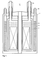
- Fig. 1 shows a schematic representation of a cryostat 1 with a magnet assembly 5 , as is customary for MR applications used.
- the cryostat 1 comprises a helium-filled liquid tank 2a which is connected to suspension tubes 3a, with an outer casing 4 of the cryostat 1, and in which a magnet assembly 5 is arranged.
- a further liquid tank 2 b is arranged around the liquid tank 2 a, which contains nitrogen and is connected to the suspension tubes 3 b with the outer jacket 4 of the cryostat 1.
- the liquid tank 2b with nitrogen is thermally contacted with the hanger ears 3a.
- an exhaust-cooled radiation shield 6 is arranged, which in turn is thermally contacted with the suspension tubes 3a.
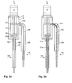
- FIG. 2 a shows an embodiment of a cooling device 7 according to the invention.
- the cooling device comprises an outer jacket 8 , which delimits a vacuum space 9 , and a cold head 10 of a cryocooler, which has at least two cold stages 11, 12 and which is at least partially surrounded by a radiation shield 13 .
- the cold stages 11, 12 of the cold head 10 are each thermally conductively connected to a heat transfer device 14a, 14b .
- the heat-transferring devices 14a, 14b each have a cavity 15a, 15b , wherein the cavities 15a, 15b are each connected to a pipeline 16a, 16b .
- FIG. 2b shows an alternative embodiment of the cooling device 7 according to the invention, in which the heat-transferring devices 14a, 14b have connections 17a, 17b which can conduct heat very well.
- These compounds may, for example, be in the form of cold fingers, which are generally in the form of metal rods.
- Such a metal bar should have the greatest possible Have cross-sectional area, so that the temperature difference across the rod remains as small as possible.
- the piping 16a, 16b may be introduced into the hanger pipes 3a, 3b from the liquid tanks 2a, 2b of a cryostat 1.
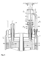
- Fig. 3 shows a cooling device 7 according to the invention in the installed state.
- the pipelines 16a, 16b are located here in the cryogenic vapor above the liquid surface of the cryogens 18a, 18b located in the liquid tanks 2a, 2b.
- the heat-transferring devices 14a, 14b are each thermally conductively connected to a cold stage 11, 12 of the cryocooler.
- cryogens 18a, 18b vaporized from the liquid tanks 2a, 2b of the cryostat 1 are passed through the conduits 16a, 16b into the cavity 15a, 15b at the respective refrigeration stage 12, 11 where the cryogens 18a, 18b condense and are thus liquefied then flow back into the liquid tanks 2a, 2b of the cryostat 1 through the pipes 16a, 16b.
- the helium vapor can also be liquefied at the end of a metallic, very good heat conductive connection 17a, 17b, which is contacted with the cold head 10, as shown in Fig. 2b.
- the cryogen 18b boiling at a higher temperature is liquefied from the liquid tank 2b at the first cold stage 11 of the cold head 10, while the liquefaction of the lower-boiling cryogen 18a takes place at the second, colder cold stage 12 of the cold head 10.
- the invention also includes cooling devices with a multi-stage cold head 10, so that in principle any number of cryogens, corresponding to the number of cold stages of the cold head 10, can be liquefied.
- first tube 19a, 19b which is connected to the vacuum space 9 of the outer jacket 8 of the cooling device 7 and can be evacuated together with the vacuum space 9 (see FIG , 2 B).
- a second tube 20 is arranged inside the first tube 19a and is thermally conductively connected to the radiation shield 13.
- the diameter of the first Pipe 19b is not the same in Fig. 2a, 2b and Fig. 3 over the entire length. It may be necessary for the tube at the closed end to be reduced to a smaller diameter so that it can be inserted without contact into the suspension tube 3b of the liquid tank 2b.
- this is designed as a bellows.
- a bellows can also be inserted in each case between the first tube 19a and the outer jacket 8 and in a section of the second tube 20.
- Flexible connectors 21a, 21b (such as wire strands braided into strands) can be used to make the metallic connection 17a, 17b shown in Fig. 2b movable. With an excess power of the cryocooler, additional heaters (not shown) may be attached to the cold stages 11, 12 of the cold head 10 of the cryocooler.
- the pressure in the liquid tanks 2a, 2b for the cryogens 18a, 18b with heaters 22a, 22b in the liquid tanks 2a, 2b, for example via still free neck or suspension tubes 3c, 3d be introduced, kept constant.
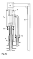
- FIG. 4 shows an advantageous variant of the cooling device according to the invention, in which a free neck or suspension tube 3c of the cryostat 1 via a line 23 open on both sides after thermal contact with the cold stages 11, 12 of the cold head 10 with the cavity 15a and thus also with the liquid tank 2a is connected.
- a connection can also be realized with a plurality of free neck or suspension tube 3c.
- the lines coming from the suspension tubes 3c are then first taken in a single line 23.
- This line 23 is then passed through the outer jacket 8 of the cooling device 7, which contains the cold head 10 and by means of the heat exchanger 24b, 24a with at least two cold stages 11, 12 of the cold head 10 and possibly also with a regenerator tube 25 above the coldest cold stage 12, z.
- the conduit 23 After contact with the coldest cold stage 12, the conduit 23 opens into the cavity 15a mounted on the cold head 10 or is guided along the metallic connection 17a into the liquid tank 2a for the cryogen 18a (helium).
- the gas located in the conduit 23 is cooled at the cold head 10 and liquefied at the coldest cold stage 12, so that due to the resulting suction, a flow in the conduit 23 through the suspension tube 3c toward the cooling device 7 is formed.
- the gas flow causes the suspension tube 3c is cooled by the heating gas and thus, ideally, the heat input via the suspension tube 3c completely compensated, or at least reduced.
- cryocooler decreases slightly due to the additional load, but the gain due to the lower incidence of heat is greater than the loss of cooling capacity.
- a less powerful cryocooler can be used.
- the heat transfer devices 14a, 14b heat pipes or cold fingers to make two or more parts, whereby they can be separated by means of gas-tight couplings (not shown). This makes a simpler installation and removal possible.
- a valve 26 and a pump 27 are provided in the conduit 23.
- a seal 30 When attached to the cryostat 1, a seal 30 must be provided.
- cooling device 7 is used for cooling a Kryostatan Aunt containing a superconducting magnet assembly 5, in particular, when the superconducting magnet assembly 5 is part of a nuclear magnetic resonance apparatus, in particular Magnetic Resonance Imaging (MRI) or Magnetic Resonance (NMR) spectroscopy. Accordingly, with the cooling device according to the invention, high-resolution NMR methods can be realized.
- MRI Magnetic Resonance Imaging
- NMR Magnetic Resonance
Landscapes
- Engineering & Computer Science (AREA)
- Physics & Mathematics (AREA)
- Mechanical Engineering (AREA)
- Thermal Sciences (AREA)
- General Engineering & Computer Science (AREA)
- Chemical & Material Sciences (AREA)
- Combustion & Propulsion (AREA)
- Containers, Films, And Cooling For Superconductive Devices (AREA)
Abstract
Description
Die Erfindung betrifft eine Kühlvorrichtung zur Rückverflüssigung von kryogenen Gasen, mit einem Außenmantel, der einen Vakuumraum begrenzt, und einem darin eingebauten Kaltkopf eines Kryokühlers, der mindestens zwei Kältestufen aufweist und der zumindest teilweise von einem Strahlungsschild umgeben ist.The invention relates to a cooling device for the re-liquefaction of cryogenic gases, with an outer shell defining a vacuum space, and a built-in cold head of a cryocooler having at least two cold stages and which is at least partially surrounded by a radiation shield.
Möglichkeiten zur kryogenverlustfreien Kühlung eines supraleitenden Magnetsystems mit einem Kryokühler werden zum Beispiel in EP0905436, EP0905524, WO03036207, WO03036190, US5966944, US5563566, US5613367, US5782095, US2002/000283, US2003/230089 beschrieben.Possibilities for the cryogenic loss-free cooling of a superconducting magnet system with a cryocooler are described, for example, in EP0905436, EP0905524, WO03036207, WO03036190, US5966944, US5563566, US5613367, US5782095, US2002 / 000283, US2003 / 230089.
Der beispielsweise zweistufige Kaltkopf des Kryokühlers ist üblicherweise in einem separaten, unter Vakuum stehenden Hüllrohr (wie z.B. in US5613376 beschrieben) oder direkt in den Vakuumraum eines Kryostaten (wie z.B. in US5563566 beschreiben) so eingebaut, dass die erste Kältestufe des Kaltkopfs fest mit einem Strahlungsschild und die zweite Kältestufe über eine feste Wärmebrücke oder direkt mit dem Heliumbehälter, wo sich der supraleitende Magnet in flüssigem Helium befindet, thermisch leitend verbunden werden. Durch Rückkondensation des durch Wärmeeinfall von außen verdampfenden Heliums an der kalten Kontaktfläche im Heliumbehälter kann der gesamte Wärmeeinfall auf den Heliumbehälter kompensiert und ein verlustfreier Betrieb des Systems ermöglicht werden. Alternativ hierzu kann der Kaltkopf in ein Halsrohr, welches die äußere Vakuumhülle des Kryostaten mit dem Heliumbehälter verbindet und entsprechend mit Heliumgas gefüllt ist, eingefügt werden, wie es beispielsweise in der Druckschrift US2002/ 0002830A1 beschrieben wird. Die erste Kältestufe des zweistufigen Kaltkopfes ist wiederum fest leitend mit einem Strahlungsschild kontaktiert, die zweite Kältestufe hängt frei in der Helium-Atmosphäre und verflüssigt direkt verdampftes Helium.The example two-stage cold head of the cryocooler is usually installed in a separate, vacuum-cladding tube (as described for example in US5613376) or directly into the vacuum space of a cryostat (as described for example in US5563566) so that the first cold stage of the cold head fixed with a radiation shield and the second cold stage is thermally conductively connected via a fixed thermal bridge or directly to the helium vessel where the superconductive magnet is in liquid helium. By recondensation of the helium evaporating by heat from the outside at the cold contact surface in the helium container, the entire heat input to the helium container can be compensated and a loss-free operation of the system can be made possible. Alternatively, the cold head may be inserted into a neck tube connecting the outer vacuum envelope of the cryostat to the helium vessel and correspondingly filled with helium gas, as described, for example, in US2002 / 0002830A1. The first cold stage of the two-stage cold head is again solidly contacted with a radiation shield, the second cold stage hangs freely in the helium atmosphere and liquefies directly evaporated helium.
Diese Varianten haben allerdings gewisse Nachteile: Der Aufbau und die Konstruktion des Kryostaten wird aufwändiger und komplizierter. Ferner führt der Einbau des zusätzlichen, den Kaltkopf des Kryokühlers aufnehmenden Hüllrohrs zu einem zusätzlichen Wärmeeintrag auf den Kaltkopf. Bei Verwendung eines zusätzlichen Halsrohres für den Kaltkopf kommt es durch Wärmeleitung in der Heliumgassäule und in der Rohrwand und unter Umständen durch Konvektionsströmungen im Heliumgas zu einem weiteren Wärmeeintrag auf den Heliumbehälter beziehungsweise den Kaltkopf des Kühlers. Außerdem können feste, starre oder auch flexibel ausgeführte, thermische Verbindungselemente zwischen Kaltkopf und Kryostaten Vibrationen des Kaltkopfes auf den Kryostaten übertragen. Da zudem im Regenerator der zweiten Stufe des Kaltkopfes von Kryokühlern, wie Pulsrohrkühlern oder Gifford-McMahon-Kühlern, im Temperaturbereich unter 10 K üblicherweise magnetische Regeneratormaterialien verwendet werden und der Regenerator sich unter Umständen relativ nahe am magnetischen Zentrum des NMR-Magnetsystems befindet, muss der Regenerator in der Regel abgeschirmt werden, so dass das Magnetfeld am Ort der NMR-Probe nicht gestört wird und umgekehrt die Funktion des Regenerators nicht beeinträchtigt wird. Schließlich stellt sich bei Ausfall des Kryokühlers ein instabiler Zustand ein, wobei sich vor allem die Temperaturen von Kryostat-Komponenten, wie z.B. dem Strahlungsschild, bis zu einem neuen Gleichgewichtszustand dauernd ändern. In einem Magnetsystem für hochauflösende Kernresonanzspektroskopie (NMR) kann das dazu führen, dass NMR-Messungen nicht mehr möglich werden, da sich der Shimzustand des Magneten fortlaufend ändert, oder dass im schlimmsten Fall der Magnet trocken läuft und quencht.However, these variants have certain disadvantages: The structure and construction of the cryostat becomes more complex and complicated. Furthermore, the installation of the additional, the cold head of the cryocooler receiving cladding leads to an additional heat input to the cold head. When using an additional neck tube for the cold head occurs by heat conduction in the helium gas column and in the pipe wall and possibly by convection in the helium gas to a further heat input to the helium tank or the cold head of the radiator. In addition, fixed, rigid or flexible thermal connection elements between the cold head and the cryostat can transmit vibrations of the cold head to the cryostat. In addition, because in the regenerator of the second stage of the cold head of cryocoolers, such as pulse tube coolers or Gifford-McMahon coolers, in the temperature range below 10 K usually magnetic regenerator materials are used and the regenerator may be relatively close to the magnetic center of the NMR magnet system, the regenerator must be shielded usually so that the magnetic field at the location of NMR sample is not disturbed and vice versa, the function of the regenerator is not affected. Finally, in case of failure of the cryocooler, an unstable state, in particular, the temperatures of cryostat components, such as the radiation shield, change constantly to a new equilibrium state. In a magnet system for high-resolution nuclear magnetic resonance (NMR) spectroscopy, this can mean that NMR measurements are no longer possible because the shim state of the magnet changes continuously or, in the worst case, the magnet runs dry and quenches.
Eine Methode, um einige dieser Nachteile zu vermeiden, und dennoch ein teilweise kryogenverlustfreies System zu realisieren, ist die Verwendung einer mit einem Kryokühler gekühlten Vorrichtung, die zur Rückverflüssigung eines einzelnen verdampften Kryogens eingesetzt werden kann. In einer bislang gebräuchlichen Kryostatanordnung für beispielsweise ein supraleitendes Magnetsystem wird der Magnet gewöhnlicherweise in einem mit flüssigem Helium von 4,2 K gefüllten Behälter eingebaut. Der He-Behälter ist in der Regel von einem abgasgekühlten Strahlungsschild und einem weiteren, mit flüssigem Stickstoff gekühlten Schild umgeben, so dass der Wärmeeintrag auf den Heliumbehälter von außen minimiert wird. Die passive Kühlung durch die verdampfenden Kryogene führt dazu, dass in gewissen Zeitabständen flüssiges Helium und Stickstoff nachgefüllt werden müssen.One way of avoiding some of these drawbacks while still achieving a partial cryogenic loss-free system is to use a cryocooler cooled device that can be used to re-liquefy a single vaporized cryogen. In a hitherto conventional cryostat arrangement for, for example, a superconducting magnet system, the magnet is usually installed in a container filled with liquid helium of 4.2 K. The He container is usually surrounded by an exhaust-cooled radiation shield and another, cooled with liquid nitrogen shield, so that the heat input is minimized to the helium container from the outside. Passive cooling by the evaporating cryogens causes liquid helium and nitrogen to be replenished at certain intervals.
In JP11257770 und JP2000283578 wird daher vorgeschlagen, in die vorhandenen Hals- oder Aufhängerohre eines Stickstoffbehälters einer Kryostatanordnung eine Wärme übertragende Vorrichtung in Gestalt eines Wärmerohrs einzuführen, das mit dem Kaltkopf eines Kryokühlers verbunden ist und verdampften Stickstoff wieder verflüssigt (siehe auch: Advances of Cryogenic Engineering, 45, 41-48). Dabei wird an den Kaltkopf des einstufigen Pulsrohrkühlers direkt der Verflüssiger angeflanscht. Dieser besteht aus einem dünnen Rohr, in welchem der Stickstoffdampf nach oben steigt, an einer mit dem Kaltkopf kontaktierten kalten Fläche verflüssigt wird und dann an der Rohrwand entlang nach unten läuft. Dieses sehr dünne, im oberen Teil noch von einer Vakuumhülle umgebene Rohr kann direkt in ein Stickstoff-Halsrohr oder ―Aufhängerohr eingeschoben werden und verhindert damit ein Abdampfen des Stickstoffs bzw. reduziert die Stickstoffverluste. Die Heliumverluste sind davon jedoch nicht betroffen, da lediglich der Stickstoff wieder verflüssigt wird.In JP11257770 and JP2000283578 it is therefore proposed to introduce into the existing neck or suspension tubes of a nitrogen container of a cryostat assembly a heat transfer device in the form of a heat pipe which is connected to the cold head of a cryocooler and liquefies vaporized nitrogen (see also: Advances of Cryogenic Engineering , 45, 41-48). Here, the condenser is flanged directly to the cold head of the single-stage pulse tube cooler. This consists of a thin tube in which the nitrogen vapor rises, is liquefied at a contacted with the cold head cold surface and then runs along the pipe wall down. This very thin, in the upper part still surrounded by a vacuum envelope tube can be inserted directly into a nitrogen neck tube or suspension tube and thus prevents evaporation of nitrogen or reduces nitrogen losses. However, the helium losses are not affected since only the nitrogen is liquefied again.
In ähnlicher Weise wurde auch die Rückverflüssigung von Helium für sich alleine in einem Aufbewahrungsbehälter für Helium mit dem zweistufigen Kaltkopf eines Kryokühlers schon durchgeführt.Similarly, the re-liquefaction of helium on its own in a helium storage vessel with the two-stage cold head of a cryocooler has already been carried out.
In beiden Fällen (Stickstoff- oder Helium-Verflüssiger) befindet sich der Kaltkopf des Kryokühlers in einem Außenmantel, der einen Vakuumraum begrenzt. Bei Verwendung von mehrstufigen Kryokühlern ist es üblich, dass Teile des Kaltkopfes von einem Strahlungsschild umgeben sind, der mit einer (aber nicht der kältesten) Kältestufe kontaktiert ist, so dass der Kaltkopf im Bereich tiefer Temperaturen gut gegen Wärmestrahlung isoliert ist.In both cases (nitrogen or helium liquefier), the cold head of the cryocooler is located in an outer jacket which limits a vacuum space. When using multi-stage cryocoolers, it is common that parts of the cold head are surrounded by a radiation shield, which is contacted with a (but not the coldest) cold stage, so that the cold head is well insulated against heat radiation in the low temperature range.
Wie schon oben erwähnt, weisen diverse konventionelle Kryostatanordnungen, wie sie speziell bei Magnetsystemen für hochauflösende Kernresonanzspektroskopie (NMR) zum Einsatz kommen, allerdings nicht nur ein Kryogen auf: neben einem mit flüssigem Helium gefüllten und den Magneten enthaltenden Behälter existiert zum Beispiel zusätzlich ein mit flüssigem Stickstoff gekühlter Strahlungsschild. Somit müsste man sowohl einen eigenen Helium-Verflüssiger als auch einen eigenen Stickstoff-Verflüssiger verwenden, wenn gleichzeitig die Verluste an Helium und Stickstoff reduziert werden sollen bzw. ein verlustfreier Betrieb erreicht werden soll. Dies würde einen erheblichen zusätzlichen apparativen Aufwand und höhere Investitions- und Betriebskosten bedeuten.However, as already mentioned above, various conventional cryostat arrangements, such as those used in magnetic systems for high-resolution nuclear magnetic resonance (NMR), do not have just one cryogen: in addition to a container filled with liquid helium and containing the magnet, for example, there is also a liquid Nitrogen cooled radiation shield. Thus, one would have to use both your own helium liquefier and its own nitrogen liquefier, if at the same time the losses of helium and nitrogen should be reduced or a loss-free operation should be achieved. This would mean a considerable additional expenditure on equipment and higher investment and operating costs.
Aufgabe der vorliegenden Erfindung ist es daher, eine Kühlvorrichtung bereitzustellen, mit der eine bestehende Kryostatanordnung, die mindestens zwei kryogene Flüssigkeiten enthält, insbesondere eine Kryostatanordnung, die eine supraleitende Magnetanordnung umfasst, ohne großen apparativen Aufwand und ohne zusätzliche Nachteile so nachgerüstet werden kann, dass nach außen keine oder zumindest nur geringere Verluste von einigen oder allen vorhandenen kryogenen Flüssigkeiten als üblich auftreten.It is therefore an object of the present invention to provide a cooling device with which an existing cryostat arrangement, which contains at least two cryogenic liquids, in particular a cryostat arrangement, which has a superconducting Magnet arrangement comprises, without great expenditure on equipment and without additional disadvantages can be retrofitted so that outwardly no or at least only minor losses of some or all existing cryogenic liquids occur as usual.
Ausgehend vom Stand der Technik wird diese Aufgabe erfindungsgemäß dadurch gelöst, dass mindestens zwei Kältestufen des Kaltkopfes des Kryokühlers für sich jeweils mit einer Wärme übertragenden Vorrichtung thermisch leitend verbunden sind, die jeweils in die Hals- oder Aufhängerohre eines Kryostaten zur Aufbewahrung von mindestens zwei verschiedenen kryogenen Flüssigkeiten eingeführt werden kann.Starting from the prior art, this object is achieved in that at least two cold stages of the cold head of the cryocooler for each thermally conductively connected to a heat transmitting device, each in the neck or suspension tubes of a cryostat for storage of at least two different cryogenic Liquids can be introduced.
Eine derartige Kühlvorrichtung bietet die folgenden Vorteile: Es lassen sich bestehende Kryostatanordnungen, und im Speziellen solche, die supraleitende Magnete enthalten, ohne (oder mit nur geringen) Anpassungen so nachrüsten, dass auch bei Verwendung mehrerer Kryogene mit einem geringen apparativen Aufwand ein kryogenverlustfreier Betrieb möglich wird. Es ist keine Neukonstruktion des Kryostaten notwendig. Der durch die Vorrichtung entstehende zusätzliche Wärmeeintrag in den Kryostaten ist bei geeigneter Konstruktion bescheiden und relativ genau voraussagbar. Die Wärme übertragenden Vorrichtungen, in denen die Verflüssigung der Kryogene stattfindet, sind so gestaltet, dass sie berührungslos in die Hals- oder Aufhängerohre der Kryostatanordnung eingeführt werden können. Das abdampfende Gas wird thermodynamisch effizient verflüssigt, da der Dampf nicht überhitzt wird und somit nicht erst wieder auf Verflüssigungstemperatur heruntergekühlt werden muss. Der Kaltkopf des Kryokühlers ist so weit vom magnetischen Zentrum einer in dem Kryostaten eingebauten supraleitenden Magnetanordnung entfernt, dass sich Störungen durch das magnetische Regeneratormaterial auf die Magnetanordnung viel weniger stark bemerkbar machen als wenn der Kaltkopf direkt in den Kryostaten integriert werden würde. Umgekehrt wird auch die Funktion des Kryokühlers durch das Magnetfeld der Magnetanordnung weniger beeinträchtigt. Fällt der Kryokühler aus oder muss er wegen Wartungsarbeiten ausgeschaltet werden, so erfüllt die Kryostatanordnung, wenn sie z.B. zur Kühlung einer supraleitenden Magnetanordnung verwendet wird, immer noch ihren Zweck, was eine hohe Betriebssicherheit gewährleistet. Zudem kann der Nutzer frei über die Betriebsweise (konventionell oder kryogenverlustfrei) bestimmen.Such a cooling device offers the following advantages: existing cryostat arrangements, and in particular those containing superconducting magnets, can be retrofitted without (or with only minor) adaptations so that cryogenic loss-free operation is possible even with the use of multiple cryogens with a low outlay on equipment becomes. No redesign of the cryostat is necessary. The additional heat input into the cryostat resulting from the device is modest and relatively predictable with suitable design. The heat transferring devices in which the liquefaction of the cryogens takes place are designed so that they can be introduced without contact into the neck or suspension tubes of the cryostat assembly. The evaporating gas is liquefied thermodynamically efficient, because the steam is not overheated and therefore does not have to be cooled down again to condensing temperature. The coldhead of the cryocooler is so far away from the magnetic center of a superconducting magnet assembly incorporated in the cryostat that disturbances from the magnetic regenerator material to the magnet assembly are much less noticeable than if the coldhead were integrated directly into the cryostat. Conversely, the function of the cryocooler is less affected by the magnetic field of the magnet assembly. If the cryocooler fails or has to be shut down for maintenance, the cryostat assembly, for example, when used to cool a superconducting magnet assembly, still serves its purpose ensures a high level of operational safety. In addition, the user can freely determine the mode of operation (conventional or cryogenic loss-free).
In einer besonders bevorzugten Ausführungsform der erfindungsgemäßen Kühlvorrichtung weist zumindest eine der Wärme übertragenden Vorrichtungen einen Hohlraum auf, der mit einer offenen Leitung, insbesondere einer Rohrleitung, verbunden ist. Durch die Leitung wird das aus dem Flüssigkeitstank des Kryostaten verdampfte Kryogen in den Hohlraum an der Kältestufe geführt, wo es verflüssigt wird. Das Kondensat fließt anschließend durch die Rohrleitung wiederum in den Flüssigkeitstank des Kryostaten zurück. In der Funktionsweise entspricht die Wärme übertragende Vorrichtung in dieser Form den aus der Wärmetechnik bekannten Wärmerohren.In a particularly preferred embodiment of the cooling device according to the invention, at least one of the heat-transferring devices has a cavity, which is connected to an open line, in particular a pipeline. Through the line, the cryogen vaporized from the liquid tank of the cryostat is led into the cavity at the cold stage, where it is liquefied. The condensate then flows back through the pipeline into the liquid tank of the cryostat. In operation, the heat transfer device in this form corresponds to the heat pipes known from heat technology.
In einer weiteren bevorzugten Ausführungsform der Erfindung weist zumindest eine der Wärme übertragenden Vorrichtungen eine metallische, die Wärme sehr gut leitenden Verbindung auf, an deren Ende aus dem Flüssigkeitstank des Kryostaten verdampftes Kryogen verflüssigt wird und anschließend wieder in das Flüssigkeitsbad des Flüssigkeitstanks des Kryostaten zurückfließt. Diese Verbindung wird am anderen Ende an eine Kältestufe des Kaltkopfes des Kryokühlers angeflanscht. Es sind beliebige Kombinationen der Wärme übertragenden Vorrichtungen möglich. So kann beispielsweise an die erste Kältestufe eines zweistufigen Kaltkopfes eine metallische die Wärme sehr gut leitende Verbindung angeflanscht werden, während die zweite Kältestufe mit einer Rohrleitung verbunden ist.In a further preferred embodiment of the invention, at least one of the heat-transferring devices has a metallic compound which conducts heat very well, liquefied at the end of which cryogen has evaporated from the liquid tank of the cryostat and then flows back again into the liquid bath of the liquid tank of the cryostat. This connection is flanged at the other end to a cold stage of the cold head of the cryocooler. Any combinations of the heat transferring devices are possible. Thus, for example, at the first cold stage of a two-stage cold head, a metallic connection which conducts the heat very well can be flanged, while the second cold stage is connected to a pipeline.
Insbesondere für hochauflösende NMR-Verfahren ist es vorteilhaft, wenn der Kryokühler ein Pulsrohrkühler ist, da Pulsrohrkühler besonders vibrationsarm betrieben werden können. Pulsrohrkühler sind ferner auch sehr betriebsicher und wartungsarm.In particular for high-resolution NMR methods, it is advantageous if the cryocooler is a pulse tube cooler, since pulse tube coolers can be operated with particularly low vibration. Pulse tube coolers are also very reliable and low maintenance.
Jedoch ist der Betrieb der Kühlvorrichtung auch sehr gut mit einem Gifford-McMahon-Kühler möglich. Ein Nachteil dieses Kryokühlers im Vergleich zu einem Pulsrohrkühler sind die größeren Vibrationen. Dieser Nachteil kommt dann nicht zum Tragen, wenn zwischen Kryokühler und Kryostatanordnung weiche Abdichtelemente verwendet werden, wie weiter unten beschrieben.However, the operation of the cooling device is also very well possible with a Gifford-McMahon cooler. A disadvantage of this cryocooler compared to a pulse tube cooler are the larger vibrations. This disadvantage does not apply if soft sealing elements are used between the cryocooler and the cryostat arrangement, as described below.
Besonders vorteilhaft ist es, wenn mindestens eine beidseitig offene Verbindungsleitung vorgesehen ist, über die der Kaltkopf des Kryokühlers mit mindestens einem Hals- oder Aufhängerohr des Flüssigkeitstanks mit dem tiefstsiedenden Kryogen, in die keine Wärme übertragende Vorrichtung eingeführt wird, verbunden werden kann, wobei die Leitung mit mindestens zwei Kältestufen des Kaltkopfes und unter Umständen auch mit einem Regeneratorrohr oberhalb der kältesten Kältestufe thermisch kontaktiert ist, und wobei die Leitung nach thermischen Kontakt mit der kältesten Kältestufe in den am Kaltkopf montierten Hohlraum mündet oder entlang der metallischen Verbindung in den Flüssigkeitstank geführt wird. Das sich in der Leitung befindende Gas wird am Kaltkopf des Kryokühlers abgekühlt und an der kältesten Kältestufe verflüssigt, so dass sich aufgrund des resultierenden Sogs eine Strömung in der Leitung durch die Hals- oder Aufhängerohre hin zur Kühlvorrichtung ausbildet. Die Gasströmung bewirkt, dass die Hals- oder Aufhängerohre durch das sich erwärmende Gas gekühlt werden und dadurch im Idealfall der Wärmeeintrag über die Hals- oder Aufhängerohre komplett kompensiert wird. Durch diese Umlaufströmung zur Kühlung von Hals- bzw. Aufhängerohren kann der Wärmeeintrag auf den Kryostaten weiter reduziert werden.It is particularly advantageous if at least one connecting line open on both sides is provided, via which the cold head of the cryocooler can be connected to at least one neck or suspension tube of the liquid tank with the cryogenic cryogen into which no heat transferring device is introduced is thermally contacted with at least two cold stages of the cold head and possibly also with a regenerator above the coldest cold stage, and wherein the conduit opens after thermal contact with the coldest cold stage in the cavity mounted on the cold head or is guided along the metallic compound in the liquid tank. The gas in the line is cooled at the cold head of the cryocooler and liquefied at the coldest cold stage, so that due to the resulting suction, a flow in the line through the neck or suspension tubes to the cooling device is formed. The gas flow causes the neck or suspension tubes to be cooled by the gas being heated, thereby ideally completely compensating for the heat input via the neck or suspension tubes. By means of this circulating flow for cooling neck or suspension tubes, the heat input to the cryostat can be further reduced.
Bei einer Weiterbildung dieser Ausführungsform ist in der Verbindungsleitung zwischen den Hals- oder Aufhängerohren und dem Kaltkopf ein Ventil und/oder eine Pumpe zur Regelung des Gasflusses vorgesehen. Hierdurch kann bei Bedarf der Gasstrom gedrosselt oder der optimale Gasfluss eingeregelt werden, wenn z. B. die Sogwirkung am Kaltkopf so groß ist, dass der Gasstrom größer wird als es für die optimale Kühlung der Aufhänge- oder Halsrohre ausreichend wäre.In a further development of this embodiment, a valve and / or a pump for regulating the gas flow is provided in the connecting line between the neck or suspension tubes and the cold head. As a result, if necessary, the gas flow throttled or the optimal gas flow can be adjusted when z. B. the suction effect on the cold head is so large that the gas flow is greater than it would be sufficient for the optimal cooling of the suspension or neck tubes.
Besonders vorteilhaft ist es, wenn an der kältesten Kältestufe des Kaltkopfes Helium bei einer Temperatur von 4,2 K oder bei tieferer Temperatur verflüssigt werden kann, da sich hierdurch eine Vielzahl an Einsatzmöglichkeiten im Tiefsttemperaturbereich bietet. Somit können der Helium-Verlust und die Nachfüllvorgänge reduziert werden bzw. kann bei genügend großer Kälteleistung des Kryokühlers ein verlustfreier Betrieb erreicht werden.It is particularly advantageous if helium can be liquefied at a temperature of 4.2 K or at a lower temperature at the coldest cold stage of the cold head, since this offers a multitude of possible uses in the lowest temperature range. Thus, the helium loss and the refilling operations can be reduced or can be achieved at sufficiently large cooling capacity of the cryocooler lossless operation.
Ein weiterer vorteilhafter Aspekt beinhaltet, dass an einer Kältestufe des Kaltkopfes des Kryokühlers flüssiger Stickstoff bei 77 K oder bei einer tieferen Temperatur erzeugt werden kann. Durch die Verwendung der Wärme übertragenden Vorrichtungen in einer Kryostatanordnung mit einem Behälter mit flüssigem Stickstoff können daher die Stickstoffverluste reduziert oder bei genügend großer Kälteleistung des Kryokühlers ein verlustfreier Betrieb erreicht werden.Another advantageous aspect involves that at a cold stage of the cold head of the cryocooler liquid nitrogen at 77 K or at a lower temperature can be generated. By using the heat transferring devices in a cryostat arrangement with a container of liquid nitrogen, therefore, the nitrogen losses can be reduced or loss-free operation can be achieved with sufficiently large cooling capacity of the cryocooler.
In einer vorteilhaften Ausführungsform wird eine Kältestufe des Kaltkopfes, welche nicht die kälteste ist, mit dem den Kaltkopf zumindest teilweise umgebenden Strahlungsschild thermisch leitend verbunden. Auf diese Weise wird der Wärmeeintrag durch Strahlung auf die kälteren Komponenten des Kaltkopfes wesentlich reduziert.In an advantageous embodiment, a cold stage of the cold head, which is not the coldest, is thermally conductively connected to the radiation shield at least partially surrounding the cold head. In this way, the heat input is substantially reduced by radiation to the colder components of the cold head.
Außerdem ist es von Vorteil, wenn die Wärme übertragende Vorrichtung zumindest teilweise innerhalb des Außenmantels der Kühlvorrichtung, also innerhalb des Vakuumraums, zu liegen kommt. Dies ist insbesondere für den Teil der Wärme übertragenden Vorrichtung relevant, der mit dem Kaltkopf des Kryokühlers verbunden ist. Somit ist dieser Teil der Wärme übertragenden Vorrichtung nach außen gegen Wärmeleitung sehr gut isoliert.Moreover, it is advantageous if the heat-transferring device at least partially comes to rest within the outer jacket of the cooling device, ie within the vacuum space. This is particularly relevant to the part of the heat transfer device which is connected to the cold head of the cryocooler. Thus, this part of the heat transfer device is very well insulated against heat conduction to the outside.
Des Weiteren ist es besonders vorteilhaft, wenn die Wärme übertragende Vorrichtung im Bereich außerhalb des Außenmantels zumindest teilweise von einem ersten Rohr umgeben ist. Dieses Rohr dient der Wärmeisolation der Wärme übertragenden Vorrichtung. Es kann, muss aber nicht über seine ganze Länge denselben Durchmesser aufweisen. So kann es zum Beispiel konstruktionsbedingt günstiger sein, für einen Teil des Rohres den kleinstmöglichen, für den Rest aber einen größeren Durchmesser zu wählen.Furthermore, it is particularly advantageous if the heat-transmitting device is at least partially surrounded by a first tube in the area outside the outer jacket. This tube serves to heat-isolate the heat-transferring device. It may or may not have the same diameter along its entire length. For example, it may be cheaper by design to choose the smallest possible part for one part of the pipe and a larger one for the rest.
In einer bevorzugten Ausführungsform ist dabei das die Wärme übertragende Vorrichtung umgebende erste Rohr an einem Ende offen und dort mit dem Vakuumraum des Außenmantels verbunden ist, während es am anderen Ende gasdicht mit der Rohrleitung oder der metallischen Verbindung der Wärme übertragenden Vorrichtung verbunden ist. Wird bei dieser Ausführungsform der Vakuumraum der Kühlvorrichtung evakuiert, so steht auch der vom ersten Rohr umgebene Teil der Wärme übertragenden Vorrichtung unter Vakuum. Die Wärme übertragende Vorrichtung ist dann in diesem Bereich sehr gut nach außen gegen Wärmeleitung isoliert.In a preferred embodiment, the first tube surrounding the heat-transferring device is open at one end and connected there to the vacuum space of the outer jacket, while at the other end it is gas-tightly connected to the pipeline or the metallic connection of the heat-transferring device. If the vacuum space of the cooling device is evacuated in this embodiment, the part of the heat-transmitting device surrounded by the first pipe is also under vacuum. The heat transferring device is then very well insulated in this area to the outside against heat conduction.
Bei einer anderen vorteilhaften Ausführungsform ist das die Wärme übertragende Vorrichtung umgebende erste Rohr an beiden Enden gasdicht mit der Rohrleitung oder der metallischen Verbindung der Wärme übertragenden Vorrichtung verbunden und über einen separaten Anschluss zur Evakuierung versehen. Der Innenraum des Rohres kann hierdurch evakuiert und der vom Rohr umgebene Teil der Wärme übertragenden Vorrichtung sehr gut nach außen gegen Wärmeleitung isoliert werden.In another advantageous embodiment, the first tube surrounding the heat-transferring device is connected in a gastight manner at both ends to the pipeline or the metallic connection of the heat-transferring device and provided with a separate connection for evacuation. The interior of the tube can thereby be evacuated and the part of the heat-transferring device surrounded by the tube can be isolated very well to the outside against heat conduction.
Besonders günstig ist es, wenn die Rohrleitung oder die metallische Verbindung der Wärme übertragenden Vorrichtung zumindest teilweise von einem weiteren, zweiten Rohr umgeben ist, welches mit dem Strahlungsschild thermisch leitend verbunden ist. Dieses Rohr ist innerhalb des ersten Rohres angeordnet, welches - wie eben beschreiben - der Vakuumisolierung dient. Auf diese Weise ist der vom zweiten Rohr umgebene Teil der Wärme übertragenden Vorrichtung sehr gut nach außen gegen Wärmestrahlung isoliert.It is particularly favorable if the pipeline or the metallic connection of the heat-transferring device is at least partially surrounded by a further, second tube, which is thermally conductively connected to the radiation shield. This tube is arranged within the first tube, which - as just described - the vacuum insulation is used. In this way, the part of the heat transferring device surrounded by the second tube is insulated very well from heat radiation.
Besonders vorteilhaft ist es, wenn die eben beschriebenen, die Wärme übertragende Vorrichtung umgebenden Rohre zumindest abschnittsweise flexibel, insbesondere als Balg, ausgeführt sind.It is particularly advantageous if the pipes described above, which surround the heat-transferring device, are at least partially flexible, in particular as bellows.
Zudem erweist es sich als sehr günstig, wenn auch die Wärme übertragende Vorrichtung zumindest abschnittsweise flexibel, insbesondere als Balg oder in Form von zu Litzen verflochtenen Drähten, ausgeführt ist. Somit kann eine Ausführungsform der erfindungsgemäßen Kühlvorrichtung realisiert werden, bei der die Wärme übertragende Vorrichtung mitsamt den sie umgebenden Rohren flexibel ist, was deren Einbau in die Hals- oder Aufhängerohre einer Kryostatanordnung wesentlich erleichtern kann.In addition, it proves to be very favorable, although the heat-transferring device is at least partially flexible, in particular as a bellows or in the form of interwoven wires to wires, is executed. Thus, an embodiment of the cooling device according to the invention can be realized, in which the heat-transferring device is flexible together with the surrounding tubes, which can facilitate their installation in the neck or suspension tubes of a Kryostatanordnung substantially.
In diesem Zusammenhang ist es ferner vorteilhaft, wenn sich die Wärme übertragende Vorrichtung und die sie umgebenden Rohre an mindestens einer Stelle mittels einer gasdichten Kupplung miteinander verbinden und voneinander trennen lassen. Die Kupplung ist so aufgebaut, dass die Funktionalität der Wärme übertragenden Vorrichtung mitsamt den sie umgebenden Rohren nicht beeinträchtigt wird. Hierdurch wird das Anbringen der Kühlvorrichtung an einer Kryostatanordnung wesentlich erleichtert.In this context, it is also advantageous if the heat-transferring device and the surrounding pipes connect to each other at least one location by means of a gas-tight coupling and separate from each other to let. The coupling is constructed so that the functionality of the heat transmitting device is not affected, including the surrounding pipes. As a result, the attachment of the cooling device is made much easier on a Kryostatanordnung.
In einer weiteren Ausführungsform der Erfindung ist es vorgesehen, dass die Kühlvorrichtung am Kryostaten zur Aufbewahrung kryogener Flüssigkeiten gasdicht befestigt werden kann. Dies kann entweder an den Hals- oder Aufhängerohren oder am Außenmantel der Kryostatanordnung ausgeführt sein.In a further embodiment of the invention, it is provided that the cooling device can be attached gas-tight to the cryostat for the storage of cryogenic liquids. This can be done either on the neck or suspension tubes or on the outer shell of the Kryostatanordnung.
Alternativ und bevorzugt kann die Kühlvorrichtung außerhalb des Kryostaten, z.B. an der Raumdecke oder an einem separaten Ständer, befestigt werden. Auf der Kryostatanordnung lastet dann nicht noch das Gewicht der Kühlvorrichtung. Dies erhöht unter Umständen die mechanische Stabilität der Kryostatanordnung.Alternatively, and preferably, the cooling device may be external to the cryostat, e.g. on the ceiling or on a separate stand, be attached. The weight of the cooling device then does not load on the cryostat arrangement. This may increase the mechanical stability of the cryostat assembly.
In diesem Zusammenhang ist es besonders vorteilhaft, wenn zur Abdichtung zwischen Kühlvorrichtung und Kryostat ein weiches, Vibrationen nicht übertragendes Verbindungselement vorgesehen ist. Auf diese Weise wird gewährleistet, dass - besonders für hochauflösende NMR-Verfahren - keine störenden beziehungsweise nur wenige Schwingungen der Kühlvorrichtung auf die Kryostatanordnung übertragen werden.In this context, it is particularly advantageous if a soft, vibration non-transmitting connecting element is provided for sealing between the cooling device and cryostat. In this way it is ensured that - especially for high-resolution NMR methods - no disturbing or only a few oscillations of the cooling device are transferred to the Kryostatanordnung.
Weiterhin ist es möglich, an den Kältestufen des Kaltkopfes des Kryokühlers elektrische Heizungen anzubringen. Bei einer Überschussleistung können die Heizungen so eingeregelt werden, dass der Kryokühler genau den Wärmeeinfall auf die verschiedenen Behälter der Kryostatanordnung kompensiert.Furthermore, it is possible to attach to the cold stages of the cold head of the cryocooler electric heaters. With an excess power, the heaters can be adjusted so that the cryocooler precisely compensates for the incidence of heat on the various containers of the Kryostatanordnung.
Die Vorteile der erfindungsgemäßen Kühlvorrichtung kommen besonders gut zur Geltung, wenn sie Teil einer Kryostatanordnung ist.The advantages of the cooling device according to the invention are particularly effective when it is part of a Kryostatanordnung.
Besonders vorteilhaft ist es, wenn die Kühlvorrichtung zur Kühlung einer supraleitenden Magnetanordnung dient, insbesondere wenn die supraleitende Magnetanordnung Teil einer Apparatur zur Kernspinresonanz, insbesondere Magnetic Resonance Imaging (MRI) oder Magnetresonanzspektroskopie (NMR) ist.It is particularly advantageous if the cooling device is used for cooling a superconducting magnet arrangement, in particular if the superconducting magnet arrangement is part of an apparatus for nuclear magnetic resonance, in particular magnetic resonance imaging (MRI) or magnetic resonance spectroscopy (NMR).
Schließlich ist es möglich, dass in einer mit der erfindungsgemäßen Kühlvorrichtung versehenen Kryostatanordnung über ein Hals- oder Aufhängerohr mindestens eines Flüssigkeitstanks eine elektrische Heizung in den Flüssigkeitstank eingeführt werden kann. Bei einer Überschussleistung des in der Kühlvorrichtung integrierten Kaltkopfes des Kryokühlers kann somit der Druck in den Flüssigkeitsbehältern über dem Umgebungsdruck und konstant gehalten werden. Es ist jedoch auch vorstellbar, dass die Leistung des Kryokühlers über seine Betriebsfrequenz und/ oder die Füllmenge an Arbeitsgas im Kryokühler geregelt wird.Finally, it is possible for an electrical heater to be introduced into the liquid tank via a neck or suspension tube of at least one liquid tank in a cryostat arrangement provided with the cooling device according to the invention. With an excess power of the cooling head integrated in the cold head of the cryocooler thus the pressure in the liquid containers above the ambient pressure and can be kept constant. However, it is also conceivable that the performance of the cryocooler is controlled by its operating frequency and / or the amount of working gas in the cryocooler.
Weitere Vorteile der Erfindung ergeben sich aus der Beschreibung und den Zeichnungen. Ebenso können die vorstehend genannten und die weiter aufgeführten Merkmale je für sich oder zu mehreren in beliebigen Kombinationen Verwendung finden. Die gezeigten und beschriebenen Ausführungsformen sind nicht als abschließende Aufzählung zu verstehen, sondern haben vielmehr beispielhaften Charakter für die Schilderung der Erfindung.Further advantages of the invention will become apparent from the description and the drawings. Likewise, the features mentioned above and those listed further can be used individually or in any combination. The embodiments shown and described are not to be understood as exhaustive enumeration, but rather have exemplary character for the description of the invention.
Es zeigen:
- Fig. 1
- eine Kryostatanordnung mit zwei Flüssigkeitstanks für kryogene Flüssigkeiten;
- Fig. 2a
- eine erfindungsgemäße Kühlvorrichtung mit Wärme übertragenden Vorrichtungen, die einen Hohlraum aufweisen;
- Fig. 2b
- eine erfindungsgemäße Kühlvorrichtung mit Wärme übertragenden Vorrichtungen, die eine metallische, die Wärme sehr gut leitende Verbindung aufweisen;
- Fig. 3
- eine in einen Kryostaten eingebaute Kühlvorrichtung gemäß Fig. 2a;
- Fig. 4
- eine in einen Kryostaten eingebaute Kühlvorrichtung gemäß der vorliegenden Erfindung mit einer Verbindungsleitung, die den Kaltkopf des Kryokühlers mit einem Aufhängerohre eines Flüssigkeitstanks verbindet;
- Fig. 5a
- eine am Kryostaten befestigte Kühlvorrichtung gemäß der vorliegenden Erfindung;
- Fig. 5b
- eine an der Raumdecke befestigte Kühlvorrichtung gemäß der vorliegenden Erfindung; und
- Fig. 5c
- eine an einem Ständer befestigte Kühlvorrichtung gemäß der vorliegenden Erfindung
- Fig. 1
- a cryostat assembly with two liquid tanks for cryogenic liquids;
- Fig. 2a
- a cooling device according to the invention with heat-transmitting devices having a cavity;
- Fig. 2b
- a cooling device according to the invention with heat-transmitting devices having a metallic, the heat very good conductive connection;
- Fig. 3
- a built in a cryostat cooling device of FIG. 2a;
- Fig. 4
- a cryostat integrated cooling device according to the present invention having a connection line connecting the cryocooler cold head to a suspension tube of a liquid tank;
- Fig. 5a
- a cryostat-mounted cooling device according to the present invention;
- Fig. 5b
- a ceiling-mounted refrigerator according to the present invention; and
- Fig. 5c
- a mounted on a stand cooling device according to the present invention
Fig. 1 zeigt eine schematische Darstellung eines Kryostaten 1 mit einer Magnetanordnung 5, wie er üblicher weise für MR-Anwendungen zum Einsatz kommt. Der Kryostat 1 umfasst einen mit Helium gefüllten Flüssigkeitstank 2a, der an Aufhängerohren 3a mit einem Außenmantel 4 des Kryostaten 1 verbunden ist, und in dem eine Magnetanordnung 5 angeordnet ist. Um den Flüssigkeitstank 2a ist ein weiterer Flüssigkeitstank 2b angeordnet, der Stickstoff enthält und an den Aufhängerohren 3b mit dem Außenmantel 4 des Kryostaten 1 verbunden ist. Der Flüssigkeitstank 2b mit Stickstoff ist thermisch mit den Aufhängerohren 3a kontaktiert. Zwischen den beiden Flüssigkeitstanks 2a, 2b ist ein abgasgekühlter Strahlungsschild 6 angeordnet, der wiederum mit den Aufhängerohren 3a thermisch kontaktiert ist. Fig. 1 shows a schematic representation of a cryostat 1 with a
Fig. 2a zeigt eine Ausführungsform einer erfindungsgemäßen Kühlvorrichtung 7. Die Kühlvorrichtung umfasst einen Außenmantel 8, der einen Vakuumraum 9 begrenzt, und einen darin eingebauten Kaltkopf 10 eines Kryokühlers, der mindestens zwei Kältestufen 11, 12 aufweist und der zumindest teilweise von einem Strahlungsschild 13 umgeben ist. Die Kältestufen 11, 12 des Kaltkopfes 10 sind jeweils mit einer Wärme übertragenden Vorrichtung 14a, 14b thermisch leitend verbunden. Die Wärme übertragenden Vorrichtungen 14a, 14b weisen jeweils einen Hohlraum 15a, 15b auf, wobei die Hohlräume 15a, 15b mit jeweils einer Rohrleitung 16a, 16b verbunden sind. FIG. 2 a shows an embodiment of a
Fig. 2b zeigt eine alternative Ausführungsform der erfindungsgemäßen Kühlvorrichtung 7, bei der die Wärme übertragenden Vorrichtungen 14a, 14b Verbindungen 17a, 17b aufweisen, welche Wärme sehr gut leiten können. Diese Verbindungen können beispielsweise in Form von Kaltfingern, die im Allgemeinen als Metallstäbe vorliegen, ausgeführt sein. Ein solcher Metallstab sollte eine größtmögliche Querschnittsfläche aufweisen, so dass die Temperaturdifferenz über den Stab möglichst klein bleibt. FIG. 2b shows an alternative embodiment of the
Die Rohrleitungen 16a, 16b können in die Aufhängerohre 3a, 3b von den Flüssigkeitstanks 2a, 2b eines Kryostaten 1 eingeführt werden. Fig. 3 zeigt eine erfindungsgemäße Kühlvorrichtung 7 im eingebauten Zustand. Die Rohrleitungen 16a, 16b befinden sich hier im Kryogendampf oberhalb der Flüssigkeitsoberfläche der in den Flüssigkeitstanks 2a, 2b befindlichen Kryogene 18a, 18b. Wie in Fig. 2a, 2b und 3 gezeigt, sind die Wärme übertragenden Vorrichtungen 14a, 14b jeweils mit einer Kältestufe 11, 12 des Kryokühlers thermisch leitend verbunden. Die aus den Flüssigkeitstanks 2a, 2b des Kryostaten 1 verdampften Kryogene 18a, 18b werden durch die Rohrleitungen 16a, 16b in den Hohlraum 15a, 15b an der jeweiligen Kältestufe 12, 11 geleitet, wo die Kryogene 18a, 18b kondensieren und somit verflüssigt werden, um anschließend durch die Rohrleitungen 16a, 16b wieder in die Flüssigkeitstanks 2a, 2b des Kryostaten 1 zurückzufließen. Alternativ kann der Heliumdampf auch am Ende einer metallischen, die Wärme sehr gut leitenden Verbindung 17a, 17b, die mit dem Kaltkopf 10 kontaktiert ist, verflüssigt werden, wie in Fig. 2b gezeigt.The
Dabei wird das bei höherer Temperatur siedende Kryogen 18b aus dem Flüssigkeitstank 2b an der ersten Kältestufe 11 des Kaltkopfes 10 verflüssigt, während die Verflüssigung des bei niedrigerer Temperatur siedenden Kryogens 18a an der zweiten, kälteren Kältestufe 12 des Kaltkopfes 10 stattfindet. Die Erfindung umfasst darüber hinaus auch Kühlvorrichtungen mit einem mehrstufigen Kaltkopf 10, so dass prinzipiell eine beliebige Anzahl an Kryogenen, entsprechend der Anzahl der Kältestufen des Kaltkopfes 10, verflüssigt werden kann.In this case, the cryogen 18b boiling at a higher temperature is liquefied from the
Um die Wärme übertragenden Vorrichtungen 14a, 14b gegenüber Wärmeeinfall zu isolieren, sind diese von einem ersten Rohr 19a, 19b umgeben, welches mit dem Vakuumraum 9 des Außenmantels 8 der Kühlvorrichtung 7 verbunden und zusammen mit dem Vakuumraum 9 evakuierbar ist (s. Fig. 2a, 2b). Zur Verbesserung der Wärmeisolation gegen von außen eindringende Wärmestrahlung ist innerhalb des ersten Rohres 19a ein zweites Rohr 20 angeordnet, welches mit dem Strahlungsschild 13 thermisch leitend verbunden ist. Der Durchmesser des ersten Rohres 19b ist in Fig. 2a, 2b und Fig. 3 nicht über die ganze Länge gleich. Es kann notwenig sein, dass das Rohr am geschlossenen Ende auf einen kleineren Durchmesser reduziert wird, damit es in das Aufhängerohr 3b des Flüssigkeitstanks 2b berührungslos eingeschoben werden kann. Um die Verbindung zwischen dem ersten Rohr 19b und dem Außenmantel 8 der Kühlvorrichtung 7 flexibel zu gestalten, ist diese als Balg ausgeführt. Zwischen dem ersten Rohr 19a und dem Außenmantel 8 und in einem Abschnitt des zweiten Rohrs 20 kann auch jeweils ein Balg eingefügt werden. Mit flexiblen Verbindungselementen 21a, 21b (wie zu Litzen verflochtener Draht) kann die in Fig. 2b gezeigte metallische Verbindung 17a, 17b beweglich gestaltet werden. Bei einer Überschussleistung des Kryokühlers können zusätzliche Heizungen (nicht gezeigt) an den Kältestufen 11, 12 des Kaltkopfes 10 des Kryokühlers angebracht werden. Alternativ oder ergänzend dazu kann, bei einer Überschussleistung des Kryokühlers, der Druck in den Flüssigkeitstanks 2a, 2b für die Kryogene 18a, 18b mit Heizungen 22a, 22b in den Flüssigkeitstanks 2a, 2b, die beispielsweise über noch freie Hals- oder Aufhängerohre 3c, 3d eingeführt werden, konstant gehalten werden.In order to insulate the heat-transferring
Fig. 4 zeigt eine vorteilhafte Variante der erfindungsgemäßen Kühlvorrichtung, bei der ein freies Hals- oder Aufhängerohr 3c des Kryostaten 1 über eine beidseitig offene Leitung 23 nach Wärmekontakt mit den Kältestufen 11, 12 des Kaltkopfes 10 mit dem Hohlraum 15a und somit auch mit dem Flüssigkeitstank 2a verbunden ist. Eine derartige Verbindung lässt sich auch mit mehreren freien Hals- oder Aufhängerohr 3c realisieren. Die von den Aufhängerohren 3c kommenden Leitungen werden dann zunächst in einer einzigen Leitung 23 gefasst. Diese Leitung 23 wird dann durch den Außenmantel 8 der Kühlvorrichtung 7, die den Kaltkopf 10 enthält, geführt und mittels der Wärmeübertrager 24b, 24a mit mindestens zwei Kältestufen 11, 12 des Kaltkopfes10 und unter Umständen auch mit einem Regeneratorrohr 25 oberhalb der kältesten Kältestufe 12, z. B. durch Umwicklung des Regeneratorrohres 25, thermisch kontaktiert. Nach Kontakt mit der kältesten Kältestufe 12 mündet die Leitung 23 in den am Kaltkopf 10 montierten Hohlraum 15a oder wird entlang der metallischen Verbindung 17a in den Flüssigkeitstank 2a für das Kryogen 18a (Helium) geführt. Das sich in der Leitung 23 befindende Gas wird am Kaltkopf 10 abgekühlt und an der kältesten Kältestufe 12 verflüssigt, so dass sich aufgrund des resultierenden Sogs eine Strömung in der Leitung 23 durch das Aufhängerohr 3c hin zur Kühlvorrichtung 7 ausbildet. Die Gasströmung bewirkt, dass das Aufhängerohr 3c durch das sich erwärmende Gas gekühlt wird und somit im Idealfall der Wärmeeintrag über das Aufhängerohr 3c komplett kompensiert, zumindest aber reduziert wird. Insgesamt nimmt die Leistung des Kryokühlers durch die zusätzlich Belastung zwar geringfügig ab, der Gewinn auf Grund des geringeren Wärmeeinfalls ist jedoch größer als der Verlust an Kälteleistung. Gerade für Systeme mit massiveren Hals- oder Aufhängerohren 3c kann so unter Umständen ein leistungsschwächerer Kryokühler verwendet werden. Es ist vorstellbar, die die Wärme übertragenden Vorrichtungen 14a, 14b (Wärmerohre bzw. Kaltfinger) zwei- oder mehrteilig zu gestalten, wodurch sie sich mittels gasdichten Kupplungen (nicht gezeigt) trennen lassen können. So wird ein einfacherer Ein- und Ausbau möglich. Um den Gasfluss durch die Leitung 23 zu regeln und dadurch einen optimalen Gasfluss zu erreichen, ist in der Leitung 23 ein Ventil 26 und eine Pumpe 27 vorgesehen. Prinzipiell ist es jedoch ausreichend, die Leitung 23 lediglich mit einer derartigen Vorrichtung (Ventil 26 oder Pumpe 27) auszustatten oder ganz ohne derartige Vorrichtungen zu belassen. Bei der in Fig. 4 vorgestellten Ausführungsform sind, wie auch bei der Ausführungsform gemäß Fig. 3, Heizungen 22a, 22b in den Flüssigkeitstank 2a, 2b vorgesehen. Aus Gründen der Übersichtlichkeit wurden in Fig. 4 jedoch die Anschlüsse nicht eingezeichnet. 4 shows an advantageous variant of the cooling device according to the invention, in which a free neck or
Fig. 5a bis 5c zeigen verschiedene Möglichkeiten für die Fixierung der Kühlvorrichtung 7. Der Vakuumbehälter, in dem sich der Kaltkopf 10 des Kryokühlers befindet, kann entweder am Außenmantel 4 des Kryostaten 1 direkt, wie in Fig. 5a gezeigt, oder extern, z.B. an der Raumdecke 28 (Fig. 5b) oder an einem separaten Ständer 29 (Fig. 5c) befestigt werden. Bei Befestigung am Kryostaten 1 muss eine Dichtung 30 vorgesehen werden. Zwischen dem Vakuumraum 9 und dem Außenmantel 4 des Kryostaten 1 werden bei externer Aufhängung nur noch weiche Abdichtelemente 31a, 31 b eingesetzt. Dies hat zur Folge, dass Vibrationen des Kryokühlers nicht oder nur sehr abgeschwächt auf den Kryostaten 1 übertragen werden. Dies erweist sich als besonders günstig, wenn die Kühlvorrichtung 7 zur Kühlung einer Kryostatanordnung eingesetzt wird, die eine supraleitende Magnetanordnung 5 enthält, insbesondere, wenn die supraleitende Magnetanordnung 5 Teil einer Apparatur zur Kernspinresonanz, insbesondere Magnetic Resonance Imaging (MRI) oder Magnetresonanzspektroskopie (Nuclear Magentic Resonance, NMR) ist. Mit der erfindungsgemäßen Kühlvorrichtung können demnach hochauflösenden NMR-Verfahren realisiert werden. 5a to 5c show various possibilities for fixing the
Zusammenfassend ergibt sich eine Kühlvorrichtung, die es erlaubt, bestehende Kryostatanordnungen, und im Speziellen solche, die supraleitende Magnete enthalten, ohne (oder mit nur geringen) Anpassungen so nachrüsten, dass auch bei Verwendung mehrerer Kryogene mit einem geringen apparativen Aufwand ein kryogenverlustfreier Betrieb möglich wird.In summary, results in a cooling device that allows existing Kryostatanordnungen, and in particular those containing superconducting magnets, without (or with only minor) adjustments so retrofit that even when using multiple cryogenics with a low equipment cost, a cryogenverlustfreier operation is possible ,
- 11
- Kryostatcryostat
- 2a, 2b2a, 2b
- Flüssigkeitstanksliquid tanks
- 3a, b, c, d3a, b, c, d
- Aufhängerohresuspension tubes
- 44
- Außenmantel des KryostatenOuter jacket of the cryostat
- 55
- Magnetanordnungmagnet assembly
- 66
- Strahlungsschild des KryostatenRadiation shield of the cryostat
- 77
- Kühlvorrichtungcooler
- 88th
- Außenmantel der KühlvorrichtungOuter jacket of the cooling device
- 99
- Vakuumraumvacuum space
- 1010
- Kaltkopfcold head
- 1111
- erste Kältestufefirst cold stage
- 1212
- zweite Kältestufesecond cold stage
- 1313
- Strahlungsschild der KühlvorrichtungRadiation shield of the cooling device
- 14a, b14a, b
- Wärme übertragenden VorrichtungHeat transferring device
- 15a, b15a, b
- Hohlraumcavity
- 16a, b16a, b
- Rohrleitungpipeline
- 17a, b17a, b
- Verbindungconnection
- 18a, b18a, b
- Kryogencryogenically
- 19a, b19a, b
- erstes Rohrfirst pipe
- 2020
- zweites Rohrsecond pipe
- 21a, b21a, b
- Verbindungselementconnecting element
- 22 a, b22 a, b
- Heizungheater
- 2323
- offene Leitungopen line
- 24a, b24a, b
- WärmeüberträgerHeat exchangers
- 2525
- Regeneratorrohrregenerator
- 2626
- VentilValve
- 2727
- Pumpepump
- 2828
- Raumdeckeceiling
- 2929
- Ständerstand
- 3030
- Dichtungpoetry
- 31a, b31a, b
- Abdichtelementesealing
Claims (26)
dadurch gekennzeichnet,
dass mindestens zwei Kältestufen (11, 12) des Kaltkopfes (10) für sich jeweils mit einer Wärme übertragenden Vorrichtung (14a, 14b) thermisch leitend verbunden sind, die jeweils in Hals- oder Aufhängerohre (3a, 3b) eines Kryostaten (1) zur Aufbewahrung von mindestens zwei verschiedenen kryogenen Flüssigkeiten (18a, 18b) eingeführt werden können.A cooling device (7) for the re-liquefaction of cryogenic gases, with an outer jacket (8) delimiting a vacuum space (9) and a built-in cold head (10) of a cryocooler having at least two cold stages (11, 12) and at least partially surrounded by a radiation shield (13),
characterized,
in that at least two cold stages (11, 12) of the cold head (10) are in each case thermally conductively connected to a heat-transmitting device (14a, 14b), each in neck or suspension tubes (3a, 3b) of a cryostat (1) Storage of at least two different cryogenic liquids (18a, 18b) can be introduced.
wobei die Leitung (23) mit mindestens zwei Kältestufen (11, 12) des Kaltkopfes (10) und unter Umständen auch mit einem Regeneratorrohr (25) oberhalb der kältesten Kältestufe (12) thermisch kontaktiert ist, und wobei die Leitung (23) nach thermischen Kontakt mit der kältesten Kältestufe (12) in den am Kaltkopf (10) montierten Hohlraum (15a) mündet oder entlang der metallischen Verbindung (17a) in den Flüssigkeitstank (2a) geführt wird.Cooling device (7) according to one of the preceding claims, characterized in that at least one open on both sides connecting line (23) is provided, via which the cold head (10) of the cryocooler with at least one neck or hanger ear (3c) of the liquid tank (2a) the low boiling cryogen (18a) into which no heat transferring device (14a) is introduced,
wherein the line (23) with at least two cold stages (11, 12) of the cold head (10) and possibly also with a regenerator tube (25) above the coldest cold stage (12) is thermally contacted, and wherein the conduit (23) by thermal Contact with the coldest cold stage (12) in the cold head (10) mounted cavity (15a) opens or along the metallic connection (17a) in the liquid tank (2a) is guided.
Applications Claiming Priority (1)
| Application Number | Priority Date | Filing Date | Title |
|---|---|---|---|
| DE102004037173A DE102004037173B3 (en) | 2004-07-30 | 2004-07-30 | Cryogenic cooler for workpiece incorporates cold head attached to two-stage cooler with attachments to sealed cryostat and with radiation shield inside vacuum-tight housing |
Publications (3)
| Publication Number | Publication Date |
|---|---|
| EP1628089A2 true EP1628089A2 (en) | 2006-02-22 |
| EP1628089A3 EP1628089A3 (en) | 2009-03-25 |
| EP1628089B1 EP1628089B1 (en) | 2012-05-23 |
Family
ID=35404600
Family Applications (1)
| Application Number | Title | Priority Date | Filing Date |
|---|---|---|---|
| EP05016144A Active EP1628089B1 (en) | 2004-07-30 | 2005-07-26 | Device for cooling of a cryostat arrangement |
Country Status (4)
| Country | Link |
|---|---|
| US (1) | US20070051116A1 (en) |
| EP (1) | EP1628089B1 (en) |
| JP (1) | JP2006046896A (en) |
| DE (1) | DE102004037173B3 (en) |
Cited By (3)
| Publication number | Priority date | Publication date | Assignee | Title |
|---|---|---|---|---|
| GB2492645A (en) * | 2011-07-04 | 2013-01-09 | Bruker Biospin Ag | Hermetically sealed cryocooler sleeve to avoid loss of cryogen during superconducting magnet quench |
| EP2821741A2 (en) | 2013-07-03 | 2015-01-07 | Bruker BioSpin AG | Method for retrofitting a cryostat assembly for circulation cooling |
| CN113903541A (en) * | 2021-11-04 | 2022-01-07 | 中国原子能科学研究院 | Large high-temperature superconducting magnetic system based on small refrigerator and temperature control method |
Families Citing this family (26)
| Publication number | Priority date | Publication date | Assignee | Title |
|---|---|---|---|---|
| JP2006116042A (en) * | 2004-10-21 | 2006-05-11 | Iwatani Industrial Gases Corp | Cooling unit in super-conductive magnet system |
| GB0523499D0 (en) * | 2005-11-18 | 2005-12-28 | Magnex Scient Ltd | Superconducting magnet systems |
| JP4814630B2 (en) * | 2005-12-21 | 2011-11-16 | 三菱電機株式会社 | Superconducting magnet system |
| JP4736047B2 (en) * | 2006-04-04 | 2011-07-27 | 学校法人金沢工業大学 | Cooling system |
| DE102007013350B4 (en) * | 2007-03-16 | 2013-01-31 | Bruker Biospin Ag | Power supply with high-temperature superconductors for superconducting magnets in a cryostat |
| JP4855990B2 (en) * | 2007-03-29 | 2012-01-18 | 株式会社東芝 | Recondensing device, mounting method thereof and superconducting magnet using the same |
| US20140123681A1 (en) * | 2007-04-02 | 2014-05-08 | General Electric Company | Method and apparatus to hyperpolarize materials for enhanced mr techniques |
| US20090301129A1 (en) * | 2008-06-08 | 2009-12-10 | Wang Nmr Inc. | Helium and nitrogen reliquefying apparatus |
| US20130045870A1 (en) * | 2010-05-04 | 2013-02-21 | Koninklijke Philips Electronics N.V. | Method and apparatus for shipping and storage of cryogenic devices |
| US9618257B2 (en) * | 2010-06-09 | 2017-04-11 | Quantum Design International, Inc. | Gas-flow cryostat for dynamic temperature regulation using a fluid level sensor |
| JP5728172B2 (en) | 2010-06-16 | 2015-06-03 | 株式会社神戸製鋼所 | Recondensing device and NMR analyzer equipped with the same |
| US8598881B2 (en) | 2011-01-11 | 2013-12-03 | General Electric Company | Magnetic resonance imaging system with thermal reservoir and method for cooling |
| CN102299022B (en) * | 2011-08-16 | 2013-11-06 | 南京丰盛超导技术有限公司 | Mechanical heat switch for refrigerating machine to directly cool superconducting magnet |
| KR101334321B1 (en) | 2012-05-15 | 2013-11-28 | 현대중공업 주식회사 | Cryocooler with the radiant heat shield |
| CN103697647B (en) * | 2012-09-28 | 2016-01-27 | 中国科学院物理研究所 | A kind of vacuum cryostat |
| CN103077797B (en) * | 2013-01-06 | 2016-03-30 | 中国科学院电工研究所 | For the superconducting magnet system of head imaging |
| KR101447525B1 (en) | 2013-11-06 | 2014-10-15 | 한국기초과학지원연구원 | Adiabatic collector for recycling gas, liquefier for recycling gas and recovery apparatus for recycling gas |
| JP5839734B2 (en) * | 2013-12-26 | 2016-01-06 | 大陽日酸株式会社 | Evaporative gas reliquefaction equipment for low temperature liquefied gas |
| CN104795198B (en) * | 2014-01-21 | 2018-02-13 | 西门子(深圳)磁共振有限公司 | A kind of cooling device of magnetic resonance imaging system, method and magnetic resonance imaging system |
| DE102015212314B3 (en) | 2015-07-01 | 2016-10-20 | Bruker Biospin Gmbh | Cryostat with active neck tube cooling by a second cryogen |
| DE102017130755A1 (en) | 2017-12-20 | 2019-06-27 | Bilfinger Noell Gmbh | Apparatus for analyzing an atmosphere and use of the apparatus |
| CN108657667A (en) * | 2018-07-06 | 2018-10-16 | 宁波健信核磁技术有限公司 | A kind of cold magnet transport container of superconduction |
| DE102019209160B3 (en) | 2019-06-25 | 2020-10-08 | Bruker Switzerland Ag | Cryostat arrangement with resilient, thermally conductive connecting element |
| JP7139303B2 (en) | 2019-11-01 | 2022-09-20 | ジャパンスーパーコンダクタテクノロジー株式会社 | Helium recondenser for cryostat |
| JP7366817B2 (en) * | 2020-03-23 | 2023-10-23 | 株式会社リコー | Helium circulation system, cryogenic freezing method, and biomagnetic measurement device |
| US11913714B2 (en) | 2021-11-02 | 2024-02-27 | Anyon Systems Inc. | Dilution refrigerator with continuous flow helium liquefier |
Citations (14)
| Publication number | Priority date | Publication date | Assignee | Title |
|---|---|---|---|---|
| US5563566A (en) | 1995-11-13 | 1996-10-08 | General Electric Company | Cryogen-cooled open MRI superconductive magnet |
| US5613367A (en) | 1995-12-28 | 1997-03-25 | General Electric Company | Cryogen recondensing superconducting magnet |
| US5613376A (en) | 1995-01-25 | 1997-03-25 | Matec S.R.L. | Thread cutting and aspiration unit for multiple-feed circular knitting machines |
| US5782095A (en) | 1997-09-18 | 1998-07-21 | General Electric Company | Cryogen recondensing superconducting magnet |
| EP0905436A2 (en) | 1997-09-30 | 1999-03-31 | Oxford Magnet Technology Limited | Load bearing means in NMR cryostat systems |
| EP0905524A1 (en) | 1997-09-30 | 1999-03-31 | Oxford Magnet Technology Limited | NMR magnet assembly with a neck tube housing a pulse tube refrigerator |
| JPH11257770A (en) | 1998-03-13 | 1999-09-24 | Sumitomo Heavy Ind Ltd | Liquid nitrogen recondenser |
| US5966944A (en) | 1997-04-09 | 1999-10-19 | Aisin Seiki Kabushiki Kaisha | Superconducting magnet system outfitted with cooling apparatus |
| JP2000283578A (en) | 1999-03-30 | 2000-10-13 | Sumitomo Heavy Ind Ltd | Liquefied gas storage unit, reliquefying unit, and reliquefying method for liquefied nitrogen |
| US20020000283A1 (en) | 2000-03-17 | 2002-01-03 | Jun Nakano | Transcribing method |
| US20020002830A1 (en) | 2000-07-08 | 2002-01-10 | Bruker Analytik Gmbh | Circulating cryostat |
| WO2003003620A1 (en) | 2001-06-29 | 2003-01-09 | Worldcom, Inc. | Method and system for programmable submarine network configuration plans to enable diverse service level agreements in telecommunication networks |
| WO2003036190A1 (en) | 2001-10-19 | 2003-05-01 | Oxford Magnet Technology Ltd. | A pulse tube refrigerator with an insulating sleeve |
| US20030230089A1 (en) | 2002-06-14 | 2003-12-18 | Bruker Biospin Gmbh | Cryostat configuration with improved properties |
Family Cites Families (15)
| Publication number | Priority date | Publication date | Assignee | Title |
|---|---|---|---|---|
| US3894403A (en) * | 1973-06-08 | 1975-07-15 | Air Prod & Chem | Vibration-free refrigeration transfer |
| US4223540A (en) * | 1979-03-02 | 1980-09-23 | Air Products And Chemicals, Inc. | Dewar and removable refrigerator for maintaining liquefied gas inventory |
| DE3471998D1 (en) * | 1983-04-15 | 1988-07-14 | Hitachi Ltd | Cryostat |
| JPS6138363A (en) * | 1984-07-31 | 1986-02-24 | 株式会社日立製作所 | Helium refrigerator |
| JPS6266067A (en) * | 1985-09-18 | 1987-03-25 | 株式会社日立製作所 | Helium cooling device |
| IT1198238B (en) * | 1986-12-23 | 1988-12-21 | Zambon Spa | COMPOUNDS WITH ANTIBIOTIC ACTIVITY |
| JPS63207958A (en) * | 1987-02-23 | 1988-08-29 | Toshiba Corp | Freezer |
| JPS63210572A (en) * | 1987-02-26 | 1988-09-01 | Toshiba Corp | Cryogenic freezer |
| US5327733A (en) * | 1993-03-08 | 1994-07-12 | University Of Cincinnati | Substantially vibration-free shroud and mounting system for sample cooling and low temperature spectroscopy |
| DE19548273A1 (en) * | 1995-12-22 | 1997-06-26 | Spectrospin Ag | NMR measuring device with pulse tube cooler |
| US5701744A (en) * | 1996-10-31 | 1997-12-30 | General Electric Company | Magnetic resonance imager with helium recondensing |
| US5936499A (en) * | 1998-02-18 | 1999-08-10 | General Electric Company | Pressure control system for zero boiloff superconducting magnet |
| US6038867A (en) * | 1998-07-31 | 2000-03-21 | General Electric Company | Wide multilayer insulating blankets for zero boiloff superconducting magnet |
| US6378312B1 (en) * | 2000-05-25 | 2002-04-30 | Cryomech Inc. | Pulse-tube cryorefrigeration apparatus using an integrated buffer volume |
| GB0125188D0 (en) * | 2001-10-19 | 2001-12-12 | Oxford Magnet Tech | A pulse tube refrigerator sleeve |
-
2004
- 2004-07-30 DE DE102004037173A patent/DE102004037173B3/en active Active
-
2005
- 2005-07-01 US US11/171,429 patent/US20070051116A1/en not_active Abandoned
- 2005-07-26 EP EP05016144A patent/EP1628089B1/en active Active
- 2005-07-29 JP JP2005220785A patent/JP2006046896A/en active Pending
Patent Citations (14)
| Publication number | Priority date | Publication date | Assignee | Title |
|---|---|---|---|---|
| US5613376A (en) | 1995-01-25 | 1997-03-25 | Matec S.R.L. | Thread cutting and aspiration unit for multiple-feed circular knitting machines |
| US5563566A (en) | 1995-11-13 | 1996-10-08 | General Electric Company | Cryogen-cooled open MRI superconductive magnet |
| US5613367A (en) | 1995-12-28 | 1997-03-25 | General Electric Company | Cryogen recondensing superconducting magnet |
| US5966944A (en) | 1997-04-09 | 1999-10-19 | Aisin Seiki Kabushiki Kaisha | Superconducting magnet system outfitted with cooling apparatus |
| US5782095A (en) | 1997-09-18 | 1998-07-21 | General Electric Company | Cryogen recondensing superconducting magnet |
| EP0905436A2 (en) | 1997-09-30 | 1999-03-31 | Oxford Magnet Technology Limited | Load bearing means in NMR cryostat systems |
| EP0905524A1 (en) | 1997-09-30 | 1999-03-31 | Oxford Magnet Technology Limited | NMR magnet assembly with a neck tube housing a pulse tube refrigerator |
| JPH11257770A (en) | 1998-03-13 | 1999-09-24 | Sumitomo Heavy Ind Ltd | Liquid nitrogen recondenser |
| JP2000283578A (en) | 1999-03-30 | 2000-10-13 | Sumitomo Heavy Ind Ltd | Liquefied gas storage unit, reliquefying unit, and reliquefying method for liquefied nitrogen |
| US20020000283A1 (en) | 2000-03-17 | 2002-01-03 | Jun Nakano | Transcribing method |
| US20020002830A1 (en) | 2000-07-08 | 2002-01-10 | Bruker Analytik Gmbh | Circulating cryostat |
| WO2003003620A1 (en) | 2001-06-29 | 2003-01-09 | Worldcom, Inc. | Method and system for programmable submarine network configuration plans to enable diverse service level agreements in telecommunication networks |
| WO2003036190A1 (en) | 2001-10-19 | 2003-05-01 | Oxford Magnet Technology Ltd. | A pulse tube refrigerator with an insulating sleeve |
| US20030230089A1 (en) | 2002-06-14 | 2003-12-18 | Bruker Biospin Gmbh | Cryostat configuration with improved properties |
Cited By (6)
| Publication number | Priority date | Publication date | Assignee | Title |
|---|---|---|---|---|
| GB2492645A (en) * | 2011-07-04 | 2013-01-09 | Bruker Biospin Ag | Hermetically sealed cryocooler sleeve to avoid loss of cryogen during superconducting magnet quench |
| GB2492645B (en) * | 2011-07-04 | 2016-12-14 | Bruker Biospin Ag | Cryostat |
| EP2821741A2 (en) | 2013-07-03 | 2015-01-07 | Bruker BioSpin AG | Method for retrofitting a cryostat assembly for circulation cooling |
| DE102013213020A1 (en) | 2013-07-03 | 2015-01-08 | Bruker Biospin Ag | Method for converting a cryostat arrangement to circulation cooling |
| CN113903541A (en) * | 2021-11-04 | 2022-01-07 | 中国原子能科学研究院 | Large high-temperature superconducting magnetic system based on small refrigerator and temperature control method |
| CN113903541B (en) * | 2021-11-04 | 2022-06-28 | 中国原子能科学研究院 | Large high-temperature superconducting magnetic system based on small refrigerator and temperature control method |
Also Published As
| Publication number | Publication date |
|---|---|
| EP1628089B1 (en) | 2012-05-23 |
| JP2006046896A (en) | 2006-02-16 |
| US20070051116A1 (en) | 2007-03-08 |
| EP1628089A3 (en) | 2009-03-25 |
| DE102004037173B3 (en) | 2005-12-15 |
Similar Documents
| Publication | Publication Date | Title |
|---|---|---|
| EP1628089B1 (en) | Device for cooling of a cryostat arrangement | |
| EP1628109B1 (en) | Cryostat arrangement | |
| DE102004053972B3 (en) | NMR spectrometer with common refrigerator for cooling NMR probe head and cryostat | |
| EP1736723B1 (en) | Cryostatic device with cryocooler | |
| DE102005041383B4 (en) | NMR apparatus with co-cooled probe head and cryocontainer and method of operation thereof | |
| DE69838866T2 (en) | Improvements in or related to cryostat systems | |
| DE102016218000B3 (en) | Cryostat arrangement with a vacuum container and an object to be cooled, with evacuable cavity | |
| DE10137552C1 (en) | Apparatus comprises cryo-generator consisting of cooling device having regenerator and pulse tube with heat exchangers arranged between them | |
| DE102004061869B4 (en) | Device for superconductivity and magnetic resonance device | |
| DE19914778B4 (en) | Superconducting magnet device | |
| EP2821741B1 (en) | Method for retrofitting a cryostat assembly for circulation cooling | |
| DE10033410C1 (en) | Kreislaufkryostat | |
| DE102016214731B3 (en) | NMR apparatus with superconducting magnet arrangement and cooled probe components | |
| DE102011078608B4 (en) | cryostat assembly | |
| DE69828128T2 (en) | Magnetic arrangement for nuclear magnetic resonance with a neck tube in which a pulse tube cooler is housed | |
| DE112011100875T5 (en) | Method and apparatus for controlling the temperature in a cryostat cooled to cryogenic temperatures using stagnant and moving gas | |
| DE60222920T2 (en) | SOCKET FOR PULSATION TUBE COOLING DEVICE | |
| EP1617157A2 (en) | Cryostatic device with cryocooler and gas slit heat exchanger | |
| DE102016214728B3 (en) | NMR apparatus with cooled probe head components insertable through a vacuum lock in the cryostats of a superconducting magnet assembly, and methods of assembling and removing same | |
| EP1504516B1 (en) | Superconductive device comprising a refrigeration unit, equipped with a refrigeration head that is thermally coupled to a rotating superconductive winding | |
| DE102014225481A1 (en) | Cryostat with a first and a second helium tank, which are separated liquid-tight from each other at least in a lower region | |
| DE10226498B4 (en) | Cryostat arrangement with improved properties | |
| EP3382411B1 (en) | Cryostatic device with a neck pipe with a load-bearing structure and an outer tube surrounding the load bearing structure for reducing cryogenic consumption | |
| EP3611528A1 (en) | Cryostat arrangement with superconducting magnetic coil system with thermal anchoring of the fixing structure | |
| EP1574777A2 (en) | System of supraconductor magnet with refrigerator |
Legal Events
| Date | Code | Title | Description |
|---|---|---|---|
| PUAI | Public reference made under article 153(3) epc to a published international application that has entered the european phase |
Free format text: ORIGINAL CODE: 0009012 |
|
| AK | Designated contracting states |
Kind code of ref document: A2 Designated state(s): AT BE BG CH CY CZ DE DK EE ES FI FR GB GR HU IE IS IT LI LT LU LV MC NL PL PT RO SE SI SK TR |
|
| AX | Request for extension of the european patent |
Extension state: AL BA HR MK YU |
|
| PUAL | Search report despatched |
Free format text: ORIGINAL CODE: 0009013 |
|
| AK | Designated contracting states |
Kind code of ref document: A3 Designated state(s): AT BE BG CH CY CZ DE DK EE ES FI FR GB GR HU IE IS IT LI LT LU LV MC NL PL PT RO SE SI SK TR |
|
| AX | Request for extension of the european patent |
Extension state: AL BA HR MK YU |
|
| 17P | Request for examination filed |
Effective date: 20090917 |
|
| AKX | Designation fees paid |
Designated state(s): CH DE FR GB LI |
|
| 17Q | First examination report despatched |
Effective date: 20110218 |
|
| GRAP | Despatch of communication of intention to grant a patent |
Free format text: ORIGINAL CODE: EPIDOSNIGR1 |
|
| RBV | Designated contracting states (corrected) |
Designated state(s): CH FR GB LI |
|
| GRAS | Grant fee paid |
Free format text: ORIGINAL CODE: EPIDOSNIGR3 |
|
| REG | Reference to a national code |
Ref country code: DE Ref legal event code: R108 Effective date: 20120229 |
|
| GRAA | (expected) grant |
Free format text: ORIGINAL CODE: 0009210 |
|
| AK | Designated contracting states |
Kind code of ref document: B1 Designated state(s): CH FR GB LI |
|
| REG | Reference to a national code |
Ref country code: GB Ref legal event code: FG4D Free format text: NOT ENGLISH |
|
| REG | Reference to a national code |
Ref country code: CH Ref legal event code: EP |
|
| PLBE | No opposition filed within time limit |
Free format text: ORIGINAL CODE: 0009261 |
|
| STAA | Information on the status of an ep patent application or granted ep patent |
Free format text: STATUS: NO OPPOSITION FILED WITHIN TIME LIMIT |
|
| 26N | No opposition filed |
Effective date: 20130226 |
|
| REG | Reference to a national code |
Ref country code: FR Ref legal event code: PLFP Year of fee payment: 12 |
|
| REG | Reference to a national code |
Ref country code: FR Ref legal event code: PLFP Year of fee payment: 13 |
|
| REG | Reference to a national code |
Ref country code: FR Ref legal event code: PLFP Year of fee payment: 14 |
|
| REG | Reference to a national code |
Ref country code: CH Ref legal event code: PFA Owner name: BRUKER SWITZERLAND AG, CH Free format text: FORMER OWNER: BRUKER BIOSPIN AG, CH |
|
| PGFP | Annual fee paid to national office [announced via postgrant information from national office to epo] |
Ref country code: GB Payment date: 20230724 Year of fee payment: 19 Ref country code: CH Payment date: 20230801 Year of fee payment: 19 |
|
| PGFP | Annual fee paid to national office [announced via postgrant information from national office to epo] |
Ref country code: FR Payment date: 20230724 Year of fee payment: 19 |
|
| P01 | Opt-out of the competence of the unified patent court (upc) registered |
Effective date: 20231220 |