EP1627992A2 - Méthode et dispositif pour la fabrication de moteurs à turbines à gaz - Google Patents
Méthode et dispositif pour la fabrication de moteurs à turbines à gaz Download PDFInfo
- Publication number
- EP1627992A2 EP1627992A2 EP05254611A EP05254611A EP1627992A2 EP 1627992 A2 EP1627992 A2 EP 1627992A2 EP 05254611 A EP05254611 A EP 05254611A EP 05254611 A EP05254611 A EP 05254611A EP 1627992 A2 EP1627992 A2 EP 1627992A2
- Authority
- EP
- European Patent Office
- Prior art keywords
- edge
- component
- shield
- adjacent
- positioning
- Prior art date
- Legal status (The legal status is an assumption and is not a legal conclusion. Google has not performed a legal analysis and makes no representation as to the accuracy of the status listed.)
- Granted
Links
Images


Classifications
-
- C—CHEMISTRY; METALLURGY
- C25—ELECTROLYTIC OR ELECTROPHORETIC PROCESSES; APPARATUS THEREFOR
- C25D—PROCESSES FOR THE ELECTROLYTIC OR ELECTROPHORETIC PRODUCTION OF COATINGS; ELECTROFORMING; APPARATUS THEREFOR
- C25D5/00—Electroplating characterised by the process; Pretreatment or after-treatment of workpieces
- C25D5/02—Electroplating of selected surface areas
-
- C—CHEMISTRY; METALLURGY
- C25—ELECTROLYTIC OR ELECTROPHORETIC PROCESSES; APPARATUS THEREFOR
- C25D—PROCESSES FOR THE ELECTROLYTIC OR ELECTROPHORETIC PRODUCTION OF COATINGS; ELECTROFORMING; APPARATUS THEREFOR
- C25D17/00—Constructional parts, or assemblies thereof, of cells for electrolytic coating
- C25D17/008—Current shielding devices
-
- F—MECHANICAL ENGINEERING; LIGHTING; HEATING; WEAPONS; BLASTING
- F01—MACHINES OR ENGINES IN GENERAL; ENGINE PLANTS IN GENERAL; STEAM ENGINES
- F01D—NON-POSITIVE DISPLACEMENT MACHINES OR ENGINES, e.g. STEAM TURBINES
- F01D5/00—Blades; Blade-carrying members; Heating, heat-insulating, cooling or antivibration means on the blades or the members
- F01D5/12—Blades
- F01D5/28—Selecting particular materials; Particular measures relating thereto; Measures against erosion or corrosion
- F01D5/288—Protective coatings for blades
-
- F—MECHANICAL ENGINEERING; LIGHTING; HEATING; WEAPONS; BLASTING
- F05—INDEXING SCHEMES RELATING TO ENGINES OR PUMPS IN VARIOUS SUBCLASSES OF CLASSES F01-F04
- F05D—INDEXING SCHEME FOR ASPECTS RELATING TO NON-POSITIVE-DISPLACEMENT MACHINES OR ENGINES, GAS-TURBINES OR JET-PROPULSION PLANTS
- F05D2230/00—Manufacture
- F05D2230/90—Coating; Surface treatment
Definitions
- This invention relates generally to turbine engines, and more specifically to environmental coatings used with turbine engine components.
- At least some known gas turbine engines include a forward fan, a core engine, and a power turbine.
- the core engine includes at least one compressor that provides pressurized air to a combustor wherein the air is mixed with fuel and ignited for generating hot combustion gases.
- the combustion gases flow downstream to one or more turbines that extract energy therefrom to power the compressor and provide useful work, such as powering an aircraft.
- a turbine section may include a stationary turbine nozzle positioned at the outlet of the combustor for channeling combustion gases into a turbine rotor disposed downstream thereof.
- the turbine nozzle may include a plurality of circumferentially spaced apart vanes.
- the vanes are impinged by the hot combustion gases exiting the combustor and are at least partially coated to facilitate protecting the vanes from the environment and to facilitate reducing wear.
- a platinum aluminide coating is be applied to turbine components, including the vanes to facilitate environmentally protecting the components.
- the application of platinum aluminide coatings is generally a three-step process that may include an electroplating process, a diffusion heat treatment, and an aluminiding process. During electroplating, platinum is plated over the surface of the component to be coated. Such that an electroplate coat of substantially uniform thickness is applied across the entire surface of the component.
- a magnetic field generated by current flow between the component to be coated and an anode used in coating may be non-uniformly distributed across the component, and more specifically such flux lines may be more dense adjacent sharp edges on the part, such as adjacent the trailing edge of the nozzle vane.
- a thicker coating of plating may be applied to such edges relative to the convex and concave surfaces of the airfoil portion of the vane.
- the uneven distribution of coatings may cause cracking:
- At least one known method of controlling the electroplate thickness adjacent the trailing edge requires that a disposable, metallic "robber" be positioned adjacent to the trailing edge to thieve current from the edge during the coating application.
- the effectiveness of the robber degrades over time and it may require frequent replacement.
- a method of fabricating a gas turbine engine component includes positioning a non-consumable shield adjacent to an edge of the component such that a gap is defined between the shield and the component, wherein the shield and gap form a fluid flow restriction adjacent to the edge, and inducing an electrical current from an anode to the component through an electrolyte bath such that a coating is applied to the component.
- an electroplating apparatus in another embodiment, includes an electroplating bath that includes an electrolytic solution, a power source, an anode coupled to the power source, a component coupled to the power source and immersed within the electrolytic solution wherein the component includes a plating surface bordered by an edge, and a non-consumable shield positioned adjacent to the component edge such that a gap is defined between the edge and the shield and wherein the shield and the gap form a fluid flow restriction adjacent to the edge.
- an electroplating apparatus in yet another embodiment of the invention, includes an electroplating bath including an electrolytic solution comprising platinum, a power source, an anode coupled to the power source, a component to be electroplated coupled to the power source and immersed within the electrolytic solution wherein the component includes a plating surface and an edge, and a non-consumable shield positioned adjacent to the edge such that a gap is defined between the edge and the shield and wherein the shield and the gap form a fluid flow restriction adjacent to the edge.
- the shield is configured to displace an electric field away from the edge to facilitate reducing an amount of electroplating deposited on the edge.
- the term "component” may include any component configured to be coupled with a gas turbine engine that may be coated with a metallic film coating, for example a high pressure turbine nozzle vane.
- a high pressure turbine nozzle vane is intended as exemplary only, and thus is not intended to limit in any way the definition and/or meaning of the term "component”.
- the invention is described herein in association with a gas turbine engine, and more specifically for use with a high pressure turbine nozzle vane for a gas turbine engine, it should be understood that the present invention is applicable to other gas turbine engine stationary components and rotatable components. Accordingly, practice of the present invention is not limited to high pressure turbine nozzle vanes for a gas turbine engine.
- Figure 1 is a longitudinal cross-sectional view of an exemplary high bypass ratio turbofan engine 10.
- Engine 10 includes, in serial axial flow communication about a longitudinal centerline axis 12, a fan 14, a booster 16, a high pressure compressor 18, a combustor 20, a high pressure turbine 22, and a low pressure turbine 24.
- High pressure turbine 22 is drivingly connected to high pressure compressor 18 with a first rotor shaft 26, and low pressure turbine 24 is drivingly connected to booster 16 and fan 14 with a second rotor shaft 28.
- ambient air passes through fan 14, booster 16, and compressor 18, the pressurized air stream enters combustor 20 where it is mixed with fuel and burned to provide a high energy stream of hot combustion gases.
- the high-energy gas stream passes through high-pressure turbine 22 to drive first rotor shaft 26.
- the gas stream passes through low-pressure turbine 24 to drive second rotor shaft 28, fan 14, and booster 16.
- Spent combustion gases exit out of engine 10 through an exhaust duct (not shown).
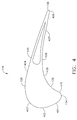
- FIG 2 is a perspective view of an exemplary first stage, high pressure turbine nozzle segment 114 that may be used with the gas turbine engine 10 (shown in Figure 1).
- High pressure turbine nozzle segment 114 may be positioned axially between combustor 20 and high pressure turbine 22 such that a row of first stage turbine rotor blades (not shown) is positioned downstream from high pressure turbine nozzle segment 114.
- a plurality of high pressure turbine nozzles 114 may be circumferentially spaced about axis 12 to form a high pressure turbine nozzle (not shown).
- High pressure turbine nozzle segment 114 includes at least one nozzle vane 118 coupled at opposite radial ends to a respective radially inner band 120 and a respective radially outer band 122.
- High pressure turbine nozzle segment 114 are typically formed in arcuate segments having two or more vanes 118 per segment 114. Vanes 118 may be cooled during operation against a flow of hot combustion gases 116 using a flow of cooling air 124 that may be channeled from, for example, a discharge of compressor 18 to individual vanes 118 through outer band 122.
- Each vane 118 includes a generally concave pressure sidewall 126, and a circumferentially opposite generally convex, suction sidewall 128.
- Sidewalls 126 and 128 may extend longitudinally in span along a radial axis of the nozzle between bands 120 and 122 wherein a root 130 couples to inner band 120 and a tip 132 couples to outer band 122.
- Sidewalks 126 and 128 extend chorale or axially between a leading edge 134 and an opposite trailing edge 136.
- FIG 3 is a perspective view of an exemplary electroplating process 200 for applying an electroplate coating to vanes 118 (shown in Figure 2).
- vane 118 may energized to a predetermined negative voltage with respect to a grid 202 such that when an electrolyte solution containing metal ions, for example, platinum covers a surface of vane 118, for example, sidewall 126, the metal ions in the electrolyte solution may be preferentially attracted to and bonded to sidewall 126 to form an electroplate coating 204.
- metal ions for example, platinum
- a non-conducting, non-consumable shield 206 is positioned adjacent trailing edge 136 such that a longitudinal axis 208 of shield 206 is substantially parallel to trailing edge 136 and separated by a gap 210 having a predetermined distance 212.
- distance 212 is approximately thirty mils. In an alternative embodiment, distance 212 is a distance greater than or less then thirty mils.
- shield 206 is fabricated from a non-conducting material, for example, plastic and has an outside diameter 218, for example, three-quarters inches, that is substantially greater than the thickness 220 of vane 118 at trailing edge 136.
- shield 206 may be formed to follow the contour of an irregularly shaped or curved edge while maintaining gap distance 212. Additionally, shield 206 may include an irregular cross-section, for example, shield 206 may be a hollow or solid and may include a groove or slot configured to be aligned with edge 136 for optimizing the flow restrictive gap distance 212 and/or the electrical characteristics of the electric field proximate gap distance 212.
- FIG 4 is a cross-sectional view of high pressure turbine nozzle vane 118 that may be used in electroplating process 200 (shown in Figure 3).
- Vane 118 includes concave pressure sidewall 126 and convex suction sidewall 128 that each extend axially between leading edge 134 and trailing edge 136.
- a plurality of thickness test locations are located at predetermined locations about a perimeter of vane 118 and are labeled 401-410.
- Figure 5 is a graph 500 of electroplate coating thickness readings taken at each of the plurality of test locations 401-410 (shown in Figure 4).
- Graph 500 includes an x-axis 502 whose units correlate with each respective test location, 401-410 (shown in Figure 4).
- electroplate coating thickness reading 401 is taken proximate leading edge 134
- electroplate coating thickness reading 406 is taken proximate trailing edge 136
- electroplate coating thickness readings 404 and 409 are taken proximate convex side 128 and proximate concave side 126 respectively.
- a y-axis 504 may be graduated in units of mils indicative of a thickness of a plating coating corresponding to the respective location, 401-410.
- a trace 506 joins points on graph 500 corresponding to an exemplary electroplate process for coating nozzle vane 118 with a metallic film coating.
- Trace 506 illustrates readings taken using the electroplate process wherein shield 206 is not utilized to form a flow restrictive gap distance 212 adjacent edge 136.
- Trace 506 illustrates a metallic film coating thickness at location 406 that is approximately 100% greater than the metallic film coating thickness at locations 401-405 and 407-410.
- a trace 508 illustrates readings taken at locations 401-410 after using the electroplate process wherein shield 206 is utilized to form a flow restrictive gap distance 212 adjacent edge 136 and to displace an electric field adjacent edge 136.
- Shield 206 facilitates plating a uniform metallic film coating thickness at locations 401-410.
- Trace 506 illustrates a metallic film coating thickness at location 406 that is approximately only 25% greater than the metallic film coating thickness at locations 401-405 and 407-410. Using shield 206 results in a more uniform metallic film coating thickness around the perimeter of vane 118.
- Trace 508 exhibits a thickness ratio of approximately 1.94, using the above formula, while trace 506 exhibits a thickness ratio of approximately 3.03, which represents a 40% improvement in uniformity of the metallic film coating thickness about the perimeter of vane 118.
- the above-described methods and apparatus are cost-effective and highly reliable for providing a substantially uniform metallic film coating thickness on gas turbine engine components, such as a high pressure turbine first stage nozzle.
- the shield positioned adjacent the edge of the nozzle vane to be coated defines an electrolyte flow restrictive gap and displaces a portion of the electric field adjacent the edge. Restricting the electrolyte flow adjacent the edge permits the electrolyte to be depleted in the gap and reduces the metallic ion concentration available for plating the edge. Displacing a portion of the electric field adjacent the edge facilitates reducing the electroplating motive force and thus, the rate of plating on the edge.
- the methods and apparatus facilitate fabrication of machines, and in particular gas turbine engines, in a cost-effective and reliable manner.
- electroplating methods and apparatus components are described above in detail.
- the components are not limited to the specific embodiments described herein, but rather, components of each apparatus may be utilized independently and separately from other components described herein.
- Each electroplating method and apparatus component can also be used in combination with other electroplating methods and apparatus components.
Landscapes
- Chemical & Material Sciences (AREA)
- Engineering & Computer Science (AREA)
- Materials Engineering (AREA)
- Metallurgy (AREA)
- Organic Chemistry (AREA)
- Chemical Kinetics & Catalysis (AREA)
- Electrochemistry (AREA)
- Mechanical Engineering (AREA)
- General Engineering & Computer Science (AREA)
- Electroplating Methods And Accessories (AREA)
- Turbine Rotor Nozzle Sealing (AREA)
- Electrical Discharge Machining, Electrochemical Machining, And Combined Machining (AREA)
- Electrodes For Compound Or Non-Metal Manufacture (AREA)
Applications Claiming Priority (1)
| Application Number | Priority Date | Filing Date | Title |
|---|---|---|---|
| US10/921,502 US20060037865A1 (en) | 2004-08-19 | 2004-08-19 | Methods and apparatus for fabricating gas turbine engines |
Publications (3)
| Publication Number | Publication Date |
|---|---|
| EP1627992A2 true EP1627992A2 (fr) | 2006-02-22 |
| EP1627992A3 EP1627992A3 (fr) | 2012-08-22 |
| EP1627992B1 EP1627992B1 (fr) | 2014-06-11 |
Family
ID=34981358
Family Applications (1)
| Application Number | Title | Priority Date | Filing Date |
|---|---|---|---|
| EP05254611.6A Expired - Fee Related EP1627992B1 (fr) | 2004-08-19 | 2005-07-25 | Méthode pour la fabrication de moteurs à turbines à gaz |
Country Status (5)
| Country | Link |
|---|---|
| US (2) | US20060037865A1 (fr) |
| EP (1) | EP1627992B1 (fr) |
| JP (1) | JP4912638B2 (fr) |
| CN (1) | CN1746338B (fr) |
| SG (3) | SG140592A1 (fr) |
Cited By (2)
| Publication number | Priority date | Publication date | Assignee | Title |
|---|---|---|---|---|
| EP1916388A2 (fr) * | 2006-10-18 | 2008-04-30 | United Technologies Corporation | Vanne dotée d'un transfert de chaleur amélioré |
| EP2573201A3 (fr) * | 2011-09-23 | 2013-08-14 | General Electric Company | Procédé de remise à neuf de revêtement PtAl sur matériaux de turbine retirée du service |
Families Citing this family (5)
| Publication number | Priority date | Publication date | Assignee | Title |
|---|---|---|---|---|
| US20060275624A1 (en) * | 2005-06-07 | 2006-12-07 | General Electric Company | Method and apparatus for airfoil electroplating, and airfoil |
| FR2954780B1 (fr) | 2009-12-29 | 2012-02-03 | Snecma | Procede de depot par voie electrolytique d'un revetement composite a matrice metallique contenant des particules, pour la reparation d'une aube metallique |
| DE102010047906B4 (de) * | 2010-10-11 | 2014-09-11 | MTU Aero Engines AG | Verfahren zur elektrochemischen partiellen Beschichtung eines Bauteils sowie Vorrichtung |
| KR101495419B1 (ko) * | 2013-04-10 | 2015-02-24 | 주식회사 포스코 | 에지 과도금을 방지하기 위한 전기도금장치 |
| CA2866479C (fr) * | 2013-12-20 | 2021-08-17 | Will N. Kirkendall | Electroplacage de composant de turbine interne |
Citations (5)
| Publication number | Priority date | Publication date | Assignee | Title |
|---|---|---|---|---|
| US4426266A (en) * | 1983-02-28 | 1984-01-17 | Kawasaki Steel Corporation | Strip edge overcoating preventing device for continuous electroplating |
| JPH02232393A (ja) * | 1989-03-06 | 1990-09-14 | Furukawa Electric Co Ltd:The | 差厚メッキ方法およびその装置 |
| JPH10110292A (ja) * | 1996-10-04 | 1998-04-28 | Nippon Steel Corp | エッジオーバーコート防止装置 |
| JP2002220690A (ja) * | 2001-01-29 | 2002-08-09 | Dowa Mining Co Ltd | 電気メッキ方法および装置 |
| US20020179450A1 (en) * | 2001-05-31 | 2002-12-05 | International Business Machines Corporation | Selective shield/material flow mechanism |
Family Cites Families (28)
| Publication number | Priority date | Publication date | Assignee | Title |
|---|---|---|---|---|
| US3891515A (en) * | 1973-03-23 | 1975-06-24 | Electro Coatings | Method for plating aircraft cylinders |
| JPS5841358B2 (ja) * | 1980-01-12 | 1983-09-12 | 株式会社小糸製作所 | メツキ装置 |
| US4534832A (en) * | 1984-08-27 | 1985-08-13 | Emtek, Inc. | Arrangement and method for current density control in electroplating |
| JPS62166261A (ja) * | 1986-01-16 | 1987-07-22 | Matsushita Electric Ind Co Ltd | 温風暖房機 |
| JPS6381866A (ja) * | 1986-09-25 | 1988-04-12 | Mitsubishi Electric Corp | 半導体装置の製造方法 |
| US4879007B1 (en) * | 1988-12-12 | 1999-05-25 | Process Automation Int L Ltd | Shield for plating bath |
| JPH0334064A (ja) * | 1989-06-30 | 1991-02-14 | Fujitsu Ltd | 間違い電話防止方式 |
| US5328572A (en) * | 1991-02-20 | 1994-07-12 | Ibbott Jack Kenneth | Dual system using three electrodes to treat fluid |
| DE4106733A1 (de) * | 1991-03-02 | 1992-09-03 | Schering Ag | Vorrichtung zum abblenden von feldlinien in einer galvanikanlage (iii) |
| US5608186A (en) * | 1992-01-27 | 1997-03-04 | Thomas & Betts Corporation | Ground rod |
| US5277785A (en) * | 1992-07-16 | 1994-01-11 | Anglen Erik S Van | Method and apparatus for depositing hard chrome coatings by brush plating |
| CN1104688A (zh) * | 1994-09-22 | 1995-07-05 | 肖禹 | 一种强制镀铁修复曲轴的方法 |
| EP0718420B1 (fr) * | 1994-12-24 | 1999-04-21 | Rolls Royce Plc | Revêtement de barrière thermique et méthode pour l'appliquer sur un article en superalliage |
| FR2750438B1 (fr) * | 1996-06-27 | 1998-08-07 | Usinor Sacilor | Procede et installation de revetement electrolytique par une couche metallique de la surface d'un cylindre pour coulee continue de bandes metalliques minces |
| US5985123A (en) * | 1997-07-09 | 1999-11-16 | Koon; Kam Kwan | Continuous vertical plating system and method of plating |
| DE19736352C1 (de) * | 1997-08-21 | 1998-12-10 | Atotech Deutschland Gmbh | Vorrichtung zur Kontaktierung von flachem Behandlungsgut in Durchlaufgalvanisieranlagen |
| DE19845506A1 (de) * | 1998-10-02 | 2000-04-06 | Wieland Edelmetalle | Verfahren zur Herstellung von prothetischen Formteilen für den Dentalbereich und prothetisches Formteil |
| US6402923B1 (en) * | 2000-03-27 | 2002-06-11 | Novellus Systems Inc | Method and apparatus for uniform electroplating of integrated circuits using a variable field shaping element |
| US6946065B1 (en) * | 1998-10-26 | 2005-09-20 | Novellus Systems, Inc. | Process for electroplating metal into microscopic recessed features |
| US6632335B2 (en) * | 1999-12-24 | 2003-10-14 | Ebara Corporation | Plating apparatus |
| DE10061186C1 (de) * | 2000-12-07 | 2002-01-17 | Astrium Gmbh | Verfahren und Anordnung zur galvanischen Abscheidung von Nickel, Kobalt, Nickellegierungen oder Kobaltlegierungen mit periodischen Strompulsen und Verwendung des Verfahrens |
| JPWO2003008850A1 (ja) * | 2001-07-19 | 2004-11-11 | ニッタ・ムアー株式会社 | 耐熱性樹脂チューブ |
| US6861355B2 (en) * | 2002-08-29 | 2005-03-01 | Micron Technology, Inc. | Metal plating using seed film |
| US6802950B2 (en) * | 2002-11-26 | 2004-10-12 | Sandia National Laboratories | Apparatus and method for controlling plating uniformity |
| US7547478B2 (en) * | 2002-12-13 | 2009-06-16 | General Electric Company | Article including a substrate with a metallic coating and a protective coating thereon, and its preparation and use in component restoration |
| CN2618928Y (zh) * | 2003-04-28 | 2004-06-02 | 宝山钢铁股份有限公司 | 边缘罩 |
| US7604726B2 (en) * | 2004-01-07 | 2009-10-20 | Honeywell International Inc. | Platinum aluminide coating and method thereof |
| US20060275624A1 (en) * | 2005-06-07 | 2006-12-07 | General Electric Company | Method and apparatus for airfoil electroplating, and airfoil |
-
2004
- 2004-08-19 US US10/921,502 patent/US20060037865A1/en not_active Abandoned
-
2005
- 2005-07-25 EP EP05254611.6A patent/EP1627992B1/fr not_active Expired - Fee Related
- 2005-08-12 SG SG200801118-1A patent/SG140592A1/en unknown
- 2005-08-12 SG SG2011057692A patent/SG174064A1/en unknown
- 2005-08-12 SG SG200505160A patent/SG120268A1/en unknown
- 2005-08-18 JP JP2005237367A patent/JP4912638B2/ja not_active Expired - Fee Related
- 2005-08-19 CN CN2005100939294A patent/CN1746338B/zh not_active Expired - Fee Related
-
2013
- 2013-01-04 US US13/734,703 patent/US20130186763A1/en not_active Abandoned
Patent Citations (5)
| Publication number | Priority date | Publication date | Assignee | Title |
|---|---|---|---|---|
| US4426266A (en) * | 1983-02-28 | 1984-01-17 | Kawasaki Steel Corporation | Strip edge overcoating preventing device for continuous electroplating |
| JPH02232393A (ja) * | 1989-03-06 | 1990-09-14 | Furukawa Electric Co Ltd:The | 差厚メッキ方法およびその装置 |
| JPH10110292A (ja) * | 1996-10-04 | 1998-04-28 | Nippon Steel Corp | エッジオーバーコート防止装置 |
| JP2002220690A (ja) * | 2001-01-29 | 2002-08-09 | Dowa Mining Co Ltd | 電気メッキ方法および装置 |
| US20020179450A1 (en) * | 2001-05-31 | 2002-12-05 | International Business Machines Corporation | Selective shield/material flow mechanism |
Cited By (4)
| Publication number | Priority date | Publication date | Assignee | Title |
|---|---|---|---|---|
| EP1916388A2 (fr) * | 2006-10-18 | 2008-04-30 | United Technologies Corporation | Vanne dotée d'un transfert de chaleur amélioré |
| EP1916388A3 (fr) * | 2006-10-18 | 2013-10-30 | United Technologies Corporation | Vanne dotée d'un transfert de chaleur amélioré |
| EP2573201A3 (fr) * | 2011-09-23 | 2013-08-14 | General Electric Company | Procédé de remise à neuf de revêtement PtAl sur matériaux de turbine retirée du service |
| US8636890B2 (en) | 2011-09-23 | 2014-01-28 | General Electric Company | Method for refurbishing PtAl coating to turbine hardware removed from service |
Also Published As
| Publication number | Publication date |
|---|---|
| SG140592A1 (en) | 2008-03-28 |
| JP2006057179A (ja) | 2006-03-02 |
| EP1627992A3 (fr) | 2012-08-22 |
| SG174064A1 (en) | 2011-09-29 |
| SG120268A1 (en) | 2006-03-28 |
| CN1746338B (zh) | 2012-04-25 |
| US20060037865A1 (en) | 2006-02-23 |
| US20130186763A1 (en) | 2013-07-25 |
| CN1746338A (zh) | 2006-03-15 |
| JP4912638B2 (ja) | 2012-04-11 |
| EP1627992B1 (fr) | 2014-06-11 |
Similar Documents
| Publication | Publication Date | Title |
|---|---|---|
| US20130186763A1 (en) | Methods for fabricating gas turbine engines | |
| US8739404B2 (en) | Turbine components with cooling features and methods of manufacturing the same | |
| EP2578720B1 (fr) | Procédés de réparation de composants refroidis | |
| US8672613B2 (en) | Components with conformal curved film holes and methods of manufacture | |
| US9938899B2 (en) | Hot gas path component having cast-in features for near wall cooling | |
| US20160363052A1 (en) | Hot gas path component cooling system having a particle collection chamber | |
| EP2619443B1 (fr) | Paroi d'élément refroidie dans un moteur à turbine | |
| US20100062180A1 (en) | Method of repairing a coating on an article | |
| US8636890B2 (en) | Method for refurbishing PtAl coating to turbine hardware removed from service | |
| US10738622B2 (en) | Components having outer wall recesses for impingement cooling | |
| US9752440B2 (en) | Turbine component having surface cooling channels and method of forming same | |
| US20100062151A1 (en) | Method of repairing an aluminide coating on an article | |
| US9126278B2 (en) | Template for forming cooling passages in a turbine engine component | |
| EP3040514A1 (fr) | Composant de moteur à turbine à gaz et procédés associés de fabrication et de réparation | |
| WO2019074514A1 (fr) | Composants revêtus ayant des ouvertures de refroidissement adaptatives et leurs procédés de fabrication | |
| US10533439B2 (en) | Gas turbine engine component with abrasive surface formed by electrical discharge machining | |
| US11000909B2 (en) | Electrical discharge machining electrode | |
| US20150008140A1 (en) | Method for fabricating microchannels in fluid cooled components |
Legal Events
| Date | Code | Title | Description |
|---|---|---|---|
| PUAI | Public reference made under article 153(3) epc to a published international application that has entered the european phase |
Free format text: ORIGINAL CODE: 0009012 |
|
| AK | Designated contracting states |
Kind code of ref document: A2 Designated state(s): AT BE BG CH CY CZ DE DK EE ES FI FR GB GR HU IE IS IT LI LT LU LV MC NL PL PT RO SE SI SK TR |
|
| AX | Request for extension of the european patent |
Extension state: AL BA HR MK YU |
|
| PUAL | Search report despatched |
Free format text: ORIGINAL CODE: 0009013 |
|
| AK | Designated contracting states |
Kind code of ref document: A3 Designated state(s): AT BE BG CH CY CZ DE DK EE ES FI FR GB GR HU IE IS IT LI LT LU LV MC NL PL PT RO SE SI SK TR |
|
| AX | Request for extension of the european patent |
Extension state: AL BA HR MK YU |
|
| RIC1 | Information provided on ipc code assigned before grant |
Ipc: C25D 7/06 20060101ALI20120718BHEP Ipc: C25D 5/16 20060101ALI20120718BHEP Ipc: F01D 5/28 20060101AFI20120718BHEP Ipc: C25D 17/00 20060101ALI20120718BHEP |
|
| 17P | Request for examination filed |
Effective date: 20130222 |
|
| AKX | Designation fees paid |
Designated state(s): DE FR GB |
|
| GRAP | Despatch of communication of intention to grant a patent |
Free format text: ORIGINAL CODE: EPIDOSNIGR1 |
|
| INTG | Intention to grant announced |
Effective date: 20140116 |
|
| GRAS | Grant fee paid |
Free format text: ORIGINAL CODE: EPIDOSNIGR3 |
|
| GRAA | (expected) grant |
Free format text: ORIGINAL CODE: 0009210 |
|
| AK | Designated contracting states |
Kind code of ref document: B1 Designated state(s): DE FR GB |
|
| REG | Reference to a national code |
Ref country code: GB Ref legal event code: FG4D |
|
| REG | Reference to a national code |
Ref country code: DE Ref legal event code: R096 Ref document number: 602005043860 Country of ref document: DE Effective date: 20140724 |
|
| REG | Reference to a national code |
Ref country code: DE Ref legal event code: R097 Ref document number: 602005043860 Country of ref document: DE |
|
| PLBE | No opposition filed within time limit |
Free format text: ORIGINAL CODE: 0009261 |
|
| STAA | Information on the status of an ep patent application or granted ep patent |
Free format text: STATUS: NO OPPOSITION FILED WITHIN TIME LIMIT |
|
| 26N | No opposition filed |
Effective date: 20150312 |
|
| REG | Reference to a national code |
Ref country code: DE Ref legal event code: R097 Ref document number: 602005043860 Country of ref document: DE Effective date: 20150312 |
|
| REG | Reference to a national code |
Ref country code: FR Ref legal event code: PLFP Year of fee payment: 11 |
|
| PGFP | Annual fee paid to national office [announced via postgrant information from national office to epo] |
Ref country code: DE Payment date: 20150729 Year of fee payment: 11 Ref country code: GB Payment date: 20150727 Year of fee payment: 11 |
|
| PGFP | Annual fee paid to national office [announced via postgrant information from national office to epo] |
Ref country code: FR Payment date: 20150717 Year of fee payment: 11 |
|
| REG | Reference to a national code |
Ref country code: DE Ref legal event code: R119 Ref document number: 602005043860 Country of ref document: DE |
|
| GBPC | Gb: european patent ceased through non-payment of renewal fee |
Effective date: 20160725 |
|
| PG25 | Lapsed in a contracting state [announced via postgrant information from national office to epo] |
Ref country code: FR Free format text: LAPSE BECAUSE OF NON-PAYMENT OF DUE FEES Effective date: 20160801 Ref country code: DE Free format text: LAPSE BECAUSE OF NON-PAYMENT OF DUE FEES Effective date: 20170201 |
|
| REG | Reference to a national code |
Ref country code: FR Ref legal event code: ST Effective date: 20170331 |
|
| PG25 | Lapsed in a contracting state [announced via postgrant information from national office to epo] |
Ref country code: GB Free format text: LAPSE BECAUSE OF NON-PAYMENT OF DUE FEES Effective date: 20160725 |