EP1627697B1 - Formwerkzeug zur Herstellung eines Profils, Profilierungsvorrichtung, und Anwendung des Formwerkzeugs - Google Patents
Formwerkzeug zur Herstellung eines Profils, Profilierungsvorrichtung, und Anwendung des Formwerkzeugs Download PDFInfo
- Publication number
- EP1627697B1 EP1627697B1 EP20050291694 EP05291694A EP1627697B1 EP 1627697 B1 EP1627697 B1 EP 1627697B1 EP 20050291694 EP20050291694 EP 20050291694 EP 05291694 A EP05291694 A EP 05291694A EP 1627697 B1 EP1627697 B1 EP 1627697B1
- Authority
- EP
- European Patent Office
- Prior art keywords
- central
- profile
- rollers
- roller
- depth
- Prior art date
- Legal status (The legal status is an assumption and is not a legal conclusion. Google has not performed a legal analysis and makes no representation as to the accuracy of the status listed.)
- Expired - Lifetime
Links
Images




Classifications
-
- B—PERFORMING OPERATIONS; TRANSPORTING
- B21—MECHANICAL METAL-WORKING WITHOUT ESSENTIALLY REMOVING MATERIAL; PUNCHING METAL
- B21D—WORKING OR PROCESSING OF SHEET METAL OR METAL TUBES, RODS OR PROFILES WITHOUT ESSENTIALLY REMOVING MATERIAL; PUNCHING METAL
- B21D5/00—Bending sheet metal along straight lines, e.g. to form simple curves
- B21D5/06—Bending sheet metal along straight lines, e.g. to form simple curves by drawing procedure making use of dies or forming-rollers, e.g. making profiles
- B21D5/08—Bending sheet metal along straight lines, e.g. to form simple curves by drawing procedure making use of dies or forming-rollers, e.g. making profiles making use of forming-rollers
- B21D5/083—Bending sheet metal along straight lines, e.g. to form simple curves by drawing procedure making use of dies or forming-rollers, e.g. making profiles making use of forming-rollers for obtaining profiles with changing cross-sectional configuration
Definitions
- Document is known US-B-4006617 a tool for forming a profile with depth variation along its length.
- This tool has a pair of lower side rollers secured to a lower drive shaft.
- a lower central roll is disposed between these two side rollers in a vertically movable manner.
- the tool further includes a pair of upper side rollers. Between these two upper rollers is disposed an upper central roll which is integral with an upper drive shaft.
- the lower central roll and the upper side rollers each comprise a central bore whose diameter is greater than the diameter of the respective shaft, to allow a radial and vertical mobility of the central rollers relative to the side rollers.
- the lower central roll and the upper side rollers are each held together by a U-shaped holding flange.
- this tool is complex because of the presence of the many holding flanges.
- the holding flanges must be individually servocontrolled to control the tool, resulting in an expensive control installation.
- the invention aims to overcome these disadvantages by providing a tool that has a simpler and more economical construction.
- the invention therefore relates to a tool of the aforementioned type, characterized in that the control means of the central rollers comprise a cage which maintains said central rollers relative to each other and which keeps the two central rollers relative to each other. to the support.
- the invention also relates to a profiling machine of the type comprising at least one pair of formation rollers, from the strip, of a profile having a bottom provided with at least one lateral edge extended by a wing and whose depth is constant and substantially equal to the minimum depth of the profile to obtain, characterized in that it comprises a forming tool as defined above.
- the machine comprises one or more of the following characteristics.
- the bending shoe is provided with a bending aperture having a cross section which includes a portion corresponding to the variable depth portion of the profile, and in that the height of the portion is equal to the depth difference of the profile.
- the invention also relates to the use of a tool as cited above for manufacturing a profile having a variable depth along its length.
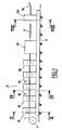
- FIG. 1 schematically shows a continuous manufacturing facility of a profile with local depth variations.
- This installation comprises a reel of a reel 2 of a metal strip 1 and means for continuously driving the strip 1 in a profiling machine, designated as a whole by the reference numeral 10.
- This profiling machine 10 comprises a frame 11 and, mounted on this frame 11, a succession of pairs of rollers for performing in a single pass and continuously a local depth variation profile.
- the profile at the output of the profiling machine comprises a bottom provided with at least one lateral edge extended by a wing.
- each branch is extended by a wing.
- the profiling machine 10 comprises, first of all, two pairs of rollers, respectively 12 and 13, which make it possible to produce a section 3 ( Fig. 3 ) U-shaped constant depth and having a bottom 3a, two side edges 3b each extended by a wing 3c.
- the first pair of rollers 12 shown in FIG. Fig. 2 comprises, in a conventional manner, upper rollers formed by two lateral rollers 14 and a central roller 15 and lower rollers formed by two lateral rollers 16 and a central roller 17.
- the upper rollers 14 and 15 are mounted integral in rotation on a shaft 18 and the lower rollers are mounted integral in rotation on a shaft 19.
- the strip 1 flows between the upper rollers 14 and 15 and the lower rollers 16 and 17 and, to form the U-shaped section 3, the central roll 15 has a diameter greater than the diameter of the lateral rollers 14 and the central roll 17 a a diameter smaller than the diameter of the lateral rollers 16.
- the second pair of rollers 13 is identical to the first pair of rollers 12, the only difference residing in the fact that the central roll has a larger diameter than the diameter of the central roll of the first pair of rollers so as to form a profile 3 U-shaped whose depth is substantially equal to the minimum depth of the local depth variation profile to obtain, as will be seen later.
- rollers of the two pairs of rollers 12 and 13 are rotated in a synchronized manner.
- the profiling machine 10 may comprise a pair of rollers 12 or 13 to form the profile 3 according to the desired section and to the desired minimum depth.
- the profiling machine 10 comprises, downstream of the pair of rollers 13 with respect to the forward direction of the strip 1, a forming tool 20 whose active part is movable perpendicular to the direction of advance of the profile 3 at the exit of the second pair of rollers 13 so as to modify the depth of portions of this section 3. For example, it is possible to produce a profile comprising at least a portion of length of increasing depth or at least a portion of length of increasing depth followed a portion of length decreasing in depth.
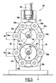
- the forming tool 20 mounted on the frame 11 of the profiling machine 10 consists of an upper horizontal axis 40 disposed above the plane of travel of the profile 3.
- the axis 40 supports two lateral cylindrical rollers 41 which are integral with this axis.
- a central cylindrical roller 42 is mounted freely in rotation and in vertical translation on the axis 40.
- the central roller 42 has an axial orifice 42a of diameter greater than the diameter of the axis 40.
- the forming tool 20 also comprises a lower horizontal axis 43 disposed below the running plane of the profile 3 and supporting two rollers Lateral cylindrical cylinders 44.
- a central cylindrical roller 45 is mounted freely in rotation and in vertical translation on the lower axis 43.
- the central roller 45 comprises, for this purpose, an axial orifice 45a of diameter greater than the diameter of the axis 43.
- the central roller 42 has a diameter D1
- the central roller 45 has a diameter D2.
- the diameters D1 and D2 are identical (see Figure 5 ).
- the lateral rollers 41 and 44 maintain the wings 3c of the profile 3 and the central rollers 42 and 45 are movable simultaneously and perpendicular to the direction of advance of this section 3 by control means 50 controlled so as to form a section 4 comprising portions of constant depth and portions of increasing or decreasing depth ( Fig. 7 ).
- the means 50 for vertical translation control of the central rollers 42 and 45 are formed by a single cage 51, comprising a first arcuate portion 51a holding the upper central roller 42 by means of guide rollers 55a mounted free in rotation in said first portion 51a, a second arcuate portion 51b holding the central roller 45 by means of guide rollers 55b rotatably mounted in said second portion 51b and brackets 52.
- the guide rollers 51a have a diameter D3, while the guide rollers 51b have a diameter D4.
- the diameter D4 is identical to the diameter D3 in this embodiment.
- the ends of the two parts 51a and 51b of the cage 51 are fixed to each other by stirrups 52 of such that the cage 51 maintains vertical central rollers 42 and 45 which are also maintained transversely by the lateral rollers, respectively 41 and 44.
- the cage 51 transmits the vertical movement to the central rollers 42 and 45.
- the means 50 for controlling the vertical displacement of the central rollers 42 and 45 via the cage 51 and the guide rollers 55a, 55b are controlled for example by a single jack 56, hydraulic or pneumatic, supported by a support frame 57 integral with the frame of the profiling machine and whose control rod 56a is connected to the cage 51 to move the central rollers 42 and 45 perpendicular to the direction of advance of the profile 3.
- the lateral rollers 41 and 44 are rotated synchronously respectively by the axes 40 and 43. It should be noted that the axes 40 and 43 are fixed in translation relative to the frame 57, and are only rotatable around their respective axes. This is a particularly simple structure to manufacture.
- the lateral rollers 41 and 44 maintain the wings 3c of this profile 3 while flat portions or portions of increasing and decreasing depth are formed on the bottom 3b of said profile 3 by moving the central rollers 42 and 45 through the cage 51 and guide rollers 55 driven by the jack 56.
- the bottom of the section 4 obtained may comprise a first flat portion a6, a second portion a7 of increasing depth, a third flat portion a8, a fourth portion a9 decreasing depth and a last portion a10 plane.
- the profile thus has a total height H and a depth variation ⁇ h on the length of the profile.
- the forming tool 20 allows to form on the bottom 3a of the profile 3 a succession of planar portions and portions of increasing and decreasing depth by driving the jack 56 according to the shape of the profile to be obtained.
- the central rollers 42 and 45 can be rotated by the side rollers 41 and 44 corresponding by means of a suitable system.
- the profiling machine 10 comprises, downstream of the forming tool 20 with respect to the forward direction of the profile 3, at least one pair of planing rollers of the flanges and the bottom of the profile 4.
- the profiling machine 10 comprises a first assembly 70 planing the wings of the profile 4 and a second assembly 80 of leveling of the bottom of this profile 4.
- the wings of the profile 4 can be cut and this section 4 is cut into sections 5 by a cutting system 90 of known type.
- the profiling machine 10 comprises a bending device 100 of the section sections 5, located downstream of the cutting system 90.
- This bending device 100 is adapted to bend a profile having a variable depth along its length.
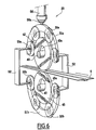
- the device 100 comprises a bending shoe 102 provided with a bending aperture 104 having a cross section which is identical to the projection of the profile 5 in its longitudinal direction.
- the opening 104 comprises two inverted L-shaped side portions 106, 108 and a rectangular central portion 110 connecting the two parts 106, 108.
- the height of the portion 110 is substantially equal to the difference in depth ⁇ h of the profile section 5.
- the profile obtained has a curved shape 5A.
- This tool 20 comprises an upper central roller 42 having a diameter D1 greater than the diameter D2 of the lower central roller 45.
- the upper guide rollers 55a have a diameter D3 which is smaller than the diameter D4 of the lower guide rollers 55b.
- the leveling of the bottom and the wings of the profile can be achieved in the forming tool 20 simultaneously with the formation of the portions of variable depth.
- the profile obtained at the output of the profiling machine may have a U-shaped section or a section having a bottom provided with a lateral edge extended by a wing or a bottom provided with two lateral edges of different heights.
- the manufacturing installation according to the invention thus makes it possible to carry out continuously and in a single pass a local depth variation profile comprising a succession of depth portions. constant and portions of increasing and decreasing depth.
- the profile thus obtained can be used as a bodywork element of a motor vehicle, such as for example to form an amount, a frame, a door anti-intrusion reinforcement or a bumper or as a structural element such as a spar or a crossbeam or as a structural framing element.
- the profile obtained can be steel or aluminum or aluminum alloy.
Landscapes
- Engineering & Computer Science (AREA)
- Mechanical Engineering (AREA)
- Bending Of Plates, Rods, And Pipes (AREA)
Claims (12)
- Formwerkzeug (20) zur fortlaufenden Herstellung eines Profils (3, 4) mit variabler lokaler Tiefe, vom Typ umfassend- einen Träger (57),- eine erste zentrale zylindrische Laufrolle (42), die über einer Scrollebene des Profils (3, 4) angeordnet und frei in Übertragung bezüglich des Trägers (57) angebracht ist,- eine zweite zentrale zylindrische Laufrolle (45), die unter der Scrollebene des Profils (3, 4) angeordnet und frei in Übertragung bezüglich des Trägers angebracht ist,- wobei die zentralen Laufrollen (42; 45) durch gesteuerte Antriebsmittel (50) gleichzeitig senkrecht in Vorwärtsrichtung des Profils (3, 4) verschiebbar sind, dadurch gekennzeichnet, dass die Antriebsmittel (50) der zentralen Laufrollen (42; 45) einen Korb (51) umfassen, der die zentralen Laufrollen (42; 45) im Verhältnis zueinander hält und der die beiden zentralen Laufrollen (42, 45) im Verhältnis zu dem Träger (57) hält.
- Werkzeug nach Anspruch 1, dadurch gekennzeichnet, dass die Antriebsmittel (50) einen Zylinder (56) umfassen, dessen Antriebsbolzen (56a) mit dem Korb (51) verbunden ist, um die zentralen Laufrollen (42; 45) gleichzeitig senkrecht in der Vorwärtsrichtung des Profils (3) im Verhältnis zu dem Träger (57) zu verschieben.
- Werkzeug nach einem der vorstehenden Ansprüche, dadurch gekennzeichnet, dass die erste zentrale Laufrolle (42) und die zweite zentrale Laufrolle (45) gleiche Umfänge (D1, D2) besitzen.
- Werkzeug nach einem der Ansprüche 1 oder 2, dadurch gekennzeichnet, dass die erste zentrale Laufrolle (42) und die zweite zentrale Laufrolle (45) verschiedene Umfänge (D1, D2) besitzen.
- Werkzeug nach Anspruch 4, dadurch gekennzeichnet, dass die erste zentrale Laufrolle (42) einen Durchmesser (D1) besitzt, der größer ist als der Durchmesser (D2) der zweiten zentralen Laufrolle (45).
- Werkzeug nach einem der Ansprüche 1 bis 5, dadurch gekennzeichnet, dass der Korb (51) Rollen zur Führung (55a, 55b) umfasst, die dafür ausgelegt sind, die ersten und zweiten zentralen Laufrollen (42, 45) zu führen.
- Werkzeug nach den zusammengenommenen Ansprüchen 5 und 6, dadurch gekennzeichnet, dass die Rollen zur Führung (55a), die die erste Laufrolle (42) führen, einen Durchmesser (D3) besitzen, der geringer ist als der Durchmesser (D4) der Rollen zur Führung (55b), die die zweite Laufrolle zur Führung (45) führen.
- Werkzeug nach einem der vorstehenden Ansprüche, dadurch gekennzeichnet, dass es ein erstes Paar seitlicher Laufrollen (41) umfasst, die beidseitig an der ersten zentralen Laufrolle (42) angebracht sind, auf eine feste Art und Weise in Übertragung bezüglich des Trägers (57), und ein zweites Paar seitlicher Laufrollen (41), die beidseitig an der zweiten zentralen Laufrolle (42) angebracht sind, auf eine feste Art und Weise in Übertragung bezüglich des Trägers (57).
- Profilierungsvorrichtung (10) vom Typ, der mindestens ein Paar (12, 13) Laufrollen zur Bildung umfasst, ausgehend von dem Bandeisen (1), eines Profils (3), das einen Boden umfasst, der mit mindestens einem seitlichen Rand ausgestattet ist, der durch einen Flügel verlängert wird, und dessen Tiefe konstant ist und deutlich der minimalen Tiefe des zu erhaltenden Profils (4) entspricht, dadurch gekennzeichnet, dass sie ein Formwerkzeug (20) nach einem der vorstehenden Ansprüche umfasst.
- Vorrichtung nach Anspruch 9, dadurch gekennzeichnet, dass sie des Weiteren eine Biegevorrichtung (100) des durch das Formwerkzeug (20) gebildeten Profils umfasst, und das mit einem Biegeklotz (102) ausgestattet ist.
- Vorrichtung nach Anspruch 10, dadurch gekennzeichnet, dass der Biegeklotz (102) mit einer Biegeöffnung (104) ausgestattet ist, die einen transversalen Abschnitt aufweist, der einen Teil (110) umfasst, der dem Teil mit variabler Tiefe des Profils (4) entspricht und dadurch, dass die Höhe des Teils (110) gleich der Differenz der Tiefe (Δh) des Profils (5) ist.
- Anwendung eines Werkzeugs nach einem der Ansprüche 1 bis 8 zur Herstellung eines Profils (4), das eine variable Tiefe auf seiner Länge besitzt.
Applications Claiming Priority (1)
| Application Number | Priority Date | Filing Date | Title |
|---|---|---|---|
| FR0409001A FR2874338B1 (fr) | 2004-08-19 | 2004-08-19 | Outil de formatage pour la fabrication d'un profile, machine a profiler, utilisation et element correspondants |
Publications (2)
| Publication Number | Publication Date |
|---|---|
| EP1627697A1 EP1627697A1 (de) | 2006-02-22 |
| EP1627697B1 true EP1627697B1 (de) | 2008-04-02 |
Family
ID=34948284
Family Applications (1)
| Application Number | Title | Priority Date | Filing Date |
|---|---|---|---|
| EP20050291694 Expired - Lifetime EP1627697B1 (de) | 2004-08-19 | 2005-08-08 | Formwerkzeug zur Herstellung eines Profils, Profilierungsvorrichtung, und Anwendung des Formwerkzeugs |
Country Status (3)
| Country | Link |
|---|---|
| EP (1) | EP1627697B1 (de) |
| DE (1) | DE602005005750D1 (de) |
| FR (1) | FR2874338B1 (de) |
Families Citing this family (2)
| Publication number | Priority date | Publication date | Assignee | Title |
|---|---|---|---|---|
| JP6342365B2 (ja) * | 2015-06-24 | 2018-06-13 | 三菱重工業株式会社 | ロール成形装置 |
| CN112355092A (zh) * | 2020-10-12 | 2021-02-12 | 南通锐深环保科技有限公司 | 一种u型压条自动生产线 |
Family Cites Families (2)
| Publication number | Priority date | Publication date | Assignee | Title |
|---|---|---|---|---|
| US4006017A (en) | 1974-03-25 | 1977-02-01 | Xerox Corporation | Photoconductive composition, article and process |
| US4006617A (en) * | 1975-11-24 | 1977-02-08 | The Boeing Company | Method and apparatus for roll forming tapered structural members |
-
2004
- 2004-08-19 FR FR0409001A patent/FR2874338B1/fr not_active Expired - Fee Related
-
2005
- 2005-08-08 DE DE200560005750 patent/DE602005005750D1/de not_active Expired - Lifetime
- 2005-08-08 EP EP20050291694 patent/EP1627697B1/de not_active Expired - Lifetime
Also Published As
| Publication number | Publication date |
|---|---|
| FR2874338B1 (fr) | 2006-12-01 |
| DE602005005750D1 (de) | 2008-05-15 |
| EP1627697A1 (de) | 2006-02-22 |
| FR2874338A1 (fr) | 2006-02-24 |
Similar Documents
| Publication | Publication Date | Title |
|---|---|---|
| EP2202023B1 (de) | Werkzeug und Verfahren zum Stumpfpositionieren von metallischen Röhren | |
| FR2539339A1 (fr) | Machine a profiler par cintrage servant a l'obtention de produits a section transversale variable suivant la longueur | |
| EP0686450B1 (de) | Schneidvorrichtung für profilierte Materialien, insbesonder für Rinnen | |
| EP2177292B1 (de) | Vorrichtung zum Richten und Zuführen von einem halbstarren Materialstreifen in eine Maschine | |
| EP2864067A1 (de) | Rohrkerbungsverfahren und zugehörige kerbungsmaschine | |
| EP0892686A1 (de) | Maschine zum biegen oder wölben von profilen und biegekopf für solche maschine | |
| EP0168331B1 (de) | Maschine zum Biegen von Rohren, Stangen oder Profilen | |
| FR2545752A1 (fr) | Dispositif de tronconnage pour tubes de carton fabriques en continu | |
| EP1627697A1 (de) | Formwerkzeug zur Herstellung eines Profils, Profilierungsvorrichtung, Anwendung und entsprechendes Teil | |
| FR2484874A1 (fr) | Machine permettant d'obtenir en continu des profiles a section variable en fonction de la longueur et procede de fabrication correspondant | |
| EP0124464B1 (de) | Drahtsäge für das Profilschneiden von Werkstücken aus Stein, Granit, und ähnlichen Materialien | |
| FR2659717A1 (fr) | Procede et dispositif pour animer une surface d'un mouvement de va-et-vient dans un plan. | |
| FR2972670A1 (fr) | Procede et dispositif de realisation de pieces, notamment de pieces de revolution allongees, par usinage d’une barre maintenue fixe en rotation | |
| EP2035164B1 (de) | Vorrichtung und verfahren zur verbindung zweier bleche durch crimping | |
| EP2607595B1 (de) | Elektrischer Kettenschubantrieb für einen Flügel, und Montageverfahren eines Tors, das einen solchen Antrieb umfasst | |
| CH655878A5 (fr) | Procede pour separer d'une piece tubulaire l'extremite tronconnee de celle-ci. | |
| EP0043750A1 (de) | Vorrichtung zum Formen von Rohren mit kleinem Durchmesser | |
| EP4034272B1 (de) | Riemenscheibe mit bewegung in eine richtung | |
| EP0599685A1 (de) | Vorrichtung zum Schneiden von Spalten durch ein Rohr | |
| EP0071537A1 (de) | Maschine zum Längsteilen oder Spalten eines kontinuierlichen flachen Erzeugnisses, z.B. eines geschweissten Metalldrahtgitters | |
| EP0114774B1 (de) | Be- und Entladevorrichtung für Werkstücke mit einem einzelnen Antriebsmotor | |
| FR2511351A1 (fr) | Devidoir de grosses bobines telles que des bobines de papier | |
| FR2717111A1 (fr) | Outil de poinçonnage pour profilés métalliques. | |
| FR3097143A1 (fr) | Station de découpe d'une tôle, comprenant un support basculant d'évacuation d'un flan découpé concomitamment à la manœuvre d'une table de soutien de la tôle. | |
| FR1444008A (fr) | Perfectionnements aux machines à couper le carton |
Legal Events
| Date | Code | Title | Description |
|---|---|---|---|
| PUAI | Public reference made under article 153(3) epc to a published international application that has entered the european phase |
Free format text: ORIGINAL CODE: 0009012 |
|
| AK | Designated contracting states |
Kind code of ref document: A1 Designated state(s): AT BE BG CH CY CZ DE DK EE ES FI FR GB GR HU IE IS IT LI LT LU LV MC NL PL PT RO SE SI SK TR |
|
| AX | Request for extension of the european patent |
Extension state: AL BA HR MK YU |
|
| 17P | Request for examination filed |
Effective date: 20060810 |
|
| 17Q | First examination report despatched |
Effective date: 20060920 |
|
| AKX | Designation fees paid |
Designated state(s): DE FR GB IT |
|
| RTI1 | Title (correction) |
Free format text: FORMING TOOL FOR THE FABRICATION OF PROFILES, PROFILING MACHINE, AND UTILIZATION OF THE FORMING TOOL |
|
| GRAP | Despatch of communication of intention to grant a patent |
Free format text: ORIGINAL CODE: EPIDOSNIGR1 |
|
| GRAS | Grant fee paid |
Free format text: ORIGINAL CODE: EPIDOSNIGR3 |
|
| GRAA | (expected) grant |
Free format text: ORIGINAL CODE: 0009210 |
|
| AK | Designated contracting states |
Kind code of ref document: B1 Designated state(s): DE FR GB IT |
|
| REG | Reference to a national code |
Ref country code: GB Ref legal event code: FG4D Free format text: NOT ENGLISH |
|
| REF | Corresponds to: |
Ref document number: 602005005750 Country of ref document: DE Date of ref document: 20080515 Kind code of ref document: P |
|
| PLBE | No opposition filed within time limit |
Free format text: ORIGINAL CODE: 0009261 |
|
| STAA | Information on the status of an ep patent application or granted ep patent |
Free format text: STATUS: NO OPPOSITION FILED WITHIN TIME LIMIT |
|
| 26N | No opposition filed |
Effective date: 20090106 |
|
| PG25 | Lapsed in a contracting state [announced via postgrant information from national office to epo] |
Ref country code: DE Free format text: LAPSE BECAUSE OF FAILURE TO SUBMIT A TRANSLATION OF THE DESCRIPTION OR TO PAY THE FEE WITHIN THE PRESCRIBED TIME-LIMIT Effective date: 20080703 |
|
| REG | Reference to a national code |
Ref country code: FR Ref legal event code: ST Effective date: 20090430 |
|
| PG25 | Lapsed in a contracting state [announced via postgrant information from national office to epo] |
Ref country code: IT Free format text: LAPSE BECAUSE OF FAILURE TO SUBMIT A TRANSLATION OF THE DESCRIPTION OR TO PAY THE FEE WITHIN THE PRESCRIBED TIME-LIMIT Effective date: 20080402 Ref country code: FR Free format text: LAPSE BECAUSE OF NON-PAYMENT OF DUE FEES Effective date: 20080901 |
|
| GBPC | Gb: european patent ceased through non-payment of renewal fee |
Effective date: 20090808 |
|
| PG25 | Lapsed in a contracting state [announced via postgrant information from national office to epo] |
Ref country code: GB Free format text: LAPSE BECAUSE OF NON-PAYMENT OF DUE FEES Effective date: 20090808 |