EP1626104A1 - Member with coating layers used for casting - Google Patents
Member with coating layers used for casting Download PDFInfo
- Publication number
- EP1626104A1 EP1626104A1 EP05015897A EP05015897A EP1626104A1 EP 1626104 A1 EP1626104 A1 EP 1626104A1 EP 05015897 A EP05015897 A EP 05015897A EP 05015897 A EP05015897 A EP 05015897A EP 1626104 A1 EP1626104 A1 EP 1626104A1
- Authority
- EP
- European Patent Office
- Prior art keywords
- layer
- base material
- resistance
- coating
- casting
- Prior art date
- Legal status (The legal status is an assumption and is not a legal conclusion. Google has not performed a legal analysis and makes no representation as to the accuracy of the status listed.)
- Granted
Links
- 239000011247 coating layer Substances 0.000 title claims abstract description 54
- 238000005266 casting Methods 0.000 title claims abstract description 43
- 239000010410 layer Substances 0.000 claims abstract description 111
- 239000000463 material Substances 0.000 claims abstract description 77
- 150000004767 nitrides Chemical class 0.000 claims abstract description 31
- 229910000831 Steel Inorganic materials 0.000 claims abstract description 8
- 239000010959 steel Substances 0.000 claims abstract description 8
- 229910000997 High-speed steel Inorganic materials 0.000 claims abstract description 6
- 238000005240 physical vapour deposition Methods 0.000 claims description 6
- 238000005336 cracking Methods 0.000 abstract description 27
- 238000002844 melting Methods 0.000 abstract description 22
- 230000008018 melting Effects 0.000 abstract description 20
- 239000002699 waste material Substances 0.000 abstract description 19
- 238000012360 testing method Methods 0.000 description 59
- 238000000576 coating method Methods 0.000 description 26
- 239000011248 coating agent Substances 0.000 description 25
- 229910052751 metal Inorganic materials 0.000 description 18
- 239000002184 metal Substances 0.000 description 18
- 229910000838 Al alloy Inorganic materials 0.000 description 11
- 230000000052 comparative effect Effects 0.000 description 11
- 239000000203 mixture Substances 0.000 description 11
- 239000000155 melt Substances 0.000 description 9
- 230000003647 oxidation Effects 0.000 description 9
- 238000007254 oxidation reaction Methods 0.000 description 9
- 238000004512 die casting Methods 0.000 description 8
- 238000005121 nitriding Methods 0.000 description 8
- 229910052782 aluminium Inorganic materials 0.000 description 6
- XAGFODPZIPBFFR-UHFFFAOYSA-N aluminium Chemical compound [Al] XAGFODPZIPBFFR-UHFFFAOYSA-N 0.000 description 6
- ATJFFYVFTNAWJD-UHFFFAOYSA-N Tin Chemical compound [Sn] ATJFFYVFTNAWJD-UHFFFAOYSA-N 0.000 description 5
- 239000002131 composite material Substances 0.000 description 5
- 238000000034 method Methods 0.000 description 5
- XEEYBQQBJWHFJM-UHFFFAOYSA-N Iron Chemical compound [Fe] XEEYBQQBJWHFJM-UHFFFAOYSA-N 0.000 description 4
- 229910010037 TiAlN Inorganic materials 0.000 description 4
- 230000000694 effects Effects 0.000 description 4
- 238000011156 evaluation Methods 0.000 description 4
- 229910045601 alloy Inorganic materials 0.000 description 3
- 239000000956 alloy Substances 0.000 description 3
- 230000015572 biosynthetic process Effects 0.000 description 3
- 238000005255 carburizing Methods 0.000 description 3
- 238000010586 diagram Methods 0.000 description 3
- 239000007789 gas Substances 0.000 description 3
- 238000010791 quenching Methods 0.000 description 3
- 230000000171 quenching effect Effects 0.000 description 3
- 238000007670 refining Methods 0.000 description 3
- 238000007711 solidification Methods 0.000 description 3
- 230000008023 solidification Effects 0.000 description 3
- 239000002345 surface coating layer Substances 0.000 description 3
- 238000005496 tempering Methods 0.000 description 3
- IJGRMHOSHXDMSA-UHFFFAOYSA-N Atomic nitrogen Chemical compound N#N IJGRMHOSHXDMSA-UHFFFAOYSA-N 0.000 description 2
- 125000004429 atom Chemical group 0.000 description 2
- 239000000470 constituent Substances 0.000 description 2
- 238000002347 injection Methods 0.000 description 2
- 239000007924 injection Substances 0.000 description 2
- 238000011835 investigation Methods 0.000 description 2
- 238000007733 ion plating Methods 0.000 description 2
- 229910052742 iron Inorganic materials 0.000 description 2
- 238000000465 moulding Methods 0.000 description 2
- 238000005498 polishing Methods 0.000 description 2
- 239000012495 reaction gas Substances 0.000 description 2
- 101150013999 CRBN gene Proteins 0.000 description 1
- FYYHWMGAXLPEAU-UHFFFAOYSA-N Magnesium Chemical compound [Mg] FYYHWMGAXLPEAU-UHFFFAOYSA-N 0.000 description 1
- 229910000861 Mg alloy Inorganic materials 0.000 description 1
- 238000007550 Rockwell hardness test Methods 0.000 description 1
- QVGXLLKOCUKJST-UHFFFAOYSA-N atomic oxygen Chemical compound [O] QVGXLLKOCUKJST-UHFFFAOYSA-N 0.000 description 1
- 229910052799 carbon Inorganic materials 0.000 description 1
- 125000004432 carbon atom Chemical group C* 0.000 description 1
- 239000000919 ceramic Substances 0.000 description 1
- 238000004140 cleaning Methods 0.000 description 1
- 150000001875 compounds Chemical class 0.000 description 1
- 238000012937 correction Methods 0.000 description 1
- 230000006866 deterioration Effects 0.000 description 1
- 238000009792 diffusion process Methods 0.000 description 1
- 230000008034 disappearance Effects 0.000 description 1
- 230000001747 exhibiting effect Effects 0.000 description 1
- 238000005242 forging Methods 0.000 description 1
- ZZUFCTLCJUWOSV-UHFFFAOYSA-N furosemide Chemical compound C1=C(Cl)C(S(=O)(=O)N)=CC(C(O)=O)=C1NCC1=CC=CO1 ZZUFCTLCJUWOSV-UHFFFAOYSA-N 0.000 description 1
- 238000005461 lubrication Methods 0.000 description 1
- 229910052749 magnesium Inorganic materials 0.000 description 1
- 239000011777 magnesium Substances 0.000 description 1
- 150000002739 metals Chemical class 0.000 description 1
- 239000006082 mold release agent Substances 0.000 description 1
- 229910052757 nitrogen Inorganic materials 0.000 description 1
- 101150016677 ohgt gene Proteins 0.000 description 1
- 230000003287 optical effect Effects 0.000 description 1
- 239000001301 oxygen Substances 0.000 description 1
- 229910052760 oxygen Inorganic materials 0.000 description 1
- 230000002093 peripheral effect Effects 0.000 description 1
- 238000012545 processing Methods 0.000 description 1
- 230000000717 retained effect Effects 0.000 description 1
- 238000004544 sputter deposition Methods 0.000 description 1
- 229910001220 stainless steel Inorganic materials 0.000 description 1
- 239000010935 stainless steel Substances 0.000 description 1
- 239000000126 substance Substances 0.000 description 1
- 239000000758 substrate Substances 0.000 description 1
- 230000001629 suppression Effects 0.000 description 1
- 239000002335 surface treatment layer Substances 0.000 description 1
Images

Classifications
-
- C—CHEMISTRY; METALLURGY
- C23—COATING METALLIC MATERIAL; COATING MATERIAL WITH METALLIC MATERIAL; CHEMICAL SURFACE TREATMENT; DIFFUSION TREATMENT OF METALLIC MATERIAL; COATING BY VACUUM EVAPORATION, BY SPUTTERING, BY ION IMPLANTATION OR BY CHEMICAL VAPOUR DEPOSITION, IN GENERAL; INHIBITING CORROSION OF METALLIC MATERIAL OR INCRUSTATION IN GENERAL
- C23C—COATING METALLIC MATERIAL; COATING MATERIAL WITH METALLIC MATERIAL; SURFACE TREATMENT OF METALLIC MATERIAL BY DIFFUSION INTO THE SURFACE, BY CHEMICAL CONVERSION OR SUBSTITUTION; COATING BY VACUUM EVAPORATION, BY SPUTTERING, BY ION IMPLANTATION OR BY CHEMICAL VAPOUR DEPOSITION, IN GENERAL
- C23C14/00—Coating by vacuum evaporation, by sputtering or by ion implantation of the coating forming material
- C23C14/06—Coating by vacuum evaporation, by sputtering or by ion implantation of the coating forming material characterised by the coating material
- C23C14/0641—Nitrides
-
- B—PERFORMING OPERATIONS; TRANSPORTING
- B22—CASTING; POWDER METALLURGY
- B22D—CASTING OF METALS; CASTING OF OTHER SUBSTANCES BY THE SAME PROCESSES OR DEVICES
- B22D17/00—Pressure die casting or injection die casting, i.e. casting in which the metal is forced into a mould under high pressure
- B22D17/20—Accessories: Details
- B22D17/22—Dies; Die plates; Die supports; Cooling equipment for dies; Accessories for loosening and ejecting castings from dies
- B22D17/2209—Selection of die materials
-
- C—CHEMISTRY; METALLURGY
- C23—COATING METALLIC MATERIAL; COATING MATERIAL WITH METALLIC MATERIAL; CHEMICAL SURFACE TREATMENT; DIFFUSION TREATMENT OF METALLIC MATERIAL; COATING BY VACUUM EVAPORATION, BY SPUTTERING, BY ION IMPLANTATION OR BY CHEMICAL VAPOUR DEPOSITION, IN GENERAL; INHIBITING CORROSION OF METALLIC MATERIAL OR INCRUSTATION IN GENERAL
- C23C—COATING METALLIC MATERIAL; COATING MATERIAL WITH METALLIC MATERIAL; SURFACE TREATMENT OF METALLIC MATERIAL BY DIFFUSION INTO THE SURFACE, BY CHEMICAL CONVERSION OR SUBSTITUTION; COATING BY VACUUM EVAPORATION, BY SPUTTERING, BY ION IMPLANTATION OR BY CHEMICAL VAPOUR DEPOSITION, IN GENERAL
- C23C14/00—Coating by vacuum evaporation, by sputtering or by ion implantation of the coating forming material
- C23C14/06—Coating by vacuum evaporation, by sputtering or by ion implantation of the coating forming material characterised by the coating material
-
- C—CHEMISTRY; METALLURGY
- C23—COATING METALLIC MATERIAL; COATING MATERIAL WITH METALLIC MATERIAL; CHEMICAL SURFACE TREATMENT; DIFFUSION TREATMENT OF METALLIC MATERIAL; COATING BY VACUUM EVAPORATION, BY SPUTTERING, BY ION IMPLANTATION OR BY CHEMICAL VAPOUR DEPOSITION, IN GENERAL; INHIBITING CORROSION OF METALLIC MATERIAL OR INCRUSTATION IN GENERAL
- C23C—COATING METALLIC MATERIAL; COATING MATERIAL WITH METALLIC MATERIAL; SURFACE TREATMENT OF METALLIC MATERIAL BY DIFFUSION INTO THE SURFACE, BY CHEMICAL CONVERSION OR SUBSTITUTION; COATING BY VACUUM EVAPORATION, BY SPUTTERING, BY ION IMPLANTATION OR BY CHEMICAL VAPOUR DEPOSITION, IN GENERAL
- C23C28/00—Coating for obtaining at least two superposed coatings either by methods not provided for in a single one of groups C23C2/00 - C23C26/00 or by combinations of methods provided for in subclasses C23C and C25C or C25D
- C23C28/04—Coating for obtaining at least two superposed coatings either by methods not provided for in a single one of groups C23C2/00 - C23C26/00 or by combinations of methods provided for in subclasses C23C and C25C or C25D only coatings of inorganic non-metallic material
- C23C28/044—Coating for obtaining at least two superposed coatings either by methods not provided for in a single one of groups C23C2/00 - C23C26/00 or by combinations of methods provided for in subclasses C23C and C25C or C25D only coatings of inorganic non-metallic material coatings specially adapted for cutting tools or wear applications
Definitions
- the present invention relates to a casting member used in contact with a molten metal, such as a mold used for die casting or casting, a core pin, a piston ring used in an injection machine, or the like.
- Steels such as hot-die steel, high-speed steel, stainless steel and the like have been used in casting members used for molding by casting of a molten metal.
- a metal to be molded that is most frequently used for molding by casting is an aluminum alloy.
- the steel material in a portion of the casting member in contact with the aluminum alloy is wasted by melting in a melt of the aluminum alloy to increase the iron content of the aluminum alloy melt and deteriorate the quality of a cast product.
- the waste by melting of the molds and the like causes various operational troubles.
- nitriding on the working plane of a casting member has been often conducted because it gives a deep hardened layer and can be conducted at a very low cost.
- nitriding since employment of a high-melting aluminum alloy as a material to be molded has become frequent for the purpose of increasing the strength of a cast product, nitriding has the following disadvantages: N in the hardened layer is easily diffused into an aluminum melt at a high temperature, so that the resistance to the waste by melting is deteriorated by the disappearance of the hardened layer, resulting in rapid progress of the waste-by-melting phenomenon.
- PVD method physical vapor deposition
- the use environment of a member used in contact with a melt, such as a casting mold has become very severe because of a recent increased speed of casting cycle and a recent reduced thickness of a mold due to near net shape. That is, the following troubles have come to be remarkably caused: the thermal expansion of a mold or other members by a molten metal during casting; and the deflection of the mold or the members by shrinkage thereof by application of a mold release agent after the solidification of a material to be processed or by the solidification and shrinkage of the material to be processed.
- the above-mentioned coating layers proposed have no sufficient resistance to seizure to cope with use environment that has become severe in recent years. Therefore, when an explanation is made by taking the case of a mold, seizure occurs between the working plane of the mold and a cast product at the time of release of the cast product from the mold in the early stages of use of the mold, resulting in mold correction cycles, a decrease of the life of the mold and the unsatisfactory shape of the cast product.
- the present invention is intended to provide a casting member that is used with its working plane contacted with a high-temperature molten metal, such as a die-casting mold or a core pin, said casting member being free from the problems described above.
- the present inventors noted the mechanism of occurrence of troubles in a casting member used for the purpose described above, and conducted detailed investigation on the influences of the composition, layer structure and forming conditions of a coating layer used on the working plane (the surface to be brought into contact with a melt) of the aforesaid member on the resistance to waste by melting and the resistance to seizure.
- the resistance to cracking of the coating layer was investigated in detail for suppressing cracking caused by the deflection of the member.
- a core pin for die casting of an aluminum alloy is markedly improved in life as a casting member because there are sufficiently suppressed local seizure in the early stages of casting and cracking of the coating layers by the deflection of the pin caused at the time of the solidification and shrinkage of a cast product.
- a first aspect of the present invention is directed to a casting member comprising hot-die steel or high-speed steel as base material and having coating layers at least on its working plane, wherein the outermost layer among the coating layers comprises at least one nitride, oxinitride or carnonitride composed mainly of V, and another coating layer comprising at least one nitride, oxinitride or carnonitride composed mainly of Cr is formed as a layer just above the base material.
- the boundary surface between the above-mentioned outermost layer and layer just above the base material is preferably coated with an intermediate layer comprising at least one nitride, oxinitride or carnonitride composed mainly of V and Cr.
- the thickness of the aforesaid outermost layer is 0.5 to 5.0 ⁇ m, and the thickness of the layer just above the base material is preferably 0.5 to 3.0 ⁇ m.
- its thickness is preferably 1.0 ⁇ m or less.
- each of the above-mentioned coating layers is preferably formed by physical vapor deposition.
- the hardness of the coated base material at a depth of 25 ⁇ m from the outermost surface of the base material is preferably higher than that at a depth of 500 ⁇ m from the outermost surface of the base material by 100 HV 0.2 or more.
- a hard coating film to be formed on the working plane of a casting member is investigated by noting its characteristics only for a melt to be brought into contact with the coating film. That is, total characteristics of the coating film have to be investigated by, of course, considering its affinity for the base material. Therefore, as the coating film in the present invention, a composite coating layer is used which can be given as much as possible both characteristics required of the outermost surface to be brought into contact with the melt and required characteristics for the base material.
- the main role of the outermost layer used in the present invention is to impart resistance to waste by melting, resistance to seizure and resistance to cracking to a casting member. Thus, the presence of the outermost layer is very important. Accordingly, the coating film in the present invention has to have the above characteristics to a high degree with good balance.
- the nitrides, oxinitrides and carnonitrides which are composed mainly of V, have a higher toughness than do the Ti or Cr nitrides, oxinitrides and carnonitrides, namely, they have a composition that permits sufficient suppression of cracking of a coating layer caused by the deflection of a member in use.
- the outermost layer among the coating layers formed on the working plane of the casting member of the present invention comprises at least one nitride, oxinitride or carnonitride composed mainly of V.
- the proportion of V is preferably 70 (atomic %) or more, more preferably 90 (atomic %) or more (inclusive of substantially 100 (atomic %)), based on the total number of metal (semi-metal) atoms excluding nitrogen, oxygen and carbon atoms.
- the coating layer formed just above the base material for the casting member comprises at least one nitride, oxinitride or carnonitride composed mainly of Cr.
- the nitride, oxinitride or carnonitride composed mainly of Cr gives a coating layer having a low residual compressive stress, an excellent adhesion to the base material and an excellent oxidation resistance. If the adhesion of the layer just above the base material is low, the coating layer is peeled before exhibiting its function.
- the coating film according to the present invention composed of a composite coating layer, if the oxidation resistance of the layer just above the base material, which constitutes the substrate side of the coating film, is low, the low oxidation resistance becomes a cause for peeling of the coating film irrespective of characteristics the outermost layer.
- the composite coating layer according to the present invention is formed of substantially two layers, i.e., the above-mentioned outermost layer and the layer just above the base material
- the following trouble is caused if the oxidation resistance of the layer just above the base material is lower than that of the outermost layer: oxidation proceeds on the boundary surface between the outermost layer and the layer just above the base material during use, so that the coating film is peeled to be lost before the exhibition of the function of the outermost layer. Therefore, in view of the adhesion and oxidation resistance of the coating layer, the layer just above the base material comprises at least one nitride, oxinitride or carnonitride composed mainly of Cr.
- the proportion of Cr is preferably 50 (atomic %) or more, more preferably 90 (atomic %) or more (inclusive of substantially 100 (atomic %)), based on the total number of only metal or semi-metal atoms as above.
- an intermediate layer capable of reconciling the difference in characteristics between the outermost layer and the layer just above the base material is preferably formed also for taking advantage of excellent characteristics of each of these layers.
- an intermediate layer comprising at least one nitride, oxinitride or carnonitride composed mainly of V and Cr is preferably present on the boundary surface between the outermost layer and the layer just above the base material.
- an intermediate layer comprising at least one nitride, oxinitride or carnonitride composed mainly of V and Cr is preferably present on the boundary surface between the outermost layer and the layer just above the base material for the purpose of reconciling the difference in characteristics between these two coating layers.
- the thickness of the outermost layer used in the present invention is preferably 0.5 to 5.0 ⁇ m.
- the thickness is less than 0.5 ⁇ m, no sufficient effect on the resistance to waste by melting, the resistance to seizure and the resistance to cracking cannot be obtained and the outermost layer is early lost particularly by waste by melting.
- the thickness of the outermost layer among coating layers present on the working plane in the present invention is preferably 0.5 to 5.0 ⁇ m.
- the thickness of the layer just above the base material used in the present invention is preferably 0.5 to 3.0 ⁇ m.
- this layer is too thin, so that its sufficient adhesion to the base material is difficult to attain.
- this layer is formed in a thickness of more than 3.0 ⁇ m, the adhesion- improving effect is not enhanced and cracking by the deflection of the member, or the like is undesirably liable to occur from the layer just above the base material. Therefore, the thickness of the layer just above the base material used in the present invention is preferably 0.5 to 3.0 ⁇ m.
- the thickness of the intermediate layer is preferably 1.00 ⁇ m or less. This is because even if the intermediate layer is formed in a thickness of more than 1.00 ⁇ m, no remarkable effect of the formation can be obtained. However, when the thickness is too small, the difference in characteristics between the outermost layer and the layer just above the base material cannot be reconciled. Therefore, the thickness of the intermediate layer used in the present invention is preferably 0.05 ⁇ m or more. The thickness is more preferably 0.10 to 0.50 ⁇ m.
- compositions of each of the layers constituting the coating layer used in the present invention are concretely described below.
- the composition of the nitride that constitutes the outermost layer used in the present invention there may be exemplified compositions such as VN, VTiN, VCrN, VBN and the like, which are composed mainly of V.
- the composition of the nitride that constitutes the layer just above the base material there may be exemplified compositions relatively excellent in oxidation resistance and heat resistance, such as CrN, CrTiN, CrAlN, CrSiN, CrBN and the like, which are composed mainly of Cr.
- a coating film of VN, VTiN or the like among the above-exemplified nitrides, which has a relatively low residual stress and an excellent adhesion, is preferably used as the outermost layer.
- a coating film having oxidation resistance is required because of a high casting temperature, a coating film of VCrN or the like is preferable.
- the outermost layer and the layer just above the base material are composed mainly of V and Cr, respectively, a metal element of group IVa, Va or VIa and A1, Si, B or the like may be added to the outermost layer in a proportion of 30 atomic % or less, more preferably 10 atomic % or less and may be added to the layer just above the base material in a proportion of 50 atomic % or less, more preferably a small proportion of 10 atomic % or less.
- two or more nitrides, oxinitrides or carnonitrides, which are different in composition may be used in the form of a multi-layer film.
- a coating method for forming the coating layer of the casting member of the present invention is not particularly limited. Considering thermal influence on the base material to be coated, the fatigue strength of tools, the adhesion of the coating film, and the like, it is preferable to adopt physical vapor deposition in which a bias voltage is applied to the base material to be coated, such as an arc ion plating method or a sputtering method, in which film formation is possible at a temperature lower than a tempering temperature for hot-die steel or high-speed steel as the base material to be coated, and a compressive stress remains in the coating film.
- a bias voltage is applied to the base material to be coated, such as an arc ion plating method or a sputtering method, in which film formation is possible at a temperature lower than a tempering temperature for hot-die steel or high-speed steel as the base material to be coated, and a compressive stress remains in the coating film.
- its hardness at a depth of 25 ⁇ m from the outermost surface of the base material is preferably higher than that at a depth of 500 ⁇ m from the outermost surface of the base material by 100 HV 0.2 or more in terms of Vickers hardness defined in JIS-Z-2244, for the purpose of further improving the wear resistance. That is, it is preferable to carry out previously a surface hardening treatment utilizing diffusion, such as nitriding or carburizing, as a specific example of treatment for achieving the above purpose.
- a compound layer such as a nitride layer called a white layer, which is formed by nitriding, or a carbide layer observed in the case of carburizing becomes a cause for the deterioration of the adhesion of the layer just above the base material, and hence is preferably inhibited from forming by controlling the treatment conditions or removed by polishing or the like.
- test pieces columnar test pieces with a diameter of 10 mm and a length of 100 mm for evaluating the resistance to waste by melting, plate-shaped test pieces with a thickness of 3 mm and a length of each side of 30 mm for evaluating the resistance to cracking, and discoid test pieces with a diameter of 20 mm and a thickness of 5 mm for evaluating the resistance to seizure.
- the test pieces described above were subjected to coating treatment.
- test pieces to be subjected to surface hardening treatment before the coating treatment were subjected to ion nitriding treatment under the following conditions.
- the coating was conducted with an arc ion plating apparatus as follows. A bias voltage of -400 V was applied to each base material to be coated, in an Ar atmosphere (pressure: 0.5 Pa) and plasma cleaning with a hot filament was conducted for 60 minutes. Then, using various metal targets as sources for vapors of metal components and a reaction gas composed of N 2 gas as base and optionally CH 4 gas and N 2 + O 2 mixed gas, a film was formed at a temperature of the base material to be coated of 500°C, a reaction gas pressure of 3.0 Pa and a bias voltage of -50 V so that the total thickness of all layers might be about 5 ⁇ m. An intermediate layer was formed by operating targets for forming a layer just above the base material and targets for forming an outermost layer, at the same time.
- test piece was immersed in a melt of an aluminum alloy AC4C at 750°C for 3 hours, and the resistance to waste by melting was evaluated in terms of the ratio between the mass values of the test piece before and after the test.
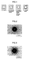
- a dent was formed on the coated surface (30 mm x 30 mm) with a Rockwell hardness tester (C scale), after which the vicinity of the dent was observed under an optical microscope and cracks formed around the dent were estimated according to the criterion shown in Fig. 1. As to this estimation, since the vicinity of the dent is protuberant, cracking is caused as shown in Fig. 1 when the resistance to cracking of the coating layer is low.
- a ball-on-disc frictional wear tester manufactured by CSM Instruments was used. Using a ball of pure aluminum as a partner material, the coefficient of friction of each test piece was measured on a disc surface with a diameter of 20 mm as coated surface under the following conditions: turning radius 3 mm, peripheral speed 150 mm/s, load 2 N, friction distance 100 m, test temperature 500°C, and no lubrication. For the evaluation, values of the coefficient of friction during the test were input into an attached personal computer and the average of these values was calculated. The average values thus obtained were compared.
- Table 1 shows the details of the coating layers of each test piece and the results of the evaluations.
- the definition of their outermost layer, layer just above the base material and intermediate layer is difficult.
- These layers are shown as in Table 1 for facilitating the understanding of comparison with the present invention.
- the results of evaluating their resistance to waste by melting were equal to those obtained for the present inventive test pieces, in the case of all of the samples obtained by using a coating layer composed of a CrN or TiN type material as base, as an outermost layer or a layer just above the base material, such as comparative test pieces Nos. 11, 12, 13, 14 and 15 and conventional test pieces Nos. 21 and 22.
- a coating layer composed of a CrN or TiN type material as base, as an outermost layer or a layer just above the base material, such as comparative test pieces Nos. 11, 12, 13, 14 and 15 and conventional test pieces Nos. 21 and 22.
- the rate of waste by melting was increased, namely, the resistance to waste by melting was low.
- the coating layer was cracked in comparative test pieces Nos. 11, 12 and 13 because their outermost layer did not follow the specifications imposed in the present invention, and the coating layer was cracked in comparative test pieces Nos. 15 and 16 because their layer just above the base material did not follow the specifications imposed in the present invention. Thus, the resistance to cracking was lower than that attained by the present invention.
- Fig. 2, Fig. 3 and Fig. 4 are diagrams showing the results of evaluating the resistance to cracking (the state of the vicinity of a dent formed in Rockwell hardness test) of present inventive test piece No. 5, comparative test piece No. 12 and conventional test piece No. 23, respectively.
- No cracking is observed in the present inventive test piece shown in Fig. 2 (rating A).
- Cracking is observed around the dent in the comparative test piece shown in Fig. 3 (rating C) and the conventional test piece shown in Fig. 4 (rating D).
- core pins for die casting having a surface coating layer structure equal to those of present inventive test pieces Nos. 2, 3 and 5 and conventional test piece No. 22, respectively were produced and then evaluated with respect to their life in an actual mold.
- a toughness-improved material composed of high-speed steel as base and having the chemical composition shown in Table 2 was roughly processed in an annealed state into a shape similar to that of a core pin, and subjected to oil quenching at 1080°C and then thermal refining to 55 HRC by tempering at 600°C. Thereafter, finish processing was conducted and coating treatment was carried out under the same conditions as in Example 1 for obtaining each of the core pins described above. No surface hardening treatment was carried out before the coating treatment.
- the core pins produced above had the shape shown in Fig. 5. Casting was conducted with a die casting machine of 300 t by using an aluminum alloy AC4C at a melt temperature of 700°C. Table 3 shows the life of the various core pins.
- the core pins obtained according to the present invention improved the life of a mold by a factor of three or more as compared with the conventional core pin. Finally, the life of the core pins obtained according to the present invention expired owing to the occurrence of seizure. On the other hand, the conventional core pin early underwent seizure at its pointed end and then its life expired owing to breaking. It was confirmed that as described above, the application of the present invention to a core pin for die casting greatly improves the life of the pin.
- the present invention relates to a casting member used in contact with a molten metal, such as a mold used for die casting or casting, a core pin, a piston ring used in an injection machine, or the like.
- a molten metal such as a mold used for die casting or casting, a core pin, a piston ring used in an injection machine, or the like.
- the molten metal is not limited to aluminum and aluminum alloys, and the casting member can be used also for casting a magnesium alloy.
- the coating layer of the casting member is excellent in resistance to seizure with nonferrous metals
- the present invention can be applied to molds or tools for forging, for example, aluminum, magnesium and their alloys.
Landscapes
- Chemical & Material Sciences (AREA)
- Engineering & Computer Science (AREA)
- Materials Engineering (AREA)
- Mechanical Engineering (AREA)
- Chemical Kinetics & Catalysis (AREA)
- Metallurgy (AREA)
- Organic Chemistry (AREA)
- Inorganic Chemistry (AREA)
- Physical Vapour Deposition (AREA)
- Other Surface Treatments For Metallic Materials (AREA)
- Molds, Cores, And Manufacturing Methods Thereof (AREA)
- Mold Materials And Core Materials (AREA)
Abstract
Description
- The present invention relates to a casting member used in contact with a molten metal, such as a mold used for die casting or casting, a core pin, a piston ring used in an injection machine, or the like.
- Steels such as hot-die steel, high-speed steel, stainless steel and the like have been used in casting members used for molding by casting of a molten metal. A metal to be molded that is most frequently used for molding by casting is an aluminum alloy. In the case of the above-mentioned steel materials used in casting members such as molds, the steel material in a portion of the casting member in contact with the aluminum alloy is wasted by melting in a melt of the aluminum alloy to increase the iron content of the aluminum alloy melt and deteriorate the quality of a cast product. Moreover, the waste by melting of the molds and the like causes various operational troubles.
- As a measure against the above problem, nitriding on the working plane of a casting member has been often conducted because it gives a deep hardened layer and can be conducted at a very low cost. However, since employment of a high-melting aluminum alloy as a material to be molded has become frequent for the purpose of increasing the strength of a cast product, nitriding has the following disadvantages: N in the hardened layer is easily diffused into an aluminum melt at a high temperature, so that the resistance to the waste by melting is deteriorated by the disappearance of the hardened layer, resulting in rapid progress of the waste-by-melting phenomenon.
- In order to solve such a problem, employment of a mold having a working plane coated with a ceramic hardly reactive with a molten metal by physical vapor deposition (hereinafter referred to also as PVD method) has become frequent. There have been proposed, for example, a method in which a base material for mold is subjected to carburizing or nitriding and then a coating layer of TiC, TiN or the like is formed by PVD method (JP-A-61-033734), and a method in which the surface of a mold is coated with a Ti intermediate layer and then TiAlN (JP-A-07-112266). There have also been proposed methods in which CrN is used as a coating layer (JP-A-10-137915 and JP-A-2001-11599).
- The use environment of a member used in contact with a melt, such as a casting mold has become very severe because of a recent increased speed of casting cycle and a recent reduced thickness of a mold due to near net shape. That is, the following troubles have come to be remarkably caused: the thermal expansion of a mold or other members by a molten metal during casting; and the deflection of the mold or the members by shrinkage thereof by application of a mold release agent after the solidification of a material to be processed or by the solidification and shrinkage of the material to be processed. As a result, in the coating layers having the compositions proposed in the prior art references 1 to 4, fine cracks are formed during use of a member having the coating layer, and a molten metal infiltrates into the member through cracks and reacts with iron in a base material just under the surface treatment layer of the member to form an alloy. When a portion just under the surface coating layer is expanded by the formation of the alloy, the following phenomenon is observed: the treatment layer is peeled, so that the waste of the member by melting proceeds rapidly.
- In addition, the above-mentioned coating layers proposed have no sufficient resistance to seizure to cope with use environment that has become severe in recent years. Therefore, when an explanation is made by taking the case of a mold, seizure occurs between the working plane of the mold and a cast product at the time of release of the cast product from the mold in the early stages of use of the mold, resulting in mold correction cycles, a decrease of the life of the mold and the unsatisfactory shape of the cast product.
- The present invention is intended to provide a casting member that is used with its working plane contacted with a high-temperature molten metal, such as a die-casting mold or a core pin, said casting member being free from the problems described above.
- The present inventors noted the mechanism of occurrence of troubles in a casting member used for the purpose described above, and conducted detailed investigation on the influences of the composition, layer structure and forming conditions of a coating layer used on the working plane (the surface to be brought into contact with a melt) of the aforesaid member on the resistance to waste by melting and the resistance to seizure. In addition, the resistance to cracking of the coating layer was investigated in detail for suppressing cracking caused by the deflection of the member.
- As a result, it was found that very satisfactory resistance to waste by melting, resistance to seizure and resistance to cracking can be imparted to the casting member by forming a coating layer comprising at least one nitride, oxinitride or carnonitride composed mainly of V, as an outermost layer, and a coating layer comprising at least one nitride, oxinitride or carnonitride composed mainly of Cr, just above a base material. By this result, it was confirmed that for example, a core pin for die casting of an aluminum alloy is markedly improved in life as a casting member because there are sufficiently suppressed local seizure in the early stages of casting and cracking of the coating layers by the deflection of the pin caused at the time of the solidification and shrinkage of a cast product.
- That is, a first aspect of the present invention is directed to a casting member comprising hot-die steel or high-speed steel as base material and having coating layers at least on its working plane, wherein the outermost layer among the coating layers comprises at least one nitride, oxinitride or carnonitride composed mainly of V, and another coating layer comprising at least one nitride, oxinitride or carnonitride composed mainly of Cr is formed as a layer just above the base material.
- The boundary surface between the above-mentioned outermost layer and layer just above the base material is preferably coated with an intermediate layer comprising at least one nitride, oxinitride or carnonitride composed mainly of V and Cr.
- The thickness of the aforesaid outermost layer is 0.5 to 5.0 µm, and the thickness of the layer just above the base material is preferably 0.5 to 3.0 µm. When the aforesaid intermediate layer is formed, its thickness is preferably 1.0 µm or less.
- In addition, each of the above-mentioned coating layers is preferably formed by physical vapor deposition. Furthermore, the hardness of the coated base material at a depth of 25 µm from the outermost surface of the base material is preferably higher than that at a depth of 500 µm from the outermost surface of the base material by 100 HV 0.2 or more.
- Conventional casting members coated with TiN, TiCN or CrN have become unable to have a sufficient life to cope with use environment that has become severe in recent years. By using a casting member having the surface coating layer structure according to the present invention, the resistance to seizure, resistance to cracking and resistance to waste by melting of a mold can be improved, so that the life of the mold can be greatly improved.
-
- Fig. 1 is a diagram showing a criterion for estimating the degree of cracking in a test for evaluating resistance to cracking by the use of a Rockwell hardness tester.
- Fig. 2 is a photomicrograph showing the result of a test for evaluating the resistance to cracking of present inventive test piece No. 5 (the state of the vicinity of a Rockwell dent).
- Fig. 3 is a photomicrograph showing the result of a test for evaluating the resistance to cracking of comparative test piece No. 12 (the state of the vicinity of a Rockwell dent).
- Fig. 4 is a photomicrograph showing the result of a test for evaluating the resistance to cracking of conventional test piece No. 23 (the state of the vicinity of a Rockwell dent).
- Fig. 5 is a diagram showing the shape of the core pin used in Example 2.
- It is not sufficient that a hard coating film to be formed on the working plane of a casting member is investigated by noting its characteristics only for a melt to be brought into contact with the coating film. That is, total characteristics of the coating film have to be investigated by, of course, considering its affinity for the base material. Therefore, as the coating film in the present invention, a composite coating layer is used which can be given as much as possible both characteristics required of the outermost surface to be brought into contact with the melt and required characteristics for the base material. The main role of the outermost layer used in the present invention is to impart resistance to waste by melting, resistance to seizure and resistance to cracking to a casting member. Thus, the presence of the outermost layer is very important. Accordingly, the coating film in the present invention has to have the above characteristics to a high degree with good balance.
- By the result of investigation by the present inventors, the following was confirmed: as compared with Ti or Cr nitrides, oxinitride nitrides and carnonitrides, nitrides, oxinitride nitrides and carnonitrides, which are composed mainly of V, impart substantially equal resistance to waste by melting but impart higher resistance to seizure in a temperature range (300 to 600°C) for using a member such as a mold in die casting of an aluminum alloy or the like. This is because the nitrides, oxinitride nitrides and carnonitrides, which are composed mainly of V, are properly oxidized in the above temperature range, so that the resulting thin oxide layer deteriorates the affinity for a melt. As a result, seizure with a cast product is suppressed. In other words, since all coating layers of any of TiN, TiAlN and CrN, which have heretofore been proposed, are excellent in oxidation resistance, a relatively active surface is retained also during use, so that seizure with a cast product tends to occur.
- In addition, the following could be confirmed: the nitrides, oxinitrides and carnonitrides, which are composed mainly of V, have a higher toughness than do the Ti or Cr nitrides, oxinitrides and carnonitrides, namely, they have a composition that permits sufficient suppression of cracking of a coating layer caused by the deflection of a member in use. For the reasons described above, the outermost layer among the coating layers formed on the working plane of the casting member of the present invention comprises at least one nitride, oxinitride or carnonitride composed mainly of V. As to the main constituent V, the proportion of V is preferably 70 (atomic %) or more, more preferably 90 (atomic %) or more (inclusive of substantially 100 (atomic %)), based on the total number of metal (semi-metal) atoms excluding nitrogen, oxygen and carbon atoms.
- Next, in the casting member of the present invention, the coating layer formed just above the base material for the casting member (the layer just above the base material) comprises at least one nitride, oxinitride or carnonitride composed mainly of Cr. The nitride, oxinitride or carnonitride composed mainly of Cr gives a coating layer having a low residual compressive stress, an excellent adhesion to the base material and an excellent oxidation resistance. If the adhesion of the layer just above the base material is low, the coating layer is peeled before exhibiting its function.
- In the case of the coating film according to the present invention composed of a composite coating layer, if the oxidation resistance of the layer just above the base material, which constitutes the substrate side of the coating film, is low, the low oxidation resistance becomes a cause for peeling of the coating film irrespective of characteristics the outermost layer. For example, when the composite coating layer according to the present invention is formed of substantially two layers, i.e., the above-mentioned outermost layer and the layer just above the base material, the following trouble is caused if the oxidation resistance of the layer just above the base material is lower than that of the outermost layer: oxidation proceeds on the boundary surface between the outermost layer and the layer just above the base material during use, so that the coating film is peeled to be lost before the exhibition of the function of the outermost layer. Therefore, in view of the adhesion and oxidation resistance of the coating layer, the layer just above the base material comprises at least one nitride, oxinitride or carnonitride composed mainly of Cr. In this case, as to the main constituent Cr, the proportion of Cr is preferably 50 (atomic %) or more, more preferably 90 (atomic %) or more (inclusive of substantially 100 (atomic %)), based on the total number of only metal or semi-metal atoms as above.
- Although the composite coating layer according to the present invention need not satisfy particular conditions concerning the presence of an intermediate layer between the outermost layer and the layer just above the base material, an intermediate layer capable of reconciling the difference in characteristics between the outermost layer and the layer just above the base material is preferably formed also for taking advantage of excellent characteristics of each of these layers. For example, when the composite coating layer according to the present invention is formed of two layers, i.e., the outermost layer and the layer just above the base material, an intermediate layer comprising at least one nitride, oxinitride or carnonitride composed mainly of V and Cr is preferably present on the boundary surface between the outermost layer and the layer just above the base material. Since the outermost layer and the layer just above the base material are different in composition, cracking by the difference in thermal expansion between these two coating layers is expected to occur on the boundary surface between them in a use environment accompanied by a remarkable thermal impulse or quenching. Therefore, an intermediate layer comprising at least one nitride, oxinitride or carnonitride composed mainly of V and Cr is preferably present on the boundary surface between the outermost layer and the layer just above the base material for the purpose of reconciling the difference in characteristics between these two coating layers.
- Next, the thickness of each of the layers constituting the coating layer used in the present invention is described below. The thickness of the outermost layer used in the present invention is preferably 0.5 to 5.0 µm. When the thickness is less than 0.5 µm, no sufficient effect on the resistance to waste by melting, the resistance to seizure and the resistance to cracking cannot be obtained and the outermost layer is early lost particularly by waste by melting. On the other hand, when the outermost layer is formed in a thickness of more than 5.0 µm, it is early peeled in some cases, depending on use conditions. Therefore, the thickness of the outermost layer among coating layers present on the working plane in the present invention is preferably 0.5 to 5.0 µm.
- The thickness of the layer just above the base material used in the present invention is preferably 0.5 to 3.0 µm. When the thickness is less than 0.5 µm, this layer is too thin, so that its sufficient adhesion to the base material is difficult to attain. On the other hand, when this layer is formed in a thickness of more than 3.0 µm, the adhesion- improving effect is not enhanced and cracking by the deflection of the member, or the like is undesirably liable to occur from the layer just above the base material. Therefore, the thickness of the layer just above the base material used in the present invention is preferably 0.5 to 3.0 µm.
- When the above-mentioned intermediate layer is formed, the thickness of the intermediate layer is preferably 1.00 µm or less. This is because even if the intermediate layer is formed in a thickness of more than 1.00 µm, no remarkable effect of the formation can be obtained. However, when the thickness is too small, the difference in characteristics between the outermost layer and the layer just above the base material cannot be reconciled. Therefore, the thickness of the intermediate layer used in the present invention is preferably 0.05 µm or more. The thickness is more preferably 0.10 to 0.50 µm.
- Next, the composition of each of the layers constituting the coating layer used in the present invention is concretely described below. For example, as the composition of the nitride that constitutes the outermost layer used in the present invention, there may be exemplified compositions such as VN, VTiN, VCrN, VBN and the like, which are composed mainly of V. Similarly, as the composition of the nitride that constitutes the layer just above the base material, there may be exemplified compositions relatively excellent in oxidation resistance and heat resistance, such as CrN, CrTiN, CrAlN, CrSiN, CrBN and the like, which are composed mainly of Cr. When the shape of the working plane of a member such as a mold is so complicated that a stress is very liable to be centered at convexities, a coating film of VN, VTiN or the like among the above-exemplified nitrides, which has a relatively low residual stress and an excellent adhesion, is preferably used as the outermost layer. When a coating film having oxidation resistance is required because of a high casting temperature, a coating film of VCrN or the like is preferable.
- Although the above description is given by taking the case of the nitrides, the same effect as above can be obtained also by the use of the oxinitrides or the carnonitrides. In addition, although the outermost layer and the layer just above the base material are composed mainly of V and Cr, respectively, a metal element of group IVa, Va or VIa and A1, Si, B or the like may be added to the outermost layer in a proportion of 30 atomic % or less, more preferably 10 atomic % or less and may be added to the layer just above the base material in a proportion of 50 atomic % or less, more preferably a small proportion of 10 atomic % or less. Furthermore, two or more nitrides, oxinitrides or carnonitrides, which are different in composition, may be used in the form of a multi-layer film.
- A coating method for forming the coating layer of the casting member of the present invention is not particularly limited. Considering thermal influence on the base material to be coated, the fatigue strength of tools, the adhesion of the coating film, and the like, it is preferable to adopt physical vapor deposition in which a bias voltage is applied to the base material to be coated, such as an arc ion plating method or a sputtering method, in which film formation is possible at a temperature lower than a tempering temperature for hot-die steel or high-speed steel as the base material to be coated, and a compressive stress remains in the coating film.
- Furthermore, in the case of the base material to be coated which is used in the present invention, its hardness at a depth of 25 µm from the outermost surface of the base material is preferably higher than that at a depth of 500 µm from the outermost surface of the base material by 100 HV 0.2 or more in terms of Vickers hardness defined in JIS-Z-2244, for the purpose of further improving the wear resistance. That is, it is preferable to carry out previously a surface hardening treatment utilizing diffusion, such as nitriding or carburizing, as a specific example of treatment for achieving the above purpose. In this case, a compound layer such as a nitride layer called a white layer, which is formed by nitriding, or a carbide layer observed in the case of carburizing becomes a cause for the deterioration of the adhesion of the layer just above the base material, and hence is preferably inhibited from forming by controlling the treatment conditions or removed by polishing or the like.
- The present invention is illustrated in detail with reference to the following examples, which should not be construed as limiting the scope of the invention. Changes may be properly made without departing from the gist of the invention and all of them are included in the technical scope of the invention.
- SKD 61 specified in JIS was prepared, and subjected to oil quenching from 1030°C and then thermal refining to 47 HRC by tempering at 550 to 630°C. Thereafter, the thus treated material was processed into the following test pieces: columnar test pieces with a diameter of 10 mm and a length of 100 mm for evaluating the resistance to waste by melting, plate-shaped test pieces with a thickness of 3 mm and a length of each side of 30 mm for evaluating the resistance to cracking, and discoid test pieces with a diameter of 20 mm and a thickness of 5 mm for evaluating the resistance to seizure. As base materials, the test pieces described above were subjected to coating treatment. Among the test pieces, test pieces to be subjected to surface hardening treatment before the coating treatment were subjected to ion nitriding treatment under the following conditions.
- As the surface hardening treatment before the coating treatment, the ion nitriding treatment was carried out by maintaining the test pieces at 500°C for 10 hours in an atmosphere of N2 in a flow percentage of 5% (balance: H2). Then, the test surface of each test piece was finished by polishing. By the fact that the hardness at a depth of 25 µm from the surface after the finishing was 680 HV 0.2 in all the test pieces subjected to the nitriding treatment, it was confirmed that the hardness at a depth of 25 µm was higher than the hardness at a depth of 500 µm of 47 HRC (= 471 HV 0.2) by 100 HV 0.2. The surfaces of the base materials after the finishing were subjected to the coating treatment under the following conditions together with the surfaces of the other test pieces.
- The coating was conducted with an arc ion plating apparatus as follows. A bias voltage of -400 V was applied to each base material to be coated, in an Ar atmosphere (pressure: 0.5 Pa) and plasma cleaning with a hot filament was conducted for 60 minutes.
Then, using various metal targets as sources for vapors of metal components and a reaction gas composed of N2 gas as base and optionally CH4 gas and N2 + O2 mixed gas, a film was formed at a temperature of the base material to be coated of 500°C, a reaction gas pressure of 3.0 Pa and a bias voltage of -50 V so that the total thickness of all layers might be about 5 µm. An intermediate layer was formed by operating targets for forming a layer just above the base material and targets for forming an outermost layer, at the same time. - For the test pieces thus obtained, the resistance to waste by melting, resistance to cracking and resistance to seizure of the coated surface of each test piece were evaluated. Evaluation test conditions for each of these resistances are described below.
- Each test piece was immersed in a melt of an aluminum alloy AC4C at 750°C for 3 hours, and the resistance to waste by melting was evaluated in terms of the ratio between the mass values of the test piece before and after the test.
- A dent was formed on the coated surface (30 mm x 30 mm) with a Rockwell hardness tester (C scale), after which the vicinity of the dent was observed under an optical microscope and cracks formed around the dent were estimated according to the criterion shown in Fig. 1. As to this estimation, since the vicinity of the dent is protuberant, cracking is caused as shown in Fig. 1 when the resistance to cracking of the coating layer is low.
- For evaluating the resistance to seizure, a ball-on-disc frictional wear tester manufactured by CSM Instruments was used. Using a ball of pure aluminum as a partner material, the coefficient of friction of each test piece was measured on a disc surface with a diameter of 20 mm as coated surface under the following conditions: turning radius 3 mm, peripheral speed 150 mm/s, load 2 N, friction distance 100 m, test temperature 500°C, and no lubrication. For the evaluation, values of the coefficient of friction during the test were input into an attached personal computer and the average of these values was calculated. The average values thus obtained were compared.
- Table 1 shows the details of the coating layers of each test piece and the results of the evaluations. In the case of comparative test pieces and conventional test pieces, which did not have the coating layer structure used in the present invention, the definition of their outermost layer, layer just above the base material and intermediate layer is difficult. These layers are shown as in Table 1 for facilitating the understanding of comparison with the present invention. Before and after the coating treatment, there was no change in the above-mentioned hardness values of the base material adjusted by the surface hardening treatment before the coating treatment.


- It can be seen that as shown in Table 1, all of the present inventive test pieces are very excellent in resistance to waste by melting, resistance to cracking and resistance to seizure because their coating layer structure was within the range specified in the present invention.
- On the other hand, as to the evaluation results for the comparative test pieces and the conventional test pieces, the results of evaluating their resistance to waste by melting were equal to those obtained for the present inventive test pieces, in the case of all of the samples obtained by using a coating layer composed of a CrN or TiN type material as base, as an outermost layer or a layer just above the base material, such as comparative test pieces Nos. 11, 12, 13, 14 and 15 and conventional test pieces Nos. 21 and 22. However, in the case of comparative test piece No. 16 and conventional test piece No. 23, which were obtained by using a coating layer of a TiAlN type material as a layer just above the base material, the rate of waste by melting was increased, namely, the resistance to waste by melting was low. The reason is conjectured as follows: since the above-mentioned coating layer composed of a CrN or TiN type material as base was relatively good in adhesion, it was not peeled by thermal impulse or the difference in thermal expansion between the coating layer and the base material when the test piece was immersed in the melt of the aluminum alloy.
- In the case of comparative test pieces Nos. 11, 12, 13 and 14 having an outermost layer not following the specifications imposed in the present invention and conventional test pieces Nos. 21, 22 and 23 having a fundamental coating structure different from that used in the present invention, the coefficient of friction with aluminum was increased, resulting in a low resistance to seizure. Particularly in the case of comparative test pieces Nos. 13 and 14 having a coating layer of a CrN or TiAlN type material as an outermost layer and conventional test pieces Nos. 22 and 23, aluminum as partner material underwent seizure during the friction test, so that the test was discontinued.
- As to the resistance to cracking of the coating layer, the coating layer was cracked in comparative test pieces Nos. 11, 12 and 13 because their outermost layer did not follow the specifications imposed in the present invention, and the coating layer was cracked in comparative test pieces Nos. 15 and 16 because their layer just above the base material did not follow the specifications imposed in the present invention. Thus, the resistance to cracking was lower than that attained by the present invention.
- Fig. 2, Fig. 3 and Fig. 4 are diagrams showing the results of evaluating the resistance to cracking (the state of the vicinity of a dent formed in Rockwell hardness test) of present inventive test piece No. 5, comparative test piece No. 12 and conventional test piece No. 23, respectively. No cracking is observed in the present inventive test piece shown in Fig. 2 (rating A). Cracking is observed around the dent in the comparative test piece shown in Fig. 3 (rating C) and the conventional test piece shown in Fig. 4 (rating D).
- Next, core pins for die casting having a surface coating layer structure equal to those of present inventive test pieces Nos. 2, 3 and 5 and conventional test piece No. 22, respectively were produced and then evaluated with respect to their life in an actual mold.
- First, a toughness-improved material composed of high-speed steel as base and having the chemical composition shown in Table 2 was roughly processed in an annealed state into a shape similar to that of a core pin, and subjected to oil quenching at 1080°C and then thermal refining to 55 HRC by tempering at 600°C. Thereafter, finish processing was conducted and coating treatment was carried out under the same conditions as in Example 1 for obtaining each of the core pins described above. No surface hardening treatment was carried out before the coating treatment. In each of the core pins thus obtained, both of its hardness values at depths of 25 µm and 500 µm from the outermost surface of its base material were maintained at the above-mentioned thermal refining hardness 55 HRC (= 595 HV 0.2) before and after the coating treatment.

- The core pins produced above had the shape shown in Fig. 5. Casting was conducted with a die casting machine of 300 t by using an aluminum alloy AC4C at a melt temperature of 700°C. Table 3 shows the life of the various core pins.

- The core pins obtained according to the present invention improved the life of a mold by a factor of three or more as compared with the conventional core pin. Finally, the life of the core pins obtained according to the present invention expired owing to the occurrence of seizure. On the other hand, the conventional core pin early underwent seizure at its pointed end and then its life expired owing to breaking. It was confirmed that as described above, the application of the present invention to a core pin for die casting greatly improves the life of the pin.
- The present invention relates to a casting member used in contact with a molten metal, such as a mold used for die casting or casting, a core pin, a piston ring used in an injection machine, or the like. The molten metal (a casting material) is not limited to aluminum and aluminum alloys, and the casting member can be used also for casting a magnesium alloy. Considering, for example, that the coating layer of the casting member is excellent in resistance to seizure with nonferrous metals, the present invention can be applied to molds or tools for forging, for example, aluminum, magnesium and their alloys.
Claims (6)
- A member used for casting comprising hot-die steel or high-speed steel as base material and having coating layers at least on its working plane, wherein the outermost layer among the coating layers consisting essentially of at least one of nitride, oxinitride or carnonitride composed mainly of V, and another coating layer comprising at least one of nitride, oxinitride or carnonitride composed mainly of Cr is formed as a layer just above the base material.
- A member used for casting according to claim 1, wherein the thickness of said outermost layer is 0.5 to 5.0 µm, and the thickness of said layer just above the base material is 0.5 to 3.0 µm.
- A member used for casting according to claim 1 or 2, wherein an intermediate layer consisting essentially of at least one of nitride, oxinitride or carnonitride composed mainly of V and Cr is present on the boundary between said outermost layer and said layer just above the base material.
- A member used for casting according to claim 3, wherein the thickness of said intermediate layer is 1.00 µm or less.
- A member used for casting according to any of claims 1-4, wherein each of the coating layers is formed by physical vapor deposition.
- A member used for casting according to any of claims 1-5, wherein the hardness of the base material at a depth of 25 µm from the outermost surface for being coated is higher than that at a depth of 500 µm from the outermost surface for being coated by 100 HV 0.2 or more.
Applications Claiming Priority (1)
| Application Number | Priority Date | Filing Date | Title |
|---|---|---|---|
| JP2004233035A JP4513058B2 (en) | 2004-08-10 | 2004-08-10 | Casting parts |
Publications (2)
| Publication Number | Publication Date |
|---|---|
| EP1626104A1 true EP1626104A1 (en) | 2006-02-15 |
| EP1626104B1 EP1626104B1 (en) | 2007-08-29 |
Family
ID=35169840
Family Applications (1)
| Application Number | Title | Priority Date | Filing Date |
|---|---|---|---|
| EP05015897A Expired - Lifetime EP1626104B1 (en) | 2004-08-10 | 2005-07-21 | Member with coating layers used for casting |
Country Status (6)
| Country | Link |
|---|---|
| US (1) | US7159640B2 (en) |
| EP (1) | EP1626104B1 (en) |
| JP (1) | JP4513058B2 (en) |
| CN (1) | CN100335674C (en) |
| AT (1) | ATE371754T1 (en) |
| DE (1) | DE602005002203T2 (en) |
Cited By (2)
| Publication number | Priority date | Publication date | Assignee | Title |
|---|---|---|---|---|
| EP1918421A1 (en) * | 2006-09-27 | 2008-05-07 | Hitachi Metals, Limited | Hard-material-coated member excellent in durability |
| EP3372706A4 (en) * | 2015-11-05 | 2019-07-03 | Fujita Giken Co., Ltd. | Coating member, surface coated mold, and film formation method |
Families Citing this family (25)
| Publication number | Priority date | Publication date | Assignee | Title |
|---|---|---|---|---|
| JP4495568B2 (en) * | 2004-11-01 | 2010-07-07 | 株式会社神戸製鋼所 | Hard coating |
| JP4883400B2 (en) * | 2006-09-27 | 2012-02-22 | 日立金属株式会社 | Casting parts |
| JP2008188609A (en) * | 2007-02-02 | 2008-08-21 | Daido Steel Co Ltd | Die casting mold and surface treatment method thereof |
| JP2008188735A (en) * | 2007-02-06 | 2008-08-21 | Mitsubishi Materials Corp | Surface coated cutting tool with excellent chipping resistance due to hard coating layer in heavy cutting of difficult-to-cut materials |
| DE102007027245B4 (en) * | 2007-06-13 | 2018-08-30 | Federal-Mogul Burscheid Gmbh | piston ring |
| JP2009068047A (en) | 2007-09-11 | 2009-04-02 | Kobe Steel Ltd | Hard coating film, material coated with hard coating film and die for cold plastic working |
| JP2009101385A (en) * | 2007-10-23 | 2009-05-14 | Daido Steel Co Ltd | Die casting mold and manufacturing method thereof |
| US8956722B2 (en) * | 2009-02-27 | 2015-02-17 | Oerlikon Metaplas Gmbh | Layer system for the formation of a surface layer on a surface of a substrate and coating method for the manufacture of a layer system |
| TWI503431B (en) * | 2010-12-24 | 2015-10-11 | Hon Hai Prec Ind Co Ltd | Articles and method for making the same |
| TWI471450B (en) * | 2010-12-29 | 2015-02-01 | Hon Hai Prec Ind Co Ltd | Coated article and method for making the same |
| BRPI1103935A2 (en) * | 2011-08-17 | 2013-08-06 | Mahle Metal Leve Sa | piston ring |
| CN103826773B (en) * | 2011-09-28 | 2016-04-27 | 日立金属株式会社 | Coated member with excellent sliding properties |
| CN102744392A (en) * | 2012-07-04 | 2012-10-24 | 江苏理士电池有限公司 | Processing method for cast-weld mould of lead-acid storage battery |
| KR20140019947A (en) * | 2012-08-07 | 2014-02-18 | 현대자동차주식회사 | Coating material for aluminum die casting and the method for manufacturing thereof |
| JP5995029B2 (en) * | 2013-03-28 | 2016-09-28 | オーエスジー株式会社 | Hard coating for tool, manufacturing method thereof, and hard coating coated metal working tool |
| WO2014155633A1 (en) * | 2013-03-28 | 2014-10-02 | オーエスジー株式会社 | Hard film for machining tools and hard film-coated metal machining tool |
| US10030773B2 (en) | 2016-03-04 | 2018-07-24 | Mahle International Gmbh | Piston ring |
| DE102016221575A1 (en) * | 2016-11-03 | 2018-05-03 | Volkswagen Aktiengesellschaft | Casting tool with squeezer device for indirect recompression, ceramic squeezer stamp, ceramic squeezerbeverse and method for producing a casting |
| JP7482863B2 (en) * | 2018-11-14 | 2024-05-14 | エリコン・サーフェス・ソリューションズ・アクチェンゲゼルシャフト,プフェフィコーン | Coatings for improved performance and life in plastics processing applications |
| KR102460884B1 (en) * | 2018-12-03 | 2022-10-31 | 히다찌긴조꾸가부시끼가이사 | Cover mold for hot stamping |
| US12331397B2 (en) | 2019-05-29 | 2025-06-17 | Oerlikon Surface Solutions Ag, Pfäffikon | Coated forming tools with enhanced performance and increased service life |
| FR3097791B1 (en) | 2019-06-28 | 2021-06-18 | Safran Aircraft Engines | HOT CONFORMATION CORE OF A METAL PIECE AND MANUFACTURING, REGENERATION AND CONFORMATION PROCESS |
| US20220290289A1 (en) * | 2021-03-10 | 2022-09-15 | Vapor Technologies, Inc. | Pvd coatings for aluminum die casting molds |
| CN116145079A (en) * | 2022-09-30 | 2023-05-23 | 安徽信息工程学院 | A kind of aluminum die-casting mold steel surface coating material and preparation method |
| CN120193232A (en) * | 2025-05-27 | 2025-06-24 | 金迈克(潍坊)新材料科技有限公司 | A process for preparing light gold color by a planar target sputtering coating machine |
Citations (9)
| Publication number | Priority date | Publication date | Assignee | Title |
|---|---|---|---|---|
| JPS6133734A (en) | 1984-07-26 | 1986-02-17 | Toyota Motor Corp | Surface treatment of metallic mold for casting |
| JPH05209261A (en) * | 1991-12-03 | 1993-08-20 | Sumitomo Metal Mining Co Ltd | Articles with corrosion and abrasion resistant coating |
| US5246787A (en) * | 1989-11-22 | 1993-09-21 | Balzers Aktiengesellschaft | Tool or instrument with a wear-resistant hard coating for working or processing organic materials |
| JPH07112266A (en) | 1993-10-15 | 1995-05-02 | Ube Ind Ltd | Die casting mold |
| JPH0813134A (en) * | 1994-06-24 | 1996-01-16 | Sumitomo Metal Mining Co Ltd | Mold for plastic molding and manufacturing method thereof |
| JPH10137915A (en) | 1996-11-01 | 1998-05-26 | Aisin Seiki Co Ltd | Casting mold |
| JP2001011599A (en) | 1999-06-28 | 2001-01-16 | Hiroshima Aluminum Industry Co Ltd | Die casting parts |
| JP2002307129A (en) * | 2001-04-10 | 2002-10-22 | Hitachi Metals Ltd | Coated tool for hot working with excellent lubricant adhesion and wear resistance |
| JP2004202512A (en) * | 2002-12-24 | 2004-07-22 | Toyota Motor Corp | Pressing pin for die casting |
Family Cites Families (7)
| Publication number | Priority date | Publication date | Assignee | Title |
|---|---|---|---|---|
| JPS5152942A (en) * | 1974-11-05 | 1976-05-11 | Toyoda Chuo Kenkyusho Kk | Daigoeezokugenso mataha chitanno tankabutsusoto kuromuno tankabutsusono nijuhifukusoojusuru kobuzai |
| GB2149689B (en) * | 1983-11-12 | 1988-02-17 | Bip Chemicals Ltd | Applying insulating coatings |
| US4892792A (en) * | 1987-10-01 | 1990-01-09 | Gte Laboratories Incorporated | A1N coated silicon nitride based cutting tools |
| JPH07102266A (en) | 1993-11-17 | 1995-04-18 | Tonen Corp | Method for reducing sulfur in petroleum distillates |
| JP2001025856A (en) * | 1999-07-13 | 2001-01-30 | Maizuru:Kk | Manufacturing method of die-cast products and die for die-casting |
| JP3909658B2 (en) * | 2001-06-15 | 2007-04-25 | ユケン工業株式会社 | Vanadium-based coating film forming method and vanadium-based coating-treated inorganic product |
| KR100623012B1 (en) * | 2002-01-29 | 2006-09-13 | 제이에프이 스틸 가부시키가이샤 | Continuous casting mold copper plate and manufacturing method |
-
2004
- 2004-08-10 JP JP2004233035A patent/JP4513058B2/en not_active Expired - Fee Related
-
2005
- 2005-07-21 DE DE602005002203T patent/DE602005002203T2/en not_active Expired - Lifetime
- 2005-07-21 AT AT05015897T patent/ATE371754T1/en active
- 2005-07-21 EP EP05015897A patent/EP1626104B1/en not_active Expired - Lifetime
- 2005-08-08 US US11/198,167 patent/US7159640B2/en not_active Expired - Lifetime
- 2005-08-10 CN CNB2005100914013A patent/CN100335674C/en not_active Expired - Fee Related
Patent Citations (9)
| Publication number | Priority date | Publication date | Assignee | Title |
|---|---|---|---|---|
| JPS6133734A (en) | 1984-07-26 | 1986-02-17 | Toyota Motor Corp | Surface treatment of metallic mold for casting |
| US5246787A (en) * | 1989-11-22 | 1993-09-21 | Balzers Aktiengesellschaft | Tool or instrument with a wear-resistant hard coating for working or processing organic materials |
| JPH05209261A (en) * | 1991-12-03 | 1993-08-20 | Sumitomo Metal Mining Co Ltd | Articles with corrosion and abrasion resistant coating |
| JPH07112266A (en) | 1993-10-15 | 1995-05-02 | Ube Ind Ltd | Die casting mold |
| JPH0813134A (en) * | 1994-06-24 | 1996-01-16 | Sumitomo Metal Mining Co Ltd | Mold for plastic molding and manufacturing method thereof |
| JPH10137915A (en) | 1996-11-01 | 1998-05-26 | Aisin Seiki Co Ltd | Casting mold |
| JP2001011599A (en) | 1999-06-28 | 2001-01-16 | Hiroshima Aluminum Industry Co Ltd | Die casting parts |
| JP2002307129A (en) * | 2001-04-10 | 2002-10-22 | Hitachi Metals Ltd | Coated tool for hot working with excellent lubricant adhesion and wear resistance |
| JP2004202512A (en) * | 2002-12-24 | 2004-07-22 | Toyota Motor Corp | Pressing pin for die casting |
Non-Patent Citations (4)
| Title |
|---|
| PATENT ABSTRACTS OF JAPAN vol. 017, no. 655 (C - 1136) 6 December 1993 (1993-12-06) * |
| PATENT ABSTRACTS OF JAPAN vol. 1996, no. 05 31 May 1996 (1996-05-31) * |
| PATENT ABSTRACTS OF JAPAN vol. 2003, no. 02 5 February 2003 (2003-02-05) * |
| PATENT ABSTRACTS OF JAPAN vol. 2003, no. 12 5 December 2003 (2003-12-05) * |
Cited By (3)
| Publication number | Priority date | Publication date | Assignee | Title |
|---|---|---|---|---|
| EP1918421A1 (en) * | 2006-09-27 | 2008-05-07 | Hitachi Metals, Limited | Hard-material-coated member excellent in durability |
| US7744056B2 (en) | 2006-09-27 | 2010-06-29 | Hitachi Metals, Ltd. | Hard-material-coated member excellent in durability |
| EP3372706A4 (en) * | 2015-11-05 | 2019-07-03 | Fujita Giken Co., Ltd. | Coating member, surface coated mold, and film formation method |
Also Published As
| Publication number | Publication date |
|---|---|
| US20060032602A1 (en) | 2006-02-16 |
| JP4513058B2 (en) | 2010-07-28 |
| EP1626104B1 (en) | 2007-08-29 |
| CN100335674C (en) | 2007-09-05 |
| DE602005002203D1 (en) | 2007-10-11 |
| DE602005002203T2 (en) | 2008-04-10 |
| CN1733393A (en) | 2006-02-15 |
| ATE371754T1 (en) | 2007-09-15 |
| JP2006051510A (en) | 2006-02-23 |
| US7159640B2 (en) | 2007-01-09 |
Similar Documents
| Publication | Publication Date | Title |
|---|---|---|
| EP1626104B1 (en) | Member with coating layers used for casting | |
| US7744056B2 (en) | Hard-material-coated member excellent in durability | |
| JP4656473B2 (en) | Coated tool for hot working with excellent lubricant adhesion and wear resistance | |
| Cooke et al. | Development of duplex nitrided and closed field unbalanced magnetron sputter ion plated CrTiAlN-based coatings for H13 aluminium extrusion dies | |
| CN101152780B (en) | Hard-material-coated member excellent in durability | |
| JP3410303B2 (en) | Fe-Ni-Cr-Al ferrite alloy excellent in molten metal erosion resistance and wear resistance and method for producing the same | |
| JP2002307128A (en) | Coating tool for warm and hot working having excellent seizure resistance and wear resistance | |
| JP3029642B2 (en) | Casting molds or molten metal fittings with excellent erosion resistance to molten metal | |
| JP2004019001A (en) | Hot tool steel and mold members with excellent erosion resistance | |
| JP4883400B2 (en) | Casting parts | |
| WO2019039225A1 (en) | Aluminum die-casting mold part | |
| JP2006075867A (en) | Member for casting | |
| JP7509129B2 (en) | Coated mold, method for manufacturing coated mold, and target for forming hard film | |
| JPS6133734A (en) | Surface treatment of metallic mold for casting | |
| JPH0971856A (en) | Abrasion resistant hard coating material and method for producing the same | |
| Faccoli et al. | Effect of different coatings on thermal fatigue behaviour of AISI H11 hot work tool steel | |
| Sokovic et al. | Improvement of tool life of die-casting tools with duplex treatment | |
| JP4154024B2 (en) | Casting member for Al or Al alloy melts with excellent melt resistance | |
| JP4547656B2 (en) | Coated tool for hot working with excellent lubricant adhesion and wear resistance | |
| JPH08165581A (en) | Die casting material | |
| Gulizia | Soldering in high pressure die casting (HPDC), performance evaluation and characterisation of physical vapour deposition (PVD) coatings | |
| Bandeira Neto et al. | Surface Coatings for Service Life Increase of H13 Steel Permanent Mold Used for Alsi12cu4ni2mg Alloy Casting | |
| Yılmaz et al. | Effect of Controlled Oxygen Incorporation on the Structural, Mechanical, and High-Temperature Tribological Behavior of AlCrON Coatings | |
| JPH10237624A (en) | Casting member excellent in molten Al resistance and method for producing the same | |
| JP2011125911A (en) | Die for cold forging |
Legal Events
| Date | Code | Title | Description |
|---|---|---|---|
| PUAI | Public reference made under article 153(3) epc to a published international application that has entered the european phase |
Free format text: ORIGINAL CODE: 0009012 |
|
| AK | Designated contracting states |
Kind code of ref document: A1 Designated state(s): AT BE BG CH CY CZ DE DK EE ES FI FR GB GR HU IE IS IT LI LT LU LV MC NL PL PT RO SE SI SK TR |
|
| AX | Request for extension of the european patent |
Extension state: AL BA HR MK YU |
|
| 17P | Request for examination filed |
Effective date: 20060331 |
|
| AKX | Designation fees paid |
Designated state(s): AT DE GB |
|
| GRAP | Despatch of communication of intention to grant a patent |
Free format text: ORIGINAL CODE: EPIDOSNIGR1 |
|
| GRAS | Grant fee paid |
Free format text: ORIGINAL CODE: EPIDOSNIGR3 |
|
| GRAA | (expected) grant |
Free format text: ORIGINAL CODE: 0009210 |
|
| AK | Designated contracting states |
Kind code of ref document: B1 Designated state(s): AT DE GB |
|
| REG | Reference to a national code |
Ref country code: GB Ref legal event code: FG4D |
|
| REF | Corresponds to: |
Ref document number: 602005002203 Country of ref document: DE Date of ref document: 20071011 Kind code of ref document: P |
|
| PLBE | No opposition filed within time limit |
Free format text: ORIGINAL CODE: 0009261 |
|
| STAA | Information on the status of an ep patent application or granted ep patent |
Free format text: STATUS: NO OPPOSITION FILED WITHIN TIME LIMIT |
|
| 26N | No opposition filed |
Effective date: 20080530 |
|
| PGFP | Annual fee paid to national office [announced via postgrant information from national office to epo] |
Ref country code: DE Payment date: 20180710 Year of fee payment: 14 |
|
| PGFP | Annual fee paid to national office [announced via postgrant information from national office to epo] |
Ref country code: AT Payment date: 20180625 Year of fee payment: 14 Ref country code: GB Payment date: 20180718 Year of fee payment: 14 |
|
| REG | Reference to a national code |
Ref country code: DE Ref legal event code: R119 Ref document number: 602005002203 Country of ref document: DE |
|
| REG | Reference to a national code |
Ref country code: AT Ref legal event code: MM01 Ref document number: 371754 Country of ref document: AT Kind code of ref document: T Effective date: 20190721 |
|
| GBPC | Gb: european patent ceased through non-payment of renewal fee |
Effective date: 20190721 |
|
| PG25 | Lapsed in a contracting state [announced via postgrant information from national office to epo] |
Ref country code: GB Free format text: LAPSE BECAUSE OF NON-PAYMENT OF DUE FEES Effective date: 20190721 Ref country code: AT Free format text: LAPSE BECAUSE OF NON-PAYMENT OF DUE FEES Effective date: 20190721 Ref country code: DE Free format text: LAPSE BECAUSE OF NON-PAYMENT OF DUE FEES Effective date: 20200201 |