EP1624827B1 - Stents aus einem material geringer bruchdehnung - Google Patents
Stents aus einem material geringer bruchdehnung Download PDFInfo
- Publication number
- EP1624827B1 EP1624827B1 EP04727541A EP04727541A EP1624827B1 EP 1624827 B1 EP1624827 B1 EP 1624827B1 EP 04727541 A EP04727541 A EP 04727541A EP 04727541 A EP04727541 A EP 04727541A EP 1624827 B1 EP1624827 B1 EP 1624827B1
- Authority
- EP
- European Patent Office
- Prior art keywords
- stent
- stent according
- elongation
- zigzagged
- rupture
- Prior art date
- Legal status (The legal status is an assumption and is not a legal conclusion. Google has not performed a legal analysis and makes no representation as to the accuracy of the status listed.)
- Expired - Lifetime
Links
- 239000000463 material Substances 0.000 title claims description 29
- 238000005452 bending Methods 0.000 claims description 37
- 229910001092 metal group alloy Inorganic materials 0.000 claims description 9
- 229910000861 Mg alloy Inorganic materials 0.000 claims description 5
- 229910000640 Fe alloy Inorganic materials 0.000 claims description 4
- 229910001080 W alloy Inorganic materials 0.000 claims description 3
- 238000013461 design Methods 0.000 description 24
- 208000010392 Bone Fractures Diseases 0.000 description 6
- XEEYBQQBJWHFJM-UHFFFAOYSA-N Iron Chemical compound [Fe] XEEYBQQBJWHFJM-UHFFFAOYSA-N 0.000 description 6
- 210000004204 blood vessel Anatomy 0.000 description 5
- 206010000891 acute myocardial infarction Diseases 0.000 description 3
- 238000011161 development Methods 0.000 description 3
- 208000037803 restenosis Diseases 0.000 description 3
- FYYHWMGAXLPEAU-UHFFFAOYSA-N Magnesium Chemical compound [Mg] FYYHWMGAXLPEAU-UHFFFAOYSA-N 0.000 description 2
- PXHVJJICTQNCMI-UHFFFAOYSA-N Nickel Chemical compound [Ni] PXHVJJICTQNCMI-UHFFFAOYSA-N 0.000 description 2
- 208000031481 Pathologic Constriction Diseases 0.000 description 2
- 230000008901 benefit Effects 0.000 description 2
- 208000029078 coronary artery disease Diseases 0.000 description 2
- 238000006731 degradation reaction Methods 0.000 description 2
- 238000002513 implantation Methods 0.000 description 2
- 229910052742 iron Inorganic materials 0.000 description 2
- 230000007774 longterm Effects 0.000 description 2
- 239000011777 magnesium Substances 0.000 description 2
- 229910052751 metal Inorganic materials 0.000 description 2
- 239000002184 metal Substances 0.000 description 2
- 150000002739 metals Chemical class 0.000 description 2
- 238000000034 method Methods 0.000 description 2
- 239000000203 mixture Substances 0.000 description 2
- 238000007634 remodeling Methods 0.000 description 2
- 230000036262 stenosis Effects 0.000 description 2
- 208000037804 stenosis Diseases 0.000 description 2
- 230000001732 thrombotic effect Effects 0.000 description 2
- WFKWXMTUELFFGS-UHFFFAOYSA-N tungsten Chemical compound [W] WFKWXMTUELFFGS-UHFFFAOYSA-N 0.000 description 2
- 239000010937 tungsten Substances 0.000 description 2
- 229910052720 vanadium Inorganic materials 0.000 description 2
- KKJUPNGICOCCDW-UHFFFAOYSA-N 7-N,N-Dimethylamino-1,2,3,4,5-pentathiocyclooctane Chemical compound CN(C)C1CSSSSSC1 KKJUPNGICOCCDW-UHFFFAOYSA-N 0.000 description 1
- 206010002383 Angina Pectoris Diseases 0.000 description 1
- 206010003210 Arteriosclerosis Diseases 0.000 description 1
- 208000037260 Atherosclerotic Plaque Diseases 0.000 description 1
- VYZAMTAEIAYCRO-UHFFFAOYSA-N Chromium Chemical compound [Cr] VYZAMTAEIAYCRO-UHFFFAOYSA-N 0.000 description 1
- 206010061216 Infarction Diseases 0.000 description 1
- WHXSMMKQMYFTQS-UHFFFAOYSA-N Lithium Chemical compound [Li] WHXSMMKQMYFTQS-UHFFFAOYSA-N 0.000 description 1
- 208000007718 Stable Angina Diseases 0.000 description 1
- 229910000831 Steel Inorganic materials 0.000 description 1
- 208000007536 Thrombosis Diseases 0.000 description 1
- 206010053648 Vascular occlusion Diseases 0.000 description 1
- 208000033774 Ventricular Remodeling Diseases 0.000 description 1
- 238000002399 angioplasty Methods 0.000 description 1
- 238000013459 approach Methods 0.000 description 1
- 210000001367 artery Anatomy 0.000 description 1
- 238000006065 biodegradation reaction Methods 0.000 description 1
- 230000015556 catabolic process Effects 0.000 description 1
- 230000010261 cell growth Effects 0.000 description 1
- 230000008859 change Effects 0.000 description 1
- 238000006243 chemical reaction Methods 0.000 description 1
- 229910052804 chromium Inorganic materials 0.000 description 1
- 239000011651 chromium Substances 0.000 description 1
- 239000000470 constituent Substances 0.000 description 1
- 210000004351 coronary vessel Anatomy 0.000 description 1
- 230000006378 damage Effects 0.000 description 1
- 230000007423 decrease Effects 0.000 description 1
- 230000003247 decreasing effect Effects 0.000 description 1
- 230000006866 deterioration Effects 0.000 description 1
- 238000006073 displacement reaction Methods 0.000 description 1
- 238000004090 dissolution Methods 0.000 description 1
- 230000002526 effect on cardiovascular system Effects 0.000 description 1
- 230000000694 effects Effects 0.000 description 1
- 230000002255 enzymatic effect Effects 0.000 description 1
- 230000002349 favourable effect Effects 0.000 description 1
- 230000012010 growth Effects 0.000 description 1
- 208000037824 growth disorder Diseases 0.000 description 1
- 230000035876 healing Effects 0.000 description 1
- 230000003301 hydrolyzing effect Effects 0.000 description 1
- 239000007943 implant Substances 0.000 description 1
- 230000007574 infarction Effects 0.000 description 1
- 230000003902 lesion Effects 0.000 description 1
- 229910052744 lithium Inorganic materials 0.000 description 1
- 230000005923 long-lasting effect Effects 0.000 description 1
- 229910052749 magnesium Inorganic materials 0.000 description 1
- 230000004060 metabolic process Effects 0.000 description 1
- 230000002906 microbiologic effect Effects 0.000 description 1
- 230000002107 myocardial effect Effects 0.000 description 1
- 208000010125 myocardial infarction Diseases 0.000 description 1
- 229910052759 nickel Inorganic materials 0.000 description 1
- 230000002093 peripheral effect Effects 0.000 description 1
- 230000008569 process Effects 0.000 description 1
- 238000004393 prognosis Methods 0.000 description 1
- 230000000306 recurrent effect Effects 0.000 description 1
- 230000009467 reduction Effects 0.000 description 1
- 230000001020 rhythmical effect Effects 0.000 description 1
- 238000000926 separation method Methods 0.000 description 1
- 238000007711 solidification Methods 0.000 description 1
- 230000008023 solidification Effects 0.000 description 1
- 239000010959 steel Substances 0.000 description 1
- 230000002966 stenotic effect Effects 0.000 description 1
- 238000009864 tensile test Methods 0.000 description 1
- 230000007704 transition Effects 0.000 description 1
- 230000001960 triggered effect Effects 0.000 description 1
- 230000002792 vascular Effects 0.000 description 1
- 208000021331 vascular occlusion disease Diseases 0.000 description 1
Images



Classifications
-
- A—HUMAN NECESSITIES
- A61—MEDICAL OR VETERINARY SCIENCE; HYGIENE
- A61L—METHODS OR APPARATUS FOR STERILISING MATERIALS OR OBJECTS IN GENERAL; DISINFECTION, STERILISATION OR DEODORISATION OF AIR; CHEMICAL ASPECTS OF BANDAGES, DRESSINGS, ABSORBENT PADS OR SURGICAL ARTICLES; MATERIALS FOR BANDAGES, DRESSINGS, ABSORBENT PADS OR SURGICAL ARTICLES
- A61L31/00—Materials for other surgical articles, e.g. stents, stent-grafts, shunts, surgical drapes, guide wires, materials for adhesion prevention, occluding devices, surgical gloves, tissue fixation devices
- A61L31/14—Materials characterised by their function or physical properties, e.g. injectable or lubricating compositions, shape-memory materials, surface modified materials
- A61L31/148—Materials at least partially resorbable by the body
-
- A—HUMAN NECESSITIES
- A61—MEDICAL OR VETERINARY SCIENCE; HYGIENE
- A61F—FILTERS IMPLANTABLE INTO BLOOD VESSELS; PROSTHESES; DEVICES PROVIDING PATENCY TO, OR PREVENTING COLLAPSING OF, TUBULAR STRUCTURES OF THE BODY, e.g. STENTS; ORTHOPAEDIC, NURSING OR CONTRACEPTIVE DEVICES; FOMENTATION; TREATMENT OR PROTECTION OF EYES OR EARS; BANDAGES, DRESSINGS OR ABSORBENT PADS; FIRST-AID KITS
- A61F2/00—Filters implantable into blood vessels; Prostheses, i.e. artificial substitutes or replacements for parts of the body; Appliances for connecting them with the body; Devices providing patency to, or preventing collapsing of, tubular structures of the body, e.g. stents
- A61F2/82—Devices providing patency to, or preventing collapsing of, tubular structures of the body, e.g. stents
- A61F2/86—Stents in a form characterised by the wire-like elements; Stents in the form characterised by a net-like or mesh-like structure
- A61F2/90—Stents in a form characterised by the wire-like elements; Stents in the form characterised by a net-like or mesh-like structure characterised by a net-like or mesh-like structure
- A61F2/91—Stents in a form characterised by the wire-like elements; Stents in the form characterised by a net-like or mesh-like structure characterised by a net-like or mesh-like structure made from perforated sheets or tubes, e.g. perforated by laser cuts or etched holes
-
- A—HUMAN NECESSITIES
- A61—MEDICAL OR VETERINARY SCIENCE; HYGIENE
- A61F—FILTERS IMPLANTABLE INTO BLOOD VESSELS; PROSTHESES; DEVICES PROVIDING PATENCY TO, OR PREVENTING COLLAPSING OF, TUBULAR STRUCTURES OF THE BODY, e.g. STENTS; ORTHOPAEDIC, NURSING OR CONTRACEPTIVE DEVICES; FOMENTATION; TREATMENT OR PROTECTION OF EYES OR EARS; BANDAGES, DRESSINGS OR ABSORBENT PADS; FIRST-AID KITS
- A61F2/00—Filters implantable into blood vessels; Prostheses, i.e. artificial substitutes or replacements for parts of the body; Appliances for connecting them with the body; Devices providing patency to, or preventing collapsing of, tubular structures of the body, e.g. stents
- A61F2/82—Devices providing patency to, or preventing collapsing of, tubular structures of the body, e.g. stents
- A61F2/86—Stents in a form characterised by the wire-like elements; Stents in the form characterised by a net-like or mesh-like structure
- A61F2/90—Stents in a form characterised by the wire-like elements; Stents in the form characterised by a net-like or mesh-like structure characterised by a net-like or mesh-like structure
- A61F2/91—Stents in a form characterised by the wire-like elements; Stents in the form characterised by a net-like or mesh-like structure characterised by a net-like or mesh-like structure made from perforated sheets or tubes, e.g. perforated by laser cuts or etched holes
- A61F2/915—Stents in a form characterised by the wire-like elements; Stents in the form characterised by a net-like or mesh-like structure characterised by a net-like or mesh-like structure made from perforated sheets or tubes, e.g. perforated by laser cuts or etched holes with bands having a meander structure, adjacent bands being connected to each other
-
- A—HUMAN NECESSITIES
- A61—MEDICAL OR VETERINARY SCIENCE; HYGIENE
- A61L—METHODS OR APPARATUS FOR STERILISING MATERIALS OR OBJECTS IN GENERAL; DISINFECTION, STERILISATION OR DEODORISATION OF AIR; CHEMICAL ASPECTS OF BANDAGES, DRESSINGS, ABSORBENT PADS OR SURGICAL ARTICLES; MATERIALS FOR BANDAGES, DRESSINGS, ABSORBENT PADS OR SURGICAL ARTICLES
- A61L31/00—Materials for other surgical articles, e.g. stents, stent-grafts, shunts, surgical drapes, guide wires, materials for adhesion prevention, occluding devices, surgical gloves, tissue fixation devices
- A61L31/14—Materials characterised by their function or physical properties, e.g. injectable or lubricating compositions, shape-memory materials, surface modified materials
-
- A—HUMAN NECESSITIES
- A61—MEDICAL OR VETERINARY SCIENCE; HYGIENE
- A61F—FILTERS IMPLANTABLE INTO BLOOD VESSELS; PROSTHESES; DEVICES PROVIDING PATENCY TO, OR PREVENTING COLLAPSING OF, TUBULAR STRUCTURES OF THE BODY, e.g. STENTS; ORTHOPAEDIC, NURSING OR CONTRACEPTIVE DEVICES; FOMENTATION; TREATMENT OR PROTECTION OF EYES OR EARS; BANDAGES, DRESSINGS OR ABSORBENT PADS; FIRST-AID KITS
- A61F2/00—Filters implantable into blood vessels; Prostheses, i.e. artificial substitutes or replacements for parts of the body; Appliances for connecting them with the body; Devices providing patency to, or preventing collapsing of, tubular structures of the body, e.g. stents
- A61F2/82—Devices providing patency to, or preventing collapsing of, tubular structures of the body, e.g. stents
- A61F2/86—Stents in a form characterised by the wire-like elements; Stents in the form characterised by a net-like or mesh-like structure
- A61F2/90—Stents in a form characterised by the wire-like elements; Stents in the form characterised by a net-like or mesh-like structure characterised by a net-like or mesh-like structure
- A61F2/91—Stents in a form characterised by the wire-like elements; Stents in the form characterised by a net-like or mesh-like structure characterised by a net-like or mesh-like structure made from perforated sheets or tubes, e.g. perforated by laser cuts or etched holes
- A61F2/915—Stents in a form characterised by the wire-like elements; Stents in the form characterised by a net-like or mesh-like structure characterised by a net-like or mesh-like structure made from perforated sheets or tubes, e.g. perforated by laser cuts or etched holes with bands having a meander structure, adjacent bands being connected to each other
- A61F2002/91533—Stents in a form characterised by the wire-like elements; Stents in the form characterised by a net-like or mesh-like structure characterised by a net-like or mesh-like structure made from perforated sheets or tubes, e.g. perforated by laser cuts or etched holes with bands having a meander structure, adjacent bands being connected to each other characterised by the phase between adjacent bands
-
- A—HUMAN NECESSITIES
- A61—MEDICAL OR VETERINARY SCIENCE; HYGIENE
- A61F—FILTERS IMPLANTABLE INTO BLOOD VESSELS; PROSTHESES; DEVICES PROVIDING PATENCY TO, OR PREVENTING COLLAPSING OF, TUBULAR STRUCTURES OF THE BODY, e.g. STENTS; ORTHOPAEDIC, NURSING OR CONTRACEPTIVE DEVICES; FOMENTATION; TREATMENT OR PROTECTION OF EYES OR EARS; BANDAGES, DRESSINGS OR ABSORBENT PADS; FIRST-AID KITS
- A61F2/00—Filters implantable into blood vessels; Prostheses, i.e. artificial substitutes or replacements for parts of the body; Appliances for connecting them with the body; Devices providing patency to, or preventing collapsing of, tubular structures of the body, e.g. stents
- A61F2/82—Devices providing patency to, or preventing collapsing of, tubular structures of the body, e.g. stents
- A61F2/86—Stents in a form characterised by the wire-like elements; Stents in the form characterised by a net-like or mesh-like structure
- A61F2/90—Stents in a form characterised by the wire-like elements; Stents in the form characterised by a net-like or mesh-like structure characterised by a net-like or mesh-like structure
- A61F2/91—Stents in a form characterised by the wire-like elements; Stents in the form characterised by a net-like or mesh-like structure characterised by a net-like or mesh-like structure made from perforated sheets or tubes, e.g. perforated by laser cuts or etched holes
- A61F2/915—Stents in a form characterised by the wire-like elements; Stents in the form characterised by a net-like or mesh-like structure characterised by a net-like or mesh-like structure made from perforated sheets or tubes, e.g. perforated by laser cuts or etched holes with bands having a meander structure, adjacent bands being connected to each other
- A61F2002/9155—Adjacent bands being connected to each other
- A61F2002/91575—Adjacent bands being connected to each other connected peak to trough
-
- A—HUMAN NECESSITIES
- A61—MEDICAL OR VETERINARY SCIENCE; HYGIENE
- A61F—FILTERS IMPLANTABLE INTO BLOOD VESSELS; PROSTHESES; DEVICES PROVIDING PATENCY TO, OR PREVENTING COLLAPSING OF, TUBULAR STRUCTURES OF THE BODY, e.g. STENTS; ORTHOPAEDIC, NURSING OR CONTRACEPTIVE DEVICES; FOMENTATION; TREATMENT OR PROTECTION OF EYES OR EARS; BANDAGES, DRESSINGS OR ABSORBENT PADS; FIRST-AID KITS
- A61F2210/00—Particular material properties of prostheses classified in groups A61F2/00 - A61F2/26 or A61F2/82 or A61F9/00 or A61F11/00 or subgroups thereof
- A61F2210/0004—Particular material properties of prostheses classified in groups A61F2/00 - A61F2/26 or A61F2/82 or A61F9/00 or A61F11/00 or subgroups thereof bioabsorbable
-
- A—HUMAN NECESSITIES
- A61—MEDICAL OR VETERINARY SCIENCE; HYGIENE
- A61F—FILTERS IMPLANTABLE INTO BLOOD VESSELS; PROSTHESES; DEVICES PROVIDING PATENCY TO, OR PREVENTING COLLAPSING OF, TUBULAR STRUCTURES OF THE BODY, e.g. STENTS; ORTHOPAEDIC, NURSING OR CONTRACEPTIVE DEVICES; FOMENTATION; TREATMENT OR PROTECTION OF EYES OR EARS; BANDAGES, DRESSINGS OR ABSORBENT PADS; FIRST-AID KITS
- A61F2230/00—Geometry of prostheses classified in groups A61F2/00 - A61F2/26 or A61F2/82 or A61F9/00 or A61F11/00 or subgroups thereof
- A61F2230/0002—Two-dimensional shapes, e.g. cross-sections
- A61F2230/0004—Rounded shapes, e.g. with rounded corners
- A61F2230/0013—Horseshoe-shaped, e.g. crescent-shaped, C-shaped, U-shaped
Definitions
- the invention relates to stents made of a material with an elongation at break of 30% or less and with a tubular body consisting wholly or in part of support segments which are interconnected in the longitudinal direction of the stent via cross-connector, and in which the support segments a zigzag or wave-shaped structure comprise a about a longitudinal axis of the stents circumferential strut.
- Non-surgical methods for stenosis treatment have been established for more than twenty years, in which, among other things balloon dilatation (PTCA percutaneous transluminal corona re angioplasty), the narrowed or occluded blood vessel is widened again.
- This approach has proven particularly useful in the treatment of acute myocardial infarction.
- PTCA percutaneous transluminal corona re angioplasty
- This approach has proven particularly useful in the treatment of acute myocardial infarction.
- After the expansion of the blood vessel about one third of the cases result in above-average growth due to the cell growth triggered by the treatment, which ultimately leads to a renewed constriction of the vascular system (restenosis).
- Another cause of restenosis is the elasticity of the dilated blood vessel.
- the blood vessel contracts excessively so that the vessel cross-section is reduced (obstruction, so-called negative remodeling). The latter effect can be avoided or at least hindered only by placement of a stent.
- the stent usually consists of a tubular body with a peripheral wall of struts and cross connectors between the cells of different shapes extend.
- a common feature of all common stents is that any design of the stents must allow for expansion from a closed (unexpanded) state to a dilated (expanded) state. In the unexpanded state, the stent becomes in the area the lesion of the blood vessel.
- the structure expands, either by externally applied forces (eg by means of a balloon arranged inside the stent) or by the stent being self-expanding (eg by using a memory material).
- Modern stent designs take into account the requirements mentioned when using common stent materials. Examples of such stent designs are, for example, in the patent applications EP 1 066 804 A2 . US 2002/0013619 A or WO 01/26584 A1 seen.
- stents were mostly made of medical grade steel, eg 316L. Over time, however, it became apparent that the materials used were biocompatible, but for a medium and long period of time, they partly promoted thrombosis and, in part, adhesion of biomolecules to their surface.
- a starting point for solving this problem are stents made of a biodegradable material. Biodegradation is understood to mean hydrolytic, enzymatic and other metabolism-related degradation processes in the living organism, which lead to a gradual dissolution of at least large parts of the implant.
- a variety of Plastic materials proposed as a stent material, which indeed showed a high biocompatibility and a good degradation behavior, but due to their mechanical properties at best restricted for medical application can be used.
- the use of special biodegradable metal alloys is sought, as in particular in the DE 197 31 021 and DE 199 45 049 - the disclosure of which is fully incorporated herein by reference - will be described.
- the metal alloys include special iron, tungsten and magnesium alloys.
- the favored materials have at least in part the disadvantage that they have an elongation at break of 30% or less and thus all current stent designs are excluded.
- the material 316 L shows an elongation at break of 40 - 50%, determined on a tubular tensile specimen with a diameter of 1.6 mm and a wall thickness of 0.1 mm, with a specimen length of 60 mm and a gauge length of 22 mm.
- a typical biodegradable magnesium alloy has an elongation at break of 14%, determined on a tubular tensile specimen with a diameter of 1.6 mm and a wall thickness of 0.2 mm, with a sample length of 50 mm and a measuring length of 30 mm.
- fracture is understood to mean the overstretching separation of the bonds between the atomic constituents of a material along a fracture surface extending over the entire width of the material sample.
- the breaking strength states the force with which a material sample can be loaded until it breaks.
- Deformation-free or deformation-poor fractures can be easily compensated with the mentioned metal alloys.
- deformation fractures such as bending and torsion fractures with conventional stent designs are unavoidable because the material has only an insufficient elongation at break.
- elongation at break refers to the remaining elongation after a tensile test until break, ie the difference in length between the original sample length and the broken sample.
- the object of the present invention is to provide a stent design which is suitable for materials with an elongation at break of less than 30%.
- the stent according to the invention consists of a biodegradable metal alloy with an elongation at break of 30% or less and a tubular body which consists wholly or in part of support segments.
- the support segments are longitudinally interconnected via transverse connectors and each comprise a zigzag or wavy structure of a strut encircling a longitudinal axis of the stent.
- the stent is characterized in that the strut in a turning region of the zigzag or wavy structure has a straight, aligned in the circumferential direction bending section.
- the bending sections according to the invention are integrated into the stent design in such a way that they are subjected to a stress as well as a bending moment during an expansion of the stent from a non-expanded to an expanded state.
- the orientation and shape of the bending sections according to the invention only relate to the unexpanded state, i. after expansion, the bending sections typically have a different orientation and shape.
- the straight alignment leads to even stress and strain distribution during expansion. Only approximately straight bending sections are not optimal in this respect and it can only achieve a similar, approximately uniform stress and strain distribution. When the structure is deformed, these straight bent sections are stressed mainly by a bending moment. Due to the constant lever arm or the constant moment over the entire straight bending section, the strain is distributed evenly on this bending section. Local stress and strain concentrations are largely avoided and this measure takes account of the low elongation at break ( ⁇ 30%).
- leg portions are kept so short that they straighten up in the circumferential direction during the expansion of the stent.
- a uniform expansion of the stent is forced geometrically.
- the length of the lever arm of the loops shortened considerably and thus much more force is needed to open it.
- the reaction forces are constant over the circumference for each segment, so only other cells open, the leg sections are less steep.
- the solidification of the material is so low that it alone would not be sufficient to ensure the uniform opening of the structure in a conventional stent design.
- setting up the leg sections minimizes the high recoil due to the low modulus of elasticity, since in this position the stent's return spring angle has only a small influence on the springback path.
- a collapse pressure is also favorably influenced, since the torsional stress of the strut with their erection significantly decreases.
- stop elements are arranged in the turning region of the zigzag or wavy structure. These are designed so that deformations of the zigzag or wavy structure, which occur as a result of expansion from a non-expanded to an expanded state of the stent, are reduced in the region of the straight bent sections and reinforced in the region of the legs.
- the stop elements each consist of two webs which are fixed at one end to the zigzag or wave-shaped structure. The free ends of the two webs are directed towards each other and arranged so that they move towards each other during the expansion of the stent until they lie against each other. From this point on, the deformation in the straight sections is limited and displaced into the further deformation zones of the stent. This measure also leads to an optimized distribution of the strain in the structure.
- a ratio of the length of a straight bending section of the strut to its width is 1: 2 to 1: 6, preferably 1: 2 to 1: 3.
- the width and length of the bending sections whose thickness, ie their extent in the radial direction to distinguish. It has been shown that the stated specifications can particularly reliably prevent breakage of the material.
- the stent has double-S-shaped leg sections.
- the favorable properties described above on the Recoil behavior and the collapse pressure can be supported.
- the material used for the stents preferably shows an elongation at break of 5-30%, in particular 10-30%, particularly preferably 10-25%, particularly preferably 10-20%, particularly preferably 10-15%. In the decreasing preferences, the use of the stent design over alternative designs has proven particularly suitable.
- the support segments are arranged in the longitudinal direction of the stent in such a way that the zigzag or wave-shaped structures of at least two adjacent support segments run in phase. In this way, a particularly uniform support structure can be achieved in the expanded state and a change in length can be minimized.
- biodegradable metal alloy is preferably a tungsten, magnesium or iron alloy.
- a further advantage is that the cross connectors are aligned parallel to the longitudinal direction of the stent. Such an arrangement assists in uniform expansion of the structure during expansion. To increase the bending flexibility, it is furthermore advantageous if the transverse connectors running parallel to the longitudinal axis of the stent have S, V, W or another multi-sinusoidal shape.
- a starting point of the cross connectors is freely selectable along the circumferential zigzag or wavy structure.
- a starting point of the cross connector in the region of the straight bending sections, in particular in the middle is located. Also by this measure, the expansion behavior is improved and achieved a more uniform support structure.
- the orientation of the straight bent sections according to the invention has to be made in the circumferential direction of the stent, wherein slight deviations from the default direction without a significant deterioration in the expansion behavior are tolerable.
- the deviation is preferably ⁇ 25 °, in particular ⁇ 20 °, particularly preferably ⁇ 10 °.
- a deviation of the orientation of the straight bent sections in the circumferential direction of the stent is at most 25 °, in particular at most 20 °, particularly preferably at most 10 °.
- the stents described below are formed from a biodegradable metal alloy. Suitable metal alloys are in the DE 197 31 021 and DE 199 45 049 , described. Specifically, the magnesium alloys described therein having a composition of 50-98% magnesium, 0-40% lithium, 0-5% iron and less than 5% of other metals and the iron alloys described therein having a composition of 88-99% iron, 0.5 -7% chromium and 0.5-3.5% nickel and below 5% of other metals have at least in part an elongation at break equal to or less than 30%.
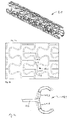
- FIG. 1 schematically shows a partial section of a stent 10 and that in a plan view of a development of its tubular circumferential wall 12.
- a main body of the stent 10 is composed entirely or in part of a plurality of support segments 14.1, 14.2, 14.3 together.
- the individual support segments 14.1, 14.2, 14.3 are aligned in the longitudinal direction of the stent 10 cross connector 16.1, 16.2, 16.3 connected with each other.
- the embodiment of the cross connector 16.1. 16.2, 16.3 is given here by way of example only. To increase bending flexibility, variants with S, V, W or other multi-sinusoidal shapes can also be used.
- the support segments 14.1, 14.2 and 14.3 of Fig. 1 comprise a zigzag or wave-shaped structure made of a respectively around the longitudinal axis of the stent 10 circumferential strut 15.1, 15.2, 15.3.
- the struts 15.1, 15.2, 15.3 in a turning region 18 of the zigzag or wavy structure, ie in the tips of the individual meanders, straight, aligned in the circumferential direction of the stent 10 bending section 20.1, 20.2, 20.3.
- the straight bending sections 20.1, 20.2 are connected to one another via linking points 22.1, 22.2 and a leg section 24.
- the transverse connectors 16.1, 16.2, 16.3 are aligned parallel to the longitudinal direction of the stent 10 and engage at attachment points 33.1, 33.2, approximately in the middle of each sixth straight bending section.
- attachment points 33.1, 33.2 approximately in the middle of each sixth straight bending section.
- other starting points and sequences are conceivable.
- the struts 15.1, 15.2, 15.3 extend in the longitudinal direction of the stent 10 in phase, i. the turning areas 18 of the individual support segments 14.1, 14.2, 14.3 have a common orientation.
- the zigzag or wavy structure shows stop elements 26 which are designed such that deformations of the zigzag or undulating structure which occur as a consequence of an expansion of the stent from the unexpanded to the expanded state, in the region of the straight bent sections 20.1, 20.2 , 20.3 and reinforced in the region of the leg portions 24.
- the stop elements 26 are formed by two webs 28.1, 28.2, which are connected at one end to the zigzag or wave-shaped structure - here by way of example at the connecting points 22.4 and 22.5.
- the webs 28.1, 28.2 are curved at their free ends 30.1, 30.2 in such a way that they are directed towards one another.
- the Fig. 2 schematically shows a partial section of another stent 9 with a plurality of juxtaposed support segments 11.1, 11.2, 11.3.
- the support segments 11.1, 11.2. 11.3 comprise a loop-shaped structure of a about the longitudinal axis of the stent 9 circumferential strut 13.1, 13.2, 13.3. Via transverse connectors 17.1, 17.2, the individual support segments 11.1, 11.2, 11.3 are connected to one another in the longitudinal extent of the stent 9.
- the illustration corresponds to a plan view of a development of the circulation wall formed from the individual support segments 11.1, 11.2, 11.3.
- the struts 13.1, 13.2, 13.3 show in the turning region 19 of the loop-shaped structure, d. H. at the tips of the individual loops, straight, aligned in the circumferential direction bending sections 21.1, 21.2.
- the straight bending sections 21.1, 21.2 are connected to each other via two connecting points 23.1, 23.2 and a slightly double-S-shaped leg section 25.
- the leg portion 25 of these loops is kept so short in relation to the straight portions 21.1, 21.2 that it almost straightens in the circumferential direction as the stents 9 expand.
- a ratio of the length to the width of the straight bending section 21.2 in the specific case is about 1: 4, wherein the length between the geometric centers of the connection points 23.1, 23.2 is measured.
- FIGS. 3a to 3c show a stent 9.1 in three-dimensional view and in enlarged detail with a comparison with the embodiment 2 almost identical design. The only deviation is that now in each turnaround 19.1 cross connector 17.3, 17.4 begin.
- Fig. 3a Its three-dimensional representation is merely an illustration of the stent design in unexpanded Status. As from the enlarged section of the 3b recognizable, the two bending sections 21.3, 21.4 are not exactly aligned in the direction of rotation of the stent 9.1 in the turning area 19.1, but show a slight deviation of about 8 °.
- Fig. 3c grips the turning area 19.1 with the two bending sections 21.3, 21.4 once again enlarged and also indicates on the basis of the dashed outline a deformation of this area upon expansion of the stent 9.1.
- FIGS. 4a to 4c show a stent 9.2 with a compared to the embodiment 3 very similar design.
- the only difference is that on the one hand the two bending sections 21.5, 21.6 are shortened in the turning area 19.2 in comparison with embodiment 3.
- the two bending sections 21.5, 21.6 in the turning region 19.2 slightly more strongly from the exact direction of rotation of the stent 9.2 from, namely by about 10 ° (see Fig. 4b and 4c).
- Fig. 4a serves to illustrate the stent design in the unexpanded state using a three-dimensional representation.
- Fig. 4c grips the turning area 19.2 with the two bending sections 21.5, 21.6 once again enlarged and also indicates on the basis of the dashed outline a deformation of this area upon expansion of the stent 9.2.
- the straight bending sections 20.1-20.3, 21.1-21.6 in the expansion of the stents 9, 9.1, 9.2, 10 are mainly claimed by a bending moment. Due to the constant lever arm or the constant moment on the said straight bending sections 20.1-20.3, 21.1-21.6, the strain is distributed evenly and local stress and strain concentrations are largely avoided, so that the low elongation at fracture of the material is taken into account.
Landscapes
- Health & Medical Sciences (AREA)
- Engineering & Computer Science (AREA)
- Veterinary Medicine (AREA)
- Vascular Medicine (AREA)
- Biomedical Technology (AREA)
- Life Sciences & Earth Sciences (AREA)
- Animal Behavior & Ethology (AREA)
- General Health & Medical Sciences (AREA)
- Public Health (AREA)
- Heart & Thoracic Surgery (AREA)
- Physics & Mathematics (AREA)
- Optics & Photonics (AREA)
- Surgery (AREA)
- Epidemiology (AREA)
- Cardiology (AREA)
- Oral & Maxillofacial Surgery (AREA)
- Transplantation (AREA)
- Media Introduction/Drainage Providing Device (AREA)
Description
- Die Erfindung betrifft Stents aus einem Material mit einer Bruchdehnung von 30% oder weniger und mit einem rohrförmigen Grundkörper, der ganz oder in Teilen aus Tragsegmenten besteht, die in Längsrichtung der Stents über Querverbinder miteinander verbunden sind, und bei denen die Tragsegmente eine zickzack- oder wellenförmige Struktur aus einer um eine Längsachse der Stents umlaufenden Strebe umfassen.
- Koronare Herzerkrankungen, insbesondere akute Myokardinfarkte, stellen in Westeuropa und Nordamerika eine der häufigsten Todesursachen dar. In mehr als 80% der Fälle ist die Ursache des Myokardinfarktes der thrombotische Verschluss einer Koronararterie durch Ruptur einer atheromatösen Plaque bei vorbestehender stenosierender Atheromatose. Entscheidende Faktoren für die Langzeitprognose nach akutem Myokardinfarkt sind:
- eine effektive und langanhaltende Wiedereröffnung der Infarktarterie,
- eine Dauer des thrombotischen Gefäßverschlusses,
- die Verhinderung eines größeren Myokardverlustes und eines ventrikulären Remodeling,
- die Beherrschung rhythmogener Komplikationen.
- Die genannten Faktoren bestimmen nicht nur die kardiovaskuläre Mortalität, sondern auch die Lebensqualität nach dem Infarkt.
- Seit mehr als zwanzig Jahren sind nicht-operative Methoden zur Stenose-Behandlung etabliert, bei denen u.a. durch Ballondilatation (PTCA Perkutane Transluminale Coronare Angioplastie) das verengte oder verschlossene Blutgefäß wieder aufgeweitet wird. Dieses Vorgehen hat sich insbesondere bei der Therapie des akuten Myokardinfarktes bewährt. Nach dem Aufweiten des Blutgefäßes entstehen in etwa einem Drittel der Fälle durch das durch die Behandlung ausgelöste Zellwachstum überdurchschnittliche Wucherungen, die letztendlich zu einer erneuten Gefäßverengung (Restenose) führen. Eine weitere Ursache der Restenose ist die Elastizität des gedehnten Blutgefäßes. Nach dem Entfernen des Ballons zieht sich das Blutgefäß übermäßig zusammen, so dass der Gefäßquerschnitt verringert wird (Obstruktion, sogenanntes negatives remodeling). Letzterer Effekt kann nur durch Platzierung eines Stents vermieden oder zumindest behindert werden.
- In der interventionellen Therapie der stabilen Angina pectoris bei koronarer Herzkrankheit, hat die Einführung der Stents zu einer deutlichen Reduktion der Rate an Restenosen und damit zu besseren Langzeitresultaten geführt. Dies gilt sowohl für die primäre als auch die Rezidivstenose. Ursächlich für den Nutzen der Stent-Implantation ist der höhere primäre Lumengewinn.
- Durch den Einsatz von Stents kann zwar ein optimaler Gefäßquerschnitt erreicht werden. Allerdings initiiert die Anwesenheit eines derartigen Fremdkörpers eine Kaskade von mikrobiologischen Prozessen, die zu einem allmählichen Zuwachsen des Stents führen können.
- Der Stent besteht in der Regel aus einem rohrförmigen Grundkörper mit einer Umfangswandung aus Streben und Querverbindern zwischen den sich Zellen unterschiedlichster Formgestaltung erstrecken. Ein gemeinsames Merkmal aller gängigen Stents besteht darin, dass ein wie auch immer geartetes Design der Stents eine Expansion von einem geschlossenen (nicht-expandierten) Zustand in einem aufgeweiteten (expandierten) Zustand ermöglichen muss. Im nicht-expandierten Zustand wird der Stent in den Bereich der Läsion des Blutgefäßes geführt. Am Applikationsort expandiert die Struktur, entweder durch von außen aufgebrachte Kräfte (z.B. mittels eines im Innern des Stents angeordneten Ballons) oder indem der Stent selbstexpandierend ausgelegt ist (z.B. durch Verwendung eines Gedächtnismaterials).
- Ein Stentdesign muss insbesondere folgenden Erfordernissen genügen:
- Im expandierten Zustand soll der Stent eine möglichst große Fläche der Gefäßwand gleichmäßig abstützen.
- Eine Expansion des Stents in radialer Richtung unterstützen, ohne eine Ausdehnung in axialer Richtung zuzulassen.
- Die einzelnen Streben und Querverbinder sollen im nicht-expandierten und expandierten Zustand sowie während des Übergangs vom nicht-expandierten zum expandierten Zustand möglichst in einer gemeinsamen radialen Umlaufebene angeordnet sein, d. h. ein Herausragen einzelner Strukturelemente muss zur Vermeidung von Gefäßverletzungen unterdrückt werden.
- Ein Versagen des Materials muss über die Dauer des Heilungs- und Implantationszeitraums vermieden werden.
- Moderne Stentdesigns tragen bei Verwendung gängiger Stentmaterialien den genannten Erfordernissen Rechnung. Beispiele solcher Stentdesigns sind beispielsweise in den Patentanmeldungen
EP 1 066 804 A2 ,US 2002/0013619 A oderWO 01/26584 A1 - Anfänglich wurden Stents zumeist aus medizinischem Stahl, z.B. 316L, hergestellt. Im Laufe der Zeit zeigte sich allerdings, dass die eingesetzten Materialien zwar biokompatibel, aber über mittlere und lange Zeiträume teils eine Thrombosebildung und teils eine Adhäsion von Biomolekülen an ihrer Oberfläche förderten. Ein Ansatzpunkt zur Lösung dieser Problematik sind Stents aus einem biodegradierbaren Material. Unter Biodegradation werden hydrolytische, enzymatische und andere stoffwechselbedingte Abbauprozesse im lebendem Organismus verstanden, die zu einer allmählichen Auflösung zumindest großer Teile des Implantats führen. So wurden beispielsweise eine Vielzahl von Kunststoffmaterialien als Stentwerkstoff vorgeschlagen, die zwar eine hohe Biokompatibilität und ein gutes Degradationsverhalten zeigten, jedoch aufgrund ihrer mechanischen Eigenschaften allenfalls eingeschränkt für die medizinische Applikation nutzbar sind.
- Zur Überwindung dieses Nachteils wird der Einsatz spezieller biodegradierbarer Metalllegierungen angestrebt, wie sie insbesondere in der
DE 197 31 021 undDE 199 45 049 - deren Offenbarung hiermit vollumfänglich einbezogen wird - beschrieben werden. Die Metalllegierungen umfassen spezielle Eisen-, Wolfram- und Magnesiumlegierungen. Die favorisierten Materialien haben allerdings zumindest teilweise den Nachteil, dass sie eine Bruchdehnung von 30% oder weniger besitzen und alle gängige Stentdesigns damit ausgeschlossen sind. So zeigt der Werkstoff 316 L eine Bruchdehnung von 40 - 50%, bestimmt an einer rohrförmigen Zugprobe mit dem Durchmesser 1,6 mm und einer Wandstärke von 0,1 mm, bei einer Probenlänge von 60 mm und einer Messlänge von 22 mm. Eine typische biodegradierbare Magnesiumlegierung hat eine Bruchdehnung von 14%, bestimmt an einer rohrförmigen Zugprobe mit dem Durchmesser 1,6 mm und einer Wandstärke von 0,2 mm, bei einer Probenlänge von 50 mm und einer Messlänge von 30 mm. - Unter dem Begriff "Bruch" wird hier die durch Überbeanspruchung hervorgerufene Trennung der Bindungen zwischen den atomaren Bestandteilen eines Werkstoffs entlang einer sich über die gesamte Breite der Werkstoffprobe erstreckenden Bruchfläche verstanden. Im Augenblick des Bruchs übersteigen die im Werkstoff durch äußere oder auch innere Kräfte aufgebauten Spannungen die werkstoffspezifische Bruchspannung und werden dadurch größer als die in der Bruchfläche wirkenden Bindungskräfte. Die Bruchfestigkeit besagt, mit welcher Kraft eine Werkstoffprobe bis zum Bruch belastbar ist. Verformungslose oder verformungsarme Brüche lassen sich mit den genannten Metalllegierungen problemlos kompensieren. Dagegen sind Verformungsbrüche wie Biege - und Torsionsbrüche mit herkömmlichen Stentdesigns unvermeidbar, denn das Material hat nur eine ungenügende Bruchdehnung.
- Unter "Bruchdehnung" wird die verbleibende Verlängerung nach einem Zugversuch bis zum Bruch, d. h. der Längenunterschied zwischen ursprünglicher Probenlänge und gebrochener Probe, bezeichnet.
- Aufgabe der vorliegenden Erfindung ist es, ein Stentdesign zu schaffen, das für Materialien mit einer Bruchdehnung von kleiner 30% geeignet ist.
- Diese Aufgabe wird durch den Stent mit den Merkmalen des Anspruchs 1 gelöst.
- Der erfindungsgemäße Stent besteht aus einer biodegradierbaren Metalllegierung mit einer Bruchdehnung von 30% oder weniger und einem rohrförmigen Grundkörper der ganz oder in Teilen aus Tragsegmenten besteht. Die Tragsegmente sind in Längsrichtung über Querverbinder miteinander verbunden und umfassen jeweils eine zickzack - oder wellenförmige Struktur aus einer um eine Längsachse des Stents umlaufenden Strebe. Der Stent zeichnet sich dadurch aus, dass die Strebe in einem Wendebereich der zickzack- oder wellenförmigen Struktur einen geraden, in Umfangsrichtung ausgerichteten Biegeabschnitt aufweist. Die erfindungsgemäßen Biegeabschnitte sind derart in das Stentdesign integriert, dass sie bei einer Expansion des Stents von einem nicht-expandierten in einen expandierten Zustand mit einem Spannungs- als auch einem Biegemoment beaufschlagt werden. Die erfindungsgemäße Ausrichtung und Form der Biegeabschnitte bezieht sich nur auf den nicht-expandierten Zustand, d.h. nach der Expansion weisen die Biegeabschnitte in der Regel eine andere Ausrichtung und Form auf. Die gerade Ausrichtung führt bei der Expansion zur gleichmäßigen Spannungs- und Dehnungsverteilung. Nur annähernd gerade Biegeabschnitte sind diesbezüglich nicht optimal und es lässt sich nur eine ähnlich, annähernd gleichmäßige Spannungs- und Dehnungsverteilung erzielen. Bei Verformung der Struktur werden diese geraden Biegeabschnitte hauptsächlich durch ein Biegemoment beansprucht. Aufgrund des konstanten Hebelarms bzw. des konstanten Moments über den gesamten geraden Biegeabschnitt verteilt sich die Dehnung gleichmäßig auf diesem Biegeabschnitt. Lokale Spannungs - und Dehnungskonzentrationen werden weitgehend vermieden und durch diese Maßnahme wird der geringen Bruchdehnung (<30%) Rechnung getragen.
- Die Schenkelabschnitte sind so kurz gehalten, dass sie sich in Umfangsrichtung bei der Expansion des Stents aufrichten. Dadurch wird ein gleichmäßiges Aufweiten des Stents geometrisch erzwungen. Das bedeutet, dass sich bei zunehmender Aufweitung die Länge des Hebelarms der Schlaufen stark verkürzt und somit wesentlich mehr Kraft nötig wird sie zu öffnen. Da die Reaktionskräfte über den Umfang für jedes Segment konstant sind, öffnen sich somit erst andere Zellen, deren Schenkelabschnitte weniger steil stehen. Die Verfestigung des Materials ist so niedrig, dass sie allein nicht ausreichend wäre, das gleichmäßige Öffnen der Struktur bei einem herkömmlichen Stentdesign zu gewährleisten. Weiterhin wird durch das Aufstellen der Schenkelabschnitte die aufgrund des niedrigen E-Moduls normalerweise hohe Recoil minimiert, da in dieser Position der Rückfederungswinkel des Stents nur einen kleinen Einfluss auf den Rückfederungsweg hat. Ein Kollapsdruck wird ebenfalls günstig beeinflusst, da die Torsionsbeanspruchung der Strebe mit deren Aufrichten deutlich abnimmt.
- In einer vorteilhaften Weiterbildung des erfindungsgemäßen Stentdesigns sind im Wendebereich der zickzack- oder wellenförmigen Struktur Anschlagelemente angeordnet. Diese sind so ausgebildet, dass Verformungen der zickzack- oder wellenförmigen Struktur, die in Folge einer Expansion von einem nicht-expandiertem in einen expandierten Zustand des Stents auftreten, im Bereich der geraden Biegeabschnitte vermindert und im Bereich der Schenkel verstärkt werden. Dies wird insbesondere dadurch erreicht, dass die Anschlagelemente jeweils aus zwei Stegen bestehen, die mit einem Ende an der zickzack- oder wellenförmigen Struktur fixiert sind. Die freien Enden der beiden Stege sind aufeinander gerichtet und so angeordnet, dass sie sich während der Expansion des Stents aufeinander zu bewegen bis sie aneinander liegen. Von diesem Zeitpunkt an wird die Verformung in den geraden Abschnitten begrenzt und in die weiteren Verformungszonen des Stents verlagert. Diese Maßnahme führt ebenfalls zu einer optimierten Verteilung der Dehnung in der Struktur.
- Nach einer weiteren bevorzugten Ausgestaltung des Stentdesigns beträgt ein Verhältnis der Länge eines gerade verlaufenden Biegeabschnitts der Strebe zu seiner Breite 1:2 bis 1:6, vorzugsweise 1:2 bis 1:3. Von der Breite und Länge der Biegeabschnitte ist deren Dicke, also deren Erstreckung in radialer Richtung, zu unterscheiden. Es hat sich gezeigt, dass die genannten Vorgaben besonders zuverlässig einen Bruch des Werkstoffs verhindern können.
- Es ist ferner bevorzugt, wenn der Stent doppel-s-förmige Schenkelabschnitte aufweist. Mit dieser Formgebung können die zuvor geschilderten günstigen Eigenschaften auf das Recoil-Verhalten und den Kollapsdruck unterstützt werden. Weiterhin ist es vorteilhaft die Schenkelabschnitte mit Sicht auf die bei der Expansion auftretenden Spannungsverhältnisse zu optimieren. Dazu wird auf die
DE 100 44 043 der Anmelderin verwiesen. Weiterhin zeigt das für die Stents verwendete Material vorzugsweise eine Bruchdehnung von 5-30%, insbesondere 10-30%, besonders bevorzugt 10-25%, besonders bevorzugt 10-20%, besonders bevorzugt 10-15%. In den sich verkleinernden Vorzugsbereichen hat sich die Verwendung des Stentdesigns gegenüber alternativen Konstruktionen als besonders geeignet erwiesen. - Ferner ist bevorzugt, wenn die Tragsegmente in Längsrichtung des Stents derart angeordnet sind, dass die zickzack- oder wellenförmigen Strukturen wenigstens zwei benachbarter Tragsegmente in Phase verlaufen. Hierdurch kann eine besonders gleichmäßige Tragstruktur im expandierten Zustand erreicht und eine Längenänderung minimiert werden.
- Vorzugsweise ist ferner die biodegradierbare Metalllegierung eine Wolfram-, Magnesium- oder Eisenlegierung.
- Vorteilhaft ist weiterhin, dass die Querverbinder parallel zur Längsrichtung des Stents ausgerichtet sind. Eine solche Anordnung unterstützt die gleichförmige Ausdehnung der Struktur während der Expansion. Zur Erhöhung der Biegeflexibilität ist es weiterhin vorteilhaft, wenn die parallel zur Längsachse des Stents verlaufenden Querverbinder S-, V-, W- oder eine andere multi-sinus-förmige Formgebung aufweisen.
- Prinzipiell ist ein Ansatzpunkt der Querverbinder frei entlang der umlaufenden zickzack - oder wellenförmigen Struktur wählbar. Es hat sich jedoch als vorteilhaft erwiesen, wenn ein Ansatzpunkt der Querverbinder im Bereich der geraden Biegeabschnitte, insbesondere in deren Mitte, liegt. Auch durch diese Maßnahme wird das Expansionsverhalten verbessert und eine gleichmäßigere Tragstruktur erzielt.
- Die Ausrichtung der erfindungsgemäßen geraden Biegeabschnitte hat in Umfangrichtung des Stents zu erfolgen, wobei leichte Abweichungen aus der Vorgaberichtung ohne eine wesentliche Verschlechterung im Expansionsverhalten tolerierbar sind. Die Abweichung liegt vorzugsweise bei < 25°, insbesondere < 20°, besonders bevorzugt < 10°. Mit anderen Worten, eine Abweichung der Ausrichtung der geraden Biegeabschnitte in Umfangrichtung des Stents beträgt höchstens 25°, insbesondere höchstens 20°, besonders bevorzugt höchstens 10°.
- Die Erfindung wird nachfolgend in Ausführungsbeispielen und anhand der dazugehörigen Zeichnungen näher erläutert. Es zeigen:
- Fig. 1
- eine schematisierte Ausschnittsansicht auf ein erfindungsgemäßes Stentdesign nach einer ersten Variante,
- Fig. 2
- eine schematisierte Ausschnittsansicht auf ein erfindungsgemäßes Stentdesign nach einer zweiten Variante,
- Fig. 3a-c
- eine dreidimensionale Ansicht eines Stents mit einem an
Fig. 2 angelehnten Stentdesign sowie vergrößerte Ausschnitte hieraus, und - Fig. 4a-c
- eine dreidimensionale Ansicht eines Stents mit einem an
Fig. 2 angelehnten Stentdesign sowie vergrößerte Ausschnitte hieraus. - Die im Folgenden beschriebenen Stents werden aus einer biodegradierbaren Metalllegierung geformt. Dazu geeignete Metalllegierungen sind in der
DE 197 31 021 undDE 199 45 049 , beschrieben. Speziell die dort beschriebenen Magnesiumlegierungen mit einer Zusammensetzung von 50-98% Magnesium, 0-40% Lithium, 0-5% Eisen und unter 5% anderer Metalle sowie die dort beschriebenen Eisenlegierungen mit einer Zusammensetzung von 88-99% Eisen, 0,5-7% Chrom und 0,5-3,5% Nickel sowie unter 5% anderer Metalle haben zumindest teilweise eine Bruchdehnung von gleich oder weniger als 30%. - Aufgrund der mechanischen Eigenschaften der genannten Werkstoffe, wie insbesondere ihrer geringen Bruchdehnung, ist ein angepasstes Design erforderlich. Dies wird nachfolgend in den Beispielen der
Fig. 1 und2 näher erläutert: - Die
Figur 1 zeigt schematisch einen Teilausschnitt eines Stents 10 und zwar in einer Draufsicht auf eine Abwicklung seiner rohrförmig verlaufenden Umlaufswandung 12. Ein Grundkörper des Stents 10 setzt sich ganz oder in Teilen aus einer Vielzahl von Tragsegmenten 14.1, 14.2, 14.3 zusammen. Die einzelnen Tragsegmente 14.1, 14.2, 14.3 sind über in Längsrichtung des Stents 10 ausgerichtete Querverbinder 16.1, 16.2, 16.3 miteinander verbunden. Die Ausgestaltung der Querverbinder 16.1. 16.2, 16.3 ist hier nur beispielhaft vorgegeben. Zur Erhöhung der Biegeflexibilität können auch Varianten mit S-, V-, W- oder anderen multi-sinus-förmigen Formgebungen genutzt werden. - Die Tragsegmente 14.1, 14.2 und 14.3 der
Fig. 1 umfassen eine zickzack- oder wellenförmige Struktur aus einer jeweils um die Längsachse des Stents 10 umlaufenden Strebe 15.1, 15.2, 15.3. Wie ersichtlich weisen die Streben 15.1, 15.2, 15.3 in einem Wendebereich 18 der zickzack- oder wellenförmigen Struktur, d.h. in den Spitzen der einzelnen Mäander, gerade, in Umfangsrichtung des Stents 10 ausgerichtete Biegeabschnitt 20.1, 20.2, 20.3 auf. Die geraden Biegeabschnitte 20.1, 20.2 sind über Verknüpfungspunkte 22.1, 22.2 und einen Schenkelabschnitt 24 miteinander verbunden. Ein Länge eines gerade verlaufenden Biegeabschnitts 20.2 der Strebe 15.1 zu seiner Breite 24 beträgt im konkreten Fall in etwa 1 zu 3,5, wobei die Länge von der geometrischen Mitte der Verknüpfungspunkte 22.1, 22.2 gemessen wird. - Die Querverbinder 16.1, 16.2, 16.3 sind parallel zur Längsrichtung des Stents 10 ausgerichtet und setzen an Ansatzpunkten 33.1, 33.2, etwa in der Mitte jedes sechsten geraden Biegeabschnitts an. Natürlich sind auch andere Ansatzpunkte und Abfolgen denkbar. Wie ersichtlich verlaufen die Streben 15.1, 15.2, 15.3 in Längsrichtung des Stents 10 in Phase, d.h. die Wendebereiche 18 der einzelnen Tragsegmente 14.1, 14.2, 14.3 weisen eine gemeinsame Ausrichtung auf.
- Weiterhin zeigt die zickzack- oder wellenförmige Struktur Anschlagelemente 26, die so ausgebildet sind, dass Verformungen der zickzack- oder wellenförmigen Struktur, die in Folge einer Expansion des Stents vom nicht-expandierten in den expandierten Zustand auftreten, im Bereich der geraden Biegeabschnitte 20.1, 20.2, 20.3 vermindert und im Bereich der Schenkelabschnitte 24 verstärkt werden. Im vorliegenden Fall werden die Anschlagelemente 26 von zwei Stegen 28.1, 28.2 gebildet, die mit einem Ende mit der zickzack- oder wellenförmigen Struktur - hier beispielhaft an den Verknüpfungspunkten 22.4 und 22.5 - verbunden sind. Die Stege 28.1, 28.2 sind an ihren freien Enden 30.1, 30.2 derart gekrümmt, dass sie aufeinander gerichtet sind. Während einer Expansion des Stents 10 bewegen sich die freien Enden 30.1, 30.2 aufeinander zu bis sie aneinander liegen. Von diesem Moment an wird eine weitere Verformung der geraden Biegeabschnitte 20.1, 20.2, 20.3 verhindert oder zumindest erschwert. In der Folge findet eine Verlagerung der Verformung in die durch die Schenkelabschnitte 24 gebildeten Verformungszonen des Stents 10 statt.
- Die
Fig. 2 zeigt schematisch einen Teilausschnitt eines weiteren Stents 9 mit einer Vielzahl von nebeneinander angeordneten Tragsegmenten 11.1, 11.2, 11.3. Die Tragsegmente 11.1, 11.2. 11.3 umfassen eine schlaufenförmige Struktur aus einer um die Längsachse des Stents 9 umlaufenden Strebe 13.1, 13.2, 13.3. Über Querverbinder 17.1, 17.2 sind die einzelnen Tragsegmente 11.1, 11.2, 11.3 in Längserstreckung des Stents 9 miteinander verbunden. Die Darstellung entspricht einer Draufsicht auf eine Abwicklung der aus den einzelnen Tragsegmenten 11.1, 11.2, 11.3 gebildeten Umlaufswandung. - Hinsichtlich der Gestaltungs- und Verknüpfungsmöglichkeiten der Querverbinder 17.1, 17.2 wird auf die im Ausführungsbeispiel 1 genannten Formgebungen verwiesen.
- Die Streben 13.1, 13.2, 13.3 zeigen im Wendebereich 19 der schlaufenförmigen Struktur, d. h. an den Spitzen der einzelnen Schlaufen, gerade, in Umfangsrichtung ausgerichtete Biegeabschnitte 21.1, 21.2. Die geraden Biegeabschnitte 21.1, 21.2 sind über zwei Verknüpfungspunkte 23.1, 23.2 und einen leicht doppel-s-förmig gestalteten Schenkelabschnitt 25 miteinander verbunden. Der Schenkelabschnitt 25 dieser Schlaufen ist im Verhältnis zu den geraden Abschnitten 21.1, 21.2 so kurz gehalten, dass er sich bei der Expansion der Stents 9 in Umfangsrichtung nahezu aufrichtet. Ein Verhältnis der Länge zur Breite des geraden Biegeabschnitt 21.2 beträgt im konkreten Fall etwa 1:4, wobei die Länge zwischen den geometrischen Mittelpunkten der Verknüpfungspunkte 23.1, 23.2 gemessen wird.
- Die
Figuren 3a bis 3c zeigen einen Stent 9.1 in dreidimensionaler Ansicht und in vergrößerten Ausschnitten mit einem im Vergleich zum Ausführungsbeispiel 2 nahezu identischen Design. Die einzige Abweichung liegt darin, dass nunmehr in jedem Wendebereich 19.1 Querverbinder 17.3, 17.4 ansetzen.Fig. 3a dient anhand seiner dreidimensionalen Darstellung lediglich der Veranschaulichung des Stentdesigns im nicht-expandierten Zustand. Wie aus dem vergrößerten Ausschnitt derFig.3b erkennbar, sind die beiden Biegeabschnitte 21.3, 21.4 im Wendebereich 19.1 nicht exakt in Umlaufrichtung des Stents 9.1 ausgerichtet, sondern zeigen eine geringe Abweichung von ca. 8°.Fig. 3c greift den Wendebereich 19.1 mit den beiden Biegeabschnitte 21.3, 21.4 noch einmal vergrößert heraus und deutet zudem anhand der gestrichelten Umrisslinie eine Verformung dieses Bereichs bei Expansion des Stent 9.1 an. - Die
Figuren 4a bis 4c zeigen einen Stent 9.2 mit einem im Vergleich zum Ausführungsbeispiel 3 sehr ähnlichen Design. Die Abweichungen liegt lediglich darin, dass zum einen die beiden Biegeabschnitte 21.5, 21.6 im Wendebereich 19.2 gegenüber Ausführungsbeispiel 3 verkürzt sind. Zum anderen weichen die beiden Biegeabschnitte 21.5, 21.6 im Wendebereich 19.2 etwas stärker von der exakten Umlaufrichtung des Stents 9.2 ab, nämlich um ca. 10° (siehe dazuFig. 4b und 4c). Fig. 4a dient der Veranschaulichung des Stentdesigns im nicht-expandierten Zustand anhand einer dreidimensionalen Darstellung.Fig. 4c greift den Wendebereich 19.2 mit den beiden Biegeabschnitte 21.5, 21.6 noch einmal vergrößert heraus und deutet zudem anhand der gestrichelten Umrisslinie eine Verformung dieses Bereichs bei Expansion des Stent 9.2 an. - Durch die geschilderten Maßnahmen gemäß der Ausführungsbeispiele 1 bis 4 lässt sich erreichen, dass die geraden Biegeabschnitte 20.1-20.3, 21.1-21.6 bei der Expansion der Stents 9, 9.1, 9.2, 10 hauptsächlich durch ein Biegemoment beansprucht werden. Aufgrund des konstanten Hebelarms bzw. des konstanten Moments über die genannten geraden Biegeabschnitte 20.1-20.3, 21.1-21.6 verteilt sich die Dehnung gleichmäßig und lokale Spannungs- und Dehnungskonzentrationen werden weitestgehend vermieden, so dass der geringen Bruchdehnung des Materials Rechnung getragen wird.
Claims (17)
- Stent (9, 9.1, 9.2, 10) aus einer biodegradierbaren Metalllegierung mit einer Bruchdehnung von 30% oder weniger und mit einem rohrförmigen Grundkörper, der ganz oder in Teilen aus Tragsegmenten (11.1-11.3, 14.1-14.3) besteht, die in Längsrichtung des Stents (9, 9.1, 9.2, 10) über Querverbinder (16.1-16.3, 17.1-17.4) miteinander verbunden sind, und die Tragsegmente (11.1-11.3, 14.1-14.3) eine zickzack - oder wellenförmige Struktur aus einer um eine Längsachse des Stents (9, 9.1, 9.2, 10) umlaufenden Strebe (13.1-13.3, 15.1-15.3) umfassen, wobei die Strebe (13.1-13.3, 15.1-15.3) in einem Wendebereich (18, 19, 19.1, 19.2) der zickzack- oder wellenförmigen Struktur einen geraden, in Umfangsrichtung ausgerichteten Biegeabschnitt (20.1-20.3, 21.1-21.6) aufweist.
- Stent nach Anspruch 1, dadurch gekennzeichnet, dass im Wendebereich (18) der zickzack- oder wellenförmigen Struktur Anschlagelemente (26) angeordnet sind, die so ausgebildet sind, dass Verformungen der zickzack- oder wellenförmigen Struktur, die infolge einer Expansion des Stents (10) von einem nicht-expandierten in einen expandierten Zustand auftreten, im Bereich der geraden Biegeabschnitte (20.1-20.3) vermindert und im Bereich der Schenkelabschnitte (24) verstärkt sind.
- Stent nach Anspruch 2, dadurch gekennzeichnet, dass die Anschlagelemente (26) jeweils aus zwei Stegen (28.1, 28.2) bestehen, die mit einem Ende an der zickzack - oder wellenförmigen Struktur fixiert sind und deren freien Enden (30.1, 30.2) aufeinander gerichtet und so angeordnet sind, dass sie sich während der Expansion des Stents (10) aufeinander zu bewegen bis sie aneinander liegen.
- Stent nach Anspruch 3, dadurch gekennzeichnet, dass die Stege (28.1, 28.2) der Anschlagelemente (26) an einem Verknüpfungspunkt (22.1, 22.2, 22.3, 22.4, 22.5) zwischen einem Schenkelabschnitt (24) und dem geraden Biegeabschnitt (20.1-20.3) angreifen.
- Stent nach Anspruch 1, dadurch gekennzeichnet, dass ein Verhältnis einer Länge zu einer Breite des gerade verlaufenden Biegeabschnitts (20.1-20.3, 21.1-21.6) der Strebe (13.1-13.3, 15.1-15.3) 1:2 bis 1:6 beträgt.
- Stent nach Anspruch 5, dadurch gekennzeichnet, dass das Verhältnis 1:2 bis 1:3 beträgt.
- Stent nach Anspruch 1, dadurch gekennzeichnet, dass das Material eine Bruchdehnung von 5 - 30% besitzt.
- Stent nach Anspruch 7, dadurch gekennzeichnet, dass das Material eine Bruchdehnung von 10-30% besitzt.
- Stent nach Anspruch 8, dadurch gekennzeichnet, dass das Material eine Bruchdehnung von 10 - 25% besitzt.
- Stent nach Anspruch 9, dadurch gekennzeichnet, dass das Material eine Bruchdehnung von 10 - 20% besitzt.
- Stent nach Anspruch 10, dadurch gekennzeichnet, dass das Material eine Bruchdehnung von 10-15% besitzt.
- Stent nach Anspruch 1, dadurch gekennzeichnet, dass die biodegradierbare Metalllegierung eine Magnesium-, Eisen-, oder Wolframlegierung ist.
- Stent nach Anspruch 1, dadurch gekennzeichnet, dass die Tragsegmente (11.1-11.3, 14.1-14.3) in Längsrichtung des Stents (9, 9.1, 9.2, 10) derart angeordnet sind, dass die zickzack- oder wellenförmigen Strukturen wenigstens zwei benachbarter Tragsegmente (11.1-11.3, 14.1-14.3) in Phase verlaufen.
- Stent nach Anspruch 1, dadurch gekennzeichnet, dass die Querverbinder (16.1-16.3, 17.1-17.4) parallel zur Längsrichtung des Stents (9, 9.1, 9.2, 10) ausgerichtet sind.
- Stent nach Anspruch 1 oder 14, dadurch gekennzeichnet, dass ein Ansatzpunkt (33.1, 33.2) der Querverbinder (16.1-16.3, 17.1-17.4) im Bereich der geraden Biegeabschnitte (20.1-20.3, 21.1-21.6) liegt.
- Stent nach Anspruch 15, dadurch gekennzeichnet, dass der Ansatzpunkt (33.1, 33.2) in der Mitte der geraden Biegeabschnitte (20.1-20.3, 21.1-21.6) liegt.
- Stent nach Anspruch 1, dadurch gekennzeichnet, dass eine Abweichung der Ausrichtung der geraden Biegeabschnitte (20.1-20.3, 21.1-21.6) in Umfangrichtung des Stents höchstens 25°, insbesondere höchstens 20°, besonders bevorzugt 10° beträgt.
Applications Claiming Priority (2)
| Application Number | Priority Date | Filing Date | Title |
|---|---|---|---|
| DE10323628A DE10323628A1 (de) | 2003-05-20 | 2003-05-20 | Stents aus einem Material geringer Bruchdehnung |
| PCT/EP2004/003999 WO2004103215A1 (de) | 2003-05-20 | 2004-04-15 | Stents aus einem material geringer bruchdehnung |
Publications (2)
| Publication Number | Publication Date |
|---|---|
| EP1624827A1 EP1624827A1 (de) | 2006-02-15 |
| EP1624827B1 true EP1624827B1 (de) | 2012-11-28 |
Family
ID=33461870
Family Applications (1)
| Application Number | Title | Priority Date | Filing Date |
|---|---|---|---|
| EP04727541A Expired - Lifetime EP1624827B1 (de) | 2003-05-20 | 2004-04-15 | Stents aus einem material geringer bruchdehnung |
Country Status (4)
| Country | Link |
|---|---|
| US (1) | US7862606B2 (de) |
| EP (1) | EP1624827B1 (de) |
| DE (1) | DE10323628A1 (de) |
| WO (1) | WO2004103215A1 (de) |
Families Citing this family (32)
| Publication number | Priority date | Publication date | Assignee | Title |
|---|---|---|---|---|
| AU2002345328A1 (en) | 2001-06-27 | 2003-03-03 | Remon Medical Technologies Ltd. | Method and device for electrochemical formation of therapeutic species in vivo |
| US8840660B2 (en) | 2006-01-05 | 2014-09-23 | Boston Scientific Scimed, Inc. | Bioerodible endoprostheses and methods of making the same |
| US8089029B2 (en) | 2006-02-01 | 2012-01-03 | Boston Scientific Scimed, Inc. | Bioabsorbable metal medical device and method of manufacture |
| US8048150B2 (en) | 2006-04-12 | 2011-11-01 | Boston Scientific Scimed, Inc. | Endoprosthesis having a fiber meshwork disposed thereon |
| JP2009545407A (ja) | 2006-08-02 | 2009-12-24 | ボストン サイエンティフィック サイムド,インコーポレイテッド | 三次元分解制御を備えたエンドプロテーゼ |
| DE102006038231A1 (de) * | 2006-08-07 | 2008-02-14 | Biotronik Vi Patent Ag | Implantat aus einem biokorrodierbaren metallischen Werkstoff mit einer Beschichtung aus einer Organosiliziumverbindung |
| WO2008034050A2 (en) * | 2006-09-15 | 2008-03-20 | Boston Scientific Limited | Endoprosthesis containing magnetic induction particles |
| CA2663303A1 (en) | 2006-09-15 | 2008-03-20 | Boston Scientific Limited | Endoprosthesis with adjustable surface features |
| JP2010503494A (ja) | 2006-09-15 | 2010-02-04 | ボストン サイエンティフィック リミテッド | 生分解性内部人工器官およびその製造方法 |
| US8052744B2 (en) | 2006-09-15 | 2011-11-08 | Boston Scientific Scimed, Inc. | Medical devices and methods of making the same |
| EP2210625B8 (de) | 2006-09-15 | 2012-02-29 | Boston Scientific Scimed, Inc. | Biologisch erodierbare Endoprothese mit biostabilen anorganischen Schichten |
| WO2008034031A2 (en) | 2006-09-15 | 2008-03-20 | Boston Scientific Limited | Bioerodible endoprostheses and methods of making the same |
| EP2081614A2 (de) * | 2006-09-15 | 2009-07-29 | Boston Scientific Scimed, Inc. | Magnetisierte bioerodierbare endoprothese |
| JP2010503482A (ja) | 2006-09-18 | 2010-02-04 | ボストン サイエンティフィック リミテッド | 内部人工器官 |
| EP2125065B1 (de) | 2006-12-28 | 2010-11-17 | Boston Scientific Limited | Bioerodierbare endoprothesen und herstellungsverfahren dafür |
| DE102007015994A1 (de) | 2007-03-16 | 2008-09-18 | Biotronik Vi Patent Ag | Stent, insbesondere aus einem Material mit geringer Bruchdehnung |
| DE102007015670A1 (de) | 2007-03-31 | 2008-10-02 | Biotronik Vi Patent Ag | Stent mit radial expandierbarem Grundkörper |
| DE102007016415A1 (de) | 2007-04-05 | 2008-10-09 | Biotronik Vi Patent Ag | Medizinisches Gefäß-Stützimplantat, insbesondere Stent |
| US8052745B2 (en) | 2007-09-13 | 2011-11-08 | Boston Scientific Scimed, Inc. | Endoprosthesis |
| US8118857B2 (en) * | 2007-11-29 | 2012-02-21 | Boston Scientific Corporation | Medical articles that stimulate endothelial cell migration |
| US7998192B2 (en) | 2008-05-09 | 2011-08-16 | Boston Scientific Scimed, Inc. | Endoprostheses |
| US20090287301A1 (en) * | 2008-05-16 | 2009-11-19 | Boston Scientific, Scimed Inc. | Coating for medical implants |
| US8236046B2 (en) | 2008-06-10 | 2012-08-07 | Boston Scientific Scimed, Inc. | Bioerodible endoprosthesis |
| US7985252B2 (en) | 2008-07-30 | 2011-07-26 | Boston Scientific Scimed, Inc. | Bioerodible endoprosthesis |
| US8382824B2 (en) | 2008-10-03 | 2013-02-26 | Boston Scientific Scimed, Inc. | Medical implant having NANO-crystal grains with barrier layers of metal nitrides or fluorides |
| WO2010101901A2 (en) | 2009-03-02 | 2010-09-10 | Boston Scientific Scimed, Inc. | Self-buffering medical implants |
| US8435281B2 (en) | 2009-04-10 | 2013-05-07 | Boston Scientific Scimed, Inc. | Bioerodible, implantable medical devices incorporating supersaturated magnesium alloys |
| WO2011119573A1 (en) | 2010-03-23 | 2011-09-29 | Boston Scientific Scimed, Inc. | Surface treated bioerodible metal endoprostheses |
| US8882824B2 (en) * | 2010-04-20 | 2014-11-11 | Cg Bio Co., Ltd. | Expanding vascular stent |
| JP2013529507A (ja) | 2010-06-21 | 2013-07-22 | ゾリオン メディカル インコーポレイテッド | 生体吸収性インプラント |
| US8986369B2 (en) | 2010-12-01 | 2015-03-24 | Zorion Medical, Inc. | Magnesium-based absorbable implants |
| US10246763B2 (en) | 2012-08-24 | 2019-04-02 | The Regents Of The University Of California | Magnesium-zinc-strontium alloys for medical implants and devices |
Family Cites Families (18)
| Publication number | Priority date | Publication date | Assignee | Title |
|---|---|---|---|---|
| EP0334045B1 (de) * | 1988-03-22 | 1994-08-17 | American Cyanamid Company | Prothetischer Artikel |
| US5733303A (en) * | 1994-03-17 | 1998-03-31 | Medinol Ltd. | Flexible expandable stent |
| CA2192520A1 (en) * | 1996-03-05 | 1997-09-05 | Ian M. Penn | Expandable stent and method for delivery of same |
| EP1066804B1 (de) | 1996-03-05 | 2004-07-14 | Evysio Medical Devices Ulc | Ausweitbarer Stent |
| US5922020A (en) * | 1996-08-02 | 1999-07-13 | Localmed, Inc. | Tubular prosthesis having improved expansion and imaging characteristics |
| US5843175A (en) * | 1997-06-13 | 1998-12-01 | Global Therapeutics, Inc. | Enhanced flexibility surgical stent |
| DE19731021A1 (de) * | 1997-07-18 | 1999-01-21 | Meyer Joerg | In vivo abbaubares metallisches Implantat |
| US6309414B1 (en) * | 1997-11-04 | 2001-10-30 | Sorin Biomedica Cardio S.P.A. | Angioplasty stents |
| AU2684499A (en) * | 1998-02-17 | 1999-08-30 | G. David Jang | Tubular stent consists of chevron-shape expansion struts and ipsilaterally attached m-frame connectors |
| US6066169A (en) * | 1998-06-02 | 2000-05-23 | Ave Connaught | Expandable stent having articulated connecting rods |
| US6293967B1 (en) | 1998-10-29 | 2001-09-25 | Conor Medsystems, Inc. | Expandable medical device with ductile hinges |
| US6273911B1 (en) * | 1999-04-22 | 2001-08-14 | Advanced Cardiovascular Systems, Inc. | Variable strength stent |
| DE19945049A1 (de) | 1999-09-20 | 2001-03-22 | Meyer Joerg | Durch Korrosion abbaubare medizinische Implantate aus Wolframlegierungen |
| AU1084101A (en) | 1999-10-14 | 2001-04-23 | United Stenting, Inc. | Stents with multilayered struts |
| DE19951475A1 (de) * | 1999-10-26 | 2001-05-10 | Biotronik Mess & Therapieg | Stent |
| DE10044043A1 (de) | 2000-08-30 | 2002-03-14 | Biotronik Mess & Therapieg | Reponierbarer Stent |
| WO2002054989A2 (en) * | 2001-01-15 | 2002-07-18 | Terumo Corp | Stent |
| US6629994B2 (en) * | 2001-06-11 | 2003-10-07 | Advanced Cardiovascular Systems, Inc. | Intravascular stent |
-
2003
- 2003-05-20 DE DE10323628A patent/DE10323628A1/de not_active Withdrawn
-
2004
- 2004-04-15 WO PCT/EP2004/003999 patent/WO2004103215A1/de not_active Ceased
- 2004-04-15 EP EP04727541A patent/EP1624827B1/de not_active Expired - Lifetime
- 2004-04-15 US US10/557,876 patent/US7862606B2/en not_active Expired - Fee Related
Also Published As
| Publication number | Publication date |
|---|---|
| US7862606B2 (en) | 2011-01-04 |
| DE10323628A1 (de) | 2004-12-30 |
| EP1624827A1 (de) | 2006-02-15 |
| WO2004103215A1 (de) | 2004-12-02 |
| US20070142899A1 (en) | 2007-06-21 |
Similar Documents
| Publication | Publication Date | Title |
|---|---|---|
| EP1624827A1 (de) | Stents aus einem material geringer bruchdehnung | |
| EP1985262B1 (de) | Stent | |
| DE69624517T2 (de) | Expandierbarer stent mit herausragenden widerhaken | |
| DE60031490T2 (de) | Stents für Angioplastie | |
| DE60211656T2 (de) | Expandierbare medizinische vorrichtung mit verriegelungsmechanismus | |
| DE10103000B4 (de) | Radial reexpandierbare Gefäßstütze | |
| DE69928915T2 (de) | Expandierbare einheitszelle und intraluminaler stent | |
| EP0847733B1 (de) | Stent | |
| DE69834170T2 (de) | Niedrig- profil selbst-expandierbarer blutgefäss stent | |
| DE60034229T2 (de) | Ausweitbarer medizinischer stent mit duktilen gelenken | |
| WO2001089414A1 (de) | Radial expandierbare gefässstütze | |
| DE10253634A1 (de) | Endoprothese | |
| EP1632256B1 (de) | Endoprothese aus einer Magnesiumlegierung | |
| DE102016110410B4 (de) | Stent, Herstellungsverfahren und Behandlungssystem | |
| DE102004045994A1 (de) | Stent zur Implantation in oder um ein Hohlorgan mit Markerelementen aus einem röntgenopaken Material | |
| DE102004022044B4 (de) | Stent | |
| EP2266508A1 (de) | Stent mit verbessertem Stentdesign | |
| EP2542192A1 (de) | Radial aufweitbarer stent | |
| DE202004014789U1 (de) | Stent zur Implantation in oder um ein Hohlorgan mit Markerelementen aus einem röntgenopaken Material | |
| DE102004012837B4 (de) | Stent mit einer Stegstruktur und Verfahren zu dessen Herstellung | |
| EP1844740B1 (de) | Selbstexpandierender Stent mit Federstruktur | |
| DE10301850A1 (de) | Stent | |
| EP4169489A1 (de) | Stent | |
| EP2332499B1 (de) | Endoprothese | |
| DE19923133B4 (de) | Radial expandierbare Gefäßstütze |
Legal Events
| Date | Code | Title | Description |
|---|---|---|---|
| PUAI | Public reference made under article 153(3) epc to a published international application that has entered the european phase |
Free format text: ORIGINAL CODE: 0009012 |
|
| 17P | Request for examination filed |
Effective date: 20051110 |
|
| AK | Designated contracting states |
Kind code of ref document: A1 Designated state(s): AT BE BG CH CY CZ DE DK EE ES FI FR GB GR HU IE IT LI LU MC NL PL PT RO SE SI SK TR |
|
| DAX | Request for extension of the european patent (deleted) | ||
| RIN1 | Information on inventor provided before grant (corrected) |
Inventor name: KOOP, KARSTEN Inventor name: BAKCZEWITZ, FRANK Inventor name: KIEKBUSCH, MARTIN Inventor name: BECHER, BAERBEL Inventor name: LOOTZ, DANIEL |
|
| 17Q | First examination report despatched |
Effective date: 20090817 |
|
| REG | Reference to a national code |
Ref country code: DE Ref legal event code: R079 Ref document number: 502004013899 Country of ref document: DE Free format text: PREVIOUS MAIN CLASS: A61F0002060000 Ipc: A61F0002900000 |
|
| GRAP | Despatch of communication of intention to grant a patent |
Free format text: ORIGINAL CODE: EPIDOSNIGR1 |
|
| RIC1 | Information provided on ipc code assigned before grant |
Ipc: A61L 31/14 20060101ALI20120711BHEP Ipc: A61F 2/90 20060101AFI20120711BHEP |
|
| GRAS | Grant fee paid |
Free format text: ORIGINAL CODE: EPIDOSNIGR3 |
|
| GRAA | (expected) grant |
Free format text: ORIGINAL CODE: 0009210 |
|
| AK | Designated contracting states |
Kind code of ref document: B1 Designated state(s): AT BE BG CH CY CZ DE DK EE ES FI FR GB GR HU IE IT LI LU MC NL PL PT RO SE SI SK TR |
|
| REG | Reference to a national code |
Ref country code: GB Ref legal event code: FG4D Free format text: NOT ENGLISH |
|
| REG | Reference to a national code |
Ref country code: CH Ref legal event code: EP |
|
| REG | Reference to a national code |
Ref country code: AT Ref legal event code: REF Ref document number: 585749 Country of ref document: AT Kind code of ref document: T Effective date: 20121215 |
|
| REG | Reference to a national code |
Ref country code: IE Ref legal event code: FG4D Free format text: LANGUAGE OF EP DOCUMENT: GERMAN |
|
| REG | Reference to a national code |
Ref country code: DE Ref legal event code: R096 Ref document number: 502004013899 Country of ref document: DE Effective date: 20130124 |
|
| REG | Reference to a national code |
Ref country code: NL Ref legal event code: T3 |
|
| PG25 | Lapsed in a contracting state [announced via postgrant information from national office to epo] |
Ref country code: ES Free format text: LAPSE BECAUSE OF FAILURE TO SUBMIT A TRANSLATION OF THE DESCRIPTION OR TO PAY THE FEE WITHIN THE PRESCRIBED TIME-LIMIT Effective date: 20130311 Ref country code: SE Free format text: LAPSE BECAUSE OF FAILURE TO SUBMIT A TRANSLATION OF THE DESCRIPTION OR TO PAY THE FEE WITHIN THE PRESCRIBED TIME-LIMIT Effective date: 20121128 Ref country code: FI Free format text: LAPSE BECAUSE OF FAILURE TO SUBMIT A TRANSLATION OF THE DESCRIPTION OR TO PAY THE FEE WITHIN THE PRESCRIBED TIME-LIMIT Effective date: 20121128 |
|
| PG25 | Lapsed in a contracting state [announced via postgrant information from national office to epo] |
Ref country code: CY Free format text: LAPSE BECAUSE OF FAILURE TO SUBMIT A TRANSLATION OF THE DESCRIPTION OR TO PAY THE FEE WITHIN THE PRESCRIBED TIME-LIMIT Effective date: 20121128 Ref country code: SI Free format text: LAPSE BECAUSE OF FAILURE TO SUBMIT A TRANSLATION OF THE DESCRIPTION OR TO PAY THE FEE WITHIN THE PRESCRIBED TIME-LIMIT Effective date: 20121128 Ref country code: PL Free format text: LAPSE BECAUSE OF FAILURE TO SUBMIT A TRANSLATION OF THE DESCRIPTION OR TO PAY THE FEE WITHIN THE PRESCRIBED TIME-LIMIT Effective date: 20121128 Ref country code: PT Free format text: LAPSE BECAUSE OF FAILURE TO SUBMIT A TRANSLATION OF THE DESCRIPTION OR TO PAY THE FEE WITHIN THE PRESCRIBED TIME-LIMIT Effective date: 20130328 Ref country code: GR Free format text: LAPSE BECAUSE OF FAILURE TO SUBMIT A TRANSLATION OF THE DESCRIPTION OR TO PAY THE FEE WITHIN THE PRESCRIBED TIME-LIMIT Effective date: 20130301 |
|
| PG25 | Lapsed in a contracting state [announced via postgrant information from national office to epo] |
Ref country code: SK Free format text: LAPSE BECAUSE OF FAILURE TO SUBMIT A TRANSLATION OF THE DESCRIPTION OR TO PAY THE FEE WITHIN THE PRESCRIBED TIME-LIMIT Effective date: 20121128 Ref country code: CZ Free format text: LAPSE BECAUSE OF FAILURE TO SUBMIT A TRANSLATION OF THE DESCRIPTION OR TO PAY THE FEE WITHIN THE PRESCRIBED TIME-LIMIT Effective date: 20121128 Ref country code: EE Free format text: LAPSE BECAUSE OF FAILURE TO SUBMIT A TRANSLATION OF THE DESCRIPTION OR TO PAY THE FEE WITHIN THE PRESCRIBED TIME-LIMIT Effective date: 20121128 Ref country code: DK Free format text: LAPSE BECAUSE OF FAILURE TO SUBMIT A TRANSLATION OF THE DESCRIPTION OR TO PAY THE FEE WITHIN THE PRESCRIBED TIME-LIMIT Effective date: 20121128 Ref country code: BG Free format text: LAPSE BECAUSE OF FAILURE TO SUBMIT A TRANSLATION OF THE DESCRIPTION OR TO PAY THE FEE WITHIN THE PRESCRIBED TIME-LIMIT Effective date: 20130228 |
|
| PG25 | Lapsed in a contracting state [announced via postgrant information from national office to epo] |
Ref country code: IT Free format text: LAPSE BECAUSE OF FAILURE TO SUBMIT A TRANSLATION OF THE DESCRIPTION OR TO PAY THE FEE WITHIN THE PRESCRIBED TIME-LIMIT Effective date: 20121128 Ref country code: RO Free format text: LAPSE BECAUSE OF FAILURE TO SUBMIT A TRANSLATION OF THE DESCRIPTION OR TO PAY THE FEE WITHIN THE PRESCRIBED TIME-LIMIT Effective date: 20121128 |
|
| PLBE | No opposition filed within time limit |
Free format text: ORIGINAL CODE: 0009261 |
|
| STAA | Information on the status of an ep patent application or granted ep patent |
Free format text: STATUS: NO OPPOSITION FILED WITHIN TIME LIMIT |
|
| BERE | Be: lapsed |
Owner name: BIOTRONIK A.G. Effective date: 20130430 |
|
| 26N | No opposition filed |
Effective date: 20130829 |
|
| PG25 | Lapsed in a contracting state [announced via postgrant information from national office to epo] |
Ref country code: MC Free format text: LAPSE BECAUSE OF FAILURE TO SUBMIT A TRANSLATION OF THE DESCRIPTION OR TO PAY THE FEE WITHIN THE PRESCRIBED TIME-LIMIT Effective date: 20121128 |
|
| REG | Reference to a national code |
Ref country code: DE Ref legal event code: R097 Ref document number: 502004013899 Country of ref document: DE Effective date: 20130829 |
|
| PG25 | Lapsed in a contracting state [announced via postgrant information from national office to epo] |
Ref country code: BE Free format text: LAPSE BECAUSE OF NON-PAYMENT OF DUE FEES Effective date: 20130430 |
|
| REG | Reference to a national code |
Ref country code: FR Ref legal event code: ST Effective date: 20131231 |
|
| PG25 | Lapsed in a contracting state [announced via postgrant information from national office to epo] |
Ref country code: FR Free format text: LAPSE BECAUSE OF NON-PAYMENT OF DUE FEES Effective date: 20130430 |
|
| REG | Reference to a national code |
Ref country code: AT Ref legal event code: MM01 Ref document number: 585749 Country of ref document: AT Kind code of ref document: T Effective date: 20130415 |
|
| PG25 | Lapsed in a contracting state [announced via postgrant information from national office to epo] |
Ref country code: AT Free format text: LAPSE BECAUSE OF NON-PAYMENT OF DUE FEES Effective date: 20130415 |
|
| PG25 | Lapsed in a contracting state [announced via postgrant information from national office to epo] |
Ref country code: TR Free format text: LAPSE BECAUSE OF FAILURE TO SUBMIT A TRANSLATION OF THE DESCRIPTION OR TO PAY THE FEE WITHIN THE PRESCRIBED TIME-LIMIT Effective date: 20121128 |
|
| PG25 | Lapsed in a contracting state [announced via postgrant information from national office to epo] |
Ref country code: HU Free format text: LAPSE BECAUSE OF FAILURE TO SUBMIT A TRANSLATION OF THE DESCRIPTION OR TO PAY THE FEE WITHIN THE PRESCRIBED TIME-LIMIT; INVALID AB INITIO Effective date: 20040415 Ref country code: LU Free format text: LAPSE BECAUSE OF NON-PAYMENT OF DUE FEES Effective date: 20130415 |
|
| PGFP | Annual fee paid to national office [announced via postgrant information from national office to epo] |
Ref country code: DE Payment date: 20210427 Year of fee payment: 18 |
|
| PGFP | Annual fee paid to national office [announced via postgrant information from national office to epo] |
Ref country code: IE Payment date: 20210422 Year of fee payment: 18 Ref country code: CH Payment date: 20210422 Year of fee payment: 18 Ref country code: GB Payment date: 20210422 Year of fee payment: 18 |
|
| PGFP | Annual fee paid to national office [announced via postgrant information from national office to epo] |
Ref country code: NL Payment date: 20210421 Year of fee payment: 18 |
|
| REG | Reference to a national code |
Ref country code: DE Ref legal event code: R119 Ref document number: 502004013899 Country of ref document: DE |
|
| REG | Reference to a national code |
Ref country code: CH Ref legal event code: PL |
|
| REG | Reference to a national code |
Ref country code: NL Ref legal event code: MM Effective date: 20220501 |
|
| GBPC | Gb: european patent ceased through non-payment of renewal fee |
Effective date: 20220415 |
|
| PG25 | Lapsed in a contracting state [announced via postgrant information from national office to epo] |
Ref country code: NL Free format text: LAPSE BECAUSE OF NON-PAYMENT OF DUE FEES Effective date: 20220501 Ref country code: LI Free format text: LAPSE BECAUSE OF NON-PAYMENT OF DUE FEES Effective date: 20220430 Ref country code: GB Free format text: LAPSE BECAUSE OF NON-PAYMENT OF DUE FEES Effective date: 20220415 Ref country code: DE Free format text: LAPSE BECAUSE OF NON-PAYMENT OF DUE FEES Effective date: 20221103 Ref country code: CH Free format text: LAPSE BECAUSE OF NON-PAYMENT OF DUE FEES Effective date: 20220430 |
|
| PG25 | Lapsed in a contracting state [announced via postgrant information from national office to epo] |
Ref country code: IE Free format text: LAPSE BECAUSE OF NON-PAYMENT OF DUE FEES Effective date: 20220415 |