EP1624552B1 - Axial gap electric motor - Google Patents
Axial gap electric motor Download PDFInfo
- Publication number
- EP1624552B1 EP1624552B1 EP05017077A EP05017077A EP1624552B1 EP 1624552 B1 EP1624552 B1 EP 1624552B1 EP 05017077 A EP05017077 A EP 05017077A EP 05017077 A EP05017077 A EP 05017077A EP 1624552 B1 EP1624552 B1 EP 1624552B1
- Authority
- EP
- European Patent Office
- Prior art keywords
- rotor
- magnets
- back core
- rotors
- core
- Prior art date
- Legal status (The legal status is an assumption and is not a legal conclusion. Google has not performed a legal analysis and makes no representation as to the accuracy of the status listed.)
- Ceased
Links
- 230000004907 flux Effects 0.000 claims description 15
- 229910000831 Steel Inorganic materials 0.000 claims description 9
- 239000010959 steel Substances 0.000 claims description 9
- 150000001875 compounds Chemical class 0.000 claims description 7
- 239000000696 magnetic material Substances 0.000 claims description 7
- 239000002184 metal Substances 0.000 claims description 3
- 238000010276 construction Methods 0.000 description 7
- 230000035515 penetration Effects 0.000 description 2
- 239000000843 powder Substances 0.000 description 2
- 239000000498 cooling water Substances 0.000 description 1
- 230000020169 heat generation Effects 0.000 description 1
- XLYOFNOQVPJJNP-UHFFFAOYSA-N water Substances O XLYOFNOQVPJJNP-UHFFFAOYSA-N 0.000 description 1
- 238000004804 winding Methods 0.000 description 1
Images


Classifications
-
- H—ELECTRICITY
- H02—GENERATION; CONVERSION OR DISTRIBUTION OF ELECTRIC POWER
- H02K—DYNAMO-ELECTRIC MACHINES
- H02K21/00—Synchronous motors having permanent magnets; Synchronous generators having permanent magnets
- H02K21/12—Synchronous motors having permanent magnets; Synchronous generators having permanent magnets with stationary armatures and rotating magnets
- H02K21/24—Synchronous motors having permanent magnets; Synchronous generators having permanent magnets with stationary armatures and rotating magnets with magnets axially facing the armatures, e.g. hub-type cycle dynamos
-
- H—ELECTRICITY
- H02—GENERATION; CONVERSION OR DISTRIBUTION OF ELECTRIC POWER
- H02K—DYNAMO-ELECTRIC MACHINES
- H02K1/00—Details of the magnetic circuit
- H02K1/06—Details of the magnetic circuit characterised by the shape, form or construction
- H02K1/22—Rotating parts of the magnetic circuit
- H02K1/27—Rotor cores with permanent magnets
- H02K1/2793—Rotors axially facing stators
- H02K1/2795—Rotors axially facing stators the rotor consisting of two or more circumferentially positioned magnets
- H02K1/2796—Rotors axially facing stators the rotor consisting of two or more circumferentially positioned magnets where both axial sides of the rotor face a stator
-
- H—ELECTRICITY
- H02—GENERATION; CONVERSION OR DISTRIBUTION OF ELECTRIC POWER
- H02K—DYNAMO-ELECTRIC MACHINES
- H02K16/00—Machines with more than one rotor or stator
Definitions
- the present invention relates to a system comprising an axial gap electric motor according to the preamble part of independent claim 1. Such a motor is shown in WO 03/069763 A1 .
- the present invention relates in general to electric motors and more particularly to the electric motors of an axial gap type which comprises a rotor shaft that is rotatable about Its axis, at least one rotor that Is fixed to the rotor shaft to rotate therewith and at least one stator that Is disposed around the rotor shaft and axially spaced from the rotor.
- the motor shown by 11-341758 comprises a cylindrical stator, an outer rotor rotatably disposed around the cylindrical stator and an Inner rotor rotatably disposed In the cylindrical stator.
- the motor shown by 2000-224836 comprises a cylindrical stator, an outer rotor rotatably arranged in a diametrically outer side in the cylindrical stator and an inner rotor rotatably arrange in a diametrically inner side in the cylindrical stator.
- axial gap electric motors are also known, some of which are of a double rotor type having two rotors that are rotatable independently from each other.
- the two rotors are rotatably arranged relative to a fixed single stator.
- Two output shafts or the like are used for the respective two rotors, that are coaxially Installed for receiving the respective torque of the two rotors.
- US 2003/0189388 A1 discloses an axial gap electric motor having two stators which are arranged at axially outer positions of two rotors. Both rotors are separated by a common end plate, which rotatably supports the axes of both rotors and which forms an intermediate wall between said both rotors.
- WO 03/069763 A1 discloses an axial gap electric motor with two rotors and a single stator.
- the two rotors are arranged co-axially and have different diameters.
- the number of N- and S-pole pairs of the second rotor is different from the number of N- and S-pole pairs of the first rotor.
- the stator comprises a core portion which is approximately U-shaped, and a compound current is supplied to the winding of said stator.
- FIG. 1 there is shown in a sectioned manner an axial gap electric motor 100 which is a first embodiment.
- Motor 100 comprises a hollow first rotor shaft 21 and a second rotor shaft 22 that is concentrically and rotatably received in first rotor shaft 21, as shown.
- First and second circular rotors 31A and 32A are concentrically connected to right ends of first and second rotor shafts 21 and 22 respectively, so that first rotor 31A and first rotor shaft 21 rotate like a single unit, and second rotor 32A and second rotor shaft 22 rotate like another single unit.
- first and second stator 42 are coaxially arranged around a common axis of first and second rotor shafts 21 and 22 in such a manner as to put therebetween first and second circular rotors 31A and 32A.
- first and second stators 41 and 42 are secured to axially opposed portions of a motor case 5 respectively.
- Motor case 5 comprises generally a circular left wall portion 51, a circular right wall portion 52 and a cylindrical intermediate wall portion 53 that extends between left and right wall portions 51 and 52, as shown.
- first stator 41 is located at a left position of first circular rotor 31A to face a left surface of rotor 31A
- second stator 42 is located at a right position of second circular rotor 32A to face a right surface of rotor 32A.
- first rotor shaft 21 is rotatably held by motor case 5 by means of two bearings 61. While, second rotor shaft 22 is rotatably held by motor case 5 by means of three bearings 62. Two of bearings 62 are used for a relative rotation between first and second rotor shafts 21 and 22, as shown.
- Each of first and second circular rotors 31A and 32A comprises a rotor back core 71 or 72, a plurality of magnets 81 or 82, a plurality of rotor cores 91 or 92 and an outer frame 101 or 102, as will be described in detail hereinafter.
- screw bolts 121 are used that extend between a raised annular portion 111 formed on first rotor shaft 21 and a base portion of rotor back core 71. More specifically, after passing through a hole formed in the base portion of rotor back core 71, each screw bolt 121 is screwed into a threaded bore formed in raised annular portion 111.
- screw bolts 122 are used that extend between a raised annular portion 112 formed on the second rotor shaft 22 and a base portion of rotor back core 72. More specifically, after passing through a hole formed in the base portion of rotor back core 72, each screw bolt 122 is screwed into a threaded bore formed in raised annular portion 112.
- Each of first and second stators 41 and 42 comprises a stator back core 131 or 132, a plurality of stator cores 141 or 142 and a plurality of stator coils 151 or 152.
- stator back core 131 is secured to the left wall surface of motor case 5, and for tight connection between second stator 42 and motor case 5, stator back core 132 is secured to the right wall surface of motor case 5, as shown.
- first encoder device 161 that senses an angular position of first rotor shaft 21.
- second encoder device 162 that senses an angular position of second rotor shaft 22.
- Motor case 5 is formed with a water jacket 17 in and through which cooling water flows to cool the motor 100.
- Each of stator cores 141 and 142 is a member in and through which magnetic fluxes flow in a direction of the common axis of first and second rotor shafts 21 and 22.
- each stator coil 151 or 152 is put around the corresponding stator core 141 or 142.
- Stator back core 131 or 132 functions to orient the magnetic fluxes of stator cores 141 or 142 around the common axis and force the magnetic fluxes to shift toward another stator core 141 or 142.
- first rotor 31A and second rotor 32A can rotate at different rotation speeds independently when first and second stators 41 and 42 are fed with a compound current, like in the above-mentioned radial gap electric motor.
- first and second stators 41 and 42 are fed with a compound current
- first and second rotors 31A and 32A are forced to rotate independently. Rotation of first rotor 31A is transmitted to an external element (not shown) through first rotor shaft 21, and rotation of second rotor 32A is transmitted to another external element (not shown) through second rotor shaft 22.
- first and second rotors 31A and 32A will be described in detail with reference to Figs. 2A, 2B , 3A and 3B .
- first rotor 31A there is shown in detail first rotor 31A.
- Fig. 2A is a partial plan view of first rotor 31A
- Fig. 2B is a development provided by developing, in a circumferential direction, portions that show a radius "r1" from a center “C1" of first rotor 31A.
- first rotor 31A comprises a rotor back core 71, a plurality of magnets 81 that are put on opposed surfaces of rotor back core 71 in a manner to have magnetic surfaces in an axial direction, rotor cores 91 each being arranged between adjacent two of magnets 81 while piercing rotor back core 71, and an outer frame 101 that tightly holds magnets 81 and rotor cores 91 relative to rotor back core 71.
- magnets 81 are arranged in a manner to alternatively change the N and S poles in a circumferential direction.
- Rotor cores 91 are constructed of a magnetic material.
- magnets 81 are arranged to constitute six pairs of magnet groups.
- Rotor back core 71 and each rotor core 91 are constructed of a plurality of flat magnetic steel sheets that are put on one another. However, if desired, such core 71 and rotor core 91 may be constructed of a pressed powder magnetic material.
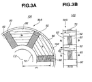
- FIG. 3A and 3B there is shown in detail second rotor 32A.
- Fig. 3A is a partial plan view of second rotor 32A
- Fig. 3B is a development provided by developing, in a circumferential direction, portions that show a radius "r1" from a center “C2" of second rotor 32A.
- second rotor 32A comprises rotor back core 72, a plurality of magnets 82 that are put on opposed surfaces of rotor back core 72 in a manner to have magnetic surfaces in an axial direction, rotor cores 92 each being arranged between adjacent two magnets 82 while piercing rotor back core 72, and outer frame 102 that tightly holds magnets 82 and rotor cores 92 relative to rotor back core 72.
- Rotor cores 92 are constructed of a magnetic material.
- magnets 82 are arranged to constitute three pairs of magnet groups.
- this second rotor 32A is substantially the same as those of the above-mentioned first rotor 31A, and thus, explanation of such constructional features will be omitted.
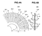
- first and second rotors 31B and 32B that are employed in a second embodiment 200.
- stator cores SC1, SC2, SC3, SC4, SC5 and SC6 of the stator 41 or 42 are illustrated in Fig. 4A or 5A by broken lines.
- first rotor 31B there is shown first rotor 31B.
- Fig. 4A is a partial plan view showing first rotor 31B as viewed behind first stator 41 illustrated by broken lines
- Fig. 4B is a development provided by developing, in a circumferential direction, portions that show a radius "r1" from a center “C1" of first rotor 31B.
- first rotor 31B comprises a rotor back core 71, a plurality of magnets 81 that are put on opposed surfaces of rotor back core 71 in a manner to have magnetic surfaces in an axial direction and an outer frame 101 that tightly holds magnets 81 relative to rotor back core 71.
- magnets 81 are arranged to constitute six pairs of magnet groups, like in the case of the first embodiment.
- this second embodiment 200 means that corresponds to rotor cores 91 employed in the above-mentioned first embodiment 100 is not employed.
- loops of reluctance-torque are not produced and thus generation of reluctance torque is not expected from first rotor 31B of this second embodiment 200.
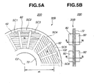
- FIG. 5A and 5B there is shown second rotor 32B.
- Fig. 5A is a partial plan view of second rotor 32B
- Fig. 5B is a development provided by developing, in a circumferential direction, portions that show a radius "r1" from a center “C2" of second rotor 32B.
- second rotor 32B comprises a rotor back core 72, a plurality of magnets 82 that are put on opposed surfaces of rotor back core 72 in a manner to have magnetic surfaces in an axial direction, and an outer frame 102 that tightly holds magnets 82 relative to rotor back core 72.
- magnets 82 are arranged to constitute three pairs of magnet groups.
- this second rotor 32B is substantially the same as those of the above-mentioned first rotor 31B, and thus, explanation of such constructional features will be omitted. Because of lack of means that corresponds to rotor cores 91, generation of reluctance torque is not expected from second rotor 32B of this second embodiment 200.
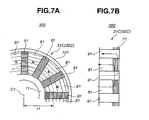
- FIG. 6 there is shown in a sectional manner an axial gap electric motor 300 which is a third embodiment.
- motor 300 of this third embodiment is similar in construction to the above-mentioned motor 100 of the first embodiment of Fig. 1 , only first and second rotors 31C and 32C that are different from those of the first embodiment 100 will be described in detail in the following.
- first rotor 31C employed in motor 300 of the third embodiment.
- first rotor 31C may be used in second rotor 32C.
- Fig. 7A is a partial plan view of first rotor 31C (or second rotor 32C)
- Fig. 7B is a development provided by developing, in a circumferential direction, portions that show a radius "r1" from a center “C1" of first rotor 31C (or second rotor 32C).
- first rotor 31C comprises a rotor back core 71, a plurality of magnets 81 that are put on one surface of rotor back core 71 in a manner to have magnetic surfaces in an axial direction, rotor cores 91 each being arranged between adjacent two magnets 81 while being embedded at one end in core back core 71, and an outer frame 101 that tightly holds magnets 81 and rotor cores 91 relative to rotor back core 71.
- Rotor back core 71 and each of rotor cores 91 are constructed of a plurality of flat magnetic steel sheets that are put on one another. However, if desired, such core 71 and rotor core 91 may be constructed of a pressed powder of magnetic material. Furthermore, if desired, rotor cores 91 may be removed like in the above-mentioned second embodiment 200.
- second rotor 32C may employ the construction of the above-mentioned first rotor 31C.
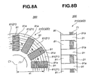
- FIG. 8A and 8B there is shown first and second rotors 31D employable in motor 300 of the third embodiment.
- first rotor 31D may be used in second rotor 32D.
- Fig. 8A is a partial plan view of first rotor 31D (or second rotor 32D)
- Fig. 8B is a development provided by developing, in a circumferential direction, portions that show a radius "r1" from a center “C1" of first rotor 31D (or second rotor 32D).
- first rotor 31D comprises a rotor back core 71, a plurality magnets 81 that are put on one surface of rotor back core 71 in a manner to have magnetic surfaces in an axial direction, and a plurality of rotor cores 91 each being arranged between adjacent two magnets 81 while piercing rotor back bore 71. It is to be noted that first rotor 31D has no means corresponding the above-mentioned outer frame 101 ( Fig. 7A ).
- each rotor core 91 has at a radially outer end thereof an enlarged flange 91a that is snugly received in a recess formed in an annular supporting member 21 that is attached to the other surface of core back core 71.
- annular supporting member 21 is constructed of a non-magnetic metal.
- first rotor 31D may be applied to second rotor 32D.
- first rotor 31D or second rotor 32D Due to provision of annular supporting member 21, first rotor 31D or second rotor 32D has a much increased mechanical strength.
- both first and second rotors 31D and 32D have the above-mentioned construction with annular supporting member 21, the flow of the magnetic flux between the two rotors 31D and 32D is much smoothed. If annular supporting member 21 is constructed of a non-magnetic metal, an eddy-current loss caused by permeation of magnetic flux can be reduced.
- an axial gap electric motor in which two rotors are independently arranged between two stators.
- the number of the magnets held by one rotor may be different from that of the magnets held by the other rotor.
- the two rotors can be independently driven while producing substantially the same torque. Because of the two stators are arranged outside of the two rotors, fixing of the two stators to the motor case is easily made.
- two rotors that is, first and second rotors (31A, 32A), (31B, 32B), (31C, 32C) or (31D, 32D) are arranged between first and second stators 41 and 42, more than two rotors may be arranged between the two stators 41 and 42.
Landscapes
- Engineering & Computer Science (AREA)
- Power Engineering (AREA)
- Permanent Magnet Type Synchronous Machine (AREA)
- Permanent Field Magnets Of Synchronous Machinery (AREA)
Description
- The present invention relates to a system comprising an axial gap electric motor according to the preamble part of independent claim 1. Such a motor is shown in
WO 03/069763 A1 - In particular, the present invention relates in general to electric motors and more particularly to the electric motors of an axial gap type which comprises a rotor shaft that is rotatable about Its axis, at least one rotor that Is fixed to the rotor shaft to rotate therewith and at least one stator that Is disposed around the rotor shaft and axially spaced from the rotor.
- Hitherto, various radial gap electric motors have been proposed and put Into practical use particularly In the field of power generators that need higher power density and lower heat generation. Some of them are disclosed In Japanese Laid-open Patent Applications, Tokkalhel 11-341758 and Tokkal 2000-224836.
- The motor shown by 11-341758 comprises a cylindrical stator, an outer rotor rotatably disposed around the cylindrical stator and an Inner rotor rotatably disposed In the cylindrical stator. While, the motor shown by 2000-224836 comprises a cylindrical stator, an outer rotor rotatably arranged in a diametrically outer side in the cylindrical stator and an inner rotor rotatably arrange in a diametrically inner side in the cylindrical stator.
- In both of the motors mentioned hereinabove, by feeding the stator with a compound current, the outer and Inner rotors are forced to rotate Independently from each other.
- In the motor of the latter reference, viz., 2000-224836, it is considerably difficult to provide the Inner rotor with a sufficient size due to the inevitable limited space defined In the diametrically Inner area of the cylindrical stator, and thus, it is difficult to expect a sufficient torque from such small sized Inner rotor. In view of this drawback, electric motors of the type of the former reference, viz., 11-341758 have been widely used in these days.
- Besides the above-mentioned radial gap electric motors, axial gap electric motors are also known, some of which are of a double rotor type having two rotors that are rotatable independently from each other. In this type electric motor, the two rotors are rotatably arranged relative to a fixed single stator. Two output shafts or the like are used for the respective two rotors, that are coaxially Installed for receiving the respective torque of the two rotors.
- When the axial gap electric motors of the above-mentioned two rotor type are constructed to be powered by a compound current, It Is necessary to arrange the two rotors at axially opposed sides of the stator respectively. However, In this case, stable supporting or holding of the stator relative to a motor case is quite difficult because of a complicated arrangement that is inevitably needed by the two rotors, the two output shafts and the single stator on a common axis.
-
US 2003/0189388 A1 discloses an axial gap electric motor having two stators which are arranged at axially outer positions of two rotors. Both rotors are separated by a common end plate, which rotatably supports the axes of both rotors and which forms an intermediate wall between said both rotors. - In
DE 10207018 A1 two motors with respective rotors and stators are separated from each other by an intermediate pump casing of a hydraulic pump. -
WO 03/069763 A1 - It is an objective of the present invention to provide a system comprising an axial gap electric motor in which the control of the first and second rotors is improved.
- According to the present invention, said objective is solved by the combination of features of independent claim 1.
- Preferred embodiments of the present invention are laid down in the subclaims.
- In the following, the present invention is explained in greater detail by means of several embodiments thereof in conjunction with the accompanying drawings, wherein:
-
Fig. 1 is a schematically illustrated sectional view of an axial gap electric motor of a first embodiment; -
Fig. 2A is a schematically illustrated plan view of a part of a first rotor employed in the electric motor of the first embodiment ofFig. 1 ; -
Fig. 2B is a development provided by developing given portions of the first rotor ofFig. 2A in a circumferential direction; -
Fig. 3A is a view similar toFig. 2A , but showing a part of a second rotor employed in the electric motor of the first embodiment ofFig. 1 ; -
Fig. 3B is a development provided by developing given portions of the second rotor ofFig. 3A in a circumferential direction; -
Fig. 4A is a view similar toFig. 2A , but showing a part of a first rotor employed in an axial gap electric motor of a second embodiment; -
Fig. 4B is a development provided by developing given portions of the first rotor ofFig. 4A in a circumferential direction; -
Fig. 5A is a view similar toFig. 4A , but showing a part of a second rotor employed in the electric motor of the second embodiment; -
Fig. 5B is a development provided by developing given portions of the second rotor ofFig. 5A in a circumferential direction; -
Fig. 6 is a view similar toFig. 1 , but showing an axial gap electric motor of a third embodiment; -
Fig. 7A is a schematically illustrated plan view of a part of a first or second rotor employed in the electric motor of the third embodiment; -
Fig. 7B is a development provided by developing given portions of the rotor ofFig. 7A in a circumferential direction; -
Fig. 8A is a schematically illustrated plan view of a part of another first or second rotor that is employable in the electric motor of the third embodiment; and -
Fig. 8B is a development provided by developing given portions of the rotor ofFig. 8A in a circumferential direction. - In the following, various embodiments will be described in detail with reference to the accompanying drawings.
- For ease of understanding, the following description includes various directional terms, such as, right, left, upper, lower, rightward and the like. However, such terms are to be understood with respect to a drawing or drawings on which a corresponding part or portion is shown. Throughout the specification, substantially the same parts or portions are denoted by the same numerals.
- Referring to
Fig. 1 , there is shown in a sectioned manner an axial gapelectric motor 100 which is a first embodiment. -
Motor 100 comprises a hollowfirst rotor shaft 21 and asecond rotor shaft 22 that is concentrically and rotatably received infirst rotor shaft 21, as shown. - First and second
circular rotors second rotor shafts first rotor 31A andfirst rotor shaft 21 rotate like a single unit, andsecond rotor 32A andsecond rotor shaft 22 rotate like another single unit. - An annular
first stator 41 and an annularsecond stator 42 are coaxially arranged around a common axis of first andsecond rotor shafts circular rotors second stators motor case 5 respectively. -
Motor case 5 comprises generally a circularleft wall portion 51, a circularright wall portion 52 and a cylindricalintermediate wall portion 53 that extends between left andright wall portions - As shown in the drawing,
first stator 41 is located at a left position of firstcircular rotor 31A to face a left surface ofrotor 31A, andsecond stator 42 is located at a right position of secondcircular rotor 32A to face a right surface ofrotor 32A. - As shown,
first rotor shaft 21 is rotatably held bymotor case 5 by means of twobearings 61. While,second rotor shaft 22 is rotatably held bymotor case 5 by means of threebearings 62. Two ofbearings 62 are used for a relative rotation between first andsecond rotor shafts - Each of first and second
circular rotors core magnets rotor cores outer frame - For tight connection between
first rotor shaft 21 andfirst rotor 31A, screwbolts 121 are used that extend between a raisedannular portion 111 formed onfirst rotor shaft 21 and a base portion of rotor backcore 71. More specifically, after passing through a hole formed in the base portion of rotor backcore 71, eachscrew bolt 121 is screwed into a threaded bore formed in raisedannular portion 111. - For tight connection between
second rotor shaft 22 and second core 32, screwbolts 122 are used that extend between a raisedannular portion 112 formed on thesecond rotor shaft 22 and a base portion of rotor backcore 72. More specifically, after passing through a hole formed in the base portion of rotor backcore 72, eachscrew bolt 122 is screwed into a threaded bore formed in raisedannular portion 112. - Each of first and
second stators core stator cores - For tight connection between
first stator 41 andmotor case 5, stator backcore 131 is secured to the left wall surface ofmotor case 5, and for tight connection betweensecond stator 42 andmotor case 5, stator backcore 132 is secured to the right wall surface ofmotor case 5, as shown. - As shown, around a left end portion of first
hollow rotor shaft 21, there is arranged afirst encoder device 161 that senses an angular position offirst rotor shaft 21. Around a right end portion ofsecond rotor shaft 22, there is arranged asecond encoder device 162 that senses an angular position ofsecond rotor shaft 22. -
Motor case 5 is formed with awater jacket 17 in and through which cooling water flows to cool themotor 100. - Each of
stator cores second rotor shafts stator coil stator core - Stator back
core stator cores stator core - It is to be noted that the number of magnetic poles of
magnets 81 that constitutefirst rotor 31A differs from the number of magnetic poles ofmagnets 82 that constitute second rotor 32. Thus,first rotor 31A andsecond rotor 32A can rotate at different rotation speeds independently when first andsecond stators - The detail of the compound current is described in
US Patent 6,291,963 granted to Masaki Nakano on September 18, 2001. - When, in operation, first and
second stators second rotors first rotor 31A is transmitted to an external element (not shown) throughfirst rotor shaft 21, and rotation ofsecond rotor 32A is transmitted to another external element (not shown) throughsecond rotor shaft 22. - In the following, the construction of first and
second rotors Figs. 2A, 2B ,3A and 3B . - Referring to
Figs. 2A and 2B , there is shown in detailfirst rotor 31A. -
Fig. 2A is a partial plan view offirst rotor 31A, andFig. 2B is a development provided by developing, in a circumferential direction, portions that show a radius "r1" from a center "C1" offirst rotor 31A. - As is seen from these drawings,
first rotor 31A comprises a rotor backcore 71, a plurality ofmagnets 81 that are put on opposed surfaces of rotor backcore 71 in a manner to have magnetic surfaces in an axial direction,rotor cores 91 each being arranged between adjacent two ofmagnets 81 while piercing rotor backcore 71, and anouter frame 101 that tightly holdsmagnets 81 androtor cores 91 relative to rotor backcore 71. - As shown,
magnets 81 are arranged in a manner to alternatively change the N and S poles in a circumferential direction. -
Rotor cores 91 are constructed of a magnetic material. - In the illustrated first embodiment,
magnets 81 are arranged to constitute six pairs of magnet groups. - Rotor back
core 71 and eachrotor core 91 are constructed of a plurality of flat magnetic steel sheets that are put on one another. However, if desired,such core 71 androtor core 91 may be constructed of a pressed powder magnetic material. - As is seen from these drawings, particularly
Fig. 2A , flat magnetic steel sheets ofrotor core 91 are piled in a radial direction with respect to center "C1" offirst rotor 31A. - Thus, as is understood from the arrows illustrated in
Fig. 2B , under operation ofmotor 100, there are produced loops of magnetic flux each flowing from a surface ofstator 41 intorotor 31A and flowing throughrotor 31A in an axial direction. - Due to the nature of the magnetic steel sheets piled in the above-mentioned manner, a tendency of shifting flowing of the magnetic flux toward a periphery of
rotor 31A is increased. Accordingly, penetration of the magnetic flux throughrotor 31A (or 32A) is carried out under the magnetic resistance being reduced in magnitude. Furthermore, due to the same reason, loops of reluctance torque are obtained, which brings about increase in torque of themotor 100 by a degree corresponding to the reluctance torque. - Referring to
Figs. 3A and 3B , there is shown in detailsecond rotor 32A. -
Fig. 3A is a partial plan view ofsecond rotor 32A, andFig. 3B is a development provided by developing, in a circumferential direction, portions that show a radius "r1" from a center "C2" ofsecond rotor 32A. - As is seen from the drawings, like in the above-mentioned
first rotor 31A,second rotor 32A comprises rotor backcore 72, a plurality ofmagnets 82 that are put on opposed surfaces of rotor backcore 72 in a manner to have magnetic surfaces in an axial direction,rotor cores 92 each being arranged between adjacent twomagnets 82 while piercing rotor backcore 72, andouter frame 102 that tightly holdsmagnets 82 androtor cores 92 relative to rotor backcore 72.Rotor cores 92 are constructed of a magnetic material. - In the illustrated
first embodiment 100,magnets 82 are arranged to constitute three pairs of magnet groups. - Other constructional features of this
second rotor 32A are substantially the same as those of the above-mentionedfirst rotor 31A, and thus, explanation of such constructional features will be omitted. - As is seen from
Figs. 3A and 3B , particularlyFig. 3A , flat magnetic steel sheets ofrotor core 92 are piled in a radial direction with respect to center "C2" ofsecond rotor 32A. Thus, as is understood from the arrows illustrated inFig. 3B , there are produced loops of magnetic flux each flowing from a surface ofstator 42 intorotor 32A and flowing throughrotor 32A in an axial direction. Due to nature of the magnetic steel sheets piled in the above-mentioned manner, a tendency of shifting flowing of the magnetic flux toward a periphery ofrotor 32A is increased, like in the above-mentionedfirst rotor 31A. Thus, penetration of the magnetic flux throughrotor 32A is carried out under the magnetic resistance being reduced in magnitude. Furthermore, due to the same reason, loops of reluctance torque are obtained, which induces increase in torque of themotor 100 like in case of first rotor 31. - Referring to
Figs. 4A and 4B , and5A and 5B , there are shown first andsecond rotors second embodiment 200. - For clarifying a positional relationship between first or
second rotor second stator stator Fig. 4A or5A by broken lines. - Referring to
Figs. 4A and 4B , there is shownfirst rotor 31B. -
Fig. 4A is a partial plan view showingfirst rotor 31B as viewed behindfirst stator 41 illustrated by broken lines, andFig. 4B is a development provided by developing, in a circumferential direction, portions that show a radius "r1" from a center "C1" offirst rotor 31B. - As is seen from these drawings,
first rotor 31B comprises a rotor backcore 71, a plurality ofmagnets 81 that are put on opposed surfaces of rotor backcore 71 in a manner to have magnetic surfaces in an axial direction and anouter frame 101 that tightly holdsmagnets 81 relative to rotor backcore 71. - Also, in this second embodiment,
magnets 81 are arranged to constitute six pairs of magnet groups, like in the case of the first embodiment. - As is understood from the above, in this
second embodiment 200, means that corresponds torotor cores 91 employed in the above-mentionedfirst embodiment 100 is not employed. Thus, as is seen fromFig. 4B , loops of reluctance-torque are not produced and thus generation of reluctance torque is not expected fromfirst rotor 31B of thissecond embodiment 200. - Referring to
Figs. 5A and 5B , there is shownsecond rotor 32B. -
Fig. 5A is a partial plan view ofsecond rotor 32B, andFig. 5B is a development provided by developing, in a circumferential direction, portions that show a radius "r1" from a center "C2" ofsecond rotor 32B. - As is seen from the drawings, like in the above-mentioned
first rotor 31B,second rotor 32B comprises a rotor backcore 72, a plurality ofmagnets 82 that are put on opposed surfaces of rotor backcore 72 in a manner to have magnetic surfaces in an axial direction, and anouter frame 102 that tightly holdsmagnets 82 relative to rotor backcore 72. - In the illustrated
second embodiment 200,magnets 82 are arranged to constitute three pairs of magnet groups. - Other constructional features of this
second rotor 32B are substantially the same as those of the above-mentionedfirst rotor 31B, and thus, explanation of such constructional features will be omitted. Because of lack of means that corresponds torotor cores 91, generation of reluctance torque is not expected fromsecond rotor 32B of thissecond embodiment 200. - Referring to
Fig. 6 , there is shown in a sectional manner an axial gapelectric motor 300 which is a third embodiment. - Since
motor 300 of this third embodiment is similar in construction to the above-mentionedmotor 100 of the first embodiment ofFig. 1 , only first andsecond rotors first embodiment 100 will be described in detail in the following. - Referring to
Figs. 7A and 7B , there is shownfirst rotor 31C employed inmotor 300 of the third embodiment. - As will be described hereinafter, the construction of
first rotor 31C may be used insecond rotor 32C. -
Fig. 7A is a partial plan view offirst rotor 31C (orsecond rotor 32C), andFig. 7B is a development provided by developing, in a circumferential direction, portions that show a radius "r1" from a center "C1" offirst rotor 31C (orsecond rotor 32C). - As is seen from the drawings, that is, from
Figs. 7A and 7B ,first rotor 31C comprises a rotor backcore 71, a plurality ofmagnets 81 that are put on one surface of rotor backcore 71 in a manner to have magnetic surfaces in an axial direction,rotor cores 91 each being arranged between adjacent twomagnets 81 while being embedded at one end in core backcore 71, and anouter frame 101 that tightly holdsmagnets 81 androtor cores 91 relative to rotor backcore 71. - Rotor back
core 71 and each ofrotor cores 91 are constructed of a plurality of flat magnetic steel sheets that are put on one another. However, if desired,such core 71 androtor core 91 may be constructed of a pressed powder of magnetic material. Furthermore, if desired,rotor cores 91 may be removed like in the above-mentionedsecond embodiment 200. - It is to be noted that
second rotor 32C may employ the construction of the above-mentionedfirst rotor 31C. - Under operation of
motor 300, there are produced loops of magnetic flux as is shown by arrows inFig. 7B . - Referring to
Figs. 8A and 8B , there is shown first andsecond rotors 31D employable inmotor 300 of the third embodiment. - As will be described hereinafter, the construction of
first rotor 31D may be used insecond rotor 32D. -
Fig. 8A is a partial plan view offirst rotor 31D (orsecond rotor 32D), andFig. 8B is a development provided by developing, in a circumferential direction, portions that show a radius "r1" from a center "C1" offirst rotor 31D (orsecond rotor 32D). - As is seen from these drawings, that is, from
Figs. 8A and 8B ,first rotor 31D comprises a rotor backcore 71, aplurality magnets 81 that are put on one surface of rotor backcore 71 in a manner to have magnetic surfaces in an axial direction, and a plurality ofrotor cores 91 each being arranged between adjacent twomagnets 81 while piercing rotor back bore 71. It is to be noted thatfirst rotor 31D has no means corresponding the above-mentioned outer frame 101 (Fig. 7A ). - As shown in
Figs. 8A and 8B , eachrotor core 91 has at a radially outer end thereof anenlarged flange 91a that is snugly received in a recess formed in an annular supportingmember 21 that is attached to the other surface of core backcore 71. - Each
rotor core 91 is welded to annular supportingmember 21. Preferably, annular supportingmember 21 is constructed of a non-magnetic metal. - As is described hereinabove, the construction of
first rotor 31D may be applied tosecond rotor 32D. - Due to provision of annular supporting
member 21,first rotor 31D orsecond rotor 32D has a much increased mechanical strength. - If both first and
second rotors member 21, the flow of the magnetic flux between the tworotors member 21 is constructed of a non-magnetic metal, an eddy-current loss caused by permeation of magnetic flux can be reduced. - As will be understood from the foregoing description, in accordance with the present teaching, there is provided an axial gap electric motor in which two rotors are independently arranged between two stators.
- The number of the magnets held by one rotor may be different from that of the magnets held by the other rotor. With this type arrangement, the two rotors can be independently driven while producing substantially the same torque. Because of the two stators are arranged outside of the two rotors, fixing of the two stators to the motor case is easily made.
- In the above-mentioned
embodiments second stators stators
Claims (15)
- System comprising an axial gap electric motor (100, 200, 300) comprising:a first and a second rotor (31A, 31 B, 31C, 31D, 32A, 32B, 32C, 32D);a number of magnetic poles of magnets (81) that constitute the first rotor (31A, 31B, 31C, 31D) differing from a number of magnetic poles of magnets (82) that constitute the second rotor (32A, 32B, 32C, 32D),characterized in thatfirst and second stators (41, 42) are arranged on mutually spaced positions of an imaginary common axis (C1, C2) in a manner to face each other;said first and second rotors (31A, 31 B, 31C, 31D, 32A, 32B, 32C, 32D) are coaxially and rotatably arranged on mutually spaced positions of the imaginary common axis (C1, C2) between the first and second stators (41, 42); andmeans are provided for feeding the first and second stators (41, 42) with a compound current for controlling said first and second rotors (31A, 31B, 31C, 31D, 32A, 32B, 32C, 32D) independently.
- System according to claim 1, wherein each of the rotors (31A, 31B, 32A, 32B) comprises a rotor back core (71, 72), and a plurality of magnets (81, 82) are put on opposed surfaces of the rotor back core (71, 72).
- System according to claim 2, wherein a plurality of rotor cores (91, 92), each being constructed of a magnetic material, is arranged between adjacent two of the magnets (81, 82) and extends through the rotor back core (71, 72).
- System according to claim 1, wherein each of the rotors (31C, 31D, 32C, 32D) comprises a rotor back core (71), and a plurality of magnets (81) that are put on one surface of the rotor back core (71).
- System according to claim 4, wherein a plurality of rotor cores (91), each being constructed of a magnetic material, is arranged between adjacent two of the magnets (81) while being embedded at one end in the core back core (71).
- System according to claim 4, wherein a plurality of rotor cores (91), each being constructed of a magnetic material, is arranged between adjacent two of the magnets (81) and extends through the rotor back core (71),
an annular supporting member is attached to the other surface of the rotor back core (71),
an enlarged flange (91 a) is formed on one axial end of each rotor core (91), and
a recess is formed in the annular supporting member to snugly receive the enlarged flange (91a). - System according to claim 6, wherein each rotor core (91) is welded to the annular supporting member.
- System according to claim 6 or 7, wherein the annular supporting member is constructed of a non-magnetic metal.
- System according to one of claims 2 to 5, wherein an outer frame (101, 102) of the rotor (31A, 31 B, 31C, 31 D, 32A, 32B, 32C, 32D) tightly holds the magnets (81, 82) relative to the rotor back core (71, 72).
- System according to claim 9, wherein the outer frame (101, 102) is also arranged to tightly hold rotor cores (91, 92) relative to the rotor back core (71, 72).
- System according to one of claims 2 to 10, wherein the rotor back core (71, 72) is constructed of a plurality of flat magnetic steel sheets that are put on one another.
- System according to one of claims 3 to 11, wherein each of the rotor cores (91, 92) is constructed of a plurality of flat magnetic steel sheets that are put on one another, and the flat magnetic steel sheets of each rotor core (91, 92) are piled in a radial direction with respect to the imaginary common axis (C1, C2).
- System according to one of claims 1 to 12, wherein the magnets (81, 82) are arranged in a manner to alternatively change N- and S- poles thereof in a circumferential direction around the imaginary common axis (C1, C2).
- System according to one of claims 1 to 13, wherein the first and second stators (41, 42) and rotors (31A, 31B, 31C, 31D, 32A, 32B, 32C, 32D) are arranged such that under operation of the motor, a first group of loops of magnetic flux is produced, each flowing from a surface of the first stator (41) into the one rotor (31A, 31 B, 31C, 31 D) that faces the first stator (41) and flowing through the one rotor in axial direction, and a second group of loops of magnetic flux is produced, each flowing from a surface of the second stator (42) into the other rotor (32A, 32B, 32C, 32D) that faces the second stator (42) and flowing through the other rotor in axial direction.
- System according to one of claims 1 to 14, wherein the first and second stators (41, 42) are coaxially arranged around the imaginary common axis (C1, C2), and the first and second rotors (31A, 31 B, 31C, 31D, 32A, 32B, 32C, 32D) are annular,
a hollow first rotor shaft (21) is rotatable about the imaginary common axis (C1, C2) and has one axial end secured to a center portion of the first rotor (31A, 31B, 31C, 31D) to rotate therewith,
a second rotor shaft (22) is rotatably received in the hollow first rotor shaft (21) and has one axial end secured to a center portion of the second rotor (32A, 32B, 32C, 32D) to rotate therewith, and
a case (5) houses the first and second stators (41, 42), the first and second rotors (31A, 31B, 31C, 31D, 32A, 32B, 32C, 32D), and the first and second rotor shafts (21, 22).
Applications Claiming Priority (1)
| Application Number | Priority Date | Filing Date | Title |
|---|---|---|---|
| JP2004230725A JP4882211B2 (en) | 2004-08-06 | 2004-08-06 | Axial gap motor structure |
Publications (2)
| Publication Number | Publication Date |
|---|---|
| EP1624552A1 EP1624552A1 (en) | 2006-02-08 |
| EP1624552B1 true EP1624552B1 (en) | 2009-03-25 |
Family
ID=35219518
Family Applications (1)
| Application Number | Title | Priority Date | Filing Date |
|---|---|---|---|
| EP05017077A Ceased EP1624552B1 (en) | 2004-08-06 | 2005-08-05 | Axial gap electric motor |
Country Status (5)
| Country | Link |
|---|---|
| US (1) | US7256524B2 (en) |
| EP (1) | EP1624552B1 (en) |
| JP (1) | JP4882211B2 (en) |
| CN (1) | CN100578898C (en) |
| DE (1) | DE602005013454D1 (en) |
Families Citing this family (35)
| Publication number | Priority date | Publication date | Assignee | Title |
|---|---|---|---|---|
| US7372182B2 (en) * | 2006-05-25 | 2008-05-13 | Deere & Company | Axial gap alternator associated with a flywheel |
| US20080100169A1 (en) * | 2006-10-31 | 2008-05-01 | Hai Tee Young | Homopolar electrical generator |
| US7800276B2 (en) * | 2007-05-17 | 2010-09-21 | Kurz-Kasch, Inc. | Rotor assembly |
| KR100948103B1 (en) * | 2007-11-20 | 2010-03-17 | 박계정 | Induction motor with multi-stage rotor that can be used as a generator |
| FR2926935B1 (en) * | 2008-01-30 | 2012-06-08 | Tecddis | AXIAL FLUX AND PERMANENT MAGNET ELECTRIC MACHINE |
| US8414471B2 (en) | 2008-10-28 | 2013-04-09 | Mobile Aspects, Inc. | Endoscope storage cabinet, tracking system, and signal emitting member |
| GB0821815D0 (en) * | 2008-11-28 | 2009-01-07 | Cummins Generator Technologies | Rotating electrical machine |
| CA2690309A1 (en) * | 2009-01-15 | 2010-07-15 | Eric Nadeau | Electric motor |
| DE102009006712A1 (en) * | 2009-01-29 | 2010-08-05 | Strothmann, Rolf, Dr.rer.nat. | Electric drive, in particular for a swivel arm |
| US20100283347A1 (en) * | 2009-05-07 | 2010-11-11 | Clynton Caines | Novel ganged alternating current generator |
| US8258737B2 (en) * | 2009-06-24 | 2012-09-04 | Casey John R | Electric machine with non-coaxial rotors |
| CN102596609B (en) | 2009-08-31 | 2015-10-07 | 复合电子系统有限责任公司 | Many induction motor (IMies and vehicle |
| CN101667768B (en) * | 2009-10-01 | 2011-04-27 | 哈尔滨工业大学 | Brushless feed claw-pole composite motor |
| US8648699B2 (en) | 2010-07-19 | 2014-02-11 | Mobile Aspects, Inc. | Item tracking system and arrangement |
| CN102931788A (en) * | 2011-12-16 | 2013-02-13 | 沈坤元 | Disc compound multi-combination three-dimensional permanent magnet motor |
| CN102624108B (en) * | 2012-03-14 | 2014-07-30 | 上海海马汽车研发有限公司 | Stator for axial clearance type motor and axial clearance type motor |
| KR101962966B1 (en) * | 2012-07-17 | 2019-03-27 | 현대모비스 주식회사 | Cooling structure for motor |
| FR2999359B1 (en) * | 2012-12-06 | 2016-07-22 | Renault Sa | ELECTRICAL MACHINE WITH INTERNAL COOLING CIRCUIT |
| JP2015019546A (en) * | 2013-07-12 | 2015-01-29 | 株式会社東芝 | Axial gap type permanent magnet rotating electric machine and manufacturing method thereof |
| US9892618B2 (en) | 2013-08-09 | 2018-02-13 | Mobile Aspects, Inc. | Signal emitting member attachment system and arrangement |
| US9806587B2 (en) | 2013-08-26 | 2017-10-31 | Robert Ross | System and method for stator construction of an electric motor |
| US9348013B2 (en) | 2013-09-18 | 2016-05-24 | Mobile Aspects, Inc. | Item hanger arrangement, system, and method |
| US9224124B2 (en) | 2013-10-29 | 2015-12-29 | Mobile Aspects, Inc. | Item storage and tracking cabinet and arrangement |
| US10034400B2 (en) | 2013-12-04 | 2018-07-24 | Mobile Aspects, Inc. | Item storage arrangement system and method |
| KR20160000909A (en) * | 2014-06-25 | 2016-01-06 | 현대모비스 주식회사 | Water-cooled moter |
| CN104393725B (en) * | 2014-12-10 | 2017-06-13 | 哈尔滨工业大学 | Axial magnetic field electromagnetic planetary gear speed changer |
| CN108667249A (en) * | 2017-03-27 | 2018-10-16 | 熵零技术逻辑工程院集团股份有限公司 | It is a kind of to rotation mechanism |
| WO2020046940A1 (en) * | 2018-08-28 | 2020-03-05 | Boston Scientific Scimed Inc | Axial flux motor for percutaneous circulatory support device |
| EP3940932A4 (en) * | 2019-08-26 | 2022-06-08 | Midea Welling Motor Technology (Shanghai) Co., Ltd | MOTOR AND FAN |
| DE102020101642A1 (en) | 2020-01-24 | 2021-07-29 | Schaeffler Technologies AG & Co. KG | Rotor, method of manufacturing a rotor and axial flux machine |
| CN111628621B (en) * | 2020-04-30 | 2022-05-17 | 陕西榆林能源集团横山煤电有限公司 | Brushless disk type double-rotor motor |
| DE102020122246A1 (en) | 2020-08-26 | 2022-03-03 | Schaeffler Technologies AG & Co. KG | Electrical machine arrangement |
| FR3117702A1 (en) * | 2020-12-16 | 2022-06-17 | Valeo Systemes Thermiques | Axial Flux Electric Motor |
| CN116054517A (en) * | 2021-10-26 | 2023-05-02 | 励富创瑞士控股有限公司 | Energy-saving brushless micro-starter generator |
| EP4328138A1 (en) * | 2022-08-22 | 2024-02-28 | Goodrich Control Systems | Motor assembly |
Family Cites Families (17)
| Publication number | Priority date | Publication date | Assignee | Title |
|---|---|---|---|---|
| JPS53116410A (en) * | 1977-03-22 | 1978-10-11 | Sony Corp | Positioning method of permanent magnet for motor |
| US5117141A (en) * | 1990-07-30 | 1992-05-26 | The United States Of America As Represented By Department Of Energy | Disc rotors with permanent magnets for brushless DC motor |
| US5955809A (en) * | 1992-08-17 | 1999-09-21 | Intellectual Property Law Department Sundstrand Corporation | Permanent magnet generator with auxiliary winding |
| FR2739505B1 (en) * | 1995-09-29 | 1997-12-19 | Technicatome | DISCOIDAL ASYNCHRONOUS ELECTRIC MOTOR |
| JP3480358B2 (en) | 1998-03-25 | 2003-12-15 | 日産自動車株式会社 | Rotating electric machine |
| JP4234831B2 (en) | 1998-12-28 | 2009-03-04 | 日本電産シバウラ株式会社 | Axial gap motor |
| JP3627559B2 (en) | 1999-01-29 | 2005-03-09 | 日産自動車株式会社 | Multilayer motor |
| US6291963B2 (en) * | 1999-12-15 | 2001-09-18 | Nissan Motor Co., Ltd. | Drive circuit for motor/generator |
| GB0100635D0 (en) | 2001-01-10 | 2001-02-21 | Newage Int Ltd | Apparatus for and method of locating magnets |
| JP2003009486A (en) * | 2001-06-26 | 2003-01-10 | Fuji Electric Co Ltd | Variable speed motor |
| JP3702825B2 (en) | 2001-09-07 | 2005-10-05 | 日産自動車株式会社 | Stator support structure for rotating electrical machines |
| US6717324B2 (en) * | 2001-10-15 | 2004-04-06 | Ming Yan Chen | Magnet motor device |
| JP3690355B2 (en) | 2002-02-12 | 2005-08-31 | 日産自動車株式会社 | Stator support structure for rotating electrical machines |
| DE10207018A1 (en) | 2002-02-20 | 2003-08-28 | Linde Ag | Unit with an electric motor and a hydraulic pump |
| US6922004B2 (en) * | 2002-04-05 | 2005-07-26 | The Timken Company | Axial flux motor assembly |
| US6977454B2 (en) * | 2003-11-12 | 2005-12-20 | Ut-Battelle Llc | Hybrid-secondary uncluttered permanent magnet machine and method |
| JP2005151725A (en) * | 2003-11-17 | 2005-06-09 | Equos Research Co Ltd | Axial gap rotating electric machine |
-
2004
- 2004-08-06 JP JP2004230725A patent/JP4882211B2/en not_active Expired - Fee Related
-
2005
- 2005-07-21 US US11/185,745 patent/US7256524B2/en not_active Expired - Lifetime
- 2005-08-05 CN CN200510089743A patent/CN100578898C/en not_active Expired - Fee Related
- 2005-08-05 DE DE602005013454T patent/DE602005013454D1/en not_active Expired - Lifetime
- 2005-08-05 EP EP05017077A patent/EP1624552B1/en not_active Ceased
Also Published As
| Publication number | Publication date |
|---|---|
| JP2006050844A (en) | 2006-02-16 |
| US7256524B2 (en) | 2007-08-14 |
| US20060028081A1 (en) | 2006-02-09 |
| CN1731654A (en) | 2006-02-08 |
| CN100578898C (en) | 2010-01-06 |
| EP1624552A1 (en) | 2006-02-08 |
| JP4882211B2 (en) | 2012-02-22 |
| DE602005013454D1 (en) | 2009-05-07 |
Similar Documents
| Publication | Publication Date | Title |
|---|---|---|
| EP1624552B1 (en) | Axial gap electric motor | |
| EP1292004B1 (en) | Two rotor single stator type electric motor | |
| US8294318B2 (en) | Electric motor and rotor for rotating electric machine | |
| US6943473B2 (en) | Electric rotating machine | |
| US7638919B2 (en) | Stator arrangement and rotor arrangement for a transverse flux machine | |
| US7315102B2 (en) | Axial gap motor | |
| JP2007526738A (en) | Device for magnetic transmission of torque | |
| JP4586717B2 (en) | motor | |
| US20040239207A1 (en) | Electronically-commutated electric motor comprising coils with parallel axes | |
| US7573176B2 (en) | Dynamo-electric machine | |
| CN111064294B (en) | Stator core and motor | |
| US6958556B2 (en) | Structure of rotors in stepping motors | |
| JP4859751B2 (en) | Rotating electric machine | |
| JP2006033989A (en) | Brushless motor | |
| CN115882630A (en) | rotating electrical machine | |
| JP4680980B2 (en) | Electric motor | |
| US20260031668A1 (en) | Multi-pole poly-phase transverse flux electric machine (motor or generator) with a 3d magnetic flux path | |
| JP7600065B2 (en) | Rotating Electric Machine | |
| US20250226709A1 (en) | Structure for an electric machine | |
| JP4691087B2 (en) | Electric motor | |
| CN115882629A (en) | Rotating electrical machine | |
| CN115882631A (en) | rotating electrical machine | |
| EP3955426A1 (en) | Rotary electric machine |
Legal Events
| Date | Code | Title | Description |
|---|---|---|---|
| PUAI | Public reference made under article 153(3) epc to a published international application that has entered the european phase |
Free format text: ORIGINAL CODE: 0009012 |
|
| 17P | Request for examination filed |
Effective date: 20050805 |
|
| AK | Designated contracting states |
Kind code of ref document: A1 Designated state(s): AT BE BG CH CY CZ DE DK EE ES FI FR GB GR HU IE IS IT LI LT LU LV MC NL PL PT RO SE SI SK TR |
|
| AX | Request for extension of the european patent |
Extension state: AL BA HR MK YU |
|
| AKX | Designation fees paid |
Designated state(s): DE FR GB |
|
| 17Q | First examination report despatched |
Effective date: 20070313 |
|
| GRAP | Despatch of communication of intention to grant a patent |
Free format text: ORIGINAL CODE: EPIDOSNIGR1 |
|
| GRAS | Grant fee paid |
Free format text: ORIGINAL CODE: EPIDOSNIGR3 |
|
| GRAA | (expected) grant |
Free format text: ORIGINAL CODE: 0009210 |
|
| AK | Designated contracting states |
Kind code of ref document: B1 Designated state(s): DE FR GB |
|
| REG | Reference to a national code |
Ref country code: GB Ref legal event code: FG4D |
|
| REF | Corresponds to: |
Ref document number: 602005013454 Country of ref document: DE Date of ref document: 20090507 Kind code of ref document: P |
|
| PLBE | No opposition filed within time limit |
Free format text: ORIGINAL CODE: 0009261 |
|
| STAA | Information on the status of an ep patent application or granted ep patent |
Free format text: STATUS: NO OPPOSITION FILED WITHIN TIME LIMIT |
|
| 26N | No opposition filed |
Effective date: 20091229 |
|
| REG | Reference to a national code |
Ref country code: FR Ref legal event code: PLFP Year of fee payment: 12 |
|
| REG | Reference to a national code |
Ref country code: FR Ref legal event code: PLFP Year of fee payment: 13 |
|
| REG | Reference to a national code |
Ref country code: FR Ref legal event code: PLFP Year of fee payment: 14 |
|
| REG | Reference to a national code |
Ref country code: FR Ref legal event code: PLFP Year of fee payment: 16 |
|
| PGFP | Annual fee paid to national office [announced via postgrant information from national office to epo] |
Ref country code: FR Payment date: 20200715 Year of fee payment: 16 Ref country code: DE Payment date: 20200722 Year of fee payment: 16 Ref country code: GB Payment date: 20200729 Year of fee payment: 16 |
|
| REG | Reference to a national code |
Ref country code: DE Ref legal event code: R119 Ref document number: 602005013454 Country of ref document: DE |
|
| GBPC | Gb: european patent ceased through non-payment of renewal fee |
Effective date: 20210805 |
|
| PG25 | Lapsed in a contracting state [announced via postgrant information from national office to epo] |
Ref country code: GB Free format text: LAPSE BECAUSE OF NON-PAYMENT OF DUE FEES Effective date: 20210805 Ref country code: FR Free format text: LAPSE BECAUSE OF NON-PAYMENT OF DUE FEES Effective date: 20210831 Ref country code: DE Free format text: LAPSE BECAUSE OF NON-PAYMENT OF DUE FEES Effective date: 20220301 |