EP1624552B1 - Elektromotor mit axialem Luftspalt - Google Patents
Elektromotor mit axialem Luftspalt Download PDFInfo
- Publication number
- EP1624552B1 EP1624552B1 EP05017077A EP05017077A EP1624552B1 EP 1624552 B1 EP1624552 B1 EP 1624552B1 EP 05017077 A EP05017077 A EP 05017077A EP 05017077 A EP05017077 A EP 05017077A EP 1624552 B1 EP1624552 B1 EP 1624552B1
- Authority
- EP
- European Patent Office
- Prior art keywords
- rotor
- magnets
- back core
- rotors
- core
- Prior art date
- Legal status (The legal status is an assumption and is not a legal conclusion. Google has not performed a legal analysis and makes no representation as to the accuracy of the status listed.)
- Ceased
Links
- 230000004907 flux Effects 0.000 claims description 15
- 229910000831 Steel Inorganic materials 0.000 claims description 9
- 239000010959 steel Substances 0.000 claims description 9
- 150000001875 compounds Chemical class 0.000 claims description 7
- 239000000696 magnetic material Substances 0.000 claims description 7
- 239000002184 metal Substances 0.000 claims description 3
- 238000010276 construction Methods 0.000 description 7
- 230000035515 penetration Effects 0.000 description 2
- 239000000843 powder Substances 0.000 description 2
- 239000000498 cooling water Substances 0.000 description 1
- 230000020169 heat generation Effects 0.000 description 1
- XLYOFNOQVPJJNP-UHFFFAOYSA-N water Substances O XLYOFNOQVPJJNP-UHFFFAOYSA-N 0.000 description 1
- 238000004804 winding Methods 0.000 description 1
Images


Classifications
-
- H—ELECTRICITY
- H02—GENERATION; CONVERSION OR DISTRIBUTION OF ELECTRIC POWER
- H02K—DYNAMO-ELECTRIC MACHINES
- H02K21/00—Synchronous motors having permanent magnets; Synchronous generators having permanent magnets
- H02K21/12—Synchronous motors having permanent magnets; Synchronous generators having permanent magnets with stationary armatures and rotating magnets
- H02K21/24—Synchronous motors having permanent magnets; Synchronous generators having permanent magnets with stationary armatures and rotating magnets with magnets axially facing the armatures, e.g. hub-type cycle dynamos
-
- H—ELECTRICITY
- H02—GENERATION; CONVERSION OR DISTRIBUTION OF ELECTRIC POWER
- H02K—DYNAMO-ELECTRIC MACHINES
- H02K1/00—Details of the magnetic circuit
- H02K1/06—Details of the magnetic circuit characterised by the shape, form or construction
- H02K1/22—Rotating parts of the magnetic circuit
- H02K1/27—Rotor cores with permanent magnets
- H02K1/2793—Rotors axially facing stators
- H02K1/2795—Rotors axially facing stators the rotor consisting of two or more circumferentially positioned magnets
- H02K1/2796—Rotors axially facing stators the rotor consisting of two or more circumferentially positioned magnets where both axial sides of the rotor face a stator
-
- H—ELECTRICITY
- H02—GENERATION; CONVERSION OR DISTRIBUTION OF ELECTRIC POWER
- H02K—DYNAMO-ELECTRIC MACHINES
- H02K16/00—Machines with more than one rotor or stator
Definitions
- the present invention relates to a system comprising an axial gap electric motor according to the preamble part of independent claim 1. Such a motor is shown in WO 03/069763 A1 .
- the present invention relates in general to electric motors and more particularly to the electric motors of an axial gap type which comprises a rotor shaft that is rotatable about Its axis, at least one rotor that Is fixed to the rotor shaft to rotate therewith and at least one stator that Is disposed around the rotor shaft and axially spaced from the rotor.
- the motor shown by 11-341758 comprises a cylindrical stator, an outer rotor rotatably disposed around the cylindrical stator and an Inner rotor rotatably disposed In the cylindrical stator.
- the motor shown by 2000-224836 comprises a cylindrical stator, an outer rotor rotatably arranged in a diametrically outer side in the cylindrical stator and an inner rotor rotatably arrange in a diametrically inner side in the cylindrical stator.
- axial gap electric motors are also known, some of which are of a double rotor type having two rotors that are rotatable independently from each other.
- the two rotors are rotatably arranged relative to a fixed single stator.
- Two output shafts or the like are used for the respective two rotors, that are coaxially Installed for receiving the respective torque of the two rotors.
- US 2003/0189388 A1 discloses an axial gap electric motor having two stators which are arranged at axially outer positions of two rotors. Both rotors are separated by a common end plate, which rotatably supports the axes of both rotors and which forms an intermediate wall between said both rotors.
- WO 03/069763 A1 discloses an axial gap electric motor with two rotors and a single stator.
- the two rotors are arranged co-axially and have different diameters.
- the number of N- and S-pole pairs of the second rotor is different from the number of N- and S-pole pairs of the first rotor.
- the stator comprises a core portion which is approximately U-shaped, and a compound current is supplied to the winding of said stator.
- FIG. 1 there is shown in a sectioned manner an axial gap electric motor 100 which is a first embodiment.
- Motor 100 comprises a hollow first rotor shaft 21 and a second rotor shaft 22 that is concentrically and rotatably received in first rotor shaft 21, as shown.
- First and second circular rotors 31A and 32A are concentrically connected to right ends of first and second rotor shafts 21 and 22 respectively, so that first rotor 31A and first rotor shaft 21 rotate like a single unit, and second rotor 32A and second rotor shaft 22 rotate like another single unit.
- first and second stator 42 are coaxially arranged around a common axis of first and second rotor shafts 21 and 22 in such a manner as to put therebetween first and second circular rotors 31A and 32A.
- first and second stators 41 and 42 are secured to axially opposed portions of a motor case 5 respectively.
- Motor case 5 comprises generally a circular left wall portion 51, a circular right wall portion 52 and a cylindrical intermediate wall portion 53 that extends between left and right wall portions 51 and 52, as shown.
- first stator 41 is located at a left position of first circular rotor 31A to face a left surface of rotor 31A
- second stator 42 is located at a right position of second circular rotor 32A to face a right surface of rotor 32A.
- first rotor shaft 21 is rotatably held by motor case 5 by means of two bearings 61. While, second rotor shaft 22 is rotatably held by motor case 5 by means of three bearings 62. Two of bearings 62 are used for a relative rotation between first and second rotor shafts 21 and 22, as shown.
- Each of first and second circular rotors 31A and 32A comprises a rotor back core 71 or 72, a plurality of magnets 81 or 82, a plurality of rotor cores 91 or 92 and an outer frame 101 or 102, as will be described in detail hereinafter.
- screw bolts 121 are used that extend between a raised annular portion 111 formed on first rotor shaft 21 and a base portion of rotor back core 71. More specifically, after passing through a hole formed in the base portion of rotor back core 71, each screw bolt 121 is screwed into a threaded bore formed in raised annular portion 111.
- screw bolts 122 are used that extend between a raised annular portion 112 formed on the second rotor shaft 22 and a base portion of rotor back core 72. More specifically, after passing through a hole formed in the base portion of rotor back core 72, each screw bolt 122 is screwed into a threaded bore formed in raised annular portion 112.
- Each of first and second stators 41 and 42 comprises a stator back core 131 or 132, a plurality of stator cores 141 or 142 and a plurality of stator coils 151 or 152.
- stator back core 131 is secured to the left wall surface of motor case 5, and for tight connection between second stator 42 and motor case 5, stator back core 132 is secured to the right wall surface of motor case 5, as shown.
- first encoder device 161 that senses an angular position of first rotor shaft 21.
- second encoder device 162 that senses an angular position of second rotor shaft 22.
- Motor case 5 is formed with a water jacket 17 in and through which cooling water flows to cool the motor 100.
- Each of stator cores 141 and 142 is a member in and through which magnetic fluxes flow in a direction of the common axis of first and second rotor shafts 21 and 22.
- each stator coil 151 or 152 is put around the corresponding stator core 141 or 142.
- Stator back core 131 or 132 functions to orient the magnetic fluxes of stator cores 141 or 142 around the common axis and force the magnetic fluxes to shift toward another stator core 141 or 142.
- first rotor 31A and second rotor 32A can rotate at different rotation speeds independently when first and second stators 41 and 42 are fed with a compound current, like in the above-mentioned radial gap electric motor.
- first and second stators 41 and 42 are fed with a compound current
- first and second rotors 31A and 32A are forced to rotate independently. Rotation of first rotor 31A is transmitted to an external element (not shown) through first rotor shaft 21, and rotation of second rotor 32A is transmitted to another external element (not shown) through second rotor shaft 22.
- first and second rotors 31A and 32A will be described in detail with reference to Figs. 2A, 2B , 3A and 3B .
- first rotor 31A there is shown in detail first rotor 31A.
- Fig. 2A is a partial plan view of first rotor 31A
- Fig. 2B is a development provided by developing, in a circumferential direction, portions that show a radius "r1" from a center “C1" of first rotor 31A.
- first rotor 31A comprises a rotor back core 71, a plurality of magnets 81 that are put on opposed surfaces of rotor back core 71 in a manner to have magnetic surfaces in an axial direction, rotor cores 91 each being arranged between adjacent two of magnets 81 while piercing rotor back core 71, and an outer frame 101 that tightly holds magnets 81 and rotor cores 91 relative to rotor back core 71.
- magnets 81 are arranged in a manner to alternatively change the N and S poles in a circumferential direction.
- Rotor cores 91 are constructed of a magnetic material.
- magnets 81 are arranged to constitute six pairs of magnet groups.
- Rotor back core 71 and each rotor core 91 are constructed of a plurality of flat magnetic steel sheets that are put on one another. However, if desired, such core 71 and rotor core 91 may be constructed of a pressed powder magnetic material.
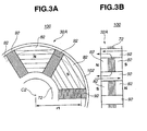
- FIG. 3A and 3B there is shown in detail second rotor 32A.
- Fig. 3A is a partial plan view of second rotor 32A
- Fig. 3B is a development provided by developing, in a circumferential direction, portions that show a radius "r1" from a center “C2" of second rotor 32A.
- second rotor 32A comprises rotor back core 72, a plurality of magnets 82 that are put on opposed surfaces of rotor back core 72 in a manner to have magnetic surfaces in an axial direction, rotor cores 92 each being arranged between adjacent two magnets 82 while piercing rotor back core 72, and outer frame 102 that tightly holds magnets 82 and rotor cores 92 relative to rotor back core 72.
- Rotor cores 92 are constructed of a magnetic material.
- magnets 82 are arranged to constitute three pairs of magnet groups.
- this second rotor 32A is substantially the same as those of the above-mentioned first rotor 31A, and thus, explanation of such constructional features will be omitted.
- first and second rotors 31B and 32B that are employed in a second embodiment 200.
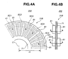
- stator cores SC1, SC2, SC3, SC4, SC5 and SC6 of the stator 41 or 42 are illustrated in Fig. 4A or 5A by broken lines.
- first rotor 31B there is shown first rotor 31B.
- Fig. 4A is a partial plan view showing first rotor 31B as viewed behind first stator 41 illustrated by broken lines
- Fig. 4B is a development provided by developing, in a circumferential direction, portions that show a radius "r1" from a center “C1" of first rotor 31B.
- first rotor 31B comprises a rotor back core 71, a plurality of magnets 81 that are put on opposed surfaces of rotor back core 71 in a manner to have magnetic surfaces in an axial direction and an outer frame 101 that tightly holds magnets 81 relative to rotor back core 71.
- magnets 81 are arranged to constitute six pairs of magnet groups, like in the case of the first embodiment.
- this second embodiment 200 means that corresponds to rotor cores 91 employed in the above-mentioned first embodiment 100 is not employed.
- loops of reluctance-torque are not produced and thus generation of reluctance torque is not expected from first rotor 31B of this second embodiment 200.
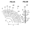
- FIG. 5A and 5B there is shown second rotor 32B.
- Fig. 5A is a partial plan view of second rotor 32B
- Fig. 5B is a development provided by developing, in a circumferential direction, portions that show a radius "r1" from a center “C2" of second rotor 32B.
- second rotor 32B comprises a rotor back core 72, a plurality of magnets 82 that are put on opposed surfaces of rotor back core 72 in a manner to have magnetic surfaces in an axial direction, and an outer frame 102 that tightly holds magnets 82 relative to rotor back core 72.
- magnets 82 are arranged to constitute three pairs of magnet groups.
- this second rotor 32B is substantially the same as those of the above-mentioned first rotor 31B, and thus, explanation of such constructional features will be omitted. Because of lack of means that corresponds to rotor cores 91, generation of reluctance torque is not expected from second rotor 32B of this second embodiment 200.
- FIG. 6 there is shown in a sectional manner an axial gap electric motor 300 which is a third embodiment.
- motor 300 of this third embodiment is similar in construction to the above-mentioned motor 100 of the first embodiment of Fig. 1 , only first and second rotors 31C and 32C that are different from those of the first embodiment 100 will be described in detail in the following.
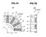
- first rotor 31C employed in motor 300 of the third embodiment.
- first rotor 31C may be used in second rotor 32C.
- Fig. 7A is a partial plan view of first rotor 31C (or second rotor 32C)
- Fig. 7B is a development provided by developing, in a circumferential direction, portions that show a radius "r1" from a center “C1" of first rotor 31C (or second rotor 32C).
- first rotor 31C comprises a rotor back core 71, a plurality of magnets 81 that are put on one surface of rotor back core 71 in a manner to have magnetic surfaces in an axial direction, rotor cores 91 each being arranged between adjacent two magnets 81 while being embedded at one end in core back core 71, and an outer frame 101 that tightly holds magnets 81 and rotor cores 91 relative to rotor back core 71.
- Rotor back core 71 and each of rotor cores 91 are constructed of a plurality of flat magnetic steel sheets that are put on one another. However, if desired, such core 71 and rotor core 91 may be constructed of a pressed powder of magnetic material. Furthermore, if desired, rotor cores 91 may be removed like in the above-mentioned second embodiment 200.
- second rotor 32C may employ the construction of the above-mentioned first rotor 31C.
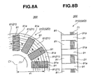
- FIG. 8A and 8B there is shown first and second rotors 31D employable in motor 300 of the third embodiment.
- first rotor 31D may be used in second rotor 32D.
- Fig. 8A is a partial plan view of first rotor 31D (or second rotor 32D)
- Fig. 8B is a development provided by developing, in a circumferential direction, portions that show a radius "r1" from a center “C1" of first rotor 31D (or second rotor 32D).
- first rotor 31D comprises a rotor back core 71, a plurality magnets 81 that are put on one surface of rotor back core 71 in a manner to have magnetic surfaces in an axial direction, and a plurality of rotor cores 91 each being arranged between adjacent two magnets 81 while piercing rotor back bore 71. It is to be noted that first rotor 31D has no means corresponding the above-mentioned outer frame 101 ( Fig. 7A ).
- each rotor core 91 has at a radially outer end thereof an enlarged flange 91a that is snugly received in a recess formed in an annular supporting member 21 that is attached to the other surface of core back core 71.
- annular supporting member 21 is constructed of a non-magnetic metal.
- first rotor 31D may be applied to second rotor 32D.
- first rotor 31D or second rotor 32D Due to provision of annular supporting member 21, first rotor 31D or second rotor 32D has a much increased mechanical strength.
- both first and second rotors 31D and 32D have the above-mentioned construction with annular supporting member 21, the flow of the magnetic flux between the two rotors 31D and 32D is much smoothed. If annular supporting member 21 is constructed of a non-magnetic metal, an eddy-current loss caused by permeation of magnetic flux can be reduced.
- an axial gap electric motor in which two rotors are independently arranged between two stators.
- the number of the magnets held by one rotor may be different from that of the magnets held by the other rotor.
- the two rotors can be independently driven while producing substantially the same torque. Because of the two stators are arranged outside of the two rotors, fixing of the two stators to the motor case is easily made.
- two rotors that is, first and second rotors (31A, 32A), (31B, 32B), (31C, 32C) or (31D, 32D) are arranged between first and second stators 41 and 42, more than two rotors may be arranged between the two stators 41 and 42.
Landscapes
- Engineering & Computer Science (AREA)
- Power Engineering (AREA)
- Permanent Magnet Type Synchronous Machine (AREA)
- Permanent Field Magnets Of Synchronous Machinery (AREA)
Claims (15)
- System, aufweisend einen Axialspalt- Elektromotor (100, 200, 300), aufweisend:einen ersten und zweiten Rotor (31A, 31B, 31C, 31D, 32A, 32B, 32C, 32D);eine Anzahl von Magnetpolen von Magneten (81), die den ersten Rotor (31A, 31B, 31C, 31D) bilden, die von einer Anzahl von Magnetpolen der Magnete (82), die den zweiten Rotor 32A, 32B, 32C, 32D) bilden, verschieden ist,dadurch gekennzeichnet, dassdie ersten und zweiten Statoren (41, 42) in voneinander beabstandeten Positionen von einer gedachten gemeinsamen Achse (C1, C2) in einer Weise angeordnet sind, um einander zugewandt zu sein;die ersten und zweiten Rotoren (31A, 31B, 31C, 31D, 32A, 32B, 32C, 32D) koaxial und drehbar in voneinander beabstandeten Positionen von der gedachten gemeinsamen Achse (C1, C2) zwischen den ersten und zweiten Statoren (41, 42) angeordnet sind; undMittel vorgesehen sind, um die ersten und zweiten Statoren (41, 42) mit einem Sammelstrom zu versorgen, um die ersten und zweiten Rotoren (31A, 31B, 31C, 31D, 32A, 32B, 32C, 32D) unabhängig zu steuern.
- System nach Anspruch 1, wobei jeder der Rotoren (31A, 31 B, 32A, 32B) einen Rotorrückkem (71, 72) aufweist und eine Mehrzahl von Magneten (81, 82) auf gegenüberliegende Oberflächen des Rotorrückkems (71, 72) aufgebracht ist.
- System nach Anspruch 2, wobei eine Mehrzahl von Rotorkernen (91, 92), jeweils aufgebaut aus einem magnetischen Material, zwischen benachbarten zwei der Magnete (81, 82) angeordnet ist und sich durch den Rotorrückkem (71, 72) erstreckt.
- System nach Anspruch 1, wobei jeder der Rotoren (31C, 31D, 32C, 32D) einen Rotorrückkem (71) und eine Mehrzahl von Magneten (81), die auf eine Oberfläche des Rotorrückkems (71) aufgebracht ist, aufweist.
- System nach Anspruch 4, wobei eine Mehrzahl von Rotorkernen (91), jeweils aufgebaut aus einem magnetischen Material, zwischen benachbarten zwei der Magnete (81) angeordnet ist, während sie an einem Ende in dem Rotorrückkern (71) eingebettet sind.
- System nach Anspruch 4, wobei eine Mehrzahl von Rotorkernen (91), jeweils aufgebaut aus einem magnetischen Material, zwischen benachbarten zwei der Magnete (81) angeordnet ist und sich durch den Rotorrückkem (71) erstreckt, ein ringförmiges Lagerteil mit der anderen Oberfläche des Rotorrückkerns (71) verbunden ist,
ein vergrößerter Flansch (91 a) an einem axialen Ende von jedem Rotorkern (91) gebildet ist und
eine Aussparung in dem ringförmigen Lagerteil gebildet ist, um den vergrößerten Flansch (91 a) eng anliegend aufzunehmen. - System nach Anspruch 6, wobei jeder Rotorkern (91) an dem ringförmigen Lagerteil verschweißt ist.
- System nach Anspruch 6 oder 7, wobei das ringförmige Lagerteil aus einem nichtmagnetischen Metall aufgebaut ist.
- System nach einem der Ansprüche 2 bis 5, wobei ein äußerer Rahmen (101, 102) des Rotors (31A, 31B, 31C, 31 D, 32A, 32B, 32C, 32D) die Magnete (81, 82) relativ zu dem Rotorrückkern (71, 72) fest hält.
- System nach Anspruch 9, wobei der äußere Rahmen (101, 102) auch vorgesehen ist, die Rotorkerne (91, 92) relativ zu dem Rotorrückkern (71, 72) fest zu halten.
- System nach einem der Ansprüche 2 bis 10, wobei der Rotorrückkern (71, 72) aus einer Mehrzahl von flachen, magnetischen Stahlblechen, die übereinander gelegt sind, aufgebaut ist.
- System nach einem der Ansprüche 3 bis 11, wobei jeder der Rotorkerne (91, 92) aus einer Mehrzahl von flachen, magnetischen Stahlblechen, die übereinander gelegt sind, aufgebaut ist und die flachen, magnetischen Stahlbleche von jedem Rotorkern (91, 92) in einer radialen Richtung in Bezug auf die gedachte gemeinsame Achse (C1, C2) gestapelt sind.
- System nach einem der Ansprüche 1 bis 12, wobei die Magnete (81, 82) in einer Weise angeordnet sind, um alternierend N- und S- Pole derselben in einer Umfangsrichtung rund um die gedachte gemeinsame Achse (C1, C2) zu ändern.
- System nach einem der Ansprüche 1 bis 13, wobei die ersten und zweiten Rotoren (31A, 31 B, 31C, 31D, 32A, 32B, 32C, 32D) derart angeordnet ist, dass während des Betriebs des Motors eine erste Gruppe von magnetischen Flusskreisen erzeugt wird, jeweils fließend von einer Oberfläche des ersten Stators (41) in den einen Rotor (31A, 31B, 31C, 31D), der dem ersten Stator (41) zugewandt ist, und durch den einen Rotor in axialer Richtung, und eine zweite Gruppe con magnetischen Flusskreisen erzeugt wird, jeweils fließend von einer Oberfläche des zweiten Stators (42) in den anderen Rotor (32A, 32B, 32C, 32D), der dem zweiten Stator (42) zugewandt ist, und durch den anderen Rotor in axialer Richtung.
- System nach einem der Ansprüche 1 bis 14, wobei die ersten und zweiten Statoren (41, 42) koaxial rund um die gedachte gemeinsame Achse (C1, C2) angeordnet sind und die ersten und zweiten Rotoren (31A, 31B, 31C, 31D, 32A, 32B, 32C, 32D) ringförmig sind,
eine hohle erste Rotorwelle (21) drehbar um die gedachte gemeinsame Achse (C1, C2) ist und ein axiales Ende hat, das an einem Mittelabschnitt des ersten Rotors (31A, 31B, 31C, 31D) befestigt ist, um sich mit diesem zu drehen, eine zweite Rotorwelle (22), die drehbar in der hohlen ersten Rotorwelle (21) aufgenommen ist und ein Ende hat, befestigt an einem Mittelabschnitt des zweiten Rotors (32A, 32B, 32C, 32D), um sich mit diesem zu drehen, und ein Gehäuse (5) die ersten und zweiten Statoren (41, 42), die ersten und zweiten Rotoren (31A, 31 B, 31C, 31D, 32A, 32B, 32C, 32D) und die ersten und zweiten Rotorwellen (21, 22) aufnimmt.
Applications Claiming Priority (1)
| Application Number | Priority Date | Filing Date | Title |
|---|---|---|---|
| JP2004230725A JP4882211B2 (ja) | 2004-08-06 | 2004-08-06 | アキシャルギャップモータの構造 |
Publications (2)
| Publication Number | Publication Date |
|---|---|
| EP1624552A1 EP1624552A1 (de) | 2006-02-08 |
| EP1624552B1 true EP1624552B1 (de) | 2009-03-25 |
Family
ID=35219518
Family Applications (1)
| Application Number | Title | Priority Date | Filing Date |
|---|---|---|---|
| EP05017077A Ceased EP1624552B1 (de) | 2004-08-06 | 2005-08-05 | Elektromotor mit axialem Luftspalt |
Country Status (5)
| Country | Link |
|---|---|
| US (1) | US7256524B2 (de) |
| EP (1) | EP1624552B1 (de) |
| JP (1) | JP4882211B2 (de) |
| CN (1) | CN100578898C (de) |
| DE (1) | DE602005013454D1 (de) |
Families Citing this family (35)
| Publication number | Priority date | Publication date | Assignee | Title |
|---|---|---|---|---|
| US7372182B2 (en) * | 2006-05-25 | 2008-05-13 | Deere & Company | Axial gap alternator associated with a flywheel |
| US20080100169A1 (en) * | 2006-10-31 | 2008-05-01 | Hai Tee Young | Homopolar electrical generator |
| US7800276B2 (en) * | 2007-05-17 | 2010-09-21 | Kurz-Kasch, Inc. | Rotor assembly |
| KR100948103B1 (ko) * | 2007-11-20 | 2010-03-17 | 박계정 | 발전기로 사용이 가능한 다단 회전자를 구비한 유도모터 |
| FR2926935B1 (fr) * | 2008-01-30 | 2012-06-08 | Tecddis | Machine electrique a flux axial et a aimants permanents |
| US8414471B2 (en) | 2008-10-28 | 2013-04-09 | Mobile Aspects, Inc. | Endoscope storage cabinet, tracking system, and signal emitting member |
| GB0821815D0 (en) * | 2008-11-28 | 2009-01-07 | Cummins Generator Technologies | Rotating electrical machine |
| CA2690309A1 (en) * | 2009-01-15 | 2010-07-15 | Eric Nadeau | Electric motor |
| DE102009006712A1 (de) * | 2009-01-29 | 2010-08-05 | Strothmann, Rolf, Dr.rer.nat. | Elektrischer Antrieb, insbesondere für einen Schwenkarm |
| US20100283347A1 (en) * | 2009-05-07 | 2010-11-11 | Clynton Caines | Novel ganged alternating current generator |
| US8258737B2 (en) * | 2009-06-24 | 2012-09-04 | Casey John R | Electric machine with non-coaxial rotors |
| CN102596609B (zh) | 2009-08-31 | 2015-10-07 | 复合电子系统有限责任公司 | 多感应电动机和车辆 |
| CN101667768B (zh) * | 2009-10-01 | 2011-04-27 | 哈尔滨工业大学 | 无刷馈电爪极复合电机 |
| US8648699B2 (en) | 2010-07-19 | 2014-02-11 | Mobile Aspects, Inc. | Item tracking system and arrangement |
| CN102931788A (zh) * | 2011-12-16 | 2013-02-13 | 沈坤元 | 一种碟形复式多组合三维永磁电机 |
| CN102624108B (zh) * | 2012-03-14 | 2014-07-30 | 上海海马汽车研发有限公司 | 轴向间隙型电动机的定子及轴向间隙型电动机 |
| KR101962966B1 (ko) * | 2012-07-17 | 2019-03-27 | 현대모비스 주식회사 | 모터 냉각구조 |
| FR2999359B1 (fr) * | 2012-12-06 | 2016-07-22 | Renault Sa | Machine electrique dotee d'un circuit de refroidissement interne |
| JP2015019546A (ja) * | 2013-07-12 | 2015-01-29 | 株式会社東芝 | アキシャルギャップ型永久磁石回転電機およびその製造方法 |
| US9892618B2 (en) | 2013-08-09 | 2018-02-13 | Mobile Aspects, Inc. | Signal emitting member attachment system and arrangement |
| US9806587B2 (en) | 2013-08-26 | 2017-10-31 | Robert Ross | System and method for stator construction of an electric motor |
| US9348013B2 (en) | 2013-09-18 | 2016-05-24 | Mobile Aspects, Inc. | Item hanger arrangement, system, and method |
| US9224124B2 (en) | 2013-10-29 | 2015-12-29 | Mobile Aspects, Inc. | Item storage and tracking cabinet and arrangement |
| US10034400B2 (en) | 2013-12-04 | 2018-07-24 | Mobile Aspects, Inc. | Item storage arrangement system and method |
| KR20160000909A (ko) * | 2014-06-25 | 2016-01-06 | 현대모비스 주식회사 | 수냉식 모터 |
| CN104393725B (zh) * | 2014-12-10 | 2017-06-13 | 哈尔滨工业大学 | 轴向磁场电磁行星齿轮变速器 |
| CN108667249A (zh) * | 2017-03-27 | 2018-10-16 | 熵零技术逻辑工程院集团股份有限公司 | 一种对转机构 |
| WO2020046940A1 (en) * | 2018-08-28 | 2020-03-05 | Boston Scientific Scimed Inc | Axial flux motor for percutaneous circulatory support device |
| EP3940932A4 (de) * | 2019-08-26 | 2022-06-08 | Midea Welling Motor Technology (Shanghai) Co., Ltd | Motor und lüfter |
| DE102020101642A1 (de) | 2020-01-24 | 2021-07-29 | Schaeffler Technologies AG & Co. KG | Rotor, Verfahren zur Herstellung eines Rotors und Axialflussmaschine |
| CN111628621B (zh) * | 2020-04-30 | 2022-05-17 | 陕西榆林能源集团横山煤电有限公司 | 无刷盘式双转子电机 |
| DE102020122246A1 (de) | 2020-08-26 | 2022-03-03 | Schaeffler Technologies AG & Co. KG | Elektrische Maschinenanordnung |
| FR3117702A1 (fr) * | 2020-12-16 | 2022-06-17 | Valeo Systemes Thermiques | Moteur électrique à flux axial |
| CN116054517A (zh) * | 2021-10-26 | 2023-05-02 | 励富创瑞士控股有限公司 | 节能无刷微启动发电机 |
| EP4328138A1 (de) * | 2022-08-22 | 2024-02-28 | Goodrich Control Systems | Motoranordnung |
Family Cites Families (17)
| Publication number | Priority date | Publication date | Assignee | Title |
|---|---|---|---|---|
| JPS53116410A (en) * | 1977-03-22 | 1978-10-11 | Sony Corp | Positioning method of permanent magnet for motor |
| US5117141A (en) * | 1990-07-30 | 1992-05-26 | The United States Of America As Represented By Department Of Energy | Disc rotors with permanent magnets for brushless DC motor |
| US5955809A (en) * | 1992-08-17 | 1999-09-21 | Intellectual Property Law Department Sundstrand Corporation | Permanent magnet generator with auxiliary winding |
| FR2739505B1 (fr) * | 1995-09-29 | 1997-12-19 | Technicatome | Moteur electrique asynchrone discoidal |
| JP3480358B2 (ja) | 1998-03-25 | 2003-12-15 | 日産自動車株式会社 | 回転電機 |
| JP4234831B2 (ja) | 1998-12-28 | 2009-03-04 | 日本電産シバウラ株式会社 | アキシャルギャップモータ |
| JP3627559B2 (ja) | 1999-01-29 | 2005-03-09 | 日産自動車株式会社 | 多層モータ |
| US6291963B2 (en) * | 1999-12-15 | 2001-09-18 | Nissan Motor Co., Ltd. | Drive circuit for motor/generator |
| GB0100635D0 (en) | 2001-01-10 | 2001-02-21 | Newage Int Ltd | Apparatus for and method of locating magnets |
| JP2003009486A (ja) * | 2001-06-26 | 2003-01-10 | Fuji Electric Co Ltd | 可変速電動機 |
| JP3702825B2 (ja) | 2001-09-07 | 2005-10-05 | 日産自動車株式会社 | 回転電機のステータ支持構造 |
| US6717324B2 (en) * | 2001-10-15 | 2004-04-06 | Ming Yan Chen | Magnet motor device |
| JP3690355B2 (ja) | 2002-02-12 | 2005-08-31 | 日産自動車株式会社 | 回転電機のステータ支持構造 |
| DE10207018A1 (de) | 2002-02-20 | 2003-08-28 | Linde Ag | Baueinheit mit einem Elektromotor und einer Hydraulikpumpe |
| US6922004B2 (en) * | 2002-04-05 | 2005-07-26 | The Timken Company | Axial flux motor assembly |
| US6977454B2 (en) * | 2003-11-12 | 2005-12-20 | Ut-Battelle Llc | Hybrid-secondary uncluttered permanent magnet machine and method |
| JP2005151725A (ja) * | 2003-11-17 | 2005-06-09 | Equos Research Co Ltd | アキシャルギャップ回転電機 |
-
2004
- 2004-08-06 JP JP2004230725A patent/JP4882211B2/ja not_active Expired - Fee Related
-
2005
- 2005-07-21 US US11/185,745 patent/US7256524B2/en not_active Expired - Lifetime
- 2005-08-05 CN CN200510089743A patent/CN100578898C/zh not_active Expired - Fee Related
- 2005-08-05 DE DE602005013454T patent/DE602005013454D1/de not_active Expired - Lifetime
- 2005-08-05 EP EP05017077A patent/EP1624552B1/de not_active Ceased
Also Published As
| Publication number | Publication date |
|---|---|
| JP2006050844A (ja) | 2006-02-16 |
| US7256524B2 (en) | 2007-08-14 |
| US20060028081A1 (en) | 2006-02-09 |
| CN1731654A (zh) | 2006-02-08 |
| CN100578898C (zh) | 2010-01-06 |
| EP1624552A1 (de) | 2006-02-08 |
| JP4882211B2 (ja) | 2012-02-22 |
| DE602005013454D1 (de) | 2009-05-07 |
Similar Documents
| Publication | Publication Date | Title |
|---|---|---|
| EP1624552B1 (de) | Elektromotor mit axialem Luftspalt | |
| EP1292004B1 (de) | Elektrischer Motor mit zwei Rotoren und einem Stator | |
| US8294318B2 (en) | Electric motor and rotor for rotating electric machine | |
| US6943473B2 (en) | Electric rotating machine | |
| US7638919B2 (en) | Stator arrangement and rotor arrangement for a transverse flux machine | |
| US7315102B2 (en) | Axial gap motor | |
| JP2007526738A (ja) | トルクを磁気的に伝達するための装置 | |
| JP4586717B2 (ja) | モータ | |
| US20040239207A1 (en) | Electronically-commutated electric motor comprising coils with parallel axes | |
| US7573176B2 (en) | Dynamo-electric machine | |
| CN111064294B (zh) | 定子铁芯和马达 | |
| US6958556B2 (en) | Structure of rotors in stepping motors | |
| JP4859751B2 (ja) | 回転電機 | |
| JP2006033989A (ja) | ブラシレスモータ | |
| CN115882630A (zh) | 旋转电机 | |
| JP4680980B2 (ja) | 電動機 | |
| US20260031668A1 (en) | Multi-pole poly-phase transverse flux electric machine (motor or generator) with a 3d magnetic flux path | |
| JP7600065B2 (ja) | 回転電機 | |
| US20250226709A1 (en) | Structure for an electric machine | |
| JP4691087B2 (ja) | 電動機 | |
| CN115882629A (zh) | 旋转电机 | |
| CN115882631A (zh) | 旋转电机 | |
| EP3955426A1 (de) | Elektrische drehmaschine |
Legal Events
| Date | Code | Title | Description |
|---|---|---|---|
| PUAI | Public reference made under article 153(3) epc to a published international application that has entered the european phase |
Free format text: ORIGINAL CODE: 0009012 |
|
| 17P | Request for examination filed |
Effective date: 20050805 |
|
| AK | Designated contracting states |
Kind code of ref document: A1 Designated state(s): AT BE BG CH CY CZ DE DK EE ES FI FR GB GR HU IE IS IT LI LT LU LV MC NL PL PT RO SE SI SK TR |
|
| AX | Request for extension of the european patent |
Extension state: AL BA HR MK YU |
|
| AKX | Designation fees paid |
Designated state(s): DE FR GB |
|
| 17Q | First examination report despatched |
Effective date: 20070313 |
|
| GRAP | Despatch of communication of intention to grant a patent |
Free format text: ORIGINAL CODE: EPIDOSNIGR1 |
|
| GRAS | Grant fee paid |
Free format text: ORIGINAL CODE: EPIDOSNIGR3 |
|
| GRAA | (expected) grant |
Free format text: ORIGINAL CODE: 0009210 |
|
| AK | Designated contracting states |
Kind code of ref document: B1 Designated state(s): DE FR GB |
|
| REG | Reference to a national code |
Ref country code: GB Ref legal event code: FG4D |
|
| REF | Corresponds to: |
Ref document number: 602005013454 Country of ref document: DE Date of ref document: 20090507 Kind code of ref document: P |
|
| PLBE | No opposition filed within time limit |
Free format text: ORIGINAL CODE: 0009261 |
|
| STAA | Information on the status of an ep patent application or granted ep patent |
Free format text: STATUS: NO OPPOSITION FILED WITHIN TIME LIMIT |
|
| 26N | No opposition filed |
Effective date: 20091229 |
|
| REG | Reference to a national code |
Ref country code: FR Ref legal event code: PLFP Year of fee payment: 12 |
|
| REG | Reference to a national code |
Ref country code: FR Ref legal event code: PLFP Year of fee payment: 13 |
|
| REG | Reference to a national code |
Ref country code: FR Ref legal event code: PLFP Year of fee payment: 14 |
|
| REG | Reference to a national code |
Ref country code: FR Ref legal event code: PLFP Year of fee payment: 16 |
|
| PGFP | Annual fee paid to national office [announced via postgrant information from national office to epo] |
Ref country code: FR Payment date: 20200715 Year of fee payment: 16 Ref country code: DE Payment date: 20200722 Year of fee payment: 16 Ref country code: GB Payment date: 20200729 Year of fee payment: 16 |
|
| REG | Reference to a national code |
Ref country code: DE Ref legal event code: R119 Ref document number: 602005013454 Country of ref document: DE |
|
| GBPC | Gb: european patent ceased through non-payment of renewal fee |
Effective date: 20210805 |
|
| PG25 | Lapsed in a contracting state [announced via postgrant information from national office to epo] |
Ref country code: GB Free format text: LAPSE BECAUSE OF NON-PAYMENT OF DUE FEES Effective date: 20210805 Ref country code: FR Free format text: LAPSE BECAUSE OF NON-PAYMENT OF DUE FEES Effective date: 20210831 Ref country code: DE Free format text: LAPSE BECAUSE OF NON-PAYMENT OF DUE FEES Effective date: 20220301 |