EP1624258A2 - Apparatus for room ventilation and assembly modul for room ventilation - Google Patents
Apparatus for room ventilation and assembly modul for room ventilation Download PDFInfo
- Publication number
- EP1624258A2 EP1624258A2 EP05405276A EP05405276A EP1624258A2 EP 1624258 A2 EP1624258 A2 EP 1624258A2 EP 05405276 A EP05405276 A EP 05405276A EP 05405276 A EP05405276 A EP 05405276A EP 1624258 A2 EP1624258 A2 EP 1624258A2
- Authority
- EP
- European Patent Office
- Prior art keywords
- fresh air
- room
- duct
- exhaust
- air duct
- Prior art date
- Legal status (The legal status is an assumption and is not a legal conclusion. Google has not performed a legal analysis and makes no representation as to the accuracy of the status listed.)
- Withdrawn
Links
Images


Classifications
-
- F—MECHANICAL ENGINEERING; LIGHTING; HEATING; WEAPONS; BLASTING
- F24—HEATING; RANGES; VENTILATING
- F24F—AIR-CONDITIONING; AIR-HUMIDIFICATION; VENTILATION; USE OF AIR CURRENTS FOR SCREENING
- F24F12/00—Use of energy recovery systems in air conditioning, ventilation or screening
- F24F12/001—Use of energy recovery systems in air conditioning, ventilation or screening with heat-exchange between supplied and exhausted air
- F24F12/006—Use of energy recovery systems in air conditioning, ventilation or screening with heat-exchange between supplied and exhausted air using an air-to-air heat exchanger
-
- F—MECHANICAL ENGINEERING; LIGHTING; HEATING; WEAPONS; BLASTING
- F24—HEATING; RANGES; VENTILATING
- F24F—AIR-CONDITIONING; AIR-HUMIDIFICATION; VENTILATION; USE OF AIR CURRENTS FOR SCREENING
- F24F7/00—Ventilation
- F24F7/04—Ventilation with ducting systems, e.g. by double walls; with natural circulation
- F24F7/06—Ventilation with ducting systems, e.g. by double walls; with natural circulation with forced air circulation, e.g. by fan positioning of a ventilator in or against a conduit
- F24F7/08—Ventilation with ducting systems, e.g. by double walls; with natural circulation with forced air circulation, e.g. by fan positioning of a ventilator in or against a conduit with separate ducts for supplied and exhausted air with provisions for reversal of the input and output systems
-
- Y—GENERAL TAGGING OF NEW TECHNOLOGICAL DEVELOPMENTS; GENERAL TAGGING OF CROSS-SECTIONAL TECHNOLOGIES SPANNING OVER SEVERAL SECTIONS OF THE IPC; TECHNICAL SUBJECTS COVERED BY FORMER USPC CROSS-REFERENCE ART COLLECTIONS [XRACs] AND DIGESTS
- Y02—TECHNOLOGIES OR APPLICATIONS FOR MITIGATION OR ADAPTATION AGAINST CLIMATE CHANGE
- Y02B—CLIMATE CHANGE MITIGATION TECHNOLOGIES RELATED TO BUILDINGS, e.g. HOUSING, HOUSE APPLIANCES OR RELATED END-USER APPLICATIONS
- Y02B30/00—Energy efficient heating, ventilation or air conditioning [HVAC]
- Y02B30/56—Heat recovery units
Definitions
- the invention relates to a device and a built-in module for room ventilation.
- a heated room such as a living room or office space, can be continuously supplied with fresh air.
- window fittings are known with which the window can be pushed to side or tilt to ventilate the room.
- An object of the invention is to provide a device for room ventilation, with a continuous supply of fresh air with minimal heat loss is possible.
- the supply of the room with fresh air and the removal of the exhaust air from the room is passive, that is, without electrical energy is consumed.
- the object is achieved by a device for room ventilation with the features according to claim 1.
- the object is also achieved by a built-in module for room ventilation with the features of claim 11.
- the device for room ventilation has a fresh air duct which can be installed in a wall of the room and via which fresh air can be supplied to the room.
- the device also has an installable into the wall of the room exhaust duct through which exhaust air from the room can be discharged.
- the device has a heat exchanger, via which the exhaust air duct is coupled to the fresh air duct.
- the installation module according to the invention for room ventilation which is installed in a wall of the room or in a window, has a housing in which a fresh air duct is provided, via which the room fresh air can be supplied.
- a fresh air duct is provided in the housing, via the exhaust air from the room can be discharged.
- a heat exchanger is provided in the housing, via which the exhaust air duct is coupled to the fresh air duct.
- the heat exchanger on thermally conductive fins.
- the slats have aluminum or copper on. As a result, the heat exchange between the fresh air and the exhaust air can be improved.
- the slats are U-shaped or formed as webs. Such slats are easy to prepare, easily connectable to the wall of the fresh air duct and the exhaust duct and have sufficient stability.
- the fins are provided in the fresh air duct and the exhaust duct, because thereby the heat exchange between the fresh air and the exhaust air can be improved.
- an exhaust air inlet and the fresh air duct having a fresh air outlet, wherein the exhaust air inlet and the exhaust air outlet are arranged adjacent.
- the inventive device for room ventilation has a ventilation flap, by means of which the fresh air duct and the exhaust duct are closed. This ensures that the room is ventilated only when it is really desired.
- the inventive device for room ventilation may have an air filter which is arranged in the fresh air duct. This has the advantage that the fresh air flowing into the room in advance cleaned of dust particles, thereby reducing the pollution of the room by dust is reduced.
- the air filter may be equipped with a microfiber-coated element. This has a sufficiently high filtration effect and can be cleaned at any time or replaced by a new one.
- the fresh air duct is arranged in the interior of the exhaust air duct.
- the housing may have a thermal barrier coating. This ensures that the built-in module does not form a cold bridge. With the help of a sound insulation layer can also be achieved a sufficient sound insulation.
- the combination of fresh air duct, exhaust duct and heat exchanger is referred to as a room ventilation device. If these components are combined to form a single installation unit, the following is spoken of by a built-in module for room ventilation. With the device for room ventilation, it is possible that their individual components are assembled and installed on site. The device for room ventilation can also be implemented as a built-in module.
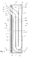
- FIG. 1 shows a first embodiment the device for room ventilation in elevation shown in the side view.
- the device has a fresh air duct 1 with a fresh air inlet 1.1, through which fresh air enters, and a fresh air outlet 1.2, from which the fresh air emerges.
- the fresh air outlet 1.2 is arranged on the inside of the wall, so that the fresh air flows into the room.
- an exhaust duct 2 is provided which has on the inside of the wall an exhaust air inlet 2.1 and on the outside of the wall and thus on the outside of the building an exhaust outlet 2.2.
- the exhaust air flows, as indicated by the arrow 5, in the exhaust duct 2 and exits the room or from the building through the exhaust outlet 2.2, as indicated by the arrow 6, from.
- the exhaust air duct 2 and the fresh air duct 1 extend, as shown in Figure 1, substantially parallel to each other.
- the fresh air duct 1 and the exhaust duct 2 may be formed as tubes and formed from sheet metal.
- both the fresh air duct 1 and the exhaust duct 2 one or more heat exchanger fins 7.1 and 7.2.
- a ventilation flap 15 is provided on the side facing the room of the device for room ventilation.
- the ventilation flap 15 is in Figure 1 in the closed state by the reference numeral 15 'and in the open state by the reference numeral 15''.
- the inventive device for room ventilation can be constructed as a built-in module.
- This has the advantage that it can be industrially prefabricated and installed as a compact component on the site in a corresponding recess on the outer wall quickly and easily can be.
- the installation module has a housing which comprises an inner wall 9, a bottom 12, an outer wall 8 and a cover 13.
- the housing may additionally have an insulation 10 for thermal and / or acoustic insulation. It can be applied to the inner wall 9 of the housing, as shown in Figure 1, the insulation 10 in conjunction with a metal foil or plate 11.
- the first embodiment of the device according to the invention for room ventilation is shown in plan view along the section A-A.
- the side walls 16 and 19 of the housing may additionally be insulated.
- only the side wall 16 of the housing with an insulation 17 and a metal foil or plate 18 is provided.
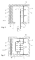
- the first embodiment of the device according to the invention for room ventilation is shown in plan view along the section BB.
- the heat exchanger fins 7.1, which are arranged in the fresh air duct 1, and the heat exchanger fins 7.2, which are arranged in the exhaust air duct 2, are U-shaped and thermally conductive.
- copper and aluminum is suitable because of their high conductivity.
- the U-shaped blades 7.1 and 7.2 are easy to prepare, easily with the partition 14.3, which separates the fresh air duct 1 from the exhaust duct 2, connectable and have a sufficiently high stability.
- the heat exchanger fins 7.1 and 7.2 may instead be formed as extruded webs of aluminum, which are interconnected via a partition plate, which is not shown in the figures. To the length of the exhaust duct 2, this can be equipped with an additional partition 14.2.
- FIG. 4 the first embodiment of the device according to the invention for room ventilation is shown in plan view along the section C-C.
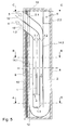
- FIG. 5 a second embodiment of the device for room ventilation in elevation is shown in the side view.
- the second embodiment differs from the first embodiment in that the fresh air duct 1 is arranged in the interior of the exhaust air duct 2.
- the fresh air inlet 1.1 of the fresh air duct 1 is no longer arranged vertically below the exhaust air outlet 2.2, but laterally offset from it.
- the surface of the heat exchanger element is larger than in the first embodiment, whereby in the second embodiment, a higher and thus improved efficiency is achieved.
- FIG 7 the second embodiment of the device for room ventilation according to the invention in plan view along the section BB is shown.
- the heat exchanger fins 7.1 and 7.2 are shorter in the second embodiment than in the first embodiment. Overall, despite the same distance between the heat exchanger fins, a total of more heat exchanger fins can be arranged in the second embodiment than in the first embodiment.
- FIG. 9 a third embodiment of the device for room ventilation in elevation is shown in the side view.
- the third embodiment differs essentially from the first embodiment shown in FIG. 1 in that the fresh air inlet 1.1 and the exhaust air outlet 2.2 are not arranged at right angles to the fresh air outlet 1.2 and exhaust air inlet 2.1, but at the same angle as the fresh air outlet 1.2 and the exhaust air inlet 2.1 exit from the installation module.
- FIG. 10 the third embodiment of the device according to the invention for room ventilation is shown in plan view along the section AA.
- the third embodiment is shown in plan view along section B-B.
- the heat exchanger fins 7.1 and 7.2 are formed in the third embodiment as well as in the first embodiment.
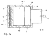
- FIG. 12 the third embodiment is shown in plan view along section C-C.
- the supply of fresh air and the discharge of the used room air takes place in all embodiments in two separate channels 1 and 2, which are integrated in a built-in module.
- the built-in module can be easily installed in the facade. Both the fresh air flow and the exhaust air flow are caused by the static height between the inlet and outlet of the air and by the temperature difference between the interior of the room and the building environment. This has the advantage that no electrical energy is consumed to allow the exchange of air.
- the geometry of the fresh air duct 1, the exhaust duct 2 and the heat exchanger fins 7.1 and 7.2 is chosen so that an optimal, natural air flow is made possible.
- the room ventilation device is designed so that it can be easily cleaned at any time.
- the inner wall 9 is removable.
- the heat exchanger element with the heat exchanger fins 7.1, 7.2 can be removed and cleaned with water.
- the housing 8, 9, 12, 13 can be cleaned with a damp cloth.
- an air filter may be provided which is equipped, for example, with a microfiber-coated element.
- the heat exchanger fins 7.1 and 7.2 may additionally be provided with nubs to filter the incoming fresh air.
- the fresh air duct 1 is coupled to the exhaust air duct 2 through the heat exchanger equipped with heat exchanger fins 7.1 and 7.2.
- the heat exchanger fins 7.1 and 7.2 which may also be referred to as ribs, are welded or soldered onto the separating plate 14.3. As the fresh air flows along the heat exchanger fins 7.1, it heats up and maintains buoyancy. At the same time, warm room air enters the top of the exhaust air inlet 2.1 as exhaust air and is guided downwards via the exhaust air duct 2 past the heat exchanger fins 7.2.
- the housing can be made of wood or metal and is installed in the façade, with a part on the outside and a part on the inside of the building.
- the housing thus forms part of the exterior wall of the room.
- the air inlets 1.1 and 2.1 and the air outlets 1.2 and 2.2 may be made of chromium-nickel steel or aluminum, for example.
- the fresh air inlet 1.1 and the exhaust outlet 2.2 can be sealed to the facade skin.
- adjustable inserts can be provided, with which the fresh air inlet 1.1 and the exhaust outlet 2.2 can be extended, so that they can be adapted to the wall thickness of the building.
- wires can be welded onto the inserts or a correspondingly fine-meshed network can be installed.
- the housing can be equipped with additional heat and sound insulation.
- the front cover 9 has an opening for the fresh air outlet 1.2 and the exhaust air inlet 2.1. With the ventilation flap 15, the opening can be closed if necessary.
- the walls 14.1, 14.2, 14.3 of the fresh air duct 1 and the exhaust duct 2 may be made of sheet metal with a thickness between 0.4 and 1 mm.
- the fresh air duct 1 has a radius of 100 to 130 mm in the lower region.
- the sheets, which together form the fresh air duct 1 and the exhaust duct 2 are folded and produced as standard components in series.
- the heat exchanger fins 7.1 and 7.2 are adapted to the air flow, so that the air resistance is as small as possible. Basically, the smaller the air resistance at the largest possible heat exchanger surface, the higher the efficiency.
Abstract
Description
Die Erfindung betrifft eine Einrichtung und ein Einbaumodul zur Raumlüftung. Mit der Erfindung kann ein beheizter Raum, beispielsweise ein Wohnraum oder ein Büroraum, kontinuierlich mit Frischluft versorgt werden.The invention relates to a device and a built-in module for room ventilation. With the invention, a heated room, such as a living room or office space, can be continuously supplied with fresh air.
Gebäudehüllen, insbesondere Fenster und Wohnungstüren werden, um den Wärmeverlust so gering wie möglich zu halten, immer luftdichter ausgeführt. Bei nicht belüfteten Räumen steigt aufgrund der Dichtigkeit der Fenster und Fassaden die Konzentration an Geruchs- und Schadstoffen sowie die Raumfeuchte und die Sauerstoffkonzentration nimmt entsprechend ab. Dies führt in den Räumen zu einem ungesunden, muffigen Raumklima. Verstärkt wird dieser Effekt durch eine ganztägige Abwesenheit der Bewohner, beispielsweise während der Berufstätigkeit oder den Ferien. Aufgrund der hohen Luftfeuchtigkeit in den Räumen schlägt sich in der kalten Jahreszeit bei schlechter oder nicht ausreichender Lüftung Wasserdampf als Kondensat an den Fenstern und Türen nieder, obwohl eine genügende Wärmedämmung vorhanden ist.Building envelopes, especially windows and apartment doors, to make the heat loss as low as possible, run more airtight. In non-ventilated rooms due to the impermeability of the windows and facades increases the concentration of odors and pollutants and the room humidity and the oxygen concentration decreases accordingly. This leads to an unhealthy, musty room climate in the rooms. This effect is reinforced by a full-day absence of residents, for example, during work or vacation. Due to the high humidity in the rooms, water vapor condenses on the windows and doors as condensate in the cold season with poor or insufficient ventilation, even though there is sufficient thermal insulation.
Um dieses Problem zu beheben, sind aus dem Stand der Technik Flügelbeschläge für Fenster bekannt, mit denen Fenster leicht beabstandet von den Fensterdichtungen verriegelt werden können. Die dadurch gebildete undichte Stelle zwischen Fenster und Fensterdichtung dient dazu den Raum zu lüften.To remedy this problem, prior art wing fittings are known for locking windows slightly spaced from the window seals. The resulting leak between window and window seal serves to ventilate the room.
Des Weiteren sind aus dem Stand der Technik Fensterbeschläge bekannt, mit dem sich das Fenster zu Seite schieben oder kippen lässt, um den Raum zu lüften.Furthermore, from the state of the art window fittings are known with which the window can be pushed to side or tilt to ventilate the room.
Alternativ dazu sind auch zentrale und dezentrale Lüftungsanlagen mit einem elektromechanischen Antrieb und einer Wärmerückgewinnung bekannt. Die beschriebenen Ausführungsformen haben jedoch den Nachteil, dass zum Erzeugen des zum Lüften notwendigen Luftstroms entweder elektrische Energie erforderlich ist oder, insbesondere beim Lüften mit Hilfe der Fenster, ein erheblicher Wärmeverlust entsteht.Alternatively, centralized and decentralized ventilation systems with an electromechanical drive and heat recovery are known. However, the described embodiments have the disadvantage that either electrical energy is required to generate the air flow necessary for ventilation or, in particular when ventilating with the help of the windows, a considerable heat loss is produced.
Eine Aufgabe der Erfindung ist es, eine Einrichtung zur Raumlüftung anzugeben, mit der eine kontinuierliche Frischluftzufuhr bei minimalem Wärmeverlust möglich ist.An object of the invention is to provide a device for room ventilation, with a continuous supply of fresh air with minimal heat loss is possible.
Vorteilhafter Weise erfolgt die Versorgung des Raums mit Frischluft und die Abfuhr der Abluft aus dem Raum passiv, das heisst, ohne dass elektrische Energie verbraucht wird.Advantageously, the supply of the room with fresh air and the removal of the exhaust air from the room is passive, that is, without electrical energy is consumed.
Die Aufgabe wird durch eine Einrichtung zur Raumlüftung mit den Merkmalen gemäß Patentanspruch 1 gelöst. Die Aufgabe wird zudem durch ein Einbaumodul zur Raumlüftung mit den Merkmalen gemäß Patentanspruch 11 gelöst.The object is achieved by a device for room ventilation with the features according to
Die erfindungsgemäße Einrichtung zur Raumlüftung weist einen in eine Wand des Raumes einbaubaren Frischluftkanal auf, über den dem Raum Frischluft zuführbar ist. Die Einrichtung weist zudem einen in die Wand des Raumes einbaubaren Abluftkanal auf, über den Abluft aus dem Raum abführbar ist. Zudem weist die Einrichtung einen Wärmetauscher auf, über welchen der Abluftkanal mit dem Frischluftkanal gekoppelt ist.The device for room ventilation according to the invention has a fresh air duct which can be installed in a wall of the room and via which fresh air can be supplied to the room. The device also has an installable into the wall of the room exhaust duct through which exhaust air from the room can be discharged. In addition, the device has a heat exchanger, via which the exhaust air duct is coupled to the fresh air duct.
Das erfindungsgemäße Einbaumodul zur Raumlüftung, welches in eine Wand des Raumes oder in ein Fenster einbaubar ist, weist ein Gehäuse auf, in dem ein Frischluftkanal vorgesehen ist, über den dem Raum Frischluft zuführbar ist. Im Gehäuse ist des Weiteren ein Abluftkanal vorgesehen, über den Abluft aus dem Raum abführbar ist. Zudem ist im Gehäuse ein Wärmetauscher vorgesehen, über welchen der Abluftkanal mit dem Frischluftkanal gekoppelt ist.The installation module according to the invention for room ventilation, which is installed in a wall of the room or in a window, has a housing in which a fresh air duct is provided, via which the room fresh air can be supplied. In addition, an exhaust duct is provided in the housing, via the exhaust air from the room can be discharged. In addition, a heat exchanger is provided in the housing, via which the exhaust air duct is coupled to the fresh air duct.
Vorteilhafte Weiterbildungen der Erfindung ergeben sich aus den in den abhängigen Patentansprüchen angegebenen Merkmalen.Advantageous developments of the invention will become apparent from the features indicated in the dependent claims.
Bei einer Ausführungsform der erfindungsgemäßen Einrichtung zur Raumlüftung weist der Wärmetauscher wärmeleitfähige Lamellen auf.In one embodiment of the device according to the invention for room ventilation, the heat exchanger on thermally conductive fins.
Bei einer weiteren Ausführungsform der erfindungsgemäßen Einrichtung zur Raumlüftung weisen die Lamellen Aluminium oder Kupfer auf. Dadurch lässt sich der Wärmeaustausch zwischen der Frischluft und der Abluft verbessern.In a further embodiment of the device according to the invention for room ventilation, the slats have aluminum or copper on. As a result, the heat exchange between the fresh air and the exhaust air can be improved.
Bei einer Weiterbildung der erfindungsgemäßen Einrichtung zur Raumlüftung sind die Lamellen U-förmig oder als Stege ausgebildet. Derartige Lamellen sind einfach herstellbar, leicht mit der Wand des Frischluftkanals und des Abluftkanals verbindbar und weisen eine ausreichende Stabilität auf.In a further development of the device according to the invention for room ventilation, the slats are U-shaped or formed as webs. Such slats are easy to prepare, easily connectable to the wall of the fresh air duct and the exhaust duct and have sufficient stability.
Zudem ist es von Vorteil, wenn bei der erfindungsgemäßen Einrichtung zur Raumlüftung die Lamellen im Frischluftkanal und im Abluftkanal vorgesehen sind, weil dadurch der Wärmeaustausch zwischen der Frischluft und der Abluft verbessert werden kann.Moreover, it is advantageous if in the inventive device for room ventilation, the fins are provided in the fresh air duct and the exhaust duct, because thereby the heat exchange between the fresh air and the exhaust air can be improved.
Darüber hinaus kann bei der erfindungsgemäßen Einrichtung zur Raumlüftung der Abluftkanal einen Ablufteinlass und der Frischluftkanal einen Frischluftauslass aufweisen, wobei der Ablufteinlass und der Abluftauslass benachbart angeordnet sind. Dadurch lässt sich der Aufbau und Einbau der Einrichtung zur Raumlüftung kostengünstig und einfach realisieren. Auf der Innenseite der Wand ist lediglich eine Öffnung vorzusehen.In addition, in the inventive device for room ventilation of the exhaust duct, an exhaust air inlet and the fresh air duct having a fresh air outlet, wherein the exhaust air inlet and the exhaust air outlet are arranged adjacent. As a result, the construction and installation of the device for room ventilation can be realized inexpensively and easily. On the inside of the wall is only an opening provided.
Ferner wird in einer Weiterbildung vorgeschlagen, dass die erfindungsgemäße Einrichtung zur Raumlüftung eine Lüftungsklappe aufweist, mittels welcher der Frischluftkanal und der Abluftkanal verschließbar sind. Dadurch lässt sich sicherstellen, dass eine Lüftung des Raumes nur dann erfolgt, wenn diese auch wirklich gewünscht ist.Furthermore, it is proposed in a development that the inventive device for room ventilation has a ventilation flap, by means of which the fresh air duct and the exhaust duct are closed. This ensures that the room is ventilated only when it is really desired.
Zudem kann die erfindungsgemäße Einrichtung zur Raumlüftung einen Luftfilter aufweisen, welcher im Frischluftkanal angeordnet ist. Dies hat den Vorteil, dass die in den Raum strömende Frischluft vorab von Staubpartikeln gereinigt und dadurch die Verschmutzung des Raumes durch Staub reduziert wird.In addition, the inventive device for room ventilation may have an air filter which is arranged in the fresh air duct. This has the advantage that the fresh air flowing into the room in advance cleaned of dust particles, thereby reducing the pollution of the room by dust is reduced.
Bei der erfindungsgemäßen Einrichtung zur Raumlüftung kann der Luftfilter mit einem mikrofaserbeschichteten Element ausgestattet sein. Dieses hat eine ausreichend hohe Filterwirkung und lässt sich jederzeit reinigen oder durch ein Neues ersetzen.In the inventive device for room ventilation, the air filter may be equipped with a microfiber-coated element. This has a sufficiently high filtration effect and can be cleaned at any time or replaced by a new one.
Bei einer Weiterbildung der erfindungsgemäßen Einrichtung zur Raumlüftung ist der Frischluftkanal im Inneren des Abluftkanals angeordnet. Dadurch lässt sich die Fläche, über die der Wärmeaustausch zwischen Frischluft und Abluft erfolgt, vergrößern, ohne dass die gesamte Einrichtung zur Raumlüftung vergrößert werden muss.In a further development of the device according to the invention for room ventilation, the fresh air duct is arranged in the interior of the exhaust air duct. As a result, the area over which the heat exchange between fresh air and exhaust air takes place can be increased without the entire room ventilation device having to be enlarged.
Schließlich kann bei dem erfindungsgemäßen Einbaumodul zur Raumlüftung das Gehäuse eine Wärmedämmschicht aufweisen. Dadurch lässt sich sicherstellen, dass das Einbaumodul keine Kältebrücke bildet. Mit Hilfe einer Schalldämmschicht kann zusätzlich auch eine ausreichende Schalldämmung erreicht werden.Finally, in the case of the inventive installation module for room ventilation, the housing may have a thermal barrier coating. This ensures that the built-in module does not form a cold bridge. With the help of a sound insulation layer can also be achieved a sufficient sound insulation.
Im Folgenden wird die Erfindung mit mehreren Ausführungsbeispielen anhand von 12 Figuren weiter erläutert.
Figur 1- zeigt eine erste Ausführungsform der erfindungsgemäßen Vorrichtung zur Raumlüftung in der Seitenansicht.
Figur 2- zeigt die erste Ausführungsform der erfindungsgemäßen Vorrichtung zur Raumlüftung in einem ersten Querschnitt.
Figur 3- zeigt die erste Ausführungsform der erfindungsgemäßen Vorrichtung zur Raumlüftung in einem zweiten Querschnitt.
Figur 4- zeigt die erste Ausführungsform der erfindungsgemäßen Vorrichtung zur Raumlüftung in einem dritten Querschnitt.
Figur 5- zeigt eine zweite Ausführungsform der erfindungsgemäßen Vorrichtung zur Raumlüftung in der Seitenansicht.
Figur 6- zeigt die zweite Ausführungsform der erfindungsgemäßen Vorrichtung zur Raumlüftung in einem ersten Querschnitt.
- Figur 7
- zeigt die zweite Ausführungsform der erfindungsgemäßen Vorrichtung zur Raumlüftung in einem zweiten Querschnitt.
Figur 8- zeigt die zweite Ausführungsform der erfindungsgemäßen Vorrichtung zur Raumlüftung in einem dritten Querschnitt.
Figur 9- zeigt eine dritte Ausführungsform der erfindungsgemäßen Vorrichtung zur Raumlüftung in der Seitenansicht.
Figur 10- zeigt die dritte Ausführungsform der erfindungsgemäßen Vorrichtung zur Raumlüftung in einem ersten Querschnitt.
Figur 11- zeigt die dritte Ausführungsform der erfindungsgemäßen Vorrichtung zur Raumlüftung in einem zweiten Querschnitt.
Figur 12- zeigt die dritte Ausführungsform der erfindungsgemäßen Vorrichtung zur Raumlüftung in einem dritten Querschnitt.
- FIG. 1
- shows a first embodiment of the device according to the invention for room ventilation in the side view.
- FIG. 2
- shows the first embodiment of the device according to the invention for room ventilation in a first cross section.
- FIG. 3
- shows the first embodiment of the device according to the invention for room ventilation in a second cross section.
- FIG. 4
- shows the first embodiment of the inventive device for room ventilation in a third cross section.
- FIG. 5
- shows a second embodiment of the inventive device for room ventilation in the side view.
- FIG. 6
- shows the second embodiment of the device according to the invention for room ventilation in a first cross section.
- FIG. 7
- shows the second embodiment of the device according to the invention for room ventilation in a second cross section.
- FIG. 8
- shows the second embodiment of the inventive device for room ventilation in a third cross section.
- FIG. 9
- shows a third embodiment of the device according to the invention for room ventilation in the side view.
- FIG. 10
- shows the third embodiment of the device according to the invention for room ventilation in a first cross section.
- FIG. 11
- shows the third embodiment of the device according to the invention for room ventilation in a second cross section.
- FIG. 12
- shows the third embodiment of the device according to the invention for room ventilation in a third cross section.
Im Folgenden wird die Kombination aus Frischluftkanal, Abluftkanal und Wärmetauscher als Einrichtung zur Raumlüftung bezeichnet. Werden diese Komponenten zu einer einzigen Einbaueinheit zusammengefügt, so wird im Folgenden von einem Einbaumodul zur Raumlüftung gesprochen. Bei der Einrichtung zur Raumlüftung ist es möglich, dass deren einzelne Komponenten erst vor Ort zusammengefügt und eingebaut werden. Die Einrichtung zur Raumlüftung kann aber auch als Einbaumodul realisiert werden.In the following, the combination of fresh air duct, exhaust duct and heat exchanger is referred to as a room ventilation device. If these components are combined to form a single installation unit, the following is spoken of by a built-in module for room ventilation. With the device for room ventilation, it is possible that their individual components are assembled and installed on site. The device for room ventilation can also be implemented as a built-in module.
Im Folgenden wird eine erste Ausführungsform der Erfindung beschrieben. In Figur 1 ist eine erste Ausführungsform der Vorrichtung zur Raumlüftung im Aufriss in der Seitenansicht gezeigt. Die Vorrichtung weist einen Frischluftkanal 1 mit einem Frischlufteinlass 1.1, durch den Frischluft eintritt, und einen Frischluftauslass 1.2 auf, aus dem die Frischluft austritt. Der Frischluftauslass 1.2 ist auf der Innenseite der Wand angeordnet, so dass die Frischluft in den Raum strömt. Zudem ist ein Abluftkanal 2 vorgesehen, der auf der Innenseite der Wand einen Ablufteinlass 2.1 und auf der Aussenseite der Wand und damit auf der Gebäudeaußenseite einen Abluftauslass 2.2 aufweist. Die Abluft strömt, wie durch den Pfeil 5 gekennzeichnet, in den Abluftkanal 2 und tritt aus dem Raum beziehungsweise aus dem Gebäude durch den Abluftauslass 2.2, wie durch den Pfeil 6 gekennzeichnet, aus. Der Abluftkanal 2 und der Frischluftkanal 1 verlaufen, wie in Figur 1 gezeigt, im Wesentlichen parallel zueinander. Der Frischluftkanal 1 und der Abluftkanal 2 können als Rohre ausgebildet und aus Blech geformt sein. Um den Wärmeaustausch zwischen der Abluft und der Frischluft zu gewährleisten, weist sowohl der Frischluftkanal 1 als auch der Abluftkanal 2 eine oder mehrere Wärmetauscherlamellen 7.1 und 7.2 auf. Auf der dem Raum zugewandten Seite der Vorrichtung zur Raumlüftung ist eine Lüftungsklappe 15 vorgesehen. Die Lüftungsklappe 15 ist in Figur 1 in geschlossenem Zustand durch das Bezugszeichen 15' und im offenen Zustand durch das Bezugszeichen 15'' gekennzeichnet.Hereinafter, a first embodiment of the invention will be described. FIG. 1 shows a first embodiment the device for room ventilation in elevation shown in the side view. The device has a
Die erfindungsgemäße Vorrichtung zur Raumlüftung kann als Einbaumodul aufgebaut sein. Dies hat den Vorteil, dass es industriell vorgefertigt werden kann und als kompaktes Bauelement auf der Baustelle in eine entsprechende Aussparung an der Außenwand einfach und schnell eingebaut werden kann. Das Einbaumodul weist dazu ein Gehäuse, das eine Innenwand 9, einen Boden 12, eine Außenwand 8 und einen Deckel 13 umfasst, auf. Das Gehäuse kann zusätzlich eine Isolierung 10 zur Wärme- und/oder Schalldämmung aufweisen. Dabei kann auf die Innenwand 9 des Gehäuses, wie in Figur 1 gezeigt, die Isolierung 10 in Verbindung mit einer Metallfolie oder Platte 11 aufgebracht sein.The inventive device for room ventilation can be constructed as a built-in module. This has the advantage that it can be industrially prefabricated and installed as a compact component on the site in a corresponding recess on the outer wall quickly and easily can be. For this purpose, the installation module has a housing which comprises an
In Figur 2 ist die erste Ausführungsform der erfindungsgemäßen Vorrichtung zur Raumlüftung in der Draufsicht entlang des Schnitts A-A dargestellt. Die Seitenwände 16 und 19 des Gehäuses können zusätzlich isoliert sein. Bei der in Figur 2 gezeigten Ausführungsform ist lediglich die Seitenwand 16 des Gehäuses mit einer Isolierung 17 und einer Metallfolie oder Platte 18 versehen.In FIG. 2, the first embodiment of the device according to the invention for room ventilation is shown in plan view along the section A-A. The
In Figur 3 ist die erste Ausführungsform der erfindungsgemäßen Vorrichtung zur Raumlüftung in der Draufsicht entlang des Schnitts B-B dargestellt. Die Wärmetauscherlamellen 7.1, welche im Frischluftkanal 1 angeordnet sind, und die Wärmetauscherlamellen 7.2, welche im Abluftkanal 2 angeordnet sind, sind U-förmig geformt und wärmeleitfähig. Hierfür eignet sich insbesondere Kupfer und Aluminium aufgrund ihrer hohen Leitfähigkeit. Die U-förmigen Lamellen 7.1 und 7.2 sind einfach herstellbar, leicht mit der Trennwand 14.3, welche den Frischluftkanal 1 vom Abluftkanal 2 trennt, verbindbar und weisen eine ausreichend hohe Stabilität auf. Die Wärmetauscherlamellen 7.1 und 7.2 können statt dessen auch als stranggepresste Stege aus Aluminium ausgebildet sein, die über ein Trennblech miteinander verbunden sind, was in den Figuren jedoch nicht dargestellt ist. Um die Länge des Abluftkanals 2 zu vergrößern, kann dieser mit einer zusätzlichen Trennwand 14.2 ausgestattet sein.In FIG. 3, the first embodiment of the device according to the invention for room ventilation is shown in plan view along the section BB. The heat exchanger fins 7.1, which are arranged in the
In Figur 4 ist die erste Ausführungsform der erfindungsgemäßen Vorrichtung zur Raumlüftung in der Draufsicht entlang des Schnitts C-C dargestellt.In FIG. 4, the first embodiment of the device according to the invention for room ventilation is shown in plan view along the section C-C.
Im Folgenden wird eine zweite Ausführungsform der Erfindung beschrieben. In Figur 5 ist eine zweite Ausführungsform der Vorrichtung zur Raumlüftung im Aufriss in der Seitenansicht gezeigt. Im Wesentlichen unterscheidet sich die zweite Ausführungsform von der ersten Ausführungsform dadurch, dass der Frischluftkanal 1 im Inneren des Abluftkanals 2 angeordnet ist. Dies führt dazu, dass der Frischlufteinlass 1.1 des Frischluftkanals 1 nicht mehr senkrecht unterhalb des Abluftauslasses 2.2 angeordnet ist, sondern seitlich versetzt dazu.Hereinafter, a second embodiment of the invention will be described. In Figure 5, a second embodiment of the device for room ventilation in elevation is shown in the side view. In essence, the second embodiment differs from the first embodiment in that the
Bei der zweiten Ausführungsform ist die Oberfläche des Wärmetauscherelements grösser als bei der ersten Ausführungsform, wodurch bei der zweiten Ausführungsform ein höherer und damit verbesserter Wirkungsgrad erzielt wird.In the second embodiment, the surface of the heat exchanger element is larger than in the first embodiment, whereby in the second embodiment, a higher and thus improved efficiency is achieved.
In Figur 6 ist die zweite Ausführungsform der erfindungsgemäßen Vorrichtung zur Raumlüftung in der Draufsicht entlang des Schnitts A-A gezeigt.In Figure 6, the second embodiment of the device according to the invention for room ventilation in plan view along the section A-A is shown.
In Figur 7 ist die zweite Ausführungsform der erfindungsgemäßen Vorrichtung zur Raumlüftung in der Draufsicht entlang des Schnitts B-B gezeigt. Die Wärmetauscherlamellen 7.1 und 7.2 sind bei der zweiten Ausführungsform kürzer als bei der ersten Ausführungsform. Insgesamt lassen sich bei der zweiten Ausführungsform trotz gleichem Abstand zwischen den Wärmetauscherlamellen insgesamt mehr Wärmetauscherlamellen anordnen als bei der ersten Ausführungsform.In Figure 7, the second embodiment of the device for room ventilation according to the invention in plan view along the section BB is shown. The heat exchanger fins 7.1 and 7.2 are shorter in the second embodiment than in the first embodiment. Overall, despite the same distance between the heat exchanger fins, a total of more heat exchanger fins can be arranged in the second embodiment than in the first embodiment.
In Figur 8 ist die zweite Ausführungsform der erfindungsgemäßen Vorrichtung zur Raumlüftung in der Draufsicht entlang des Schnitts C-C dargestellt.In Figure 8, the second embodiment of the inventive device for room ventilation in plan view along the section C-C is shown.
Im Folgenden wird eine dritte Ausführungsform der Erfindung beschrieben. In Figur 9 ist eine dritte Ausführungsform der Vorrichtung zur Raumlüftung im Aufriss in der Seitenansicht gezeigt. Die dritte Ausführungsform unterscheidet sich im Wesentlichen von der in Figur 1 gezeigten ersten Ausführungsform dadurch, dass der Frischlufteinlass 1.1 und der Abluftauslass 2.2 nicht im rechten Winkel zum Frischluftauslass 1.2 und Ablufteinlass 2.1 angeordnet sind, sondern im gleichen Winkel wie der Frischluftauslass 1.2 und der Ablufteinlass 2.1 aus dem Einbaumodul austreten.Hereinafter, a third embodiment of the invention will be described. In Figure 9, a third embodiment of the device for room ventilation in elevation is shown in the side view. The third embodiment differs essentially from the first embodiment shown in FIG. 1 in that the fresh air inlet 1.1 and the exhaust air outlet 2.2 are not arranged at right angles to the fresh air outlet 1.2 and exhaust air inlet 2.1, but at the same angle as the fresh air outlet 1.2 and the exhaust air inlet 2.1 exit from the installation module.
Welche der Ausführungsformen bevorzugt wird, hängt von den technischen Randbedingungen und den gebäudlichen Gegebenheiten ab.Which of the embodiments is preferred depends on the technical boundary conditions and the building conditions.
In Figur 10 ist die dritte Ausführungsform der erfindungsgemäßen Vorrichtung zur Raumlüftung in der Draufsicht entlang des Schnitts A-A gezeigt.In FIG. 10, the third embodiment of the device according to the invention for room ventilation is shown in plan view along the section AA.
In Figur 11 ist die dritte Ausführungsform in der Draufsicht entlang des Schnitts B-B gezeigt. Die Wärmetauscherlamellen 7.1 und 7.2 sind bei der dritten Ausführungsform genauso geformt wie bei der ersten Ausführungsform.In Figure 11, the third embodiment is shown in plan view along section B-B. The heat exchanger fins 7.1 and 7.2 are formed in the third embodiment as well as in the first embodiment.
In der Figur 12 schließlich ist die dritte Ausführungsform in der Draufsicht entlang des Schnitts C-C gezeigt.Finally, in FIG. 12, the third embodiment is shown in plan view along section C-C.
Die Zuführung der Frischluft und die Abführung der verbrauchten Raumluft erfolgt bei allen Ausführungsformen in zwei getrennten Kanälen 1 und 2, die in ein Einbaumodul integriert sind. Das Einbaumodul lässt sich problemlos in die Fassade einbauen. Sowohl der Frischluftstrom als auch der Abluftstrom entstehen durch die statische Höhe zwischen Ein- und Austritt der Luft sowie durch den Temperaturunterschied zwischen dem Rauminneren und der Gebäudeumgebung. Dies hat den Vorteil, dass keine elektrische Energie verbraucht wird, um den Luftaustausch zu ermöglichen.The supply of fresh air and the discharge of the used room air takes place in all embodiments in two
Die Geometrie des Frischluftkanals 1, des Abluftkanals 2 und der Wärmetauscherlamellen 7.1 und 7.2 ist so gewählt, dass eine optimale, natürliche Luftströmung ermöglicht wird.The geometry of the
Die Vorrichtung zur Raumlüftung ist so konstruiert, dass sie jederzeit problemlos gereinigt werden kann. Die Innenwand 9 ist dazu abnehmbar. Das Wärmetauscherelement mit den Wärmetauscherlamellen 7.1, 7.2 kann herausgenommen und mit Wasser gereinigt werden. Ebenso kann das Gehäuse 8, 9, 12, 13 mit einem feuchten Tuch gereinigt werden.The room ventilation device is designed so that it can be easily cleaned at any time. The
Im Inneren des Frischluftkanals 1 kann ein Luftfilter vorgesehen sein, der beispielsweise mit einem mikrofaserbeschichteten Element bestückt ist. Dadurch kann die in den Raum transportierte Frischluft bereits vorab gereinigt werden.In the interior of the
Die Wärmetauscherlamellen 7.1 und 7.2 können zusätzlich mit Noppen versehen sein, um die einströmende Frischluft zu filtern.The heat exchanger fins 7.1 and 7.2 may additionally be provided with nubs to filter the incoming fresh air.
Mit Hilfe der erfindungsgemäßen Vorrichtung zur Raumlüftung wird ein kontinuierlicher Luftaustausch mit Wärmerückgewinnung ermöglicht.With the help of the device according to the invention for room ventilation, a continuous exchange of air with heat recovery is possible.
Kalte Frischluft tritt durch den Frischlufteinlass 1.1 in den Frischluftkanal 1 ein, wird dort nach oben geleitet und über den Frischluftauslass 1.2 in den Raum geführt. Der Frischluftkanal 1 ist durch den mit Wärmetauscherlamellen 7.1 und 7.2 ausgestatteten Wärmetauscher mit dem Abluftkanal 2 gekoppelt. Die Wärmetauscherlamellen 7.1 und 7.2, welche auch als Rippen bezeichnet werden können, sind auf das Trennblech 14.3 aufgeschweißt oder aufgelötet. Während die Frischluft an den Wärmetauscherlamellen 7.1 entlang strömt, erwärmt sie sich und erhält so den Auftrieb. Gleichzeitig tritt warme Raumluft als Abluft oben in den Ablufteinlass 2.1 ein und wird über den Abluftkanal 2 an den Wärmetauscherlamellen 7.2 vorbei nach unten geführt. Während die Abluft an den Wärmetauscherlamellen 7.2 vorbei strömt, gibt sie Wärmeenergie an die Lamellen 7.2 ab und kühlt sich dabei weiter ab. Die nun kühlere Abluft wird im unteren Teil des Abluftkanals 2 umgeleitet, wieder nach oben geführt und tritt durch den Abluftauslass 2.2 aus dem Raum beziehungsweise aus dem Gebäude aus.Cold fresh air enters through the fresh air inlet 1.1 in the
Das Gehäuse kann aus Holz oder Metall bestehen und wird so in die Fassade eingebaut, dass sich ein Teil auf der Außenseite und ein Teil auf der Innenseite des Gebäudes befindet, Das Gehäuse bildet somit einen Teil der Außenwand des Raumes. Beim Einbaumodul sind im Gehäuse geformte Füllstücke in Holz mit Metallverkleidung und eine Schalldämmeinlage mit Metalloberfläche fest eingebaut. Die Lufteinlässe 1.1 und 2.1 und die Luftauslässe 1.2 und 2.2 können beispielsweise aus Chrom-Nickel-Stahl oder Aluminium hergestellt sein. Der Frischlufteinlass 1.1 und der Abluftauslass 2.2 können an der Fassadenhaut abgedichtet werden. Zusätzlich können verstellbare Einsätze vorgesehen sein, mit denen der Frischlufteinlass 1.1 und der Abluftauslass 2.2 verlängerbar sind, so dass sie dadurch an die Wandstärke des Gebäudes angepasst werden können.The housing can be made of wood or metal and is installed in the façade, with a part on the outside and a part on the inside of the building. The housing thus forms part of the exterior wall of the room. In the built-in module molded in the housing fills in wood with metal cladding and a Schalldämmeinlage with metal surface are firmly installed. The air inlets 1.1 and 2.1 and the air outlets 1.2 and 2.2 may be made of chromium-nickel steel or aluminum, for example. The fresh air inlet 1.1 and the exhaust outlet 2.2 can be sealed to the facade skin. In addition, adjustable inserts can be provided, with which the fresh air inlet 1.1 and the exhaust outlet 2.2 can be extended, so that they can be adapted to the wall thickness of the building.
Um zu verhindern, dass Insekten in den Frischluftkanal 1 und den Abluftkanal 2 gelangen, können Drähte auf die Einsätze aufgeschweißt werden oder ein entsprechend feinmaschiges Netz eingebaut sein.In order to prevent insects from entering the
Das Gehäuse kann je nach Einbauart und Anforderung mit zusätzlichen Aufdoppelungen wärme- und schalltechnisch ausgerüstet werden.Depending on the type of installation and the requirement, the housing can be equipped with additional heat and sound insulation.
Die Innenwand 9, die auch als Frontdeckel bezeichnet wird, bestehend aus der Platte 9, der Isolierung 10 und der Platte 11, ist abnehmbar und kann als isolierte Sandwichplatte in Holz oder Metall ausgeführt sein. Im oberen Bereich weist der Frontdeckel 9 eine Öffnung für den Frischluftauslass 1.2 und den Ablufteinlass 2.1 auf. Mit der Lüftungsklappe 15 kann die Öffnung bei Bedarf geschlossen werden.The
Die Wände 14.1, 14.2, 14.3 des Frischluftkanals 1 und des Abluftkanals 2 können aus Metallblech mit einer Stärke zwischen 0,4 und 1 mm ausgeführt sein. Der Frischluftkanal 1 weist in einer Ausführungsform im unteren Bereich einen Radius von 100 bis 130 mm auf. Die Bleche, die zusammen den Frischluftkanal 1 und den Abluftkanal 2 bilden, sind abgekantet und als Standardbauteile in Serie herstellbar. Die Wärmetauscherlamellen 7.1 und 7.2 sind an die Luftströmung angepasst, sodass der Luftwiderstand möglichst klein wird. Grundsätzlich gilt, je kleiner der Luftwiderstand bei möglichst grosser Wärmetauscherfläche ist, desto höher ist der Wirkungsgrad.The walls 14.1, 14.2, 14.3 of the
Mit Hilfe der Vorrichtung zur Raumlüftung wird neben der Lüftung des Raumes auch dafür gesorgt, dass der Wasserdampfdruck im Raum an die Umgebung ausserhalb des Raums angepasst wird.With the help of the device for room ventilation in addition to the ventilation of the room is also ensured that the water vapor pressure in the room is adapted to the environment outside the room.
Die vorhergehende Beschreibung der Ausführungsbeispiele gemäß der vorliegenden Erfindung dient nur zu illustrativen Zwecken und nicht zum Zwecke der Beschränkung der Erfindung. Im Rahmen der Erfindung sind verschiedene Änderungen und Modifikationen möglich, ohne den Umfang der Erfindung sowie ihre Äquivalente zu verlassen.The foregoing description of the embodiments according to the present invention is for illustrative purposes only, and not for the purpose of limiting the invention. Various changes and modifications are possible within the scope of the invention without departing from the scope of the invention and its equivalents.
Bezugszeichenliste
- 1
- Frischluftkanal
- 1.1
- Frischlufteinlass
- 1.2
- Frischluftauslass
- 2
- Abluftkanal
- 2.1
- Ablufteinlass
- 2.2
- Abluftauslass
- 3
- Strömungsrichtung der Frischluft
- 4
- Strömungsrichtung der Frischluft
- 5
- Strömungsrichtung der Abluft
- 6
- Strömungsrichtung der Abluft
- 7.1
- Wärmetauscherlamellen im Frischluftkanal
- 7.2
- Wärmetauscherlamellen im Abluftkanal
- 8
- Aussenwand
- 9
- erste Innenwand
- 10
- Isolierung
- 11
- zweite Innenwand
- 12
- Boden
- 13
- Deckel
- 14.1
- Seitenblech
- 14.2
- Seitenblech
- 14.3
- Seitenblech
- 15'
- Lüftungsklappe in Stellung geschlossen
- 15''
- Lüftungsklappe in Stellung offen
- 16
- erste Seitenwand
- 17
- Isolierung
- 18
- zweite Seitenwand
- 19
- Seitenwand
- 1
- Fresh air duct
- 1.1
- Fresh air inlet
- 1.2
- fresh air outlet
- 2
- exhaust duct
- 2.1
- air inlet
- 2.2
- exhaust outlet
- 3
- Flow direction of the fresh air
- 4
- Flow direction of the fresh air
- 5
- Flow direction of the exhaust air
- 6
- Flow direction of the exhaust air
- 7.1
- Heat exchanger fins in the fresh air duct
- 7.2
- Heat exchanger fins in the exhaust duct
- 8th
- outer wall
- 9
- first inner wall
- 10
- insulation
- 11
- second inner wall
- 12
- ground
- 13
- cover
- 14.1
- Page sheet
- 14.2
- Page sheet
- 14.3
- Page sheet
- 15 '
- Ventilation flap closed in position
- 15 ''
- Ventilation flap in open position
- 16
- first sidewall
- 17
- insulation
- 18
- second side wall
- 19
- Side wall
Claims (12)
bei dem das Gehäuse (8, 9, 12, 13) eine Wärmedämmschicht und/oder eine Schalldämmschicht (10, 17) aufweist.Installation module according to claim 11,
in which the housing (8, 9, 12, 13) has a thermal insulation layer and / or a sound insulation layer (10, 17).
Applications Claiming Priority (1)
| Application Number | Priority Date | Filing Date | Title |
|---|---|---|---|
| CH01295/04A CH696891A5 (en) | 2004-08-02 | 2004-08-02 | Device for ventilation and built-in module for ventilation |
Publications (2)
| Publication Number | Publication Date |
|---|---|
| EP1624258A2 true EP1624258A2 (en) | 2006-02-08 |
| EP1624258A3 EP1624258A3 (en) | 2006-12-20 |
Family
ID=35219558
Family Applications (1)
| Application Number | Title | Priority Date | Filing Date |
|---|---|---|---|
| EP05405276A Withdrawn EP1624258A3 (en) | 2004-08-02 | 2005-03-30 | Apparatus for room ventilation and assembly modul for room ventilation |
Country Status (2)
| Country | Link |
|---|---|
| EP (1) | EP1624258A3 (en) |
| CH (1) | CH696891A5 (en) |
Cited By (11)
| Publication number | Priority date | Publication date | Assignee | Title |
|---|---|---|---|---|
| EP1832818A2 (en) * | 2006-03-06 | 2007-09-12 | STIEBEL ELTRON GmbH & Co. KG | Ventilation system |
| FR2925953A1 (en) * | 2007-12-28 | 2009-07-03 | Atlantic Climatisation & Venti | Double flow heat exchanger box for replacing air in toilet of apartment building, has fresh air inlet and polluted air evacuation departure located in rear wall of box opposite to front wall free from fresh air outlet/extraction inlet |
| FR2939873A1 (en) * | 2008-12-15 | 2010-06-18 | Pierre Vironneau | INSTALLATION FOR RENEWING THE AIR OF A WORKPIECE FROM A DOUBLE FLOW THERMAL EXCHANGER HAVING INSIDE |
| FR2944340A1 (en) * | 2009-04-14 | 2010-10-15 | Iosis Concept | Ventilation installation for use in apartment house, has heat exchangers respectively arranged at air intake branch and air exit branch of air inlet duct and air ventilation duct to form heat exchange branches |
| EP2378216A3 (en) * | 2010-04-13 | 2013-07-24 | Erwin Grohmann | Ventilation device |
| FR3014172A1 (en) * | 2013-12-02 | 2015-06-05 | Scabe Innovations | AERAULIC SHEATH FOR AIR CONDITIONING IN A FARM BUILDING AND LIVESTOCK BUILDING PROVIDED WITH SUCH AN AERAULIC SHEATH |
| DE202015102213U1 (en) | 2015-04-30 | 2015-07-10 | Tobias Becker | Adaptable facade element |
| EP3214254A1 (en) * | 2016-03-03 | 2017-09-06 | Skaala Production Oy | Ventilation device, ventilation window and heat exchanger |
| EP3214381A1 (en) * | 2016-03-03 | 2017-09-06 | Skaala Production Oy | Ventilation device and ventilation method |
| CN109386898A (en) * | 2017-08-04 | 2019-02-26 | 广东美的制冷设备有限公司 | Air treatment module and air conditioner |
| EP4223109A1 (en) * | 2022-02-01 | 2023-08-09 | Schauer Agrotronic GmbH | Power generation system for utilizing waste heat |
Citations (8)
| Publication number | Priority date | Publication date | Assignee | Title |
|---|---|---|---|---|
| DE3118053A1 (en) * | 1981-05-07 | 1983-01-05 | Günter Dipl.-Architekt 6096 Raunheim Hack | Ventilating device in the window wall of buildings |
| DE3239034A1 (en) * | 1982-08-18 | 1984-03-01 | Christoph 1000 Berlin Adam | Room ventilator with recuperative heat exchanger |
| DE3409586A1 (en) * | 1983-03-16 | 1984-10-18 | Norcros Investments Ltd., Reading, Berkshire | FAN |
| GB2192451A (en) * | 1986-05-21 | 1988-01-13 | Paul Whyatt | Doors with heat exchanging ventilators |
| DE3802583A1 (en) * | 1988-01-29 | 1989-08-10 | Wetzel Alfred | Ventilating apparatus for windows and/or French windows for the recuperative ventilating and venting of lounges (recreation rooms) |
| DE29613438U1 (en) * | 1995-08-16 | 1996-09-19 | Haeusler Peter | Ventilation device for supplying and removing air in a building |
| DE10310435B3 (en) * | 2003-02-05 | 2004-06-03 | Helsa-Werke Helmut Sandler Gmbh & Co. Kg | Filter element, useful e.g. as air filter for retaining soot, dust, pollen and insects, is made from 2 or more air-permeable supports, each coated on opposite sides with nano- and/or micro-fibers of opposite electrical polarity |
| EP1486637A2 (en) * | 2003-06-12 | 2004-12-15 | Lidartech Co., Ltd. | Window having a ventilation equipment |
-
2004
- 2004-08-02 CH CH01295/04A patent/CH696891A5/en not_active IP Right Cessation
-
2005
- 2005-03-30 EP EP05405276A patent/EP1624258A3/en not_active Withdrawn
Patent Citations (8)
| Publication number | Priority date | Publication date | Assignee | Title |
|---|---|---|---|---|
| DE3118053A1 (en) * | 1981-05-07 | 1983-01-05 | Günter Dipl.-Architekt 6096 Raunheim Hack | Ventilating device in the window wall of buildings |
| DE3239034A1 (en) * | 1982-08-18 | 1984-03-01 | Christoph 1000 Berlin Adam | Room ventilator with recuperative heat exchanger |
| DE3409586A1 (en) * | 1983-03-16 | 1984-10-18 | Norcros Investments Ltd., Reading, Berkshire | FAN |
| GB2192451A (en) * | 1986-05-21 | 1988-01-13 | Paul Whyatt | Doors with heat exchanging ventilators |
| DE3802583A1 (en) * | 1988-01-29 | 1989-08-10 | Wetzel Alfred | Ventilating apparatus for windows and/or French windows for the recuperative ventilating and venting of lounges (recreation rooms) |
| DE29613438U1 (en) * | 1995-08-16 | 1996-09-19 | Haeusler Peter | Ventilation device for supplying and removing air in a building |
| DE10310435B3 (en) * | 2003-02-05 | 2004-06-03 | Helsa-Werke Helmut Sandler Gmbh & Co. Kg | Filter element, useful e.g. as air filter for retaining soot, dust, pollen and insects, is made from 2 or more air-permeable supports, each coated on opposite sides with nano- and/or micro-fibers of opposite electrical polarity |
| EP1486637A2 (en) * | 2003-06-12 | 2004-12-15 | Lidartech Co., Ltd. | Window having a ventilation equipment |
Cited By (14)
| Publication number | Priority date | Publication date | Assignee | Title |
|---|---|---|---|---|
| EP1832818A2 (en) * | 2006-03-06 | 2007-09-12 | STIEBEL ELTRON GmbH & Co. KG | Ventilation system |
| EP1832818A3 (en) * | 2006-03-06 | 2009-08-19 | STIEBEL ELTRON GmbH & Co. KG | Ventilation system |
| FR2925953A1 (en) * | 2007-12-28 | 2009-07-03 | Atlantic Climatisation & Venti | Double flow heat exchanger box for replacing air in toilet of apartment building, has fresh air inlet and polluted air evacuation departure located in rear wall of box opposite to front wall free from fresh air outlet/extraction inlet |
| FR2939873A1 (en) * | 2008-12-15 | 2010-06-18 | Pierre Vironneau | INSTALLATION FOR RENEWING THE AIR OF A WORKPIECE FROM A DOUBLE FLOW THERMAL EXCHANGER HAVING INSIDE |
| WO2010076472A1 (en) * | 2008-12-15 | 2010-07-08 | Pierre Vironneau | Equipment for renewing air in a plurality of rooms by means of a dual flow heat exchanger provided in each room |
| FR2944340A1 (en) * | 2009-04-14 | 2010-10-15 | Iosis Concept | Ventilation installation for use in apartment house, has heat exchangers respectively arranged at air intake branch and air exit branch of air inlet duct and air ventilation duct to form heat exchange branches |
| EP2378216A3 (en) * | 2010-04-13 | 2013-07-24 | Erwin Grohmann | Ventilation device |
| FR3014172A1 (en) * | 2013-12-02 | 2015-06-05 | Scabe Innovations | AERAULIC SHEATH FOR AIR CONDITIONING IN A FARM BUILDING AND LIVESTOCK BUILDING PROVIDED WITH SUCH AN AERAULIC SHEATH |
| DE202015102213U1 (en) | 2015-04-30 | 2015-07-10 | Tobias Becker | Adaptable facade element |
| WO2016173585A1 (en) | 2015-04-30 | 2016-11-03 | Tobias Becker | Double-walled façade element having a variable-volume air cushion |
| EP3214254A1 (en) * | 2016-03-03 | 2017-09-06 | Skaala Production Oy | Ventilation device, ventilation window and heat exchanger |
| EP3214381A1 (en) * | 2016-03-03 | 2017-09-06 | Skaala Production Oy | Ventilation device and ventilation method |
| CN109386898A (en) * | 2017-08-04 | 2019-02-26 | 广东美的制冷设备有限公司 | Air treatment module and air conditioner |
| EP4223109A1 (en) * | 2022-02-01 | 2023-08-09 | Schauer Agrotronic GmbH | Power generation system for utilizing waste heat |
Also Published As
| Publication number | Publication date |
|---|---|
| CH696891A5 (en) | 2008-01-15 |
| EP1624258A3 (en) | 2006-12-20 |
Similar Documents
| Publication | Publication Date | Title |
|---|---|---|
| EP1624258A2 (en) | Apparatus for room ventilation and assembly modul for room ventilation | |
| EP2594725B1 (en) | Window | |
| DE3006318A1 (en) | Air-condition ventilation appliance - has two sound-insulated parallel flow path channels, each with heat exchanger | |
| DE3043783A1 (en) | Double glazed, insulated, composite window - has serpentine ducts in top and bottom ventilation units with variable air link | |
| EP2450520B1 (en) | Controlled ventilation system for a building via a door element | |
| WO2010043338A1 (en) | Modular ventilation and climate control system integrated into the facade | |
| EP1832818B1 (en) | Ventilation system | |
| DE10010817A1 (en) | Room ventilation device has ducts for extraction of stale air and supply of fresh air extending parallel to one another for heat recovery | |
| DE202007008504U1 (en) | Device for room ventilation | |
| DE102008020941B4 (en) | Air guiding element for supplying and / or removing air | |
| DE202005004563U1 (en) | Solar collector for heating air comprises an air flow channel, a cold air collection chamber, and a fan conveying air entering through an air inlet opening into the cold air collection chamber | |
| DE102006026458B4 (en) | Plastic window or door | |
| DE102012101983B4 (en) | Window system with a ventilation system integrated in the window frame | |
| EP0951630B1 (en) | Method for ventilating a room and device for carrying out the method | |
| DE3030536C2 (en) | Parapet element for installation in facades | |
| DE19733075C1 (en) | Insulation system for building facade | |
| DE3248226A1 (en) | CONTINUOUS EDGE FOR DOORS OR WINDOWS, AND BOX COMPONENT, IN PARTICULAR ROLLER SHUTTER BOX, FOR USE ABOVE THE EDGE | |
| DE102021118086A1 (en) | building services element | |
| DE202020001781U1 (en) | Multi-layer insulation system for insulating a building | |
| DE19848003A1 (en) | Concrete ceilings and walls have flanking cover plates containing a heated fluid flow channel system with heat taken off at both surfaces giving the same surface temps | |
| EP0181574A2 (en) | Method of constructing a covering of a building wall or roof, for use as an air collector for a heat pump | |
| DE10204585B4 (en) | Solar collector for preferential operation with gaseous media | |
| EP2891754B1 (en) | Railing for ventilating rooms and assisting heating | |
| DE10316431B4 (en) | Air conditioning device designed as a decentralized device | |
| EP3086050B1 (en) | Ventilation device installed on a decentralised basis |
Legal Events
| Date | Code | Title | Description |
|---|---|---|---|
| PUAI | Public reference made under article 153(3) epc to a published international application that has entered the european phase |
Free format text: ORIGINAL CODE: 0009012 |
|
| AK | Designated contracting states |
Kind code of ref document: A2 Designated state(s): AT BE BG CH CY CZ DE DK EE ES FI FR GB GR HU IE IS IT LI LT LU MC NL PL PT RO SE SI SK TR |
|
| AX | Request for extension of the european patent |
Extension state: AL BA HR LV MK YU |
|
| PUAL | Search report despatched |
Free format text: ORIGINAL CODE: 0009013 |
|
| AK | Designated contracting states |
Kind code of ref document: A3 Designated state(s): AT BE BG CH CY CZ DE DK EE ES FI FR GB GR HU IE IS IT LI LT LU MC NL PL PT RO SE SI SK TR |
|
| AX | Request for extension of the european patent |
Extension state: AL BA HR LV MK YU |
|
| 17P | Request for examination filed |
Effective date: 20070620 |
|
| AKX | Designation fees paid |
Designated state(s): AT DE |
|
| 17Q | First examination report despatched |
Effective date: 20070831 |
|
| STAA | Information on the status of an ep patent application or granted ep patent |
Free format text: STATUS: THE APPLICATION IS DEEMED TO BE WITHDRAWN |
|
| 18D | Application deemed to be withdrawn |
Effective date: 20100921 |