EP1624186A2 - Rescue capsule for wind energy plants - Google Patents
Rescue capsule for wind energy plants Download PDFInfo
- Publication number
- EP1624186A2 EP1624186A2 EP05015960A EP05015960A EP1624186A2 EP 1624186 A2 EP1624186 A2 EP 1624186A2 EP 05015960 A EP05015960 A EP 05015960A EP 05015960 A EP05015960 A EP 05015960A EP 1624186 A2 EP1624186 A2 EP 1624186A2
- Authority
- EP
- European Patent Office
- Prior art keywords
- rescue
- service personnel
- wind turbine
- danger
- tower
- Prior art date
- Legal status (The legal status is an assumption and is not a legal conclusion. Google has not performed a legal analysis and makes no representation as to the accuracy of the status listed.)
- Granted
Links
Images


Classifications
-
- F—MECHANICAL ENGINEERING; LIGHTING; HEATING; WEAPONS; BLASTING
- F03—MACHINES OR ENGINES FOR LIQUIDS; WIND, SPRING, OR WEIGHT MOTORS; PRODUCING MECHANICAL POWER OR A REACTIVE PROPULSIVE THRUST, NOT OTHERWISE PROVIDED FOR
- F03D—WIND MOTORS
- F03D80/00—Details, components or accessories not provided for in groups F03D1/00 - F03D17/00
- F03D80/50—Maintenance or repair
-
- F—MECHANICAL ENGINEERING; LIGHTING; HEATING; WEAPONS; BLASTING
- F03—MACHINES OR ENGINES FOR LIQUIDS; WIND, SPRING, OR WEIGHT MOTORS; PRODUCING MECHANICAL POWER OR A REACTIVE PROPULSIVE THRUST, NOT OTHERWISE PROVIDED FOR
- F03D—WIND MOTORS
- F03D13/00—Assembly, mounting or commissioning of wind motors; Arrangements specially adapted for transporting wind motor components
- F03D13/20—Arrangements for mounting or supporting wind motors; Masts or towers for wind motors
- F03D13/25—Arrangements for mounting or supporting wind motors; Masts or towers for wind motors specially adapted for offshore installation
-
- F—MECHANICAL ENGINEERING; LIGHTING; HEATING; WEAPONS; BLASTING
- F05—INDEXING SCHEMES RELATING TO ENGINES OR PUMPS IN VARIOUS SUBCLASSES OF CLASSES F01-F04
- F05B—INDEXING SCHEME RELATING TO WIND, SPRING, WEIGHT, INERTIA OR LIKE MOTORS, TO MACHINES OR ENGINES FOR LIQUIDS COVERED BY SUBCLASSES F03B, F03D AND F03G
- F05B2240/00—Components
- F05B2240/90—Mounting on supporting structures or systems
- F05B2240/91—Mounting on supporting structures or systems on a stationary structure
- F05B2240/916—Mounting on supporting structures or systems on a stationary structure with provision for hoisting onto the structure
-
- F—MECHANICAL ENGINEERING; LIGHTING; HEATING; WEAPONS; BLASTING
- F05—INDEXING SCHEMES RELATING TO ENGINES OR PUMPS IN VARIOUS SUBCLASSES OF CLASSES F01-F04
- F05B—INDEXING SCHEME RELATING TO WIND, SPRING, WEIGHT, INERTIA OR LIKE MOTORS, TO MACHINES OR ENGINES FOR LIQUIDS COVERED BY SUBCLASSES F03B, F03D AND F03G
- F05B2240/00—Components
- F05B2240/90—Mounting on supporting structures or systems
- F05B2240/95—Mounting on supporting structures or systems offshore
-
- Y—GENERAL TAGGING OF NEW TECHNOLOGICAL DEVELOPMENTS; GENERAL TAGGING OF CROSS-SECTIONAL TECHNOLOGIES SPANNING OVER SEVERAL SECTIONS OF THE IPC; TECHNICAL SUBJECTS COVERED BY FORMER USPC CROSS-REFERENCE ART COLLECTIONS [XRACs] AND DIGESTS
- Y02—TECHNOLOGIES OR APPLICATIONS FOR MITIGATION OR ADAPTATION AGAINST CLIMATE CHANGE
- Y02E—REDUCTION OF GREENHOUSE GAS [GHG] EMISSIONS, RELATED TO ENERGY GENERATION, TRANSMISSION OR DISTRIBUTION
- Y02E10/00—Energy generation through renewable energy sources
- Y02E10/70—Wind energy
- Y02E10/72—Wind turbines with rotation axis in wind direction
-
- Y—GENERAL TAGGING OF NEW TECHNOLOGICAL DEVELOPMENTS; GENERAL TAGGING OF CROSS-SECTIONAL TECHNOLOGIES SPANNING OVER SEVERAL SECTIONS OF THE IPC; TECHNICAL SUBJECTS COVERED BY FORMER USPC CROSS-REFERENCE ART COLLECTIONS [XRACs] AND DIGESTS
- Y02—TECHNOLOGIES OR APPLICATIONS FOR MITIGATION OR ADAPTATION AGAINST CLIMATE CHANGE
- Y02E—REDUCTION OF GREENHOUSE GAS [GHG] EMISSIONS, RELATED TO ENERGY GENERATION, TRANSMISSION OR DISTRIBUTION
- Y02E10/00—Energy generation through renewable energy sources
- Y02E10/70—Wind energy
- Y02E10/727—Offshore wind turbines
Definitions
- the invention relates to a wind energy plant for off-shore use.
- Wind turbines for generating electricity are becoming increasingly popular.
- the plants have a tower, at the upper end of which a nacelle is arranged, which receives a generator and, in the case of certain plants, a transmission.
- a nacelle In the event of equipment breakdowns and maintenance work on the generator or gearbox, the service personnel must climb through the tower into the machine house. This is powerful and time consuming.
- transformers are housed in the nacelle or tower of the wind turbine. Especially during repair work, fires can be caused by a defect in the transformers. In case of fire, the service personnel may be trapped in the machine house. Thus, there is the problem of service personnel in case of fire, e.g. out of the nacelle, to safety. Rescue by helicopter usually takes too long here and also the approach of the helicopter to the roof of the engine house in case of fire is dangerous.
- DE 202 02 214 U1 discloses a rescue device for persons on a ship. There, an integral part of the ship is designed as a rescue device, which can be disengaged from the hull in case of danger.
- DE 42 05 946 A1 discloses a liferaft for drilling platforms.
- a life raft arranged on the seabed is provided, which rises in the event of danger to the water surface and there is inflatable.
- a constantly staffed with oil rig is known with a rescue capsule.
- the equipment platform may house facilities to be serviced or repaired, such as the generator, transmission or transformers.
- the resource platform is to be understood here as a comprehensive term which i.a. a arranged in the bottom portion of the tower container platform, arranged in the central portion of the tower tower platforms and arranged in the tower head nacelle and also accessible for maintenance rotor hub with.
- the wind turbine is accessible for maintenance by service personnel.
- the service personnel are transported to the offshore wind turbine by means of a means of transport, in particular a ship or a helicopter.
- the wind energy installation has a closable maintenance access for the service personnel conveyed up there.
- the For example is a tower door at the sea bottom end of the tower, especially for promoted with a supply ship service personnel.
- the service personnel arrive by opening the maintenance access in an interior of the tower of the wind turbine.
- the service access may be a manhole on the roof of the machine house at the top of the tower for service personnel carried by a helicopter landing on a landing area at the engine house.
- the machine house can be provided up to 100 meters above the sea surface.
- the rescue device is in front of the danger case, even if there are no service personnel with the wind energy plant, in connection with the wind energy plant. This is also the normal state of the wind turbine.
- the rescue means is positioned in the normal state at the wind turbine, in particular arranged at her. It is essentially constantly connected to the wind turbine.
- the rescue means is removed before the danger at best, for example, to be serviced or replaced, removed from the wind turbine.
- the rescue device is intended for transporting the service personnel to the sea surface, which are located on the equipment platform.
- the rescue device is a permanent component of the wind turbine up to the point of danger due to the mechanical connection. It is used in case of danger. Then it is intended for transport and preferably for receiving the service personnel, if such is just for maintenance purposes in the wind turbine.
- the means of transport and the life-saving means are at best separated.
- the means of transport is not intended in the context of the rescue system according to the invention for the rescue of the service personnel in case of danger.
- the maintenance access and the direct connection between the interior of the resource platform and rescue means are separated from each other.
- the service personnel can be rescued directly from the equipment platform to which it may previously have filed from other areas of the wind turbine.
- the rescue device is at the resource platform arranged.
- the service personnel need not escape to a maintenance access remote from the resource platform.
- the rescue concept according to the invention is suitable, in particular, for rescuing the service personnel directly from the equipment platform, ie from the danger area in which the service personnel spend time servicing them and which is particularly at risk from fire.
- a direct, the transfer of service personnel gestattende connection between an interior of the resource platform and the rescue means is provided.
- This connection can be designed as a transition. This allows the service personnel to change directly from the interior of the equipment platform in the rescue.
- the direct connection is preferably provided between the interior of the resource platform and an interior of the rescue means.
- the wind turbine In the normal state, there are no service personnel in the wind turbine.
- the wind turbine is normally unmanned and only used for maintenance by service personnel.
- the danger exists when service personnel are present on the wind turbine and a hazardous event occurs. This can be in particular fire in the wind turbine or the uncontrolled rotor through the wind turbine.
- the service personnel in the rescue means is receivable, it may have an interior for receiving.
- the rescue means may be rescue capsules, rescue baskets or the like described below.
- the resource platform has an exit opening for the service personnel and the rescue means an access opening, preferably a rescue capsule door on. Both openings face each other and form an embodiment of the direct connection.
- the direct connection and the maintenance access are separated from each other. They can be spaced apart.
- the rescue means is preferably substantially free of fire-prone or electrical devices. Opposite the means of transport is the Rescue means thus not exposed to the danger of being on fire or even being the trigger of a fire at the wind turbine. Rescue aids and means of transport are not identical.
- a knockout device For transporting the rescue device along the tower, a knockout device may be provided.
- the knock-down device may comprise a rail on which the rescue aid is guided to the sea surface. In another embodiment, it has at least one rope on which the rescue means can be abseilbar.
- the rescue means has a paraglider.
- the service personnel board the rescue agent latches it out at the resource platform and floats in it to the sea surface.
- a paraglider a parachute or the like is usable.
- the rescue device is particularly inexpensive in this embodiment.
- the rescue means is designed as a rescue torpedo, which can be disengaged from the resource platform after boarding by the service personnel, and which then falls to the sea surface. It is preferably closed and substantially waterproof and streamlined, in particular elongated, formed. The streamlined shape of the rescue torpedo allows a dip in the sea, which reduces the impact force. There may be provided further damping support means, such as elastic straps or seats for service personnel in the rescue torpedo. The rescue torpedo can also be dampened, for example, by a rubber cord connected to the tower. Such rescue torpedoes have hitherto been known only to a large number of persons as rescue equipment for the crew of drilling rigs.
- the rescue means can be abseilbar by means of a rappelling device along the tower to the sea surface.
- the service staff is so quickly rescued from danger.
- the rescue means is preferably descented by at least one rope substantially perpendicular to the sea surface, adjacent the tower, from a resource platform. It can be through a tower be performed circumferential ring, the inner diameter of which corresponds at least to the largest tower diameter.
- the rescue means circulates the tower. It is circumferentially accessible and is climbed by a hatch located in the resource platform. It is roped off guided by the tower.
- the rappelling next to the tower can be done by means of various devices.
- the rope is lowered and the service personnel latches one after another with a mounted on the belt in front of the belly of the service personnel braking device in the rope and secluded in a liferaft or the like.
- one end of a rope may be connected to the resource platform, and another end of the rope may be attached to a pulley disposed outside the rescue means on which a cord stock is rolled up. It can e.g. Nylon ropes or steel cables are used.
- the pulley may also be mounted above the equipment platform, for example on a gallows.
- the rescue means by a bottom opening of the resource platform is mountable.
- the abseiling device may have a brake by means of which the abseiling speed of the rescue device can be reduced.
- the brake is preferably arranged on the pulley.
- the unwinding speed of the cable rolled up on the cable pulley can be controlled by a centrifugal brake arranged on the cable pulley. Reducing the speed of descent reduces the risk of personal injury to service personnel.
- a control device which can be operated from the rescue means, for example a control linkage or a Bowden cable, can be provided with which the speed of descent can be braked or the rescue means can be stopped.
- the rescue means is boarded from the resource platform on which the rescue means is located. Thereafter, the rescue means is disengaged from the resource platform, then manned by the lowering device to descend to the sea surface. It can also be conveniently provided a control device for the lowering device on a tower door. Tower-service personnel may be able to access the rescue agent from an upper resource platform, e.g. the machine house, let go unmanned to the sea surface and only then climb directly out of the tower door. Thus, a rescue of the service personnel is made possible, which is the immediate access to the rescue means locked.
- an upper resource platform e.g. the machine house
- a conventional, inflatable liferaft on the rescue means.
- the liferaft is stored here in the equipment platform in abutting half shells. It is automatically inflated if necessary.
- the split-off shells can be prevented from falling down by holding devices.
- the liferaft is lowered onto a floor slab or your floor is reinforced before boarding the service personnel to carry the boarded-in service personnel when lowering.
- Liferafts have the advantage of being space-saving storable. However, they are maintenance intensive and the inflator may fail in case of danger. In addition, it must be replaced after obtaining the Ablegereifeife. In order to be able to do without a soil reinforcement, it is also conceivable to rappel unmanned the liferaft. The service personnel are then roped off separately in survival suits to climb the liferaft out of the sea.
- the rescue means is designed as a buoyant rescue capsule.
- the rescue capsule can be climbed and lowered immediately in case of fire. Rescue capsules are completely self-contained, making them more independent of the weather.
- the service staff does not need to create survival suits.
- the rescue capsule may have buoyancy bodies and fenders, which additionally increase their safety.
- the escape pod can, to form a Faraday cage, have a circumferential, electrically conductive material and a grounding cable, the length of which corresponds to the maximum distance between the sea surface and the tower head.
- the ground wire is lowered in case of danger, in case of bad weather with one end to the sea surface.
- possible lightning strikes in the wind turbine or in the rescue capsule in the sea can be derived via the earthing cable.
- the rescue means is designed as a basket cost.
- the basket is buoyant.
- the rescue means described above preferably include life jackets, survival suits, emergency rations and bandages.
- signal devices such as flares or distress signal transmitter, as well as a paddle.
- a throwing rope may be provided for retrieving the seaborne rescue agent.
- the Hinunterlassvorraum is associated with a damping device with which a case of the rescue means in a wave trough, after placement on a wave crest, is damped.
- the damping device reduces the risk of injuries to service personnel during the transition from rappelling to drifting at sea.
- the rescue means can be unlatched by a release device from the lowering device, in particular the rope, when it has reached the sea surface.
- the unlatched rescue means can thus expel from the danger zone under the wind turbine or drive with the help of an engine provided on the rescue means from the danger zone.
- the rescue means is part of a driving device for maintenance purposes of the wind turbine.
- a pull-up device preferably has a drive for this purpose.
- Lowering and pulling-up device make it possible to lower the life-saving device preferably to rappel and pull up to the resource platform again.
- the sunken down and, for example, on the ship's deck of the service ship briefly resigned rescue means is drawn up including the relegated service personnel with the drive to the tower head. An arduous ladder climb through the tower is thus spared the service staff.
- the rescue means may be arranged at different positions on the resource platform in the normal state. Preferably, it is integrated in the equipment platform, in particular the machine house, and thus offers little attack surface for the wind. In this case, outer walls of the rescue device can be aligned with outer walls of the equipment platform.
- the rescue means may e.g. mounted in the region of the rotor hub, preferably be integrated in Spinner. In this embodiment of the invention, the rescue means can also be used for maintenance work of the rotor blades. For this purpose, a rotor blade is rotated vertically down to the sea surface. For maintenance, the manned rescue device is moved down and up the rotor blade.
- the rescue means may also be mounted on a sea side of the equipment platform, in particular the nacelle, arranged linkage. This position is suitable for maintenance of the tower outer wall. For this, the manned rescue equipment is moved down the tower and up. With the help of a Windnach1700 esters so the tower can be maintained on all sides.
- two rescue means are present, at best in the above-mentioned positions, on the spinner and below the machine house.
- the rescue means can be brought in particular by a swivel arm from its normal state in a state in which it can be climbed by the service personnel.
- a drive of the pull-up device is designed as a remotely controllable drive winch, with a receiver that can be controlled by means of a can be arranged on a service ship transmitter.
- the abseiling device of the rescue device located in the tower head can be activated and lowered by means of the transmitter.
- the life-saving device is lowered to the deck of the service ship, where the service personnel board.
- damping means may be arranged at the bottom of the rescue means, which dampen the pounding of the service vessel in swell.
- the rescue means can be connected to the tower head via a load rope and a safety rope.
- the rescue means is automatically positioned to form the direct connection to the changeover in the machine housing lining during hoisting up, the rescue means has guide profiles and the tower head has corresponding guide profiles.
- the rescue means on a stop protection. Especially in strong winds there is a risk of raving the rescue means diagonally. It can also come to rocking movements of the rescue device on the rope.
- the stop guard can prevent a hard impact of the rescue means on the tower, for this purpose the stop guard as a damper surrounding the rescue means, e.g. as an air hose, which serves as a fender formed.
- the stop guard can prevent a hard impact of the rescue means on the tower, for this purpose the stop guard as a damper surrounding the rescue means, e.g. as an air hose, which serves as a fender formed.
- a guide rope may be provided, one end of which is connected to the wind turbine and the other end has an anchoring means which can be abseilbar in the sea.
- one end of the guide rope may be connected to the resource platform and the other end may have an anchor or a weight that can be abseilated onto the seabed. The rescue equipment can be guided here on the cable to the sea surface.
- one end of the guide rope is connected to the rescue means.
- the anchor means may be formed in a cost effective manner as a driving anchor, which pulls the rescue means in one direction, preferably away from the tower.
- the anchor means may be a plurality of individual weights arranged along the guide rope, which successively reach the seabed during the descent of the rescue means.
- the individual weights may be fixed to the guide wire spaced from each other.
- the length of the guide rope corresponds to the maximum height of the rescue device above the sea surface, plus the depth of the sea in the area of the wind turbine. While the guide rope is left to the bottom of the sea, it is anchored again and again by the successive individual weights.
- each individual weight is descented one after the other. This ensures that the individual weights are exposed during the descent of the rescue only briefly the possibly prevailing wind, which could press them against the tower.
- each individual weight preferably has a bore for passing through the guide cable with an inner diameter that is greater than the inner diameter of a bore of a single weight to be subsequently cut off.
- Starting from the rescue means holding means are fixed with increasing outer diameter on the guide wire spaced from each other.
- Each individual weight is associated with a holding means in that its inner diameter is slightly smaller than the outer diameter of the holding means assigned to it, but larger than the outer diameter of the denser holding elements.
- the rescue means is integrated in the raised state in the cladding of the machine house, for example, by the outer wall of the rescue means is aligned with the cladding of the machine house.
- the flush transition creates a smooth Wall of the machine house, to which the wind can not attack, whereby a change without fluctuations and thus can be done safely.
- the object is also achieved by a method for rescuing service personnel in case of danger from a wind turbine for off-shore use with a arranged on a tower above a sea surface equipment platform by service staff is transported with a means of transport to the wind turbine and the service personnel in the event of danger of the Resource platform increases in at least one rescue means, which is in front of the danger case, if no service personnel at the wind turbine, in connection with the wind turbine and the service personnel is transported with the rescue means towards the sea surface.
- the service personnel rises in the event of danger directly from the interior of the wind turbine in the rescue.
- the wind turbine 1 shown in Fig. 1 is intended for off-shore use.
- the wind turbine 1 has a tower 2 and a tower 2 arranged on the machine house 3, which is rotatable about a longitudinal direction of the tower 2 in the wind.
- a rotor 6 which has three rotor blades 4 arranged in pairs at an angle of 120 °, is rotatably mounted.
- the wind turbine 1 has an anchored in the seabed tower base (not shown).
- a service door 8 is arranged in the tower 2, through which service personnel landed with the service ship can commit the wind energy installation 1 to maintenance and repair work.
- a ladder inside the tower 2 is provided between the service door 8 and the machine house 3.
- a staircase ladder 9 runs.
- the service door 8 is arranged in the tower 2 clearly above a flood water level, so that it is not exposed to the waves in rough seas.
- a lowermost staircase of the staircase ladder 9 is fastened on the outside of the tower 2 at the level of the low water level.
- transformers can be accommodated whose high voltages can cause fires in case of defects.
- the trapped in the tower 2 or machine house 3 service personnel can bring in a rappable from the machine house 3 rescue capsule 11 to safety.
- the rescue capsule 11 is substantially form-fitting manner receivable.
- the machine house 3 has in the recess 12 an opening (not shown) through which access to a capsule door of the rescue capsule 11 is made possible.
- the service personnel can reach through the opening in case of fire, open the capsule door and change from the machine house 3 into the escape pod 11.
- the escape pod 11 is connected to the machine house 3 by a tether 13 which is unrolled by a mounted above the rescue capsule 11 winch.
- the converted into the escape pod 11 service personnel in the Rescue capsule 11 solve a locking mechanism, so that the rescue capsule 11 then abseilt on the braked rolling tether 13 to the sea surface 7.
- a brake in particular a centrifugal brake (not shown), provided on the winch.
- the brake makes it possible to control the abseiling speed so that it does not exceed a harmful maximum speed when hitting the sea surface 7.
- the brake also makes it possible to stop the car just above the sea surface 7. In this floating position of the rescue capsule 11, the service personnel can wait for alarmed help.
- the rescue capsule 11 is roped down to the sea surface 7 in case of fire.
- the tether 13 is latched into the escape pod 11.
- the rescue capsule 11 floating on the sea can be unlatched by the service personnel from the tether 13.
- the occupied Rescue Cabin 11 is buoyant and equipped with life jackets, bandages, emergency supplies and survival suits, so that the service staff in the winter, in low outdoor temperatures and rough seas, can endure long enough in the rescue capsule.
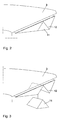
- Fig. 2 shows the rear, d. H. the rotor facing away from the engine room 3.
- a recess 12 is provided in the lower in Fig. 2, d. H. the sea surface facing side of the lining of the machine house 3, a recess 12 is provided.
- the recess 12 receives the retracted rescue capsule 11 in a form-fitting manner.
- the retracted rescue capsule 11 is integrated into the outer design of the machine house and thus offers an aesthetically pleasing sight.
- Fig. 3 the beginning of the descent of the rescue capsule 11 in Fig. 2 is shown.
- the rescue capsule 11 is slightly detached from the recess 12 of the lining of the machine house 3.
- the rescue capsule 11 is triangular in cross-section.
- the escape capsule 11 released from the recess 12 is shown in its overall tent-shaped shape.
- a roller 14 from which the rope rolls, arranged.
- a (not shown) brake is provided on the roller 14 .
- the pulley may also be fastened inside the rescue capsule 11 or on the machine housing 3
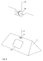
- the escape capsule 11 shown in FIG. 5 has a capsule door 16 in a roof wall.
- the service personnel accesses through an exit opening provided in the recess 12 and opens the capsule door 11.
- the service personnel can get into the rescue capsule 11, then close the capsule door 16 from the inside and drive protected from the weather after rappelling on the sea surface , Exit opening and capsule door in case of danger, a direct connection between the interior of the machine house and the interior of the rescue capsule 11.
- the rescue capsule 11 in Fig. 5 is shown during rappelling.
- FIG. 6 shows the rescue capsule 11 in a form integrated in the spinner of the rotor 6.
- the service personnel who are e.g. stops for maintenance in the rotor hub 17, climb into the spinner to get into the escape pod 11.
- a rescue capsule 11 is shown, which is arranged in the normal position below the machine house 3. Below the machine house 3, a rail profile 18 is provided, on which the rescue capsule 11 hangs in the normal position.
- the area of the rescue capsule 11 facing the machine house 3 is flattened.
- the capsule door is provided in the flattened area. The service personnel can enter the escape pod 11 through the capsule door from the machine house 3. Thereafter, the escape pod 11 is roped off.
Abstract
Description
Die Erfindung betrifft eine Windenergieanlage für den off-shore Einsatz.The invention relates to a wind energy plant for off-shore use.
Windenergieanlagen zur Erzeugung von Strom finden zunehmend Verbreitung. Die Anlagen weisen einen Turm auf, an dessen oberem Ende ein Maschinenhaus angeordnet ist, das einen Generator und bei bestimmten Anlagen ein Getriebe aufnimmt. Bei Defekten der Anlagen und Wartungsarbeiten an dem Generator oder dem Getriebe muss das Servicepersonal durch den Turm in das Maschinenhaus steigen. Das ist kraft- und zeitaufwendig.Wind turbines for generating electricity are becoming increasingly popular. The plants have a tower, at the upper end of which a nacelle is arranged, which receives a generator and, in the case of certain plants, a transmission. In the event of equipment breakdowns and maintenance work on the generator or gearbox, the service personnel must climb through the tower into the machine house. This is powerful and time consuming.
Darüber hinaus sind im Maschinenhaus oder im Turm der Windenergieanlage Transformatoren untergebracht. Gerade bei Reparaturarbeiten können durch Defekt an den Transformatoren Brände verursacht werden. Im Brandfall ist das Servicepersonal dann möglicherweise im Maschinenhaus eingeschlossen. Somit besteht das Problem, das Servicepersonal im Brandfall, z.B. aus dem Maschinenhaus heraus, in Sicherheit zu bringen. Eine Rettung mittels Helikopter dauert hier meist zu lange und außerdem ist der Anflug des Helikopters zum Dach des Maschinenhauses im Brandfall gefährlich.In addition, transformers are housed in the nacelle or tower of the wind turbine. Especially during repair work, fires can be caused by a defect in the transformers. In case of fire, the service personnel may be trapped in the machine house. Thus, there is the problem of service personnel in case of fire, e.g. out of the nacelle, to safety. Rescue by helicopter usually takes too long here and also the approach of the helicopter to the roof of the engine house in case of fire is dangerous.
Im on-shore Einsatz sind Windenergieanlagen bekannt, in deren Maschinenhaus eine Ausstiegsluke bodenseitig angebracht ist. Aus Sicherheitsgründen arbeitet das Servicepersonal im Maschinenhaus mit einem umgeschnallten Gurt. Im Brandfall ist das Servicepersonal angehalten, ein Ende eines Sprungseils im Gurt einzuhaken. Das angeseilte Servicepersonal springt danach durch die geöffnete Luke und wird durch das sich von einer Rolle gebremst abwickelnde Sprungseil sicher zum Boden abgeseilt. Derartige Rettungssysteme eignen sich nicht für den off-shore Einsatz, weil ein Abseilen des Servicepersonals in das Meer geltenden Sicherheitsbestimmungen nicht genügt. Insbesondere im Winter wäre das Abseilen ins Meer mit der Gefahr lebensgefährlicher Unterkühlungen verbunden. Zwar wäre die Durchführung von Wartungs- und Reparaturarbeiten bei dem beschriebenen Rettungssystem in Überlebensanzügen gestattet, jedoch bei den üblicherweise im Maschinenhaus herrschenden Raumtemperaturen von bis zu 50°C sehr beschwerlich.In onshore use, wind turbines are known in whose engine house an exit hatch is mounted on the bottom side. For safety reasons, the service staff in the nacelle works with a strapped belt. In case of fire, the service personnel is encouraged to hook one end of a jump rope in the belt. The roped-up service personnel then jump through the open hatch and is safely roped to the ground by the jump rope, which is braked by a roll. Such rescue systems are not suitable for off-shore use because rappelling of service personnel into the sea does not meet safety regulations. Especially in winter, rappelling into the sea would be associated with the danger of life-threatening hypothermia. Although the execution of maintenance and repair of the described rescue system in survival suits would be allowed, but at the prevailing usually in the engine room room temperatures of up to 50 ° C very cumbersome.
Rettungskonzepte für auf See befindliche Objekte sind bekannt. In der DE 202 02 214 U1 ist eine Rettungsvorrichtung für Personen auf einem Schiff offenbart. Dort ist ein integraler Bestandteil des Schiffs als Rettungsvorrichtung ausgebildet, der im Gefahrenfall aus dem Schiffsrumpf ausgeklinkt werden kann.Rescue concepts for objects at sea are known. DE 202 02 214 U1 discloses a rescue device for persons on a ship. There, an integral part of the ship is designed as a rescue device, which can be disengaged from the hull in case of danger.
Die DE 42 05 946 A1 offenbart eine Rettungsinsel für Bohrplattformen. Dabei ist eine am Meeresgrund angeordnete Rettungsinsel vorgesehen, die im Gefahrenfall an die Wasseroberfläche aufsteigt und dort aufblasbar ist. Aus der DE 250 0975 A1 ist eine ständig mit Personal besetzte Ölplattform mit einer Rettungskapsel bekannt.DE 42 05 946 A1 discloses a liferaft for drilling platforms. In this case, a life raft arranged on the seabed is provided, which rises in the event of danger to the water surface and there is inflatable. From DE 250 0975 A1 a constantly staffed with oil rig is known with a rescue capsule.
Aus der DE 102 22 472 A1 ist eine Windenergieanlage bekannt, die über eine entlang einer Schiene verfahrbare, einklinkbare Kabine oder ganzes Schiff versorgbar istFrom DE 102 22 472 A1 a wind power plant is known, which can be supplied via a movable along a rail, latchable cabin or entire ship
Die genannten Konzepte eignen sich nicht zur Rettung von Servicepersonal aus Windenergieanlagen.The above concepts are not suitable for the rescue of service personnel from wind turbines.
Es ist Aufgabe der vorliegenden Erfindung, eine Windenergieanlage mit einem einfachen und kostengünstigen Rettungssystem und ein Verfahren zur Rettung von Servicepersonal aus einer Windenergieanlage zur Verfügung zu stellen.It is an object of the present invention to provide a wind turbine with a simple and inexpensive rescue system and a method for rescuing service personnel from a wind turbine.
Die Aufgabe wird durch eine eingangs genannte Windenergieanlage gelöst, die die Merkmale des Anspruchs 1 aufweist.The object is achieved by a wind turbine mentioned above, which has the features of claim 1.
Auf der Betriebsmittelplattform können zu wartende oder zu reparierende Einrichtungen, wie der Generator, Getriebe oder Transformatoren untergebracht sein. Die Betriebsmittelplattform ist hier als ein umfassender Begriff zu verstehen, der u.a. eine im Bodenabschnitt des Turms angeordnete Containerplattform, im mittleren Abschnitt des Turms angeordnete Turmplattformen und ein im Turmkopf angeordnetes Maschinenhaus und auch die zur Wartung zugängliche Rotornabe mit umfasst. Die Windenergieanlage ist zu Wartungszwecken von Servicepersonal begehbar.The equipment platform may house facilities to be serviced or repaired, such as the generator, transmission or transformers. The resource platform is to be understood here as a comprehensive term which i.a. a arranged in the bottom portion of the tower container platform, arranged in the central portion of the tower tower platforms and arranged in the tower head nacelle and also accessible for maintenance rotor hub with. The wind turbine is accessible for maintenance by service personnel.
Das Servicepersonal wird mit einen Beförderungsmittel, insbesondere einem Schiff oder einem Helikopter zur off-shore Windenergieanlage befördert. Die Windenergieanlage weist in einer bevorzugten Ausführungsform einen verschließbaren Wartungszugang für das heran beförderte Servicepersonal auf. Das ist beispielsweise eine Turmtür am meeresbodenseitigen Ende des Turms, insbesondere für mit einem Versorgungsschiff befördertes Servicepersonal. Das Servicepersonal gelangt durch Öffnen des Wartungszugangs in einen Innenraum des Turms der Windenergieanlage. Der Wartungszugang kann in einer anderen Ausführungsform der Erfindung ein Mannloch am Dach des Maschinenhauses am oberen Ende des Turmes für durch einen auf einer Landefläche am Maschinenhaus landenden Helikopter befördertes Servicepersonal sein. Das Maschinenhaus kann bis zu 100 Metern oberhalb der Meeresoberfläche vorgesehen sein.The service personnel are transported to the offshore wind turbine by means of a means of transport, in particular a ship or a helicopter. In a preferred embodiment, the wind energy installation has a closable maintenance access for the service personnel conveyed up there. The For example, is a tower door at the sea bottom end of the tower, especially for promoted with a supply ship service personnel. The service personnel arrive by opening the maintenance access in an interior of the tower of the wind turbine. In another embodiment of the invention, the service access may be a manhole on the roof of the machine house at the top of the tower for service personnel carried by a helicopter landing on a landing area at the engine house. The machine house can be provided up to 100 meters above the sea surface.
Das Rettungsmittel ist vor dem Gefahrenfall, auch wenn kein Servicepersonal bei der Windenergieanlage ist, in Verbindung mit der Windenergieanlage. Das ist auch der Normalzustand der Windenergieanlage. Das Rettungsmittel ist im Normalzustand bei der Windenergieanlage positioniert, insbesondere an ihr angeordnet. Es ist im Wesentlichen ständig mit der Windenergieanlage verbunden. Das Rettungsmittel wird vor dem Gefahrenfall allenfalls, um beispielsweise selber gewartet oder ausgetauscht zu werden, von der Windenergieanlage entfernt. Im Gefahrenfall ist das Rettungsmittel zum Transport des sich auf der Betriebsmittelplattform aufhaltenden Servicepersonals zur Meeresoberfläche bestimmt.The rescue device is in front of the danger case, even if there are no service personnel with the wind energy plant, in connection with the wind energy plant. This is also the normal state of the wind turbine. The rescue means is positioned in the normal state at the wind turbine, in particular arranged at her. It is essentially constantly connected to the wind turbine. The rescue means is removed before the danger at best, for example, to be serviced or replaced, removed from the wind turbine. In the event of danger, the rescue device is intended for transporting the service personnel to the sea surface, which are located on the equipment platform.
Es liegt vorzugsweise eine mechanische Verbindung zwischen Windenergieanlage und Rettungsmittel durch Seile Aufhängungen, Führungsschienen o. Ä. vor. Das Rettungsmittel ist bis zum Gefahrenfall durch die mechanische Verbindung ständiger Bestandteil der Windenergieanlage. Es kommt im Gefahrenfall zum Einsatz. Dann ist es zum Transport und vorzugsweise zur Aufnahme des Servicepersonals bestimmt, wenn sich solches gerade zu Wartungszwecken in der Windenergieanlage aufhält.It is preferably a mechanical connection between the wind turbine and rescue means by ropes suspensions, guide rails o. Ä. in front. The rescue device is a permanent component of the wind turbine up to the point of danger due to the mechanical connection. It is used in case of danger. Then it is intended for transport and preferably for receiving the service personnel, if such is just for maintenance purposes in the wind turbine.
Das Beförderungsmittel und das Rettungsmittel sind günstigenfalls voneinander getrennt. Das Beförderungsmittel ist im Rahmen des erfindungsgemäßen Rettungssystems nicht zur Rettung des Servicepersonals im Gefahrenfall bestimmt. Ebenso sind vorzugsweise der Wartungszugang und die direkte Verbindung zwischen Innenraum der Betriebsmittelplattform und Rettungsmittel voneinander getrennt.The means of transport and the life-saving means are at best separated. The means of transport is not intended in the context of the rescue system according to the invention for the rescue of the service personnel in case of danger. Likewise, preferably the maintenance access and the direct connection between the interior of the resource platform and rescue means are separated from each other.
Im Gefahrenfall kann das Servicepersonal direkt von der Betriebsmittelplattform gerettet werden, zu der es vorher ggf. aus anderen Bereichen der Windenergieanlage flüchtet. Das Rettungsmittel ist dazu günstigenfalls an der Betriebsmittelplattform angeordnet. Das Servicepersonal braucht nicht zu einem von der Betriebsmittelplattform beabstandeten Wartungszugang flüchten. Das erfindungsgemäße Rettungskonzept eignet sich insbesondere zur Rettung des Servicepersonals direkt von der Betriebsmittelplattform, d. h. aus dem Gefahrenbereich, in dem sie sich das Servicepersonal zu Servicearbeiten aufhält und der besonders brandgefährdet ist.In the event of danger, the service personnel can be rescued directly from the equipment platform to which it may previously have fled from other areas of the wind turbine. At best, the rescue device is at the resource platform arranged. The service personnel need not escape to a maintenance access remote from the resource platform. The rescue concept according to the invention is suitable, in particular, for rescuing the service personnel directly from the equipment platform, ie from the danger area in which the service personnel spend time servicing them and which is particularly at risk from fire.
Vorzugsweise ist eine direkte, den Umstieg des Servicepersonals gestattende Verbindung zwischen einem Innenraum der Betriebsmittelplattform und dem Rettungsmittel vorgesehen. Diese Verbindung kann als Übergang ausgebildet sein. Dadurch kann das Servicepersonal direkt aus dem Innenraum der Betriebsmittelplattform in das Rettungsmittel umsteigen. Die direkte Verbindung ist vorzugsweise zwischen dem Innenraum der Betriebsmittelplattform und einem Innenraum des Rettungsmittels vorgesehen.Preferably, a direct, the transfer of service personnel gestattende connection between an interior of the resource platform and the rescue means is provided. This connection can be designed as a transition. This allows the service personnel to change directly from the interior of the equipment platform in the rescue. The direct connection is preferably provided between the interior of the resource platform and an interior of the rescue means.
Im Normalzustand hält sich kein Servicepersonal in der Windenergieanlage auf. Die Windenergieanlage ist normalerweise personenlos und nur zur Wartungsarbeiten durch Servicepersonal belegt. Der Gefahrenfall liegt vor, wenn sich Servicepersonal auf der Windenergieanlage aufhält und ein Gefahrentatbestand auftritt. Das kann insbesondere Feuer in der Windenergieanlage oder der unkontrollierte durchgehende Rotor der Windturbine sein.In the normal state, there are no service personnel in the wind turbine. The wind turbine is normally unmanned and only used for maintenance by service personnel. The danger exists when service personnel are present on the wind turbine and a hazardous event occurs. This can be in particular fire in the wind turbine or the uncontrolled rotor through the wind turbine.
Vorzugsweise ist das Servicepersonal in dem Rettungsmittel aufnehmbar, es kann einen Innenraum zur Aufnahme aufweisen. Bei dem Rettungsmittel kann es sich um unten beschriebene Rettungskapseln, Rettungskörbe oder Ähnliches handeln.Preferably, the service personnel in the rescue means is receivable, it may have an interior for receiving. The rescue means may be rescue capsules, rescue baskets or the like described below.
In einer bevorzugten Ausführungsform der Erfindung weist die Betriebsmittelplattform eine Ausstiegsöffnung für das Servicepersonal und das Rettungsmittel eine Einstiegsöffnung, vorzugsweise eine Rettungskapseltür, auf. Beide Öffnungen liegen einander gegenüber und bilden eine Ausführungsform der direkten Verbindung aus. Vorzugsweise sind die direkte Verbindung und der Wartungszugang voneinander getrennt. Sie können voneinander beabstandet sein.In a preferred embodiment of the invention, the resource platform has an exit opening for the service personnel and the rescue means an access opening, preferably a rescue capsule door on. Both openings face each other and form an embodiment of the direct connection. Preferably, the direct connection and the maintenance access are separated from each other. They can be spaced apart.
Das Rettungsmittel ist vorzugsweise von brandgefährdeten oder elektrischen Einrichtungen im Wesentlichen befreit. Gegenüber dem Beförderungsmittel ist das Rettungsmittel somit nicht der Gefahr ausgesetzt, selbst in Brand zu geraten oder selbst Auslöser eines Brandes an der Windenergieanlage zu sein. Rettungsmittel und Beförderungsmittel sind nicht identisch.The rescue means is preferably substantially free of fire-prone or electrical devices. Opposite the means of transport is the Rescue means thus not exposed to the danger of being on fire or even being the trigger of a fire at the wind turbine. Rescue aids and means of transport are not identical.
Zum Transportieren des Rettungsmittels entlang des Turms kann eine Hinunterlassvorrichtung vorgesehen sein.For transporting the rescue device along the tower, a knockout device may be provided.
In einer Ausführungsform der Erfindung kann die Hinunterlassvorrichtung eine Schiene aufweisen, an der das Rettungsmittel zur Meeresoberfläche geführt wird. In einer anderen Ausführungsform weist sie wenigstens ein Seil auf, an dem das Rettungsmittel abseilbar ist.In one embodiment of the invention, the knock-down device may comprise a rail on which the rescue aid is guided to the sea surface. In another embodiment, it has at least one rope on which the rescue means can be abseilbar.
Es ist auch denkbar, dass das Rettungsmittel einen Gleitschirm aufweist. Das Servicepersonal besteigt das Rettungsmittel, klinkt es an der Betriebsmittelplattform aus und schwebt in ihm zur Meeresoberfläche. Statt eines Gleitschirms ist auch ein Fallschirm oder Ähnliches verwendbar. Die Rettungseinrichtung ist in dieser Ausführungsform besonders kostengünstig.It is also conceivable that the rescue means has a paraglider. The service personnel board the rescue agent, latches it out at the resource platform and floats in it to the sea surface. Instead of a paraglider, a parachute or the like is usable. The rescue device is particularly inexpensive in this embodiment.
In einer weiteren Ausführungsform der Erfindung ist das Rettungsmittel als Rettungstorpedo ausgebildet, der aus der Betriebsmittelplattform nach dem Besteigen durch das Servicepersonal ausgeklinkt werden kann, und der dann zur Meeresoberfläche fällt. Er ist vorzugsweise geschlossen und im Wesentlichen wasserdicht und stromlinienförmig, insbesondere lang gestreckt, ausgebildet. Die Stromlinienform des Rettungstorpedos erlaubt ein die Aufschlagkraft dämpfendes Eintauchen in das Meer. Es können weitere dämpfende Haltemittel, wie elastische Gurte oder Sitze für das Servicepersonal in dem Rettungstorpedo vorgesehen sein. Der Rettungstorpedo kann auch, beispielsweise durch ein mit dem Turm verbundenes Gummiseil, gedämpft fallen. Solche Rettungstorpedos sind bisher nur für eine Mehrzahl von Personen, als Rettungsmittel für die Besatzung von Bohrinseln bekannt.In a further embodiment of the invention, the rescue means is designed as a rescue torpedo, which can be disengaged from the resource platform after boarding by the service personnel, and which then falls to the sea surface. It is preferably closed and substantially waterproof and streamlined, in particular elongated, formed. The streamlined shape of the rescue torpedo allows a dip in the sea, which reduces the impact force. There may be provided further damping support means, such as elastic straps or seats for service personnel in the rescue torpedo. The rescue torpedo can also be dampened, for example, by a rubber cord connected to the tower. Such rescue torpedoes have hitherto been known only to a large number of persons as rescue equipment for the crew of drilling rigs.
Vorzugsweise ist das Rettungsmittel aber mittels einer Abseileinrichtung entlang des Turms zur Meeresoberfläche abseilbar. Das Servicepersonal wird so schnell aus der Gefahr gerettet. Das Rettungsmittel wird vorzugsweise durch wenigstens ein Seil im Wesentlichen senkrecht zur Meeresoberfläche, neben dem Turm, von einer Betriebsmittelplattform aus, abgeseilt. Dabei kann es durch einen den Turm umlaufenden Ring geführt werden, dessen Innendruchmesser wenigstens dem größten Turmdurchmesser entspricht. In einer weiteren Ausführungsform der Erfindung umläuft das Rettungsmittel den Turm. Es ist umlaufend begehbar und wird durch eine in der Betriebsmittelplattform angeordnete Luke bestiegen. Es wird vom Turm geführt abgeseilt.Preferably, however, the rescue means can be abseilbar by means of a rappelling device along the tower to the sea surface. The service staff is so quickly rescued from danger. The rescue means is preferably descented by at least one rope substantially perpendicular to the sea surface, adjacent the tower, from a resource platform. It can be through a tower be performed circumferential ring, the inner diameter of which corresponds at least to the largest tower diameter. In a further embodiment of the invention the rescue means circulates the tower. It is circumferentially accessible and is climbed by a hatch located in the resource platform. It is roped off guided by the tower.
Insbesondere das Abseilen neben dem Turm kann mit Hilfe verschiedener Vorrichtungen geschehen. In einer Variante wird das Seil heruntergelassen und das Servicepersonal klinkt sich nacheinander mit einer an dem Gurt vor dem Bauch des Servicepersonals angebrachten Bremsvorrichtung in das Seil ein und seilt sich in eine Rettungsinsel oder Ähnliches ab.In particular, the rappelling next to the tower can be done by means of various devices. In a variant, the rope is lowered and the service personnel latches one after another with a mounted on the belt in front of the belly of the service personnel braking device in the rope and secluded in a liferaft or the like.
In einer bevorzugten Ausführungsform der Erfindung kann das eine Ende eines Seils mit der Betriebsmittelplattform verbunden sein, und ein anderes Ende des Seils kann an einer außerhalb des Rettungsmittels angeordneten Seilrolle befestigt sein, auf der ein Seilvorrat aufgerollt ist. Es können z.B. Nylonseile oder Stahlseile verwendet werden.In a preferred embodiment of the invention, one end of a rope may be connected to the resource platform, and another end of the rope may be attached to a pulley disposed outside the rescue means on which a cord stock is rolled up. It can e.g. Nylon ropes or steel cables are used.
Die Seilrolle kann auch oberhalb der Betriebsmittelplattform, beispielsweise auf einem Galgen gelagert sein. Dabei ist das Rettungsmittel durch eine Bodenöffnung der Betriebsmittelplattform besteigbar.The pulley may also be mounted above the equipment platform, for example on a gallows. In this case, the rescue means by a bottom opening of the resource platform is mountable.
Die Verwendung von Seilen macht die Abseileinrichtung wartungsarm und kostengünstig in der Anschaffung.The use of ropes makes the abseiling device low-maintenance and inexpensive to purchase.
Die Abseileinrichtung kann eine Bremse aufweisen, mittels der die Abseilgeschwindigkeit des Rettungsmittels verringerbar ist. Die Bremse ist vorzugsweise an der Seilrolle angeordnet. Beispielsweise ist dazu die Abrollgeschwindigkeit des auf der Seilrolle aufgerollten Seils durch eine an der Seilrolle angeordnete Fliehkraftbremse steuerbar. Durch Minderung der Abseilgeschwindigkeit wird die Gefahr von Verletzungen beim Servicepersonal verringert. Insbesondere bei einer außerhalb des Rettungsmittels angeordneten Seilrolle kann eine vom Rettungsmittel aus bedienbare Steuereinrichtung, z.B. ein Steuergestänge oder einen Bowdenzug, vorgesehen sein, mit der die Abseilgeschwindigkeit gebremst oder das Rettungsmittel gestoppt werden kann.The abseiling device may have a brake by means of which the abseiling speed of the rescue device can be reduced. The brake is preferably arranged on the pulley. For example, the unwinding speed of the cable rolled up on the cable pulley can be controlled by a centrifugal brake arranged on the cable pulley. Reducing the speed of descent reduces the risk of personal injury to service personnel. Particularly in the case of a pulley arranged outside the rescue means, a control device which can be operated from the rescue means, for example a control linkage or a Bowden cable, can be provided with which the speed of descent can be braked or the rescue means can be stopped.
Vorzugsweise wird das Rettungsmittel von der Betriebsmittelplattform aus bestiegen, an der das Rettungsmittel angeordnet ist. Danach wird das Rettungsmittel aus der Betriebsmittelplattform ausgeklinkt, um dann bemannt durch die Herablassvorrichtung zur Meeresoberfläche abzufahren. Es kann günstigerweise auch eine Steuereinrichtung für die Herablassvorrichtung an einer Turmtür vorgesehen sein. Sich bei der Turmtür aufhaltendes Servicepersonal kann das Rettungsmittel von einer oberen Betriebsmittelplattform, z.B. dem Maschinenhaus, unbemannt zur Meeresoberfläche herunterlassen und es erst dann, aus der Turmtür heraus, direkt besteigen. So wird eine Rettung des Servicepersonals ermöglicht, dem der sofortige Zustieg in das Rettungsmittel versperrt ist.Preferably, the rescue means is boarded from the resource platform on which the rescue means is located. Thereafter, the rescue means is disengaged from the resource platform, then manned by the lowering device to descend to the sea surface. It can also be conveniently provided a control device for the lowering device on a tower door. Tower-service personnel may be able to access the rescue agent from an upper resource platform, e.g. the machine house, let go unmanned to the sea surface and only then climb directly out of the tower door. Thus, a rescue of the service personnel is made possible, which is the immediate access to the rescue means locked.
Es ist denkbar, eine herkömmliche, aufblasbare Rettungsinsel an dem Rettungsmittel anzuordnen. Die Rettungsinsel ist hier bei der Betriebsmittelplattform in aneinandergefügten Halbschalen gelagert. Sie wird im Bedarfsfall automatisch aufgeblasen. Die abgesprengten Halbschalen können durch Halteeinrichtungen am Herunterfallen gehindert werden. Die Rettungsinsel wird auf einer Bodenplatte herabgelassen oder Ihr Boden wird vor dem Einsteigen des Servicepersonals verstärkt, um das eingestiegene Servicepersonal beim Herablassen zu tragen. Rettungsinseln haben den Vorteil, Platz sparend lagerbar zu sein. Allerdings sind sie wartungsintensiv und die Aufblasvorrichtung kann im Gefahrenfall versagen. Darüber hinaus muss sie nach Erlangung der Ablegereife ersetzt werden. Um auf eine Bodenverstärkung verzichten zu können, ist es auch denkbar, die Rettungsinsel unbemannt abzuseilen. Das Servicepersonal wird dann separat in Überlebensanzügen abgeseilt, um die Rettungsinsel dann aus dem Meer heraus zu besteigen.It is conceivable to arrange a conventional, inflatable liferaft on the rescue means. The liferaft is stored here in the equipment platform in abutting half shells. It is automatically inflated if necessary. The split-off shells can be prevented from falling down by holding devices. The liferaft is lowered onto a floor slab or your floor is reinforced before boarding the service personnel to carry the boarded-in service personnel when lowering. Liferafts have the advantage of being space-saving storable. However, they are maintenance intensive and the inflator may fail in case of danger. In addition, it must be replaced after obtaining the Ablegereifeife. In order to be able to do without a soil reinforcement, it is also conceivable to rappel unmanned the liferaft. The service personnel are then roped off separately in survival suits to climb the liferaft out of the sea.
In einer weiteren, besonders sicheren Ausführungsform der Erfindung ist das Rettungsmittel als schwimmfähige Rettungskapsel ausgebildet. Die Rettungskapsel kann bei Brand umgehend bestiegen und herabgelassen werden. Rettungskapseln können vollständig abgeschlossen werden, und sie sind damit vom Wetter unabhängiger. Vorteilhafter Weise braucht das Servicepersonal keine Überlebensanzüge anlegen. Die Rettungskapsel kann Auftriebskörper und Fender aufweisen, die ihre Sicherheit zusätzlich erhöhen.In a further, particularly safe embodiment of the invention, the rescue means is designed as a buoyant rescue capsule. The rescue capsule can be climbed and lowered immediately in case of fire. Rescue capsules are completely self-contained, making them more independent of the weather. Advantageously, the service staff does not need to create survival suits. The rescue capsule may have buoyancy bodies and fenders, which additionally increase their safety.
Insbesondere die Rettungskapsel kann, zur Ausbildung eines Faradayschen Käfigs, ein umlaufendes, elektrisch leitendes Material aufweisen und ein Erdungsseil enthalten, dessen Länge dem maximalen Abstand zwischen der Meeresoberfläche und dem Turmkopf entspricht. Das Erdungsseil wird im Gefahrenfall, bei Unwetter mit einem Ende zur Meeresoberfläche herabgelassen. Damit sind über das Erdungsseil mögliche Blitzeinschläge in die Windenergieanlage oder in die Rettungskapsel in das Meer ableitbar.In particular, the escape pod can, to form a Faraday cage, have a circumferential, electrically conductive material and a grounding cable, the length of which corresponds to the maximum distance between the sea surface and the tower head. The ground wire is lowered in case of danger, in case of bad weather with one end to the sea surface. Thus, possible lightning strikes in the wind turbine or in the rescue capsule in the sea can be derived via the earthing cable.
In einer weiteren bevorzugten Ausführungsform der Erfindung ist das Rettungsmittel als Korb kostengünstig ausgebildet. Der Korb ist schwimmfähig.In a further preferred embodiment of the invention, the rescue means is designed as a basket cost. The basket is buoyant.
Die oben beschriebenen Rettungsmittel enthalten vorzugsweise Schwimmwesten, Überlebensanzüge, eine Notration und Verbandsmaterial. Ebenso können dort Signaleinrichtungen, wie Leuchtraketen oder Notsignalsender, als auch ein Paddel vorhanden sein. Darüber hinaus kann ein Wurfseil zum Einholen des auf dem Meer treibenden Rettungsmittels vorgesehen sein.The rescue means described above preferably include life jackets, survival suits, emergency rations and bandages. Likewise, there may be signal devices, such as flares or distress signal transmitter, as well as a paddle. In addition, a throwing rope may be provided for retrieving the seaborne rescue agent.
Vorzugsweise ist der Hinunterlassvorrichtung eine Dämpfungsvorrichtung zugeordnet, mit der ein Fall des Rettungsmittels in ein Wellental, nach dem Aufsetzen auf einem Wellenberg, dämpfbar ist. Durch die Dämpfungsvorrichtung wird die Gefahr von Verletzungen des Servicepersonals beim Übergang vom Abseilen zum Treiben auf dem Meer vermindert.Preferably, the Hinunterlassvorrichtung is associated with a damping device with which a case of the rescue means in a wave trough, after placement on a wave crest, is damped. The damping device reduces the risk of injuries to service personnel during the transition from rappelling to drifting at sea.
In einer weiteren bevorzugten Ausführungsform der Erfindung ist das Rettungsmittel durch eine Ausklinkvorrichtung aus der Herunterlassvorrichtung, insbesondere dem Seil, ausklinkbar, wenn es die Meeresoberfläche erreicht hat. Das ausgeklinkte Rettungsmittel kann so aus der Gefahrenzone unter der Windenergieanlage wegtreiben oder mit Hilfe eines am Rettungsmittel vorgesehenen Motors aus der Gefahrenzone fahren.In a further preferred embodiment of the invention, the rescue means can be unlatched by a release device from the lowering device, in particular the rope, when it has reached the sea surface. The unlatched rescue means can thus expel from the danger zone under the wind turbine or drive with the help of an engine provided on the rescue means from the danger zone.
Die Aufgabe wird in einem weiteren Aspekt durch die Merkmale des Anspruchs 5 gelöst. In dieser Ausbildung der Erfindung ist das Rettungsmittel Teil einer Befahrvorrichtung zu Wartungszwecken für die Windenergieanlage. Eine Heraufziehvorrichtung weist dazu vorzugsweise einen Antrieb auf. Hinunterlass- und Heraufziehvorrichtung ermöglichen es, das Rettungsmittel hinunter zu lassen, vorzugsweise abzuseilen, und wieder zur Betriebsmittelplattform herauf zu ziehen. Das hinuntergelassene und z.B. auf dem Schiffsdeck des Serviceschiffes kurzfristig abgesetzte Rettungsmittel wird einschließlich des zugestiegenen Servicepersonals mit dem Antrieb zum Turmkopf hochgezogen. Ein mühseliger Leiteraufstieg durch den Turm wird dem Servicepersonal somit erspart.The object is achieved in a further aspect by the features of claim 5. In this embodiment of the invention, the rescue means is part of a driving device for maintenance purposes of the wind turbine. A pull-up device preferably has a drive for this purpose. Lowering and pulling-up device make it possible to lower the life-saving device preferably to rappel and pull up to the resource platform again. The sunken down and, for example, on the ship's deck of the service ship briefly resigned rescue means is drawn up including the relegated service personnel with the drive to the tower head. An arduous ladder climb through the tower is thus spared the service staff.
Das Rettungsmittel kann an unterschiedlichen Positionen an der Betriebsmittelplattform im Normalzustand angeordnet sein. Vorzugsweise ist es in der Betriebsmittelplattform, insbesondere dem Maschinenhaus, integriert und bietet so wenig Angriffsfläche für den Wind. Dabei können Außenwandungen des Rettungsmittels mit Außenwandungen der Betriebsmittelplattform fluchten. Das Rettungsmittel kann z.B. im Bereich der Rotornabe angebracht, vorzugsweise im Spinner integriert sein. In dieser Ausführungsform der Erfindung ist das Rettungsmittel auch zu Wartungsarbeiten der Rotorblätter einsetzbar. Dazu wird jeweils ein Rotorblatt senkrecht nach unten zur Meeresoberfläche gedreht. Zur Wartung wird das bemannte Rettungsmittel an dem Rotorblatt hinunter und herauf bewegt.The rescue means may be arranged at different positions on the resource platform in the normal state. Preferably, it is integrated in the equipment platform, in particular the machine house, and thus offers little attack surface for the wind. In this case, outer walls of the rescue device can be aligned with outer walls of the equipment platform. The rescue means may e.g. mounted in the region of the rotor hub, preferably be integrated in Spinner. In this embodiment of the invention, the rescue means can also be used for maintenance work of the rotor blades. For this purpose, a rotor blade is rotated vertically down to the sea surface. For maintenance, the manned rescue device is moved down and up the rotor blade.
Das Rettungsmittel kann aber auch an einem meerseitig der Betriebsmittelplattform, insbesondere dem Maschinenhaus, angeordneten Gestänge eingehängt sein. Diese Position eignet sich zur Wartung der Turmaußenwandung. Dazu wird das bemannte Rettungsmittel am Turm hinunter und herauf bewegt. Mit Hilfe einer Windnachführeinrichtung kann so der Turm allseitig gewartet werden.The rescue means may also be mounted on a sea side of the equipment platform, in particular the nacelle, arranged linkage. This position is suitable for maintenance of the tower outer wall. For this, the manned rescue equipment is moved down the tower and up. With the help of a Windnachführeinrichtung so the tower can be maintained on all sides.
In einer weiteren Ausführungsform der Erfindung sind zwei Rettungsmittel vorhanden, günstigenfalls in den oben genannten Positionen, am Spinner und unterhalb des Maschinenhauses. Somit können sowohl die Rotorblätter, als auch die Turmaußenwandung gewartet werden.In a further embodiment of the invention, two rescue means are present, at best in the above-mentioned positions, on the spinner and below the machine house. Thus, both the rotor blades, and the Turmaußenwandung can be maintained.
Es ist auch möglich, das Rettungsmittel an einer seitlichen Verkleidung des Maschinenhauses oder an der dem Rotor abgewandten Seite der Verkleidung zu positionieren. Das Rettungsmittel kann insbesondere durch einen Schwenkarm aus seinem Normalzustand in einen Zustand gebracht werden, in dem es vom Servicepersonal bestiegen werden kann.It is also possible to position the rescue means on a side panel of the machine house or on the side of the panel facing away from the rotor. The rescue means can be brought in particular by a swivel arm from its normal state in a state in which it can be climbed by the service personnel.
Günstigenfalls ist ein Antrieb der Heraufziehvorrichtung als fernsteuerbare Antriebswinde ausgebildet, mit einem Empfänger, die mittels eines auf einem Serviceschiff anordnerbaren Senders gesteuert werden kann. Wenn das Serviceschiff mit dem Servicepersonal auf dem Weg zur Windenergieanlage ist, kann mittels des Senders die Abseileinrichtung des im Turmkopf befindlichen Rettungsmittels angesteuert und herabgelassen werden. In besonders zeitsparender Weise wird das Rettungsmittel auf das Deck des Serviceschiffes abgeseilt, wo das Servicepersonal zusteigt. Dazu können am Boden des Rettungsmittels Dämpfungsmittel angeordnet sein, die das Stampfen des Serviceschiffes bei Seegang dämpfen.Conveniently, a drive of the pull-up device is designed as a remotely controllable drive winch, with a receiver that can be controlled by means of a can be arranged on a service ship transmitter. When the service ship is on the way to the wind turbine with the service personnel, the abseiling device of the rescue device located in the tower head can be activated and lowered by means of the transmitter. In a particularly time-saving manner, the life-saving device is lowered to the deck of the service ship, where the service personnel board. For this purpose, damping means may be arranged at the bottom of the rescue means, which dampen the pounding of the service vessel in swell.
Zur Erhöhung der Sicherheit, kann das Rettungsmittel mit dem Turmkopf über ein Lastseil und ein Sicherungsseil verbunden sein.To increase safety, the rescue means can be connected to the tower head via a load rope and a safety rope.
Damit das Rettungsmittel beim Hochziehen automatisch zur Ausbildung der direkten Verbindung zum Umstieg in der Maschinenhausverkleidung positioniert wird, weist das Rettungsmittel Leitprofile und der Turmkopf korrespondierende Leitprofile auf.So that the rescue means is automatically positioned to form the direct connection to the changeover in the machine housing lining during hoisting up, the rescue means has guide profiles and the tower head has corresponding guide profiles.
Vorzugsweise weist das Rettungsmittel einen Anschlagschutz auf. Insbesondere bei starkem Wind besteht die Gefahr, das Rettungsmittel schräg abzuseilen. Es kann auch zu Schaukelbewegungen des Rettungsmittels am Seil kommen. Der Anschlagschutz kann ein hartes Anschlagen des Rettungsmittels am Turm verhindern, dazu ist der Anschlagschutz als ein das Rettungsmittel umgebender Dämpfer, z.B. als Luftschlauch, der als Fender dient, ausgebildet. Es sind auch Abstandsbegrenzungsvorrichtungen zwischen Rettungsmittel und Turm denkbar.Preferably, the rescue means on a stop protection. Especially in strong winds there is a risk of raving the rescue means diagonally. It can also come to rocking movements of the rescue device on the rope. The stop guard can prevent a hard impact of the rescue means on the tower, for this purpose the stop guard as a damper surrounding the rescue means, e.g. as an air hose, which serves as a fender formed. There are also distance limiting devices between rescue means and tower conceivable.
Um insbesondere ein mehrmaliges Anschlagen am, oder ein Umwickeln des Turmes durch das am Seil herabgelassene Rettungsmittel zu verhindern, kann ein Leitseil vorgesehen sein, dessen eines Ende mit der Windenergieanlage verbunden ist und dessen anderes Ende ein Ankermittel aufweist, das in das Meer abseilbar ist. In einer Ausführungsform des Anschlagschutzes kann das eine Ende des Leitseils mit der Betriebsmittelplattform verbunden sein und das andere Ende einen Anker oder ein Gewicht aufweisen, das auf den Meeresboden abseilbar ist. Das Rettungsmittel ist hier am Leitseil zur Meeresoberfläche führbar.In order to prevent in particular a repeated impact on, or a wrapping of the tower by the lifesaving means lowered on the rope, a guide rope may be provided, one end of which is connected to the wind turbine and the other end has an anchoring means which can be abseilbar in the sea. In one embodiment of the stop guard, one end of the guide rope may be connected to the resource platform and the other end may have an anchor or a weight that can be abseilated onto the seabed. The rescue equipment can be guided here on the cable to the sea surface.
In anderen Ausführungsformen des Anschlagschutzes ist das eine Ende des Leitseils mit dem Rettungsmittel verbunden. Das Ankermittel kann in kostengünstiger Weise als Treibanker ausgebildet sein, der das Rettungsmittel in eine Richtung, vorzugsweise vom Turm weg, zieht.In other embodiments of the stop guard, one end of the guide rope is connected to the rescue means. The anchor means may be formed in a cost effective manner as a driving anchor, which pulls the rescue means in one direction, preferably away from the tower.
Es ist auch denkbar, das Ankermittel als mehrere, entlang des Leitseils angeordnete Einzelgewichte auszubilden, die während des Abseilens des Rettungsmittels nacheinander auf den Meeresboden gelangen. Die Einzelgewichte können an dem Leitseil voneinander beabstandet fixiert sein. Die Länge des Leitseils entspricht der maximalen Höhe des Rettungsmittels über der Meeresoberfläche, zuzüglich der Meerestiefe im Bereich der Windkraftanlage. Während das Leitseil zum Meeresboden gelassen wird, wird es durch die nacheinander dort auftreffenden Einzelgewichte immer wieder neu verankert.It is also conceivable to form the anchor means as a plurality of individual weights arranged along the guide rope, which successively reach the seabed during the descent of the rescue means. The individual weights may be fixed to the guide wire spaced from each other. The length of the guide rope corresponds to the maximum height of the rescue device above the sea surface, plus the depth of the sea in the area of the wind turbine. While the guide rope is left to the bottom of the sea, it is anchored again and again by the successive individual weights.
Vorzugsweise werden die Einzelgewichte aber nacheinander abgeseilt. Dadurch wird erreicht, dass die Einzelgewichte während des Abseilens des Rettungsmittels nur kurzzeitig dem möglicherweise herrschenden Wind ausgesetzt sind, der sie gegen den Turm drücken könnte. Jedes Einzelgewicht weist dazu vorzugsweise eine Bohrung zum Durchführen des Leitseils auf mit einem Innendurchmesser, der größer als der Innendurchmesser einer Bohrung eines später abzuseilenden Einzelgewichts ist. Ausgehend vom Rettungsmittel sind Haltemittel mit zunehmendem Außendurchmesser am Leitseil voneinander beabstandet fixiert. Jedes Einzelgewicht ist einem Haltemittel zugeordnet, indem sein Innendurchmesser etwas kleiner als der Außendurchmesser des ihm zugeordneten Haltemittels ist, aber größer als der Außendurchmesser der dichteren Halteelemente ist. Somit rutscht das zuerst abgeseilte Einzelgewicht mit dem größten Innendurchmesser über alle Haltemittel, und es kommt erst auf dem am weitest entfernten Haltemittel zum Stillstand, und das als nächstes abgeseilte Einzelgewicht, mit dem zweitgrößten Innendurchmesser, kommt auf dem zweit weitest entfernten Haltemittel zum Stillstand usw.Preferably, however, the individual weights are descented one after the other. This ensures that the individual weights are exposed during the descent of the rescue only briefly the possibly prevailing wind, which could press them against the tower. For this purpose, each individual weight preferably has a bore for passing through the guide cable with an inner diameter that is greater than the inner diameter of a bore of a single weight to be subsequently cut off. Starting from the rescue means holding means are fixed with increasing outer diameter on the guide wire spaced from each other. Each individual weight is associated with a holding means in that its inner diameter is slightly smaller than the outer diameter of the holding means assigned to it, but larger than the outer diameter of the denser holding elements. Thus, the first abgeseilte individual weight with the largest inner diameter slips over all holding means, and it comes only on the most distant holding means to a standstill, and the next abgeseilte single weight, with the second largest inner diameter, comes to the second most distant holding means to a standstill, etc.
In einer besonders bevorzugten Ausführungsform der Erfindung ist das Rettungsmittel im heraufgezogenen Zustand in die Verkleidung des Maschinenhauses integriert, beispielsweise, indem die Außenwandung des Rettungsmittels mit der Verkleidung des Maschinenhauses fluchtet. Durch den fluchtenden Übergang entsteht eine glatte Wandung des Maschinenhauses, an die der Wind nicht angreifen kann, wodurch ein Umstieg ohne Schwankungen und somit gefahrlos erfolgen kann.In a particularly preferred embodiment of the invention, the rescue means is integrated in the raised state in the cladding of the machine house, for example, by the outer wall of the rescue means is aligned with the cladding of the machine house. The flush transition creates a smooth Wall of the machine house, to which the wind can not attack, whereby a change without fluctuations and thus can be done safely.
Die Aufgabe wird auch durch ein Verfahren zur Rettung von Servicepersonal im Gefahrenfall von einer Windenergieanlage für den off-shore Einsatz mit einer an einem Turm oberhalb einer Meeresoberfläche angeordneten Betriebsmittelplattform gelöst, indem Servicepersonal mit einem Beförderungsmittel zur Windenergieanlage befördert wird und das Servicepersonal im Gefahrenfall von der Betriebsmittelplattform in wenigstens ein Rettungsmittel steigt, das vor dem Gefahrenfall, wenn kein Servicepersonal bei der Windenergieanlage ist, mit der Windenergieanlage in Verbindung steht und das Servicepersonal mit dem Rettungsmittel in Richtung Meeresoberfläche transportiert wird.The object is also achieved by a method for rescuing service personnel in case of danger from a wind turbine for off-shore use with a arranged on a tower above a sea surface equipment platform by service staff is transported with a means of transport to the wind turbine and the service personnel in the event of danger of the Resource platform increases in at least one rescue means, which is in front of the danger case, if no service personnel at the wind turbine, in connection with the wind turbine and the service personnel is transported with the rescue means towards the sea surface.
Vorzugsweise steigt das Servicepersonal im Gefahrenfall direkt aus dem Innenraum der Windenergieanlage in das Rettungsmittel.Preferably, the service personnel rises in the event of danger directly from the interior of the wind turbine in the rescue.
Die Erfindung wird anhand von Ausführungsbeispielen in sieben Figuren beschrieben. Dabei zeigen:
- Fig. 1
- eine Perspektivische Ansicht einer erfindungsgemäßen Windenergieanlage mit teilweise abgeseilter Rettungskapsel,
- Fig. 2
- eine perspektivische Ansicht des leeseitigen Teils des Maschinenhauses in Fig. 1 mit eingezogener Rettungskapsel,
- Fig. 3
- eine Ansicht gemäß Fig. 2 mit teilweise abgeseilter Rettungskapsel,
- Fig. 4
- eine Ansicht des Maschinenhauses gemäß Fig. 3 von Achtern mit Rettungskapsel,
- Fig. 5
- eine perspektivische Ansicht der erfindungsgemäßen Rettungskapsel,
- Fig. 6
- eine perspektivische Ansicht eines Maschinenhauses in einer zweiten Ausführungsform,
- Fig. 7
- eine perspektivische Ansicht eines Maschinenhauses in einer dritten Ausführungsform.
- Fig. 1
- a perspective view of a wind turbine according to the invention with partially sunk escape pod,
- Fig. 2
- a perspective view of the leeward part of the machine house in Figure 1 with retracted escape pod,
- Fig. 3
- a view according to FIG. 2 with a partially sunk escape pod,
- Fig. 4
- a view of the machine house of FIG. 3 from aft with rescue capsule,
- Fig. 5
- a perspective view of the rescue capsule according to the invention,
- Fig. 6
- a perspective view of a machine house in a second embodiment,
- Fig. 7
- a perspective view of a machine house in a third embodiment.
Die in Fig. 1 dargestellte Windenergieanlage 1 ist für den off-shore Einsatz bestimmt. Die Windenergieanlage 1 weist einen Turm 2 und ein auf dem Turm 2 angeordnetes Maschinenhaus 3 auf, das um eine Längsrichtung des Turmes 2 in den Wind drehbar ist. An einem luvseitigen Ende des Maschinenhauses 3 ist ein drei paarweise in einem Winkel von 120° zueinander angeordnete Rotorblätter 4 aufweisender Rotor 6 drehbar gelagert. Die Windenergieanlage 1 weist einen im Meeresboden verankerten Turmfuß (nicht eingezeichnet) auf. Oberhalb einer Meeresoberfläche 7 ist eine Servicetür 8 im Turm 2 angeordnet, durch die mit dem Serviceschiff angelandetes Servicepersonal die Windenergieanlage 1 zu Wartungs- und Reparaturarbeiten begehen kann. Dafür ist zwischen Servicetür 8 und Maschinenhaus 3 eine Leiter im Inneren des Turms 2 vorgesehen. Von der Meeresoberfläche 7 zur Servicetür 8 verläuft eine Stiegleiter 9. Die Servicetür 8 ist im Turm 2 deutlich oberhalb eines Hochwassermeeresspiegels angeordnet, damit sie auch dem Wellengang bei rauer See nicht ausgesetzt ist. Eine unterste Stiege der Stiegleiter 9 ist auf Höhe des Niedrigwassermeeresspiegels außen am Turm 2 befestigt.The wind turbine 1 shown in Fig. 1 is intended for off-shore use. The wind turbine 1 has a
Im Turm 2, dort oberhalb des Hochwassermeeresspiegels oder im Maschinenhaus 3 können Transformatoren untergebracht sein, deren Hochspannungen bei Defekten Brände verursachen können. Im Brandfall kann sich das im Turm 2 oder Maschinenhaus 3 gefangene Servicepersonal in einer aus dem Maschinenhaus 3 abseilbaren Rettungskapsel 11 in Sicherheit bringen. Dazu weist eine rotorabseitige, im Betrieb also leeseitige Verkleidung des Maschinenhauses in einem unteren, der Meeresoberfläche 7 zugewandten Bereich, eine Aussparung 12 auf. In die Aussparung 12 ist die Rettungskapsel 11 im Wesentlichen formschlüssig aufnehmbar. Das Maschinenhaus 3 weist in der Aussparung 12 eine Öffnung (nicht eingezeichnet) auf, durch die ein Zugriff auf eine Kapseltür der Rettungskapsel 11 ermöglicht wird. Somit kann das Servicepersonal im Brandfall durch die Öffnung greifen, die Kapseltür öffnen und aus dem Maschinenhaus 3 in die Rettungskapsel 11 umsteigen. Die Rettungskapsel 11 ist mit dem Maschinenhaus 3 durch ein Halteseil 13 verbunden, das von einer oberhalb der Rettungskapsel 11 angeordneten Seilwinde abrollbar ist. Im Brandfall kann das in die Rettungskapsel 11 umgestiegene Servicepersonal in der Rettungskapsel 11 einen Arretiermechanismus lösen, damit die Rettungskapsel 11 dann an dem sich gebremst abrollenden Halteseil 13 zur Meeresoberfläche 7 abseilt.In
Darüber hinaus ist an der Seilwinde eine Bremse, insbesondere eine Fliehkraftbremse (nicht eingezeichnet), vorgesehen. Die Bremse gestattet es, die Abseilgeschwindigkeit zu steuern, so dass sie eine gesundheitsschädliche Höchstgeschwindigkeit beim Auftreffen auf die Meeresoberfläche 7 nicht überschreitet. Die Bremse ermöglicht es auch, die Kabine kurz über der Meeresoberfläche 7 zu stoppen. In dieser Schwebeposition der Rettungskapsel 11 kann das Servicepersonal auf alarmierte Hilfe warten. Üblicherweise wird die Rettungskapsel 11 im Brandfall jedoch bis zur Meeresoberfläche 7 abgeseilt. Das Halteseil 13 ist in die Rettungskapsel 11 eingeklinkt. Die auf dem Meer treibende Rettungskapsel 11 kann vom Servicepersonal vom Halteseil 13 ausgeklinkt werden. Die besetzte Rettungskabine 11 ist schwimmfähig und mit Rettungswesten, Verbandsmaterial, Notproviant und Überlebensanzügen ausgestattet, so dass das Servicepersonal auch im Winter, bei niedrigen Außentemperaturen und rauer See, hinreichend lange in der Rettungskapsel aushalten kann.In addition, a brake, in particular a centrifugal brake (not shown), provided on the winch. The brake makes it possible to control the abseiling speed so that it does not exceed a harmful maximum speed when hitting the
Fig. 2 zeigt den hinteren, d. h. dem Rotor abgewandten Bereich des Maschinenhauses 3. In der in Fig. 2 unteren, d. h. der Meeresoberfläche zugewandten Seite der Verkleidung des Maschinenhauses 3 ist eine Aussparung 12 vorgesehen. Die Aussparung 12 nimmt die eingezogene Rettungskapsel 11 formschlüssig auf. Die eingezogene Rettungskapsel 11 ist in das äußere Design des Maschinenhauses integriert und bietet damit auch einen ästhetisch ansprechenden Anblick.Fig. 2 shows the rear, d. H. the rotor facing away from the
In Fig. 3 ist der Beginn des Abseilvorgangs der Rettungskapsel 11 in Fig. 2 dargestellt. Die Rettungskapsel 11 ist etwas aus der Aussparung 12 der Verkleidung des Maschinenhauses 3 herausgelöst. Die Rettungskapsel 11 ist in einem Querschnitt dreieckig ausgebildet.In Fig. 3 the beginning of the descent of the
In der Ansicht gemäß Fig. 4 eines Teils des Maschinenhauses 3 ist die aus der Aussparung 12 heraus gelöste Rettungskapsel 11 in ihrer insgesamt zeltförmigen Ausformung gezeigt. Am Dachfirst ist eine Rolle 14, von der das Seil abrollt, angeordnet. An der Rolle 14 ist eine (nicht eingezeichnete) Bremse vorgesehen.In the view according to FIG. 4 of a part of the
Alternativ kann die Seilrolle auch innerhalb der Rettungskapsel 11 oder am Maschinenhaus 3 befestigt seinAlternatively, the pulley may also be fastened inside the
Die in Fig. 5 dargestellte Rettungskapsel 11 weist in einer Dachwandung eine Kapseltür 16 auf. Im Gefahrenfall greift das Servicepersonal durch eine in der Aussparung 12 vorgesehene Ausstiegsöffnung und öffnet die Kapseltür 11. Über die Kapseltür 16 kann das Servicepersonal in die Rettungskapsel 11 einsteigen, dann die Kapseltür 16 von innen verschließen und nach dem Abseilen auf der Meeresoberfläche vor Witterungseinflüssen geschützt treiben. Ausstiegsöffnung und Kapseltür stellen im Gefahrenfall eine direkte Verbindung zwischen Innenraum des Maschinenhauses und Innenraum der Rettungskapsel 11 dar. Die Rettungskapsel 11 in Fig. 5 ist während des Abseilens dargestellt.The
Fig. 6 zeigt die Rettungskapsel 11 in einer in den Spinner des Rotors 6 integrierten Form. Im Brandfall muss das Servicepersonal, welches sich z.B. zu Wartungsarbeiten in der Rotornabe 17 aufhält, in den Spinner steigen, um in die Rettungskapsel 11 zu gelangen.FIG. 6 shows the
In der dritten Ausführungsform gemäß Fig. 7 ist eine Rettungskapsel 11 gezeigt, die in der Normalposition unterhalb des Maschinenhauses 3 angeordnet ist. Unterhalb des Maschinenhauses 3 ist ein Schienenprofil 18 vorgesehen, an dem die Rettungskapsel 11 in der Normalposition hängt. Der dem Maschinenhaus 3 zugewandte Bereich der Rettungskapsel 11 ist abgeflacht. In dem abgeflachten Bereich ist die Kapseltür vorgesehen. Das Servicepersonal kann durch die Kapseltür vom Maschinenhaus 3 in die Rettungskapsel 11 einsteigen. Danach wird die Rettungskapsel 11 abgeseilt.In the third embodiment according to FIG. 7, a
- 1.1.
- WindenergieanlageWind turbine
- 2.Second
- Turmtower
- 3.Third
- Maschinenhauspower house
- 4.4th
- Rotorblätterrotor blades
- 5.5th
- --
- 6.6th
- Rotorrotor
- 7.7th
- Meeresoberflächesea
- 8.8th.
- Servicetürservice door
- 9.9th
- Stiegleiterrose Head
- 10.10th
- --
- 11.11th
- Rettungskapselrescue capsule
- 12.12th
- Aussparungrecess
- 13.13th
- Halteseiltether
- 14.14th
- Ein- / AusklinkmechanismusInsertion / release mechanism
- 15.15th
- --
- 16.16th
- RettungskapseltürPod door
- 17.17th
- Rotornaberotor hub
- 18.18th
- Schienenprofilrail profile
Claims (10)
gekennzeichnet durch einen Wartungszugang (8) für durch ein Beförderungsmittel zur Windenergieanlage befördertem Servicepersonal und dadurch dass das Beförderungsmittel vom Rettungsmittel (11) getrennt ausgebildet ist.Wind energy plant according to claim 1,
characterized by a maintenance access (8) for service personnel carried by a means of transport to the wind turbine and in that the means of transport is separate from the rescue means (11).
gekennzeichnet durch eine direkte, einen Umstieg des Servicepersonals gestattende Verbindung (11, 12, 16) zwischen einem Innenraum der Betriebsmittelplattform (3, 6) und dem Rettungsmittel (11).Wind energy plant according to claim 1 or 2,
characterized by a direct connection (11, 12, 16) permitting a changeover of the service personnel between an interior of the operating platform (3, 6) and the rescue means (11).
gekennzeichnet durch eine Hinunterlassvorrichtung (13) für das Rettungsmittel (11), mit der das Rettungsmittel (11) entlang des Turms (2) transportierbar ist.Wind energy plant according to claim 1, 2 or 3,
characterized by a lowering device (13) for the rescue means (11), with which the rescue means (11) can be transported along the tower (2).
dadurch gekennzeichnet, dass das Rettungsmittel (11) vor dem Gefahrenfall in die Betriebsmittelplattform (3, 6) integriert ist.Wind energy plant according to at least one of the preceding claims,
characterized in that the rescue means (11) is integrated before the danger in the operating platform (3, 6).
dadurch gekennzeichnet, dass das Rettungsmittel (11) im Bereich der Rotornabe (17) angeordnet ist.Wind energy plant according to at least one of the preceding claims,
characterized in that the rescue means (11) in the region of the rotor hub (17) is arranged.
dadurch gekennzeichnet, dass das Rettungsmittel (11) eine schwimmfähige Rettungskapsel aufweist.Wind energy plant according to at least one of the preceding claims,
characterized in that the rescue means (11) comprises a buoyant escape pod.
indem Servicepersonal mit einem Beförderungsmittel zur Windenergieanlage befördert wird und
das Servicepersonal im Gefahrenfall von der Betriebsmittelplattform (3, 6) in wenigstens ein vom Beförderungsmittel getrenntes Rettungsmittel (11) steigt, das vor dem Gefahrenfall, wenn kein Servicepersonal bei der Windenergieanlage ist, mit der Windenergieanlage in Verbindung steht und
das Servicepersonal mit dem Rettungsmittel (11) in Richtung Meeresoberfläche (7) transportiert wird.Method for rescuing service personnel in the event of danger from a wind energy installation for offshore use, in particular according to at least one of claims 1 to 8, with a working platform (3, 6) arranged on a tower (2) above a sea surface (7),
by transporting service personnel to the wind turbine with a means of transport, and
the service personnel in case of danger from the operating platform (3, 6) in at least one of the means of transport separate rescue means (11) increases, which is in front of the danger case, if no service personnel in the wind turbine, in connection with the wind turbine and
the service personnel with the rescue means (11) in the direction of the sea surface (7) is transported.
dadurch gekennzeichnet, dass das Servicepersonal im Gefahrenfall direkt aus einem Innenraum der Betriebsmittelplattform (3, 6) in das Rettungsmittel (11) umsteigt.Method according to claim 9,
characterized in that the service personnel in case of danger directly from an interior of the operating platform (3, 6) in the rescue means (11).
Applications Claiming Priority (1)
| Application Number | Priority Date | Filing Date | Title |
|---|---|---|---|
| DE102004037458.9A DE102004037458B4 (en) | 2004-08-02 | 2004-08-02 | Rescue capsule for wind turbines |
Publications (3)
| Publication Number | Publication Date |
|---|---|
| EP1624186A2 true EP1624186A2 (en) | 2006-02-08 |
| EP1624186A3 EP1624186A3 (en) | 2011-09-07 |
| EP1624186B1 EP1624186B1 (en) | 2015-02-25 |
Family
ID=35058570
Family Applications (1)
| Application Number | Title | Priority Date | Filing Date |
|---|---|---|---|
| EP05015960.7A Not-in-force EP1624186B1 (en) | 2004-08-02 | 2005-07-22 | Rescue capsule for wind energy plants |
Country Status (4)
| Country | Link |
|---|---|
| EP (1) | EP1624186B1 (en) |
| DE (1) | DE102004037458B4 (en) |
| DK (1) | DK1624186T3 (en) |
| ES (1) | ES2537103T3 (en) |
Cited By (7)
| Publication number | Priority date | Publication date | Assignee | Title |
|---|---|---|---|---|
| CN103183116A (en) * | 2011-12-31 | 2013-07-03 | 华锐风电科技(集团)股份有限公司 | Escape system and offshore wind generation set |
| WO2012160038A3 (en) * | 2011-05-25 | 2013-07-25 | Uwe Bergmann | Rescue method and rescue device |
| WO2013174678A1 (en) * | 2012-05-21 | 2013-11-28 | Uwe Bergmann | Rescue method and rescue apparatus |
| WO2015078480A1 (en) | 2013-11-29 | 2015-06-04 | Ha-Pa Holding A/S | Emergency system |
| CN108969918A (en) * | 2018-08-31 | 2018-12-11 | 北京金风科创风电设备有限公司 | Escape equipment for wind generating set and wind generating set |
| EP3492145A1 (en) * | 2017-11-30 | 2019-06-05 | Senvion GmbH | Person rescue system and method for evacuating people from a building |
| DE102017011084A1 (en) | 2017-11-30 | 2019-06-06 | Senvion Gmbh | Wind turbine with a system for the vertical transport of persons and / or material |
Families Citing this family (6)
| Publication number | Priority date | Publication date | Assignee | Title |
|---|---|---|---|---|
| DE102006034299A1 (en) * | 2006-07-21 | 2008-01-24 | Daubner & Stommel GbR Bau-Werk-Planung (vertretungsberechtigter Gesellschafter: Matthias Stommel, 27777 Ganderkesee) | Wind turbine is fitted with lift which moves up outside of tower, lift motor, etc. being mounted at rear of gondola |
| DE202010002467U1 (en) * | 2010-02-17 | 2011-06-22 | Bergmann, Dirk, 32139 | rescue device |
| DE202010008582U1 (en) * | 2010-09-20 | 2011-12-27 | Dirk Bergmann | Rescue descender |
| ES2671048B1 (en) * | 2016-12-02 | 2019-04-02 | Adwen Offshore S L | SAFETY AND CONTROL EQUIPMENT TO ENSURE THE DESCENT OF MATERIAL OR OPERATORS FOR A WIND TURBINE, AND A WATERTIGER THAT COMPRISES THE EQUIPMENT |
| CN111279073B (en) * | 2017-11-03 | 2022-03-11 | 维斯塔斯风力系统有限公司 | Method of performing maintenance on wind turbine components |
| CN113153647B (en) * | 2021-05-10 | 2022-08-05 | 浙江运达风电股份有限公司 | Bottom layer tower drum with pre-installed bottom platform and installation method thereof |
Citations (5)
| Publication number | Priority date | Publication date | Assignee | Title |
|---|---|---|---|---|
| DE2500975A1 (en) | 1974-01-22 | 1975-07-24 | Brown & Ass James G | SEA PLATFORM |
| DE4205946A1 (en) | 1992-02-24 | 1993-08-26 | Howaldtswerke Deutsche Werft | RESCUE DEVICE FOR PLATFORMS |
| DE20202214U1 (en) | 2002-02-14 | 2002-06-06 | Krischke Mathias | Floatable rescue device |
| WO2003069155A1 (en) | 2002-02-16 | 2003-08-21 | Aloys Wobben | Offshore wind park |
| DE10222472A1 (en) | 2002-05-22 | 2003-12-11 | Klaus Flores | Device for height positioning of service cabin for servicing device for offshore wind power system has guide device to/from which servicing device can be coupled/decoupled |
Family Cites Families (9)
| Publication number | Priority date | Publication date | Assignee | Title |
|---|---|---|---|---|
| DE2100565A1 (en) * | 1971-01-07 | 1972-07-20 | Leßmann, Alfons, 4780 Lippstadt, Stahl, Helmut, 8622 Burgkunstadt | Sports equipment, especially water sports equipment |
| DE2412673C2 (en) * | 1974-03-16 | 1985-06-05 | Rolf Albert Artur 2000 Hamburg Schmidt | Planing boat |
| NL7509084A (en) * | 1975-07-30 | 1977-02-01 | Mij Tot Verwerving En Exploita | Launching rescue craft from drilling platform - by readying and manning craft on movable support, lowering support, and floating craft |
| DE3224139A1 (en) * | 1982-06-29 | 1983-12-29 | Erno Raumfahrttechnik Gmbh, 2800 Bremen | Rescue device |
| PL145297B1 (en) * | 1984-09-05 | 1988-08-31 | Politechnika Gdanska | Free-thrown immersible rescue apparatus for waterborne facilities operating under severe weather conditions |
| US5127491A (en) * | 1991-02-05 | 1992-07-07 | Just Buddy Hayaldree P | Terra firma exterior-mount fire/rescue elevator |
| GB2268711B (en) * | 1992-07-13 | 1996-07-17 | Laing & Sons Ltd James | Suspended staging |
| ATE284487T1 (en) * | 2000-03-17 | 2004-12-15 | Gen Electric | OFFSHORE WIND TURBINE |
| US20030057023A1 (en) * | 2001-09-25 | 2003-03-27 | Capewell Components Company, Llc | Compact descent controller |
-
2004
- 2004-08-02 DE DE102004037458.9A patent/DE102004037458B4/en not_active Expired - Fee Related
-
2005
- 2005-07-22 DK DK05015960.7T patent/DK1624186T3/en active
- 2005-07-22 EP EP05015960.7A patent/EP1624186B1/en not_active Not-in-force
- 2005-07-22 ES ES05015960.7T patent/ES2537103T3/en active Active
Patent Citations (5)
| Publication number | Priority date | Publication date | Assignee | Title |
|---|---|---|---|---|
| DE2500975A1 (en) | 1974-01-22 | 1975-07-24 | Brown & Ass James G | SEA PLATFORM |
| DE4205946A1 (en) | 1992-02-24 | 1993-08-26 | Howaldtswerke Deutsche Werft | RESCUE DEVICE FOR PLATFORMS |
| DE20202214U1 (en) | 2002-02-14 | 2002-06-06 | Krischke Mathias | Floatable rescue device |
| WO2003069155A1 (en) | 2002-02-16 | 2003-08-21 | Aloys Wobben | Offshore wind park |
| DE10222472A1 (en) | 2002-05-22 | 2003-12-11 | Klaus Flores | Device for height positioning of service cabin for servicing device for offshore wind power system has guide device to/from which servicing device can be coupled/decoupled |
Cited By (9)
| Publication number | Priority date | Publication date | Assignee | Title |
|---|---|---|---|---|
| WO2012160038A3 (en) * | 2011-05-25 | 2013-07-25 | Uwe Bergmann | Rescue method and rescue device |
| CN103547318A (en) * | 2011-05-25 | 2014-01-29 | 乌维·贝格曼 | Rescue method and rescue device |
| CN103183116A (en) * | 2011-12-31 | 2013-07-03 | 华锐风电科技(集团)股份有限公司 | Escape system and offshore wind generation set |
| WO2013174678A1 (en) * | 2012-05-21 | 2013-11-28 | Uwe Bergmann | Rescue method and rescue apparatus |
| WO2015078480A1 (en) | 2013-11-29 | 2015-06-04 | Ha-Pa Holding A/S | Emergency system |
| EP3492145A1 (en) * | 2017-11-30 | 2019-06-05 | Senvion GmbH | Person rescue system and method for evacuating people from a building |
| DE102017011083A1 (en) | 2017-11-30 | 2019-06-06 | Senvion Gmbh | Passenger rescue system and method for evacuating persons from a building |
| DE102017011084A1 (en) | 2017-11-30 | 2019-06-06 | Senvion Gmbh | Wind turbine with a system for the vertical transport of persons and / or material |
| CN108969918A (en) * | 2018-08-31 | 2018-12-11 | 北京金风科创风电设备有限公司 | Escape equipment for wind generating set and wind generating set |
Also Published As
| Publication number | Publication date |
|---|---|
| DK1624186T3 (en) | 2015-05-26 |
| DE102004037458B4 (en) | 2021-01-14 |
| DE102004037458A1 (en) | 2006-02-23 |
| ES2537103T3 (en) | 2015-06-02 |
| EP1624186A3 (en) | 2011-09-07 |
| EP1624186B1 (en) | 2015-02-25 |
Similar Documents
| Publication | Publication Date | Title |
|---|---|---|
| EP1624186B1 (en) | Rescue capsule for wind energy plants | |
| US10435274B2 (en) | Seaworthy, watertight, floatable container for an offshore wind turbine maintenance program | |
| DE102011050630B4 (en) | Rescue method and rescue device | |
| EP1328429B1 (en) | Wind park | |
| EP1478851B1 (en) | Offshore wind park | |
| EP2552549B1 (en) | Rappelling device | |
| EP2438294B1 (en) | Method and device for installing a tidal power plant | |
| WO2006005705A1 (en) | Lifting device for water vehicles, mounted to an offshore wind energy installation | |
| EP3253927B1 (en) | Offshore foundation structure with gangway and improved boat landing | |
| CN112236592A (en) | Multi-rotor wind turbine | |
| DE102012108573A1 (en) | Rescue method and rescue device | |
| DD240182A5 (en) | DIVING FREE-LOCK RESCUE DEVICE, ESPECIALLY FOR SEA FACILITIES OPERATED UNDER HARD WEATHER CONDITIONS | |
| DE202012100556U1 (en) | Coupling element, launching device and boat | |
| DE202010008582U1 (en) | Rescue descender | |
| DE202010002467U1 (en) | rescue device | |
| WO2004076853A1 (en) | Offshore wind power plant | |
| EP3492145A1 (en) | Person rescue system and method for evacuating people from a building | |
| EP1389581A1 (en) | Method and apparatus for supply and maintenance of constructions at sea | |
| CN216722705U (en) | Unmanned zero-carbon-emission aquaculture net cage | |
| WO2004051002A2 (en) | Device for landing a watercraft at a water-based structure | |
| DE102009042793A1 (en) | Method for safe person transcending and for material transferring from supply ship to offshore wind power plant, involves not impinging safety casing on deck when supply ship is moved upwardly | |
| EP2852441A1 (en) | Rescue method and rescue apparatus | |
| DE102017011084A1 (en) | Wind turbine with a system for the vertical transport of persons and / or material | |
| DE202014000460U1 (en) | Composite liferaft for evacuation, securing and rescue of shipwrecked persons | |
| EP2316720A1 (en) | Water vehicle |
Legal Events
| Date | Code | Title | Description |
|---|---|---|---|
| PUAI | Public reference made under article 153(3) epc to a published international application that has entered the european phase |
Free format text: ORIGINAL CODE: 0009012 |
|
| AK | Designated contracting states |
Kind code of ref document: A2 Designated state(s): AT BE BG CH CY CZ DE DK EE ES FI FR GB GR HU IE IS IT LI LT LU LV MC NL PL PT RO SE SI SK TR |
|
| AX | Request for extension of the european patent |
Extension state: AL BA HR MK YU |
|
| PUAL | Search report despatched |
Free format text: ORIGINAL CODE: 0009013 |
|
| AK | Designated contracting states |
Kind code of ref document: A3 Designated state(s): AT BE BG CH CY CZ DE DK EE ES FI FR GB GR HU IE IS IT LI LT LU LV MC NL PL PT RO SE SI SK TR |
|
| AX | Request for extension of the european patent |
Extension state: AL BA HR MK YU |
|
| RIC1 | Information provided on ipc code assigned before grant |
Ipc: F03D 11/00 20060101AFI20110803BHEP Ipc: F03D 1/00 20060101ALI20110803BHEP |
|
| 17P | Request for examination filed |
Effective date: 20120206 |
|
| AKX | Designation fees paid |
Designated state(s): AT BE BG CH CY CZ DE DK EE ES FI FR GB GR HU IE IS IT LI LT LU LV MC NL PL PT RO SE SI SK TR |
|
| 17Q | First examination report despatched |
Effective date: 20120502 |
|
| GRAP | Despatch of communication of intention to grant a patent |
Free format text: ORIGINAL CODE: EPIDOSNIGR1 |
|
| INTG | Intention to grant announced |
Effective date: 20140509 |
|
| RAP1 | Party data changed (applicant data changed or rights of an application transferred) |
Owner name: REPOWER SYSTEMS SE |
|
| RAP1 | Party data changed (applicant data changed or rights of an application transferred) |
Owner name: SENVION SE |
|
| GRAS | Grant fee paid |
Free format text: ORIGINAL CODE: EPIDOSNIGR3 |
|
| GRAP | Despatch of communication of intention to grant a patent |
Free format text: ORIGINAL CODE: EPIDOSNIGR1 |
|
| INTG | Intention to grant announced |
Effective date: 20141003 |
|
| RAP1 | Party data changed (applicant data changed or rights of an application transferred) |
Owner name: SENVION SE |
|
| GRAA | (expected) grant |
Free format text: ORIGINAL CODE: 0009210 |
|
| AK | Designated contracting states |
Kind code of ref document: B1 Designated state(s): AT BE BG CH CY CZ DE DK EE ES FI FR GB GR HU IE IS IT LI LT LU LV MC NL PL PT RO SE SI SK TR |
|
| REG | Reference to a national code |
Ref country code: GB Ref legal event code: FG4D Free format text: NOT ENGLISH |
|
| REG | Reference to a national code |
Ref country code: CH Ref legal event code: EP |
|
| REG | Reference to a national code |
Ref country code: DE Ref legal event code: R081 Ref document number: 502005014689 Country of ref document: DE Owner name: SENVION GMBH, DE Free format text: FORMER OWNER: REPOWER SYSTEMS AG, 22297 HAMBURG, DE |
|
| REG | Reference to a national code |
Ref country code: IE Ref legal event code: FG4D Free format text: LANGUAGE OF EP DOCUMENT: GERMAN |
|
| REG | Reference to a national code |
Ref country code: DE Ref legal event code: R096 Ref document number: 502005014689 Country of ref document: DE Effective date: 20150409 |
|
| REG | Reference to a national code |
Ref country code: AT Ref legal event code: REF Ref document number: 712232 Country of ref document: AT Kind code of ref document: T Effective date: 20150415 |
|
| REG | Reference to a national code |
Ref country code: DK Ref legal event code: T3 Effective date: 20150522 |
|
| REG | Reference to a national code |
Ref country code: ES Ref legal event code: FG2A Ref document number: 2537103 Country of ref document: ES Kind code of ref document: T3 Effective date: 20150602 |
|
| REG | Reference to a national code |
Ref country code: NL Ref legal event code: VDEP Effective date: 20150225 |
|
| REG | Reference to a national code |
Ref country code: LT Ref legal event code: MG4D |
|
| PG25 | Lapsed in a contracting state [announced via postgrant information from national office to epo] |
Ref country code: LT Free format text: LAPSE BECAUSE OF FAILURE TO SUBMIT A TRANSLATION OF THE DESCRIPTION OR TO PAY THE FEE WITHIN THE PRESCRIBED TIME-LIMIT Effective date: 20150225 Ref country code: FI Free format text: LAPSE BECAUSE OF FAILURE TO SUBMIT A TRANSLATION OF THE DESCRIPTION OR TO PAY THE FEE WITHIN THE PRESCRIBED TIME-LIMIT Effective date: 20150225 Ref country code: SE Free format text: LAPSE BECAUSE OF FAILURE TO SUBMIT A TRANSLATION OF THE DESCRIPTION OR TO PAY THE FEE WITHIN THE PRESCRIBED TIME-LIMIT Effective date: 20150225 |
|
| REG | Reference to a national code |
Ref country code: DE Ref legal event code: R082 Ref document number: 502005014689 Country of ref document: DE Representative=s name: GROTH, WIELAND, DR., DE Ref country code: DE Ref legal event code: R081 Ref document number: 502005014689 Country of ref document: DE Owner name: SENVION GMBH, DE Free format text: FORMER OWNER: SENVION SE, 22297 HAMBURG, DE |
|
| PG25 | Lapsed in a contracting state [announced via postgrant information from national office to epo] |
Ref country code: GR Free format text: LAPSE BECAUSE OF FAILURE TO SUBMIT A TRANSLATION OF THE DESCRIPTION OR TO PAY THE FEE WITHIN THE PRESCRIBED TIME-LIMIT Effective date: 20150526 Ref country code: IS Free format text: LAPSE BECAUSE OF FAILURE TO SUBMIT A TRANSLATION OF THE DESCRIPTION OR TO PAY THE FEE WITHIN THE PRESCRIBED TIME-LIMIT Effective date: 20150625 Ref country code: LV Free format text: LAPSE BECAUSE OF FAILURE TO SUBMIT A TRANSLATION OF THE DESCRIPTION OR TO PAY THE FEE WITHIN THE PRESCRIBED TIME-LIMIT Effective date: 20150225 |
|
| RAP2 | Party data changed (patent owner data changed or rights of a patent transferred) |
Owner name: SENVION GMBH |
|
| PG25 | Lapsed in a contracting state [announced via postgrant information from national office to epo] |
Ref country code: NL Free format text: LAPSE BECAUSE OF FAILURE TO SUBMIT A TRANSLATION OF THE DESCRIPTION OR TO PAY THE FEE WITHIN THE PRESCRIBED TIME-LIMIT Effective date: 20150225 |
|
| PG25 | Lapsed in a contracting state [announced via postgrant information from national office to epo] |
Ref country code: SK Free format text: LAPSE BECAUSE OF FAILURE TO SUBMIT A TRANSLATION OF THE DESCRIPTION OR TO PAY THE FEE WITHIN THE PRESCRIBED TIME-LIMIT Effective date: 20150225 Ref country code: RO Free format text: LAPSE BECAUSE OF FAILURE TO SUBMIT A TRANSLATION OF THE DESCRIPTION OR TO PAY THE FEE WITHIN THE PRESCRIBED TIME-LIMIT Effective date: 20150225 Ref country code: CZ Free format text: LAPSE BECAUSE OF FAILURE TO SUBMIT A TRANSLATION OF THE DESCRIPTION OR TO PAY THE FEE WITHIN THE PRESCRIBED TIME-LIMIT Effective date: 20150225 Ref country code: EE Free format text: LAPSE BECAUSE OF FAILURE TO SUBMIT A TRANSLATION OF THE DESCRIPTION OR TO PAY THE FEE WITHIN THE PRESCRIBED TIME-LIMIT Effective date: 20150225 |
|
| REG | Reference to a national code |
Ref country code: AT Ref legal event code: HC Ref document number: 712232 Country of ref document: AT Kind code of ref document: T Owner name: SENVION GMBH, DE Effective date: 20150921 |
|
| REG | Reference to a national code |
Ref country code: DE Ref legal event code: R097 Ref document number: 502005014689 Country of ref document: DE |
|
| PG25 | Lapsed in a contracting state [announced via postgrant information from national office to epo] |
Ref country code: PL Free format text: LAPSE BECAUSE OF FAILURE TO SUBMIT A TRANSLATION OF THE DESCRIPTION OR TO PAY THE FEE WITHIN THE PRESCRIBED TIME-LIMIT Effective date: 20150225 |
|
| PG25 | Lapsed in a contracting state [announced via postgrant information from national office to epo] |
Ref country code: IT Free format text: LAPSE BECAUSE OF FAILURE TO SUBMIT A TRANSLATION OF THE DESCRIPTION OR TO PAY THE FEE WITHIN THE PRESCRIBED TIME-LIMIT Effective date: 20150225 |
|
| PLBE | No opposition filed within time limit |
Free format text: ORIGINAL CODE: 0009261 |
|
| STAA | Information on the status of an ep patent application or granted ep patent |
Free format text: STATUS: NO OPPOSITION FILED WITHIN TIME LIMIT |
|
| 26N | No opposition filed |
Effective date: 20151126 |
|
| PG25 | Lapsed in a contracting state [announced via postgrant information from national office to epo] |
Ref country code: SI Free format text: LAPSE BECAUSE OF FAILURE TO SUBMIT A TRANSLATION OF THE DESCRIPTION OR TO PAY THE FEE WITHIN THE PRESCRIBED TIME-LIMIT Effective date: 20150225 Ref country code: MC Free format text: LAPSE BECAUSE OF FAILURE TO SUBMIT A TRANSLATION OF THE DESCRIPTION OR TO PAY THE FEE WITHIN THE PRESCRIBED TIME-LIMIT Effective date: 20150225 |
|
| REG | Reference to a national code |
Ref country code: CH Ref legal event code: PL |
|
| PG25 | Lapsed in a contracting state [announced via postgrant information from national office to epo] |
Ref country code: LU Free format text: LAPSE BECAUSE OF FAILURE TO SUBMIT A TRANSLATION OF THE DESCRIPTION OR TO PAY THE FEE WITHIN THE PRESCRIBED TIME-LIMIT Effective date: 20150722 |
|
| REG | Reference to a national code |
Ref country code: IE Ref legal event code: MM4A |
|
| PG25 | Lapsed in a contracting state [announced via postgrant information from national office to epo] |
Ref country code: LI Free format text: LAPSE BECAUSE OF NON-PAYMENT OF DUE FEES Effective date: 20150731 Ref country code: CH Free format text: LAPSE BECAUSE OF NON-PAYMENT OF DUE FEES Effective date: 20150731 |
|
| REG | Reference to a national code |
Ref country code: FR Ref legal event code: PLFP Year of fee payment: 12 |
|
| PG25 | Lapsed in a contracting state [announced via postgrant information from national office to epo] |
Ref country code: IE Free format text: LAPSE BECAUSE OF NON-PAYMENT OF DUE FEES Effective date: 20150722 |
|
| REG | Reference to a national code |
Ref country code: AT Ref legal event code: MM01 Ref document number: 712232 Country of ref document: AT Kind code of ref document: T Effective date: 20150722 |
|
| PG25 | Lapsed in a contracting state [announced via postgrant information from national office to epo] |
Ref country code: AT Free format text: LAPSE BECAUSE OF NON-PAYMENT OF DUE FEES Effective date: 20150722 |
|
| PG25 | Lapsed in a contracting state [announced via postgrant information from national office to epo] |
Ref country code: BG Free format text: LAPSE BECAUSE OF FAILURE TO SUBMIT A TRANSLATION OF THE DESCRIPTION OR TO PAY THE FEE WITHIN THE PRESCRIBED TIME-LIMIT Effective date: 20150225 Ref country code: HU Free format text: LAPSE BECAUSE OF FAILURE TO SUBMIT A TRANSLATION OF THE DESCRIPTION OR TO PAY THE FEE WITHIN THE PRESCRIBED TIME-LIMIT; INVALID AB INITIO Effective date: 20050722 |
|
| PG25 | Lapsed in a contracting state [announced via postgrant information from national office to epo] |
Ref country code: CY Free format text: LAPSE BECAUSE OF FAILURE TO SUBMIT A TRANSLATION OF THE DESCRIPTION OR TO PAY THE FEE WITHIN THE PRESCRIBED TIME-LIMIT Effective date: 20150225 |
|
| REG | Reference to a national code |
Ref country code: FR Ref legal event code: PLFP Year of fee payment: 13 |
|
| PG25 | Lapsed in a contracting state [announced via postgrant information from national office to epo] |
Ref country code: BE Free format text: LAPSE BECAUSE OF NON-PAYMENT OF DUE FEES Effective date: 20150731 |
|
| PG25 | Lapsed in a contracting state [announced via postgrant information from national office to epo] |
Ref country code: TR Free format text: LAPSE BECAUSE OF FAILURE TO SUBMIT A TRANSLATION OF THE DESCRIPTION OR TO PAY THE FEE WITHIN THE PRESCRIBED TIME-LIMIT Effective date: 20150225 |
|
| PG25 | Lapsed in a contracting state [announced via postgrant information from national office to epo] |
Ref country code: PT Free format text: LAPSE BECAUSE OF FAILURE TO SUBMIT A TRANSLATION OF THE DESCRIPTION OR TO PAY THE FEE WITHIN THE PRESCRIBED TIME-LIMIT Effective date: 20150225 |
|
| REG | Reference to a national code |
Ref country code: FR Ref legal event code: PLFP Year of fee payment: 14 |
|
| PGFP | Annual fee paid to national office [announced via postgrant information from national office to epo] |
Ref country code: GB Payment date: 20200724 Year of fee payment: 16 Ref country code: DE Payment date: 20200723 Year of fee payment: 16 Ref country code: ES Payment date: 20200818 Year of fee payment: 16 Ref country code: FR Payment date: 20200727 Year of fee payment: 16 Ref country code: DK Payment date: 20200722 Year of fee payment: 16 |
|
| REG | Reference to a national code |
Ref country code: DE Ref legal event code: R119 Ref document number: 502005014689 Country of ref document: DE |
|
| REG | Reference to a national code |
Ref country code: DK Ref legal event code: EBP Effective date: 20210731 |
|
| GBPC | Gb: european patent ceased through non-payment of renewal fee |
Effective date: 20210722 |
|
| PG25 | Lapsed in a contracting state [announced via postgrant information from national office to epo] |
Ref country code: GB Free format text: LAPSE BECAUSE OF NON-PAYMENT OF DUE FEES Effective date: 20210722 Ref country code: DE Free format text: LAPSE BECAUSE OF NON-PAYMENT OF DUE FEES Effective date: 20220201 |
|
| PG25 | Lapsed in a contracting state [announced via postgrant information from national office to epo] |
Ref country code: FR Free format text: LAPSE BECAUSE OF NON-PAYMENT OF DUE FEES Effective date: 20210731 |
|
| PG25 | Lapsed in a contracting state [announced via postgrant information from national office to epo] |
Ref country code: DK Free format text: LAPSE BECAUSE OF NON-PAYMENT OF DUE FEES Effective date: 20210731 |
|
| REG | Reference to a national code |
Ref country code: ES Ref legal event code: FD2A Effective date: 20220901 |
|
| PG25 | Lapsed in a contracting state [announced via postgrant information from national office to epo] |
Ref country code: ES Free format text: LAPSE BECAUSE OF NON-PAYMENT OF DUE FEES Effective date: 20210723 |