EP1622082A2 - Procédé de mesurer des marques cachées pour la métrologie de vision automatique à haute précision - Google Patents
Procédé de mesurer des marques cachées pour la métrologie de vision automatique à haute précision Download PDFInfo
- Publication number
- EP1622082A2 EP1622082A2 EP05016124A EP05016124A EP1622082A2 EP 1622082 A2 EP1622082 A2 EP 1622082A2 EP 05016124 A EP05016124 A EP 05016124A EP 05016124 A EP05016124 A EP 05016124A EP 1622082 A2 EP1622082 A2 EP 1622082A2
- Authority
- EP
- European Patent Office
- Prior art keywords
- edge
- image
- scan line
- filtered
- feature
- Prior art date
- Legal status (The legal status is an assumption and is not a legal conclusion. Google has not performed a legal analysis and makes no representation as to the accuracy of the status listed.)
- Granted
Links
- 238000000034 method Methods 0.000 title claims abstract description 86
- 238000003708 edge detection Methods 0.000 claims abstract description 48
- 238000007689 inspection Methods 0.000 claims description 36
- 238000012549 training Methods 0.000 claims description 24
- 230000008569 process Effects 0.000 claims description 20
- 238000001914 filtration Methods 0.000 claims description 11
- 238000012545 processing Methods 0.000 claims description 4
- 230000003068 static effect Effects 0.000 claims description 3
- 238000005259 measurement Methods 0.000 abstract description 8
- 238000010586 diagram Methods 0.000 description 35
- 238000012986 modification Methods 0.000 description 8
- 230000004048 modification Effects 0.000 description 8
- 238000006073 displacement reaction Methods 0.000 description 6
- 230000000630 rising effect Effects 0.000 description 5
- 102100032435 BTB/POZ domain-containing adapter for CUL3-mediated RhoA degradation protein 2 Human genes 0.000 description 4
- 101000798415 Homo sapiens BTB/POZ domain-containing adapter for CUL3-mediated RhoA degradation protein 2 Proteins 0.000 description 4
- 238000004458 analytical method Methods 0.000 description 4
- 230000008901 benefit Effects 0.000 description 4
- 238000011156 evaluation Methods 0.000 description 4
- 101150013335 img1 gene Proteins 0.000 description 4
- 230000000877 morphologic effect Effects 0.000 description 4
- 238000012634 optical imaging Methods 0.000 description 4
- 230000033001 locomotion Effects 0.000 description 3
- 238000012216 screening Methods 0.000 description 3
- 230000000007 visual effect Effects 0.000 description 3
- 230000010339 dilation Effects 0.000 description 2
- 230000000694 effects Effects 0.000 description 2
- 230000003628 erosive effect Effects 0.000 description 2
- 230000006870 function Effects 0.000 description 2
- 230000000670 limiting effect Effects 0.000 description 2
- 230000004807 localization Effects 0.000 description 2
- 230000003287 optical effect Effects 0.000 description 2
- 230000003252 repetitive effect Effects 0.000 description 2
- 238000012935 Averaging Methods 0.000 description 1
- 230000004913 activation Effects 0.000 description 1
- 230000008859 change Effects 0.000 description 1
- 238000010276 construction Methods 0.000 description 1
- 230000009849 deactivation Effects 0.000 description 1
- 238000001514 detection method Methods 0.000 description 1
- 238000004141 dimensional analysis Methods 0.000 description 1
- 238000013213 extrapolation Methods 0.000 description 1
- 238000003384 imaging method Methods 0.000 description 1
- 230000000873 masking effect Effects 0.000 description 1
- 230000007246 mechanism Effects 0.000 description 1
- 238000012797 qualification Methods 0.000 description 1
- 238000003908 quality control method Methods 0.000 description 1
- 230000002441 reversible effect Effects 0.000 description 1
- 239000000758 substrate Substances 0.000 description 1
Images


Classifications
-
- G—PHYSICS
- G06—COMPUTING; CALCULATING OR COUNTING
- G06T—IMAGE DATA PROCESSING OR GENERATION, IN GENERAL
- G06T7/00—Image analysis
- G06T7/0002—Inspection of images, e.g. flaw detection
- G06T7/0004—Industrial image inspection
-
- G—PHYSICS
- G06—COMPUTING; CALCULATING OR COUNTING
- G06T—IMAGE DATA PROCESSING OR GENERATION, IN GENERAL
- G06T7/00—Image analysis
- G06T7/10—Segmentation; Edge detection
- G06T7/12—Edge-based segmentation
-
- G—PHYSICS
- G06—COMPUTING; CALCULATING OR COUNTING
- G06T—IMAGE DATA PROCESSING OR GENERATION, IN GENERAL
- G06T7/00—Image analysis
- G06T7/10—Segmentation; Edge detection
- G06T7/155—Segmentation; Edge detection involving morphological operators
-
- G—PHYSICS
- G06—COMPUTING; CALCULATING OR COUNTING
- G06V—IMAGE OR VIDEO RECOGNITION OR UNDERSTANDING
- G06V10/00—Arrangements for image or video recognition or understanding
- G06V10/40—Extraction of image or video features
- G06V10/42—Global feature extraction by analysis of the whole pattern, e.g. using frequency domain transformations or autocorrelation
- G06V10/421—Global feature extraction by analysis of the whole pattern, e.g. using frequency domain transformations or autocorrelation by analysing segments intersecting the pattern
-
- G—PHYSICS
- G06—COMPUTING; CALCULATING OR COUNTING
- G06V—IMAGE OR VIDEO RECOGNITION OR UNDERSTANDING
- G06V10/00—Arrangements for image or video recognition or understanding
- G06V10/40—Extraction of image or video features
- G06V10/44—Local feature extraction by analysis of parts of the pattern, e.g. by detecting edges, contours, loops, corners, strokes or intersections; Connectivity analysis, e.g. of connected components
-
- G—PHYSICS
- G06—COMPUTING; CALCULATING OR COUNTING
- G06T—IMAGE DATA PROCESSING OR GENERATION, IN GENERAL
- G06T2207/00—Indexing scheme for image analysis or image enhancement
- G06T2207/10—Image acquisition modality
- G06T2207/10016—Video; Image sequence
-
- G—PHYSICS
- G06—COMPUTING; CALCULATING OR COUNTING
- G06T—IMAGE DATA PROCESSING OR GENERATION, IN GENERAL
- G06T2207/00—Indexing scheme for image analysis or image enhancement
- G06T2207/30—Subject of image; Context of image processing
- G06T2207/30108—Industrial image inspection
- G06T2207/30148—Semiconductor; IC; Wafer
-
- G—PHYSICS
- G06—COMPUTING; CALCULATING OR COUNTING
- G06T—IMAGE DATA PROCESSING OR GENERATION, IN GENERAL
- G06T2207/00—Indexing scheme for image analysis or image enhancement
- G06T2207/30—Subject of image; Context of image processing
- G06T2207/30108—Industrial image inspection
- G06T2207/30164—Workpiece; Machine component
Definitions
- the invention relates generally to machine vision inspection systems, and more particularly to a method of measuring occluded features.
- Precision machine vision inspection systems can be used to obtain precise dimensional measurements of inspected objects and to inspect various other object characteristics.
- Such systems may include a computer, a user interface, a lighting system, a camera and optical system, and a precision stage that is movable in multiple directions to allow an operator to position the camera to image various features of a workpiece.
- the user interface generally includes various video tools that are positionable on an inspection image. In this way a user of the machine vision inspection system can position and operate the video tools to perform image processing operations that are useful for various control and inspection operations, while having little or no knowledge of image processing.
- One exemplary prior art system having such features, of a type that can be characterized as a general-purpose "off-line" precision vision system is the commercially available QUICK VISIONTM series of vision inspection machines and QVPAKTM software available from Mitutoyo America Corporation (MAC), located in Aurora, IL.
- the features and operation of the QUICK VISIONTM series of vision inspection machines, and the QVPAKTM software, including the user interface and various video tools are generally described, for example, in the QVPAK 3D CNC Vision Measuring Machine Users Guide, published January 2003 and the QVPAK 3D CNC Vision Measuring Machine Operation Guide, published September 1996, each of which is incorporated herein by reference in its entirety.
- This product as exemplified, for example, by the QV-302 Pro model, uses a microscope-type optical system to provide images of a workpiece at various magnifications, and includes all of the features outlined above.
- Such general-purpose "off-line" precision vision systems are characterized by their versatility, and they provide the ability for a user or an automatic program to rapidly change their configuration and imaging parameters in order to perform a wide variety of inspection tasks on various types of objects or inspection workpieces, or various aspects of a single workpiece.
- General purpose precision machine vision inspection systems such as the QUICK VISIONTM system, are also generally programmable and operable to provide automated video inspection. It is generally desirable that such systems include features and tools that simplify the programming and operation of such systems, such that operation and programming can be performed reliably by "non-expert" operators.
- Automated video inspection metrology instruments generally have a programming capability that allows an automatic inspection event sequence to be defined by the user for each particular workpiece configuration.
- the programming capability also typically provides the ability to store and/or output the results of the various inspection operations.
- Such programming can be implemented either in a deliberate manner, such as text-based programming, for example, or through a recording mode that progressively "learns” the inspection event sequence by storing a sequence of machine control instructions corresponding to a sequence of inspection operations performed by a user, or through a combination of both methods.
- Such a recording mode is often referred to as “learn mode,” "training mode,” or "teach mode.”
- the machine control instructions are generally stored as a part program that is specific to the particular workpiece configuration.
- the ability to create part programs with instructions that automatically perform a predetermined sequence of inspection operations during a "run mode" of operation provides several benefits, including enhanced inspection repeatability, as well as the ability to automatically execute the same part program on a plurality of compatible machine vision inspection systems and/or at a plurality of times.
- Occlusion type problems sometimes arise, that is, situations in which a foreground object interferes with the viewing or inspection of a background object. Occlusion problems have generally not been addressed by general purpose machine vision systems for inspection and measurement of workpieces. Previously, there have been no readily programmable alternatives. In general, the user had to carefully size and place tools using human judgment to avoid the occluding object and/or shadow. In such cases, when inspecting images having foreground and background features, such as edge features, in close proximity in the feature to be inspected, the slightest variation in construction between various workpieces, or lighting and shadows, will cause the carefully positioned and trained tools to fail or provide erroneous results.
- the present invention is directed to a system and method that overcomes the foregoing and other disadvantages. More specifically, the present invention is directed to a method of measuring occluded features.
- the present invention is directed to a method of measuring occluded features for high precision machine vision metrology.
- the method first roughly locates the edge points of a feature to be measured.
- the rough edge location operations are performed by using morphology filters to delete the extraneous object (e.g., an occluding grid) from the original image and then doing edge detection on the filtered image.
- the method then returns to the original unaltered image and for each of the approximately located edge points does edge detection in a close neighborhood of the same, or congruent, point in the original unaltered image.
- a learn/train/teach mode is utilized (the terms learn mode, train or training mode and teach mode are used interchangeably herein.)
- the learn/train/teach mode begins with the acquisition of an image and the use of machine vision system control and image processing tools that are similar to those of known systems. For example, the user may define a region of interest by locating a box tool, or other edge detection tool, around a workpiece feature to be located and/or inspected.
- the parameters for a morphology filter such as its shape, size, and the number of times that it is iteratively applied to provide a filtered image, are set by default, automatic analysis, or user input.
- the filter is then applied to the input image, at least in the region of interest, to obtain the filtered image.
- "Preliminary" edge detection is then performed in the ROI on the filtered image, for example utilizing a scan line (or several scan lines) that was designated in the tool for detecting edge points.
- Various parameters such as the parameters for the morphology filter and the location of the detected edge point (or several edge points in the case of several scan lines) are then saved.
- the operation of the edge detection tool is then slightly modified based on the location of the previously detected edge points. For each detected edge point a new scan line is then determined that follows the same direction and scan line placement of the original scan line but approximately centered about the location of the detected edge point. If the scan line length was previously set to a value that is greater than required for proper operation of the tool, at this time, since it is now known that the edge point will be found approximately at the pixel that is at the center of the scan line, the scan line length may also be shortened, if desired. The goal of using a shorter scan line is to provide one means of excluding extraneous features or edges, by reducing the candidate edge location to only a small neighborhood of pixels around the approximately known edge location in the original input image.
- this operation may simplify the following operations and/or increase the edge detection reliability in some cases.
- Edge detection is then applied to the original input image utilizing the new scan line(s). If the edge detection succeeds, then the resulting edge detection parameters that characterize that specific edge in the original image are saved to govern later automatic operation of the edge detection tool for inspecting the corresponding edge on similar workpieces.
- similar parameters that characterize the edge in the filtered image may also be saved, to govern later automatic operation of the edge detection tool for the filtered image. This operation may speed up, simplify and/or increase the reliability of edge detection during later automatic operation, in some cases.
- a run mode (generally a high speed automatic mode) is utilized.
- the run mode begins inspection of the corresponding edge with the acquisition of the image and the use of the programmed tools and parameters.
- the filter that was defined and used in the teach mode is applied to the acquired image to obtain the filtered image.
- Edge detection is then performed on the filtered image, generally using the edge detection parameters for the filtered image learned during the learn/train/teach mode, and the edge points are detected.
- a modified scan line is defined along the same direction and scan line placement as the original scan line, but centered at the previously determined edge point and, generally shorter.
- Edge detection is then performed on the original input image using the new scan lines and the edge detection parameters learned for that edge during the learn/train/teach mode.
- the location(s) of the detected edge point(s) in the original image are then used to analyze and/or inspect the corresponding occluded feature.
- the methods of the present invention provide for simple operation by a user, in that standardized types of video tools may be utilized, with few, if any, customization operations. In other words, a user is not required to utilize scripting languages for implementing customized operations to avoid occluding features. Instead, the system allows for the use of pre-programmed icons and the like that even an unskilled user is able to use with minimal training. It should also be appreciated that certain existing machine vision inspection systems can employ various embodiments of the methods according to this invention with minimal or no "retrofit" modifications to such existing machines. In various exemplary embodiments, only the addition of machine vision inspection software methods and/or modifications according to the principles of this invention are required in the retrofit modifications.
- FIGURE 1 is a block diagram of one exemplary embodiment of a general purpose programmable machine vision inspection system 10 in accordance with this invention.
- the machine vision inspection system 10 includes a vision measuring machine 200 that is operably connected to exchange data and control signals with a control system 100.
- the control system 100 is further operably connected to exchange data and control signals with one or more of a monitor 111, a printer 112, a joystick 113, a keyboard 114, and/or a mouse 115.
- the vision measuring machine 200 includes a moveable workpiece stage 210 and an optical imaging system 205 which may include a zoom lens or a number of interchangeable lenses.
- the zoom lens or interchangeable lenses generally provide various magnifications for the images provided by the optical imaging system 205.
- the joystick 113 can typically be used to control the movement of the movable workpiece stage 210 in both the X and Y directions, which are generally parallel to the focal planes of the optical imaging system 205, and the movement direction component of the movable optical imaging system 205 in the Z or focus direction.
- the deflection that controls the Z axis is a rotary deflection component of a handle or knob of the joystick 113.
- the joystick 113 may be provided in a form other than that shown, such as any visual representation or widget on the monitor 111 which is intended to function as a "virtual motion control device" of the machine vision inspection system 10 and is controllable through any computer input device, such as the mouse 115 or the like.
- the control system 100 and vision measuring machine 200 are described in more detail in copending and commonly assigned U.S. Patent Application Serial No. 10/808,948, filed March 25, 2004, which is hereby incorporated by reference in its entirety.
- FIGURE 2 is a diagram of a portion of a display area 300 of a general purpose machine vision inspection system showing an exemplary workpiece and feature to be inspected including an overlay grid of a flat panel display screen mask.
- the display area 300 is in a standard 640x480 camera pixel format, and is overlain by a repetitive grid pattern 304 of the flat panel display screen mask.
- a background layer 302 which may comprise a substrate, a patterned film, or other surface, and generally includes image information that is not the focus of the measurement process.
- the objects to be inspected on the workpiece include the traces 320 and 330, which will be described in more detail below.
- the grid pattern 304 complicates the inspection process in that the grid itself inherently has strong interlaced edge features which complicate the determination and evaluation of the edge portions of the traces 320 and 330.
- FIGURE 3 is a diagram of a display area 300A showing the exemplary workpiece and feature of FIGURE 2 illustrating selected edge portions of the feature.
- the traces 320 and 330 in the display area 300A have been artificially lightened for purposes of illustration, in order to better emphasize the traces 320 and 330 and their edges.
- the background layer 302 is visible through open sections of the grid 304. It will be appreciated that while a grid type object 304 is discussed herein, the methods of the present invention may be applied to any type of extraneous foreground or background object.
- a grid portion 304A is shown to be located over a section of the background layer 302, while another grid portion 304B is shown to be located over a section of the trace 320.
- a series of large ovals 340 are shown to generally surround edge portions of the traces 320 and 330.
- the large ovals 340 include smaller circles 342 which emphasize portions of the edge sections of the traces 320 and 330 where their edges are actually visible through the occluding grid 304.
- a circle 350 is also shown to be surrounding a circular end of the trace 330.
- the circle 350 includes smaller circles 352 which surround and emphasize edge portions of the trace 330 where the edge is actually visible through the occluding grid 304, and which can be utilized for operations such as determining the edge location (e.g., as part of the determination of the radius of an arc or the diameter of the circular end portion of the trace 330).
- the image information in the two large ovals 340 on either side of the trace 320 can be utilized, in one embodiment, for operations such as determining the spacing (i.e., width) between the edges of the trace 320.
- the smaller circles 342 show exemplary regions of valid data for performing this process. It will be understood that while the smaller circles show valid data regions that may be utilized, other valid data regions may also exist within the large ovals 340. As will be discussed in more detail below, it is often not desirable to attempt to reconstruct the location of non-visible portions of the traces, instead it is preferred to obtain precise measurements from the valid data regions that are available. In other words, for the measuring operations, it is not desirable to attempt to reconstruct a visual representation of the complete object, as the extrapolation of any missing portions may in some cases include certain inaccuracies regarding the edges of the object.
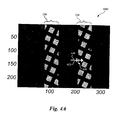
- FIGURE 4A is a diagram of a display area 300C which shows an enlarged portion of the exemplary workpiece and feature of FIGURE 3 and further illustrates a line tool that may used directly for determining the location of an edge point in the workpiece image, or that may underlie the operation of a box-type edge tool, as described further below.
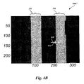
- FIGURE 4B is a diagram of the enlarged portion of FIGURE 4A after a morphology filter has been applied to the workpiece image. As shown in FIGURE 4B, in the display area 300C', the grid 304 has been effectively removed by the morphology filter, as will be described in more detail below.
- the display area 300C' may, or may not, be displayed to a user, in various embodiments. In any case, the diagram of the display area 300C' is useful, along with the diagram 300C of FIGURE 14A, in illustrating various aspects of the method of the present invention.
- FIG. 300C an "occluding feature avoiding" line tool 610 with a selector 612 is shown to be located over a valid edge portion 650, which is located at the left edge of the trace 330.
- the user selects the line tool 610 and drags it across the display to place the selector 612 as close as possible to the desired edge of the trace 330 at a valid edge portion 650 of the original unaltered image.
- a morphological filter described in greater detail below, is defined manually, semi-automatically, or automatically, and applied to remove the grid pattern 304 and produce the filtered image shown in FIGURE 4B.
- the morphological filter is determined or selected such that the displacement of the desired edge due to filtering is limited to, at most, several pixels. For example, in various embodiments, using known filtering techniques, it is reasonable to expect the edge displacement due to filtering to be on the order of 4-5 pixels or less.
- the displacement of the edge position in a filtered image depends on several factors, for example: mask size employed in the filter, orientation of filter relative to that of the edge to be detected, etc.
- the displacement may be on the order of 4 or 5 pixels or less, which is good enough for many applications.
- a 3x3 mask is used and the desired edge has a similar orientation to the filter mask, that is, they have boundaries that are almost parallel, resulting in an edge displacement of less than 1 pixel in this example.
- a dilation operation that replaces each pixel in the 3x3 mask region with the maximum pixel intensity in the mask region is applied to the image of FIGURE 4A for a number of iterations that is sufficient to remove the grid 304.
- the number of iterations that is sufficient depends on the maximum dimension of the occluding object features, e.g.- the dimension of the bars of the grid 304 along the direction of the filter.
- the grid bars are 10-15 pixels wide.
- their maximum dimension along the direction(s) of the simple 3x3 filter mask is significantly larger than their nominal width. Accordingly, 27 iterations of the 3x3 filter were applied to the image of FIGURE 4A to remove the grid 304.
- the same number of iterations of an erosion operation that replaces each pixel in the 3x3 mask region with the minimum pixel intensity in the mask region are then applied, to restore the edges in the filtered image approximately to their original positions.
- the occluding feature is generally lighter, that is, of higher image intensity, than the occluded features to be inspected, then the dilation and erosion operations described above will be performed in the reverse order to remove lighter occluding features.
- the line tool 610 is operable, in its ordinary mode of operation, on the filtered image shown in FIGURE 4B to roughly, that is, approximately, locate the desired edge of the circuit trace 330.
- the desired edge location is only approximate at this point because, as noted previously, the filtering process tends to alter the edge locations of the circuit traces 320 and 330 to an extent that is significant relative to precision measurment operations.
- the method then returns to the original unaltered image shown in FIGURE 4A, and for the roughly located edge point adjusts the operating parameters of the edge tool 610 to effectively relocate the selector at the determined location of the "filtered" edge point and to effectively shorten the length of the scan line of the line tool 610, such that edge detection is restricted to a close neighborhood of the roughly located edge point.
- the line tool 610 operates according to its ordinary edge detection processes, as described in more detail below, on the original image as shown in FIGURE 4A. The benefits of the foregoing set of operations are described with reference to FIGURES 5A and 5B.
- the line tool 610 then scans over data points (e.g., pixels) along its length with various operations.
- data points e.g., pixels
- the scanning over the data points to determine the edge locations is utilized in the method of the present invention for both the rough edge location performed on a filtered version of the image, and then again when the original image data is being evaluated for more precise locating of the edge points.
- the length of the scan lines finally utilized for the more precise edge locations in the original image data may be restricted for edge detection in a close neighborhood of the roughly located edge points, and thus finally utilized scan lines are generally made to be shorter than those utilized for the ordinary operation of the tool, and the rough edge location in the filtered image.
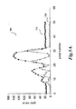
- FIGURE 5A is a diagram of a graph 700 showing image intensity (gray) values 725 obtained across the length of the line tool 610 in FIGURE 4A.
- FIGURE 5B is a diagram of a graph 700' showing filtered image intensity (gray) values 725' obtained across the line tool 610 in FIGURE 4B.
- the gradient magnitude values 726 and 726' derived from the intensity values 725 and 725' respectively, are also shown for reference in FIGURES 5A and 5B, respectively.
- the data points across the line tool 610 are referenced as pixel numbers from 0-50 along the horizontal axis. Beginning from data point 0, the image intensity values initially indicate a relatively darker region up to approximately data point 23, which is then followed by a relatively lighter region up to data point 50.
- the location of an edge in an image many algorithms find the edge location by locating the maximum gradient magnitude within the intensity data. If there are multiple gradients along the intensity data (e.g., as frequently occurs when the grid 304 has not been removed from the display area, as shown in FIGURE 5A, and as frequently occurs for the evaluation performed in the more precise edge location performed in the latter part of the method of the present invention), then the location of the selector 612 can help the algorithm determine which gradient corresponds to the desired edge. An indication (e.g., the orientation or direction of the tool 610) can also be provided for helping the algorithm determine whether it should be looking for a rising or a falling edge. In FIGURE 5B, the maximum gradient criterion clearly indicates that the edge point is located at approximately data point 23.
- FIGURE 5A the complex set of image intensity variations (edges) shown in FIGURE 5A, associated with the grid edges and other shadows in FIGURE 4A, are not present in the filtered image intensity values shown in FIGURE 5B.
- detection of the desired edge in the filtered image is both simple and reliable.
- a rising edge is also indicated, with reference to the direction of the line tool 610, as indicated by its arrowhead.
- the edge location (the maximum gradient location) is actually found with a sub-pixel level of precision, by finding the interpolated maximum gradient location, using known curve fitting techniques or known centroid finding techniques that identify the centroid of the area under the gradient curve that surrounds the maximum gradient value, or the like.
- various characteristics of the edge near pixel 23 are determined and stored, to facilitate an even more reliable selection and determination of the desired edge on a similar part, later, in run mode. Such characteristics may include the overall valley-to-peak intensity variation surrounding the edge, for example between the local minimum pixel 20 and the local maximum pixel 26 (or some proportion thereof); the nominal intensity value at the edge location; and/or a ratio between these two values, or the like.
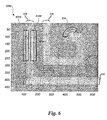
- FIGURE 6 is a diagram of a display area 300D which shows the exemplary workpiece and various features to be inspected of FIGURE 3 after morphological filtering, along with exemplary embodiments of GUI widgets representing box, arc and point tools for edge location superimposed on the filtered image in a manner analogous to that shown in FIGURE 4B, all usable in various embodiments of the systems and methods according to this invention.
- the display area 300D includes box tool widgets 810A and 810B, a line tool widget 820, and an arc tool widget 830.
- these video tools 810-830 are positioned on the original image by the user, used on the filtered image with predefined default settings, and finally used on the unfiltered original image.
- these settings are adjusted or redefined by a user, but need not be redefined in order to use the tool.
- the tools are employed with the alternative predefined selectable settings.
- edge detection tool GUI widgets are generally described in the QVPAK 3D CNC Vision Measuring Machine Users Guide and the QVPAK 3D CNC Vision Measuring Machine Operation Guide, which were previously incorporated herein by reference.
- the box tool widgets 810A and 810B are displayed as boxes with arrows along the side and a selector in the center.
- the box tool widgets 810A and 810B are sized, positioned and rotated by an operator, until the box is indicative of, or defines, the region of interest, and the arrow is indicative of an edge to be determined and inspected.
- the box tool widgets 810A and 810B generally use one or more conventional edge gradient(s) along the edge in the region of interest, and the edge is determined based on the location of the selector during a manual or training mode of operation and the local magnitudes of the edge gradient(s) along various scan lines, as outlined above.
- the direction of the arrow defines a reference direction or polarity to be associated with the edge gradient in these various exemplary embodiments. It should be appreciated that the extents of the region of interest indicated by the boundaries of the box tool widgets 810A and 810B are fully adjustable and rotatable, when desired.
- the line tool widget 820 operates as previously described for the line tool 610 of FIGURES 4A and 4B, while the arc tool widget 830 determines edge points defining a curve (e.g., a radius) for an image feature.
- both the arc tool widget 830 and the box tool widgets 810A and 810B include operations similar to those of the line tool widget 610 (or 820), in that the desired edge characteristics that are used throughout the region of interest of the box tool are determined based on an initial scan line which coincides with the location of the selector just as for the line tool 610, as described above.
- the user must locate the selector along a valid edge portion, such as the valid edge portion 650 previously described with reference to FIGURE 4A.
- the operation of the box tool widgets 810A and 810B and the arc tool widget 830 then consist of the use of multiple scan lines, as though each were an instance of a line tool (such as the line tool 610), with the operable edge screening parameters (in addition to the maximum gradient criterion) for all scan lines being those determined along the single scan line corresponding to the selector during the learn/training/teach mode.
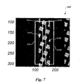
- FIGURE 7 is a diagram of a display area 300E which shows an enlarged portion of the display area of FIGURE 6 further illustrating the box tool widgets 810A and 810B.
- the box tool widgets 810A and 810B include orientation arrows 912A and 912B that correspond to the orientation arrowhead of the line tool 610.
- the selectors 914A and 914B operate similarly to the selector portion 612 of the line tool 610, and respectively govern the operations of a respective initial scan line that is used for determining various edge parameters used throughout the region of interest of the respective box tool, as described above.
- a box tool widget may include a feature that allows the user "request” one or more additional selectors, and position them at additional positions along valid edge portions. Then corresponding edge parameters determined based on the plurality of scan lines associated with the plurality of selectors may be averaged, or otherwise appropriately combined. Such averaging will make the learned edge parameters less susceptible to potential local variations along the edge in the region of interest. Thus, operation of such a box tool is likely to be more robust.
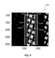
- FIGURE 8 is a diagram of the display area 300E of FIGURE 7, further illustrating the operation of the box tools 810A and 810B using multiple scan lines but effectively avoiding or masking the effects of the occluding grid 304.
- Various considerations for such scan lines may include the spacing, secondary scan line qualifications (e.g., the number of continuous pixels is a scan line), and other factors.
- the spacing of the scan lines may be programmable either as a customizable default, or can be determined in each instance, in some cases utilizing a mechanism such as a user utilizing a sub-menu to alter the spacing.
- any candidate edge along any scan line must also match the edge parameters determined during training or learn mode for the known valid edge along the initial scan line that coincides with the selector at training or learn mode time. This effectively eliminates any edges associated with occluding features, shadows, or the like.
- FIGURE 9 is a flow diagram illustrating one exemplary embodiment of a routine 1100 for creating and using a part program to inspect a workpiece having a region of interest.
- a part program is created which is usable to inspect the portion of the workpiece having the region of interest.
- the created part program is run.
- a number of workpieces that are similar to the first workpiece are inspected using the part program.
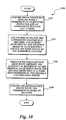
- FIGURE 10 is a flow diagram illustrative of one exemplary embodiment of a routine 1200 for inspecting a workpiece feature that is occluded by an extraneous feature in accordance with the present invention.
- an image is acquired which may include both the occluded workpiece feature to be inspected and the extraneous occluding feature (e.g., a grid).
- filters e.g., morphology filters
- edge detection is performed on the filtered image so as to roughly locate the edge points of the workpiece feature.
- the morphology filters that are used may be closing or opening with a 3 ⁇ 3 square mask or a 5 ⁇ 5 disc mask.
- the method can be performed in a relatively expedient manner.
- the accuracy of the edge location is improved by returning to the original unfiltered image and doing edge detection in a close neighborhood of the roughly located edge points.
- the refined edge points are utilized to fit, inspect and/or locate the workpiece feature.
- the routine 1200 of FIGURE 10 is usable in both a training mode and in a run mode.
- a general box tool, and/or other such efficient multi-point tools can be generally positioned over a region which includes both the occluded feature (e.g., a workpiece feature) and the occluding feature (e.g., a grid).
- the user is allowed to employ such more-efficient multi-point tools in their normal manner, without special consideration of the occluding features which may be present.
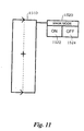
- FIGURE 11 shows an exemplary embodiment of a box tool GUI widget 1510, along with an exemplary embodiment of a control widget 1520 usable to select a mask mode that effectively avoids occluding feature edges during operations associated with edge detection according to this invention, in a training mode or manual mode of machine operation.
- the "mask mode" may be associated with the methods of the present invention in that when a mask mode is selected, the method for measuring occluded features using various operations outlined above is utilized.
- the control widget 1520 includes an on button 1522 and an off button 1524.
- control widget 1520 When the on button 1522 is clicked on with a mouse or is otherwise actuated, it initiates automatic operations such that a method for measuring occluded features such as that illustrated by the routine 1200 of FIGURE 10 is performed.
- Other tools may be provided with similar control widgets 1520.
- the control widget 1520 can be represented in many other forms, divided, included within more complex multi-fimction widgets, or included directly within a video tool representation, or the like.
- the essential aspect of the widget 1520 is that it is usable to activate or deactivate an operating mode for measuring occluded features such as that illustrated by the routine 1200 according to this invention.
- a demonstration mode related to the measuring of occluded features may be provided.
- a control widget 1520 may be clicked on with a mouse or otherwise actuated to initiate automatic operations that provide a learn or training mode demonstration that displays the filtered image for evaluation, and/or previews or mimics the results of comparable run mode operations, or the like, for example as will be described in more detail below.
- Such a demonstration may be evaluated by a machine operator to confirm or reject its efficacy and the associated programming parameters or instructions.
- a control widget 1520 may be clicked on with a mouse or otherwise actuated to accept the settings of a fully defined or trained measuring of occluded features operation, for example, or to bypass a training mode demonstration, or to accept the results indicated by an evaluation image provided as a result of a training mode demonstration, in order to move on to additional training mode operations.
- the operation of a control widget 1520 may depend on whether there is a higher level or background command in effect, that has already set the machine in a mode for measuring occluded features according to this invention.
- such a mode may be appropriate when an extraneous feature covers most or all of an image including multiple features or regions to be inspected (e.g., the repetitive grid pattern 304, or the like).
- an extraneous feature covers most or all of an image including multiple features or regions to be inspected (e.g., the repetitive grid pattern 304, or the like).
- various aspects of the previously described tools and widgets may be implemented separately or in various combinations.
- alternative forms of the various GUI widgets and controls are apparent. Therefore, the foregoing embodiments are intended to be illustrative only, and not limiting.
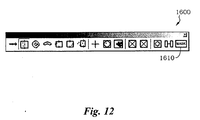
- FIGURE 12 illustrates one exemplary embodiment of a graphical user interface toolbar window 1600 which includes a mask mode selector 1610 usable for selecting a mode for measuring occluded features according to this invention.
- the remainder of the toolbar window 1600 is similar to that provided in the QVPAKTM software discussed above.
- the mask mode selector 1610 which is used for selecting the mode for measuring occluded features may be dragged onto an image for a global mask mode or onto an individual tool for a tool-specific mask mode.
- the tools may have widgets that reflect when they are in a mask mode.
- the mask mode selector 1610 may remain on the toolbar 1600 and provides a toggling function.
- a video tool When the mask mode selector 1610 is toggled on, a video tool is dragged off of the tool bar 1600 and is in a mask mode, and may be provided with a visual feature that indicates that it is in the mask mode.
- the user interface is be able to support a semi-automatic method of the measuring of occluded features mode, in which case when the mask mode is activated, the tool may query the user to select the semi-automatic technique, or displays an example of the results of several alternatives for the user to select from.
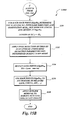
- FIGURE 13 is a flow diagram illustrative of one exemplary embodiment of a routine 1700 for performing learn mode operations with reference to a mask mode widget.
- the learn/training/teach mode is entered.
- one or more operations are provided that are usable to measure occluded features during the mask mode.
- a mask mode activation/deactivation widget (as described in FIGURES 11 and 12) is provided that is usable to set the mode in the region of interest.
- the image is acquired.
- the tool is set up for training.
- a determination is made as to whether the mask mode has been selected. If the mask mode has not been selected, then the routine continues to a block 1740, where the tool is trained without the occluded feature measuring method. If the mask mode has been selected, then the routine continues to a block 1730, where an occluded feature learn/train/teach mode is performed, as will be described in more detail below with respect to FIGURE 14.
- the routine continues to a block 1742, where the results of the trained tool operations are displayed.
- a decision block 1744 a determination is made as to whether the current results of the trained tool are acceptable (e.g. was the expected edge found, is its location approximately as expected, etc.). If the current results are not acceptable, then the routine returns to block 1722. If the current results are acceptable, then the routine continues to a decision block 1746.
- FIGURES 14A-14C are flow diagrams illustrative of one exemplary embodiment of a routine 2000, labeled as portions 2000A-2000C in FIGURES 14A-14C, respectively, for performing an occluded feature determination in learn/train/teach mode.
- the routine 2000 is performed at the block 1730 of FIGURE 13.
- the routine 2000 is performed at a block 2014, within the image IMG0 and the tool that is drawn in the GUI where the region of interest (ROI) is determined, the user selects a point P0 in the boundary of the feature to measure.
- the scan line SL0 is determined using the point P0 and the region of interest.
- the length of the scan line SL0 is represented by the variable SLO_LENGTH.
- the user selects parameters for the morphology filter F0 to use, including closing or opening and mask type and size.
- “closing” is utilized for a bright feature on a dark background and “opening” is utilized for a dark feature on a bright background.
- the mask type may be selected to be a 3 x 3 square or a 5 x 5 disk.
- a determination is made as to whether the user has selected an automatic option for determining the number of iterations. If the user does select the automatic option, then the routine continues to a block 2022, where the user enters the dimension of the grid D0 from which the number of iterations N0 is automatically determined. If the user does not select the automatic option, then the routine continues to a block 2024, where the user enters the number of iterations N0 to apply for the filter F0. The routine then continues to a point A that is continued in FIGURE 14B.
- the routine continues from point A to a block 2030, where the filter F0 is applied to the image IMG0 in the region of interest for the number of iterations N0. This produces the filtered image IMG1.
- edge detection is performed using the scan line SL0 in the filtered image IMG1.
- a decision block 2034 a determination is made as to whether an edge point has been detected. If no edge point has been detected, then the routine continues to a block 2036, where the edge detection process is halted, and the routine continues to a point C, which returns to block 2014 in FIGURE 14A, where the user may select another point P0 in the boundary so as to attempt to retry the edge detection process.
- the routine continues to a block 2038 where the edge detection parameters EDP0 are learned, including TH, THR, and THS, after which the routine continues to a point B which is continued in FIGURE 14C.
- the edge detection parameters for the edge threshold, it may be static (wherein the thresholds are not updated at run time) or dynamic (for which the thresholds are updated at run time).
- the threshold TH is a static image intensity threshold, which is used for a first localization or screening of the edge.
- the threshold THS is an edge strength threshold, that is, a variation of image intensity across the edge, which is used as a further localization or screening of the edge.
- the threshold THR is a dynamic threshold, that is a ratio based on TH and THS, which may be used to update the TH and THS thresholds at run time to compensate for overall intensity changes in the image, due lighting or workpiece finish variations, for example.
- a new scan line SL1 is determined which has the same direction and placement of the original scan line SL0, but shorter.
- the goal of using a shorter scan line is to analyze a small neighborhood of the potential edge point.
- a short scan line of a length of twenty-one pixels may initially be utilized.
- edge detection is performed using the scan line SL1 and the original image IMG0.
- a determination is made as to whether an edge point has been detected.
- the routine continues to a block 2056, where the edge detection process is halted, and the routine continues to a point C which returns to block 2014 of FIGURE 14A, where the user may select another point in the boundary to restart the edge detection process. If at block 2054 an edge point is detected, then the routine continues to a block 2058 where the edge detection parameters EDP1 are learned, including TH, THR, and THS.
- the length of the scan line SL1 that is determined at block 2050 is critical because it is part of the process to determine if a potential edge point is kept or discarded.
- the length determination may be done as a constant, or the initial constant length may be modified by analysis of the scan line. For example, if it is a rising edge, then the scan line should have dark pixels followed by bright pixels. If it does not, then pixels that do not follow this pattern should be discarded.
- a 2-dimensional analysis of each potential edge point may be performed to decide if the edge point is kept or discarded.
- FIGURES 15A and 15B are flow diagrams illustrative of one exemplary embodiment of a routine 2100 for executing an occluded feature run mode.
- the image IMG0 is read/acquired.
- the filter F0 (which was selected during the learn mode of FIGURE 14A) is applied to the input image IMG0 on the region of interest ROI so as to obtain the filtered image IMG1.
- the filter F0 and its parameters were determined during the learn mode of FIGURES 14A and 14B.
- edge detection is performed on the filtered image IMG1 on the scan lines SL i using the edge detection parameters EDP0 that were determined during the learn mode of FIGURES 14A and 14B.
- a scan line SL' k is determined with the same direction and orientation as the scan line SL k , but shorter and with a center at the edge point EdgePts k .
- the length of the scan line SL' k is generally less than the length of the scan line SL k .
- edge detection is applied on the original image IMG0 on the scan lines SL' k using the edge detection parameters EDP1 that were determined during the learn mode of FIGURE 14C.
- the edge points EdgePts kk are used to fit the feature to measure (e.g., line, circle, arc, etc.).
- outlier edge points are removed.
- An outlier removal process is the following:
- OUTLIER_THRESHOLD The value of OUTLIER_THRESHOLD is important, because it represents the outlier removal strength. The smaller the value of OUTLIER_THRESHOLD, the more points are likely to be removed. There are different ways to determine OUTLIER_THRESHOLD. One common way is to determine the gaussian distribution characteristics of the errors of all the data points (see step 2, above) and then multiply the standard deviation of the distribution by a desired number and set the outlier limits at the mean of the distribution plus and minus this value. A commonly used value is 2 times the standard deviation, such that a data point is considered an outlier if its error is higher than the error of 95.45% of all the points.
- the length of the scan line determined at block 2130 is important in various embodiments because it is part of the process to restrict potential edge points.
- different scan lines on the tool may be provided with different lengths (some scan lines will be placed close to the grid and, therefore, should be short in order to avoid having an edge correspond to the grid).
- the length determination may be done as a constant, or the initial constant length can be modified by analysis of the scan line. For example, if it is a rising edge, then the scan line should have dark pixels followed by bright pixels, and if it does not, then pixels that do not follow this pattern should be discarded at the end of the scan line.
- several criteria can be utilized to determine whether a potential edge point will be kept.
- edge detection parameters EDP1 an edge point will not be detected if it does not satisfy the strength THS of EDP1.
- Another criteria that may be utilized is an analysis of the neighbor pixels in the scan line or in the 2-dimensional neighborhood.
- a robustness criterion can be added to the tool to define the "acceptance strength" for a potential edge point to be kept as a good edge point.
- the methods of the present invention provide for simple operation by a user, in that standardized types of video tools may be utilized, rather than requiring customized operations.
- a user is not required to utilize scripting languages for implementing customized operations.
- the system allows for the use of pre-programmed icons and the like that even an unskilled user is able to use with minimal training.
- the region of interest is able to encompass both the occluded and occluding features. Thus, the user is not required to place individual point tools over all of the desired occluded feature regions.
Landscapes
- Engineering & Computer Science (AREA)
- Computer Vision & Pattern Recognition (AREA)
- Physics & Mathematics (AREA)
- General Physics & Mathematics (AREA)
- Theoretical Computer Science (AREA)
- Multimedia (AREA)
- Quality & Reliability (AREA)
- Image Processing (AREA)
- Image Analysis (AREA)
- Length Measuring Devices By Optical Means (AREA)
Applications Claiming Priority (1)
| Application Number | Priority Date | Filing Date | Title |
|---|---|---|---|
| US10/903,714 US7522763B2 (en) | 2004-07-30 | 2004-07-30 | Method of measuring occluded features for high precision machine vision metrology |
Publications (3)
| Publication Number | Publication Date |
|---|---|
| EP1622082A2 true EP1622082A2 (fr) | 2006-02-01 |
| EP1622082A3 EP1622082A3 (fr) | 2007-09-19 |
| EP1622082B1 EP1622082B1 (fr) | 2012-05-30 |
Family
ID=34937903
Family Applications (1)
| Application Number | Title | Priority Date | Filing Date |
|---|---|---|---|
| EP05016124A Ceased EP1622082B1 (fr) | 2004-07-30 | 2005-07-25 | Procédé de mesurer des marques cachées pour la métrologie de vision automatique à haute précision |
Country Status (4)
| Country | Link |
|---|---|
| US (1) | US7522763B2 (fr) |
| EP (1) | EP1622082B1 (fr) |
| JP (1) | JP4738925B2 (fr) |
| CN (1) | CN1904545B (fr) |
Cited By (1)
| Publication number | Priority date | Publication date | Assignee | Title |
|---|---|---|---|---|
| EP2375375A1 (fr) * | 2010-03-29 | 2011-10-12 | AnMo Electronics Corporation | Produit de programme informatique lié à des opérations d'analyse d'image numérique |
Families Citing this family (26)
| Publication number | Priority date | Publication date | Assignee | Title |
|---|---|---|---|---|
| US8352400B2 (en) | 1991-12-23 | 2013-01-08 | Hoffberg Steven M | Adaptive pattern recognition based controller apparatus and method and human-factored interface therefore |
| US7904187B2 (en) | 1999-02-01 | 2011-03-08 | Hoffberg Steven M | Internet appliance system and method |
| US7583852B2 (en) * | 2004-10-26 | 2009-09-01 | Mitutoyo Corporation | Method of filtering an image for high precision machine vision metrology |
| US7567713B2 (en) * | 2006-02-08 | 2009-07-28 | Mitutoyo Corporation | Method utilizing intensity interpolation for measuring edge locations in a high precision machine vision inspection system |
| US20090073448A1 (en) * | 2007-09-18 | 2009-03-19 | Asml Netherlands B.V. | Method of measuring the overlay error, an inspection apparatus and a lithographic apparatus |
| US8269830B1 (en) | 2011-04-14 | 2012-09-18 | Mitutoyo Corporation | Inspecting potentially interfering features in a machine vision system |
| TWI457008B (zh) * | 2011-10-13 | 2014-10-11 | Acer Inc | 立體音效裝置、立體音效系統以及立體音效播放方法 |
| US8989511B1 (en) * | 2012-06-28 | 2015-03-24 | Western Digital Technologies, Inc. | Methods for correcting for thermal drift in microscopy images |
| JP5947169B2 (ja) * | 2012-09-14 | 2016-07-06 | 株式会社キーエンス | 外観検査装置、外観検査法およびプログラム |
| US9177222B2 (en) * | 2012-11-05 | 2015-11-03 | Mitutoyo Corporation | Edge measurement video tool and interface including automatic parameter set alternatives |
| JP6015477B2 (ja) * | 2013-02-07 | 2016-10-26 | 株式会社島津製作所 | 外観検査方法及び外観検査装置 |
| US10477154B2 (en) | 2013-03-07 | 2019-11-12 | Cognex Corporation | System and method for aligning two work pieces with a vision system in the presence of occlusion |
| US9934611B2 (en) * | 2013-09-11 | 2018-04-03 | Qualcomm Incorporated | Structural modeling using depth sensors |
| CN103886313A (zh) * | 2014-04-03 | 2014-06-25 | 哈尔滨天源石化装备制造有限责任公司 | 一种加油站车牌定位方法 |
| CN104792263B (zh) | 2015-04-20 | 2018-01-05 | 合肥京东方光电科技有限公司 | 确定显示母板的待检测区域的方法和装置 |
| CN107144210B (zh) * | 2017-04-25 | 2019-10-29 | 中国科学院微电子研究所 | 一种电子显微图像线条宽度和粗糙度的测量方法 |
| TWI787296B (zh) * | 2018-06-29 | 2022-12-21 | 由田新技股份有限公司 | 光學檢測方法、光學檢測裝置及光學檢測系統 |
| CN109297496A (zh) * | 2018-09-29 | 2019-02-01 | 上海新世纪机器人有限公司 | 基于slam的机器人定位方法及装置 |
| CN109166506A (zh) * | 2018-10-31 | 2019-01-08 | 苏州旷视智能科技有限公司 | 基于高精度机器视觉的显示面板的检测方法 |
| US11150200B1 (en) | 2020-06-15 | 2021-10-19 | Mitutoyo Corporation | Workpiece inspection and defect detection system indicating number of defect images for training |
| US11430105B2 (en) | 2020-06-15 | 2022-08-30 | Mitutoyo Corporation | Workpiece inspection and defect detection system including monitoring of workpiece images |
| CN112861873B (zh) * | 2021-01-05 | 2022-08-05 | 杭州海康威视数字技术股份有限公司 | 一种具有烟盒的图像的处理方法 |
| CN115359080A (zh) * | 2021-05-17 | 2022-11-18 | 梅特勒-托利多(常州)测量技术有限公司 | 一种防人员干扰的物品体积测量方法 |
| US20230035601A1 (en) * | 2021-07-28 | 2023-02-02 | OPAL AI Inc. | Floorplan Generation System And Methods Of Use |
| US11756186B2 (en) | 2021-09-15 | 2023-09-12 | Mitutoyo Corporation | Workpiece inspection and defect detection system utilizing color channels |
| CN118486445A (zh) * | 2024-07-15 | 2024-08-13 | 江西为易科技有限公司 | 基于图像识别的ai智能医疗监管系统 |
Family Cites Families (11)
| Publication number | Priority date | Publication date | Assignee | Title |
|---|---|---|---|---|
| EP0731956A4 (fr) * | 1993-11-30 | 1997-04-23 | Arch Dev Corp | Procede et systeme automatises destines a l'alignement et a la correlation d'images obtenues selon deux techniques d'imagerie differentes |
| US5579445A (en) * | 1993-12-17 | 1996-11-26 | Xerox Corporation | Image resolution conversion method that employs statistically generated multiple morphological filters |
| US5796868A (en) * | 1995-12-28 | 1998-08-18 | Cognex Corporation | Object edge point filtering system for machine vision |
| US6542180B1 (en) * | 2000-01-07 | 2003-04-01 | Mitutoyo Corporation | Systems and methods for adjusting lighting of a part based on a plurality of selected regions of an image of the part |
| US6563324B1 (en) * | 2000-11-30 | 2003-05-13 | Cognex Technology And Investment Corporation | Semiconductor device image inspection utilizing rotation invariant scale invariant method |
| US6627863B2 (en) * | 2000-12-15 | 2003-09-30 | Mitutoyo Corporation | System and methods to determine the settings of multiple light sources in a vision system |
| JP4199939B2 (ja) * | 2001-04-27 | 2008-12-24 | 株式会社日立製作所 | 半導体検査システム |
| US7003161B2 (en) * | 2001-11-16 | 2006-02-21 | Mitutoyo Corporation | Systems and methods for boundary detection in images |
| CN1442246A (zh) * | 2002-03-06 | 2003-09-17 | 昆明利普机器视觉工程有限公司 | 数字视频轧钢带宽检测系统 |
| US20050031191A1 (en) * | 2003-08-04 | 2005-02-10 | Mitutoyo Corporation | Methods and apparatus for inspection of lines embedded in highly textured material |
| AU2003258084A1 (en) * | 2003-08-04 | 2005-03-07 | Grass Valley (U.S.) Inc. | Apparatus and method for reducing noise in an image |
-
2004
- 2004-07-30 US US10/903,714 patent/US7522763B2/en active Active
-
2005
- 2005-07-20 JP JP2005210588A patent/JP4738925B2/ja not_active Expired - Fee Related
- 2005-07-25 EP EP05016124A patent/EP1622082B1/fr not_active Ceased
- 2005-07-29 CN CN2005100876740A patent/CN1904545B/zh not_active Expired - Fee Related
Non-Patent Citations (2)
| Title |
|---|
| "QVPAK 3D CNC VISION MEASURING MACHINE OPERATION GUIDE", September 1996 |
| "QVPAK 3D CNC VISION MEASURING MACHINE USERS GUIDE", January 2003 |
Cited By (2)
| Publication number | Priority date | Publication date | Assignee | Title |
|---|---|---|---|---|
| EP2375375A1 (fr) * | 2010-03-29 | 2011-10-12 | AnMo Electronics Corporation | Produit de programme informatique lié à des opérations d'analyse d'image numérique |
| US8358851B2 (en) | 2010-03-29 | 2013-01-22 | Anmo Electronics Corporation | Digital image analyzing method and related computer program product |
Also Published As
| Publication number | Publication date |
|---|---|
| JP2006048675A (ja) | 2006-02-16 |
| EP1622082A3 (fr) | 2007-09-19 |
| JP4738925B2 (ja) | 2011-08-03 |
| CN1904545A (zh) | 2007-01-31 |
| EP1622082B1 (fr) | 2012-05-30 |
| CN1904545B (zh) | 2011-04-13 |
| US7522763B2 (en) | 2009-04-21 |
| US20060023937A1 (en) | 2006-02-02 |
Similar Documents
| Publication | Publication Date | Title |
|---|---|---|
| EP1622082A2 (fr) | Procédé de mesurer des marques cachées pour la métrologie de vision automatique à haute précision | |
| US7394926B2 (en) | Magnified machine vision user interface | |
| US7769222B2 (en) | Arc tool user interface | |
| CN1699916B (zh) | 从由机器视觉检查系统执行的检查操作中排除无关特征的系统和方法 | |
| US7454053B2 (en) | System and method for automatically recovering video tools in a vision system | |
| EP1653407A2 (fr) | Méthode de filtrage d'image pour une machine de métrologie visuelle de haute précision | |
| US7627162B2 (en) | Enhanced video metrology tool | |
| US7570795B2 (en) | Multi-region autofocus tool and mode | |
| JP6243705B2 (ja) | 自動パラメータ設定選択肢を含むエッジ測定ビデオツール及びインタフェース | |
| US20130027538A1 (en) | Multi-region focus navigation interface | |
| US8269830B1 (en) | Inspecting potentially interfering features in a machine vision system | |
| US8917940B2 (en) | Edge measurement video tool with robust edge discrimination margin | |
| JP6293453B2 (ja) | エッジ測定ビデオツールパラメータ設定ユーザインタフェース |
Legal Events
| Date | Code | Title | Description |
|---|---|---|---|
| PUAI | Public reference made under article 153(3) epc to a published international application that has entered the european phase |
Free format text: ORIGINAL CODE: 0009012 |
|
| AK | Designated contracting states |
Kind code of ref document: A2 Designated state(s): AT BE BG CH CY CZ DE DK EE ES FI FR GB GR HU IE IS IT LI LT LU LV MC NL PL PT RO SE SI SK TR |
|
| AX | Request for extension of the european patent |
Extension state: AL BA HR MK YU |
|
| PUAL | Search report despatched |
Free format text: ORIGINAL CODE: 0009013 |
|
| AK | Designated contracting states |
Kind code of ref document: A3 Designated state(s): AT BE BG CH CY CZ DE DK EE ES FI FR GB GR HU IE IS IT LI LT LU LV MC NL PL PT RO SE SI SK TR |
|
| AX | Request for extension of the european patent |
Extension state: AL BA HR MK YU |
|
| 17P | Request for examination filed |
Effective date: 20080219 |
|
| 17Q | First examination report despatched |
Effective date: 20080320 |
|
| AKX | Designation fees paid |
Designated state(s): DE FR GB IT |
|
| GRAP | Despatch of communication of intention to grant a patent |
Free format text: ORIGINAL CODE: EPIDOSNIGR1 |
|
| GRAS | Grant fee paid |
Free format text: ORIGINAL CODE: EPIDOSNIGR3 |
|
| GRAA | (expected) grant |
Free format text: ORIGINAL CODE: 0009210 |
|
| AK | Designated contracting states |
Kind code of ref document: B1 Designated state(s): DE FR GB IT |
|
| REG | Reference to a national code |
Ref country code: GB Ref legal event code: FG4D |
|
| REG | Reference to a national code |
Ref country code: DE Ref legal event code: R096 Ref document number: 602005034380 Country of ref document: DE Effective date: 20120802 |
|
| PLBE | No opposition filed within time limit |
Free format text: ORIGINAL CODE: 0009261 |
|
| STAA | Information on the status of an ep patent application or granted ep patent |
Free format text: STATUS: NO OPPOSITION FILED WITHIN TIME LIMIT |
|
| 26N | No opposition filed |
Effective date: 20130301 |
|
| REG | Reference to a national code |
Ref country code: DE Ref legal event code: R097 Ref document number: 602005034380 Country of ref document: DE Effective date: 20130301 |
|
| REG | Reference to a national code |
Ref country code: FR Ref legal event code: PLFP Year of fee payment: 12 |
|
| REG | Reference to a national code |
Ref country code: FR Ref legal event code: PLFP Year of fee payment: 13 |
|
| REG | Reference to a national code |
Ref country code: FR Ref legal event code: PLFP Year of fee payment: 14 |
|
| PGFP | Annual fee paid to national office [announced via postgrant information from national office to epo] |
Ref country code: IT Payment date: 20220726 Year of fee payment: 18 Ref country code: GB Payment date: 20220720 Year of fee payment: 18 Ref country code: DE Payment date: 20220620 Year of fee payment: 18 |
|
| PGFP | Annual fee paid to national office [announced via postgrant information from national office to epo] |
Ref country code: FR Payment date: 20220720 Year of fee payment: 18 |
|
| REG | Reference to a national code |
Ref country code: DE Ref legal event code: R119 Ref document number: 602005034380 Country of ref document: DE |
|
| GBPC | Gb: european patent ceased through non-payment of renewal fee |
Effective date: 20230725 |
|
| PG25 | Lapsed in a contracting state [announced via postgrant information from national office to epo] |
Ref country code: DE Free format text: LAPSE BECAUSE OF NON-PAYMENT OF DUE FEES Effective date: 20240201 Ref country code: GB Free format text: LAPSE BECAUSE OF NON-PAYMENT OF DUE FEES Effective date: 20230725 |
|
| PG25 | Lapsed in a contracting state [announced via postgrant information from national office to epo] |
Ref country code: FR Free format text: LAPSE BECAUSE OF NON-PAYMENT OF DUE FEES Effective date: 20230731 |
|
| PG25 | Lapsed in a contracting state [announced via postgrant information from national office to epo] |
Ref country code: IT Free format text: LAPSE BECAUSE OF NON-PAYMENT OF DUE FEES Effective date: 20230725 |