EP1621908A1 - Boitier de distribution de câbles optiques - Google Patents
Boitier de distribution de câbles optiques Download PDFInfo
- Publication number
- EP1621908A1 EP1621908A1 EP05106800A EP05106800A EP1621908A1 EP 1621908 A1 EP1621908 A1 EP 1621908A1 EP 05106800 A EP05106800 A EP 05106800A EP 05106800 A EP05106800 A EP 05106800A EP 1621908 A1 EP1621908 A1 EP 1621908A1
- Authority
- EP
- European Patent Office
- Prior art keywords
- optical
- permutation
- rack
- cables
- permutation device
- Prior art date
- Legal status (The legal status is an assumption and is not a legal conclusion. Google has not performed a legal analysis and makes no representation as to the accuracy of the status listed.)
- Granted
Links
- 230000003287 optical effect Effects 0.000 title claims abstract description 65
- 239000013307 optical fiber Substances 0.000 claims abstract description 19
- 239000011159 matrix material Substances 0.000 claims description 14
- 238000006073 displacement reaction Methods 0.000 description 1
- 239000000835 fiber Substances 0.000 description 1
- 230000037431 insertion Effects 0.000 description 1
- 238000003780 insertion Methods 0.000 description 1
Images

Classifications
-
- H—ELECTRICITY
- H04—ELECTRIC COMMUNICATION TECHNIQUE
- H04Q—SELECTING
- H04Q1/00—Details of selecting apparatus or arrangements
- H04Q1/02—Constructional details
- H04Q1/09—Frames or mounting racks not otherwise provided for
-
- G—PHYSICS
- G02—OPTICS
- G02B—OPTICAL ELEMENTS, SYSTEMS OR APPARATUS
- G02B6/00—Light guides; Structural details of arrangements comprising light guides and other optical elements, e.g. couplings
- G02B6/44—Mechanical structures for providing tensile strength and external protection for fibres, e.g. optical transmission cables
- G02B6/4439—Auxiliary devices
- G02B6/444—Systems or boxes with surplus lengths
- G02B6/4452—Distribution frames
- G02B6/44526—Panels or rackmounts covering a whole width of the frame or rack
-
- H—ELECTRICITY
- H04—ELECTRIC COMMUNICATION TECHNIQUE
- H04Q—SELECTING
- H04Q2201/00—Constructional details of selecting arrangements
- H04Q2201/08—Pivotable parts
-
- H—ELECTRICITY
- H04—ELECTRIC COMMUNICATION TECHNIQUE
- H04Q—SELECTING
- H04Q2201/00—Constructional details of selecting arrangements
- H04Q2201/10—Housing details
-
- H—ELECTRICITY
- H04—ELECTRIC COMMUNICATION TECHNIQUE
- H04Q—SELECTING
- H04Q2201/00—Constructional details of selecting arrangements
- H04Q2201/80—Constructional details of selecting arrangements in specific systems
- H04Q2201/804—Constructional details of selecting arrangements in specific systems in optical transmission systems
Definitions
- the present invention refers to an optical permutation device.
- the present invention refers to a passive optical permutation device, in which a plurality of entering optical fibres are connected with a plurality of exiting optical fibres.
- An optical supply unit comprises a plurality of optical apparatuses, each having preferably a plurality of incoming and exiting optical signals.
- optical permutation devices are used which allow, by means of a plurality of connectors, to connect with each other the different signals coming from the various apparatuses.
- said permutation devices are placed inside the box having a side devoted to connection, which side receives the optical fibres entering and exiting from the optical apparatuses to be connected with each other, and a side devoted to permutations, in which the fibres coming from the various apparatuses are connected with each other, according to a predetermined scheme, by means of optical fibre segments of predetermined length (U-bolts).
- the two sides must be separated from each other to avoid confusion among the fibres that come from the various apparatuses, which fibres are all positioned on one side of the box, and the segments of fibres used for making connections, all positioned on the other side of the box.
- the side on which the connection is operated is the rear side of the box, since said connections are generally operated only once, that is when the permuter is settled.
- the front side of the box usually presents the connectors and the segments of fibres suitable for effecting permutations among the fibres of the number of apparatuses.
- the applicant has realized an optical permutation device having a box structure, in which it is possible to make connection and permutation connections on optical fibres arriving at said permutation device operating on the same side of the box, even though the connection side and the permutation side of the box are physically separated.
- An aspect of the present invention refers to an optical permutation device, comprising a box structure, formed by a box element closable by means of a rotatable shutter, having at least a hollow able to allow the entrance and exit of optical fibre cables of optical apparatuses to be connected with each other according to a predetermined scheme, characterized in that it comprises a rotatable separating closing rack, in which on the first side are displaced connectors for connection of said optical fibre cables to the permuter and on the second opposite side are displaced the permutation connectors devoted to optically connect said entering and exiting cables to each other of said optical apparatuses according to a predetermined scheme.
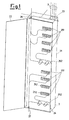
- the optical permutation device comprises a box structure 2 in which a plurality of cables and optical fibres 3 are inserted.
- the box structure is preferably placed in optical units comprising a plurality of optical apparatuses having respectively incoming and exiting optical fibres and it is used to connect said apparatuses with each other according to a predetermined scheme.
- the box structure is substantially provided with a box element 21 closable by means of a rotatable shutter 22.
- a box element 21 closable by means of a rotatable shutter 22.
- an opening 23 is provided to allow the entrance and exit of the optical fibre cables of said optical apparatuses.
- said box structure comprises a rotatable rack 24, in-between the box element 23 and the rotatable closing shutter, which substantially turns around the same rotation axis of the rotatable shutter 22, which sizes allow it to be inserted within said box element.
- Said rack shows a first side, the so called “connection side” preferably facing the box element, in which are connected the entering and exiting optical fibres of said optical apparatuses coming from the opening 23 and a second side, the so called “permutation side”, preferably facing the outer box structure.
- the rack on said connection side comprises a plurality of connection matrixes 241, each provided with a plurality of clamps 242, each able to receive at least one optical connector.
- the rack can also have only one matrix or a number of matrixes higher than that shown in the illustrative figure.
- the number of clamps for each matrix can vary from a minimum of a single clamp to a maximum of a predetermined number of clamps for each row of the matrix.
- connection side comprises at least a first device for lodgement 243 of exceeding optical fibres, on which segments of optical fibre cables coming from said opening 23 of the optical apparatuses can be rolled-up.
- connection side comprises a plurality of housings 244 able to movably receive a casing for an optical joint between the end of said optical fibre cable and one segment of fibre provided at one end with a connector insertable in at least one of said clamps.
- the permutation side comprises a plurality of permutation matrixes 251 each provided with a plurality of clamps 252, each able to receive at least one optical connector.
- Such permutation matrixes are optically connected with the connection matrixes displaced on the connection side of the rack.
- each clamp of the permutation matrix 252 is connected with a clamp 242 of the connection matrix 241.
- the connection among the clamps of the two sides is operated in a way that the configuration of the matrixes on the connection side is the same of the permutation side.
- the rack comprises a first passing hollow 26, preferably realized in correspondence with the top hinge of the rotatable rack, and a second passing hollow 27 preferably realized in correspondence with the bottom hinge of the rotatable rack.
- the permutation side comprises at least a second device for lodgement 243 of exceeding optical fibres, on which optical fibres cables can be rolled up.
- two operation phases on the optical permutation device can be individuated according to the present invention.
- a first phase of setting-up of the permutation device which comprises the connection phase, in which the optical cables of the optical apparatuses to be connected with each other, are connected with the rack in the connection side, through the insertion of optical connectors in the above clamps and/or through the realization of optical joints.
- the rack is preferably rotated towards the abovementioned "opening" direction, in a way that the operator can easily make the established connections.
- the rack can be rotated towards the "closing" direction, in a way that the connections can not be accidentally changed.
- the rack presents the permutation side in front of the operator, who can easily complete the established permutations by means of available segments of cable.
- the rack is fastened in a closed position by means for instance of a lock, establishing therefore two different ways to operate: in the former, wherein the operator is able either to carry out the setting-up or the permutation operation on the permutation device, and in the latter wherein the operator is able to carry out only one of the two operations.
- each connection matrix a transponder device is provided able to collect all data relevant to the fibres connected to the matrix.
- the data of each single transponder can be transmitted to a central transponder of the rack, fixed within the shutter or outside it.
- Said data can be available to the operator by means of a proper reader/writer of transponder or transmitted to a central record.
Landscapes
- Physics & Mathematics (AREA)
- General Physics & Mathematics (AREA)
- Optics & Photonics (AREA)
- Engineering & Computer Science (AREA)
- Computer Networks & Wireless Communication (AREA)
- Light Guides In General And Applications Therefor (AREA)
- Mechanical Coupling Of Light Guides (AREA)
- Cable Accessories (AREA)
- Optical Communication System (AREA)
- Mechanical Light Control Or Optical Switches (AREA)
Applications Claiming Priority (1)
| Application Number | Priority Date | Filing Date | Title |
|---|---|---|---|
| IT001519A ITMI20041519A1 (it) | 2004-07-27 | 2004-07-27 | Dispositivo di permutazione ottica |
Publications (2)
| Publication Number | Publication Date |
|---|---|
| EP1621908A1 true EP1621908A1 (fr) | 2006-02-01 |
| EP1621908B1 EP1621908B1 (fr) | 2008-06-11 |
Family
ID=35058666
Family Applications (1)
| Application Number | Title | Priority Date | Filing Date |
|---|---|---|---|
| EP05106800A Expired - Lifetime EP1621908B1 (fr) | 2004-07-27 | 2005-07-25 | Boitier de distribution de câbles optiques |
Country Status (5)
| Country | Link |
|---|---|
| EP (1) | EP1621908B1 (fr) |
| AT (1) | ATE398294T1 (fr) |
| DE (1) | DE602005007430D1 (fr) |
| ES (1) | ES2308386T3 (fr) |
| IT (1) | ITMI20041519A1 (fr) |
Cited By (2)
| Publication number | Priority date | Publication date | Assignee | Title |
|---|---|---|---|---|
| EP2012155A1 (fr) * | 2007-07-04 | 2009-01-07 | Nexans | Armoire de distribution optique |
| ITRM20110473A1 (it) * | 2011-09-09 | 2013-03-10 | Cis Sud Srl | Permutatore ottico ad alta densità. |
Citations (3)
| Publication number | Priority date | Publication date | Assignee | Title |
|---|---|---|---|---|
| US6240373B1 (en) * | 1999-01-21 | 2001-05-29 | At&T Corp. | Management method and apparatus for remote cable-locating transmitters |
| US6424781B1 (en) * | 1999-03-01 | 2002-07-23 | Adc Telecommunications, Inc. | Optical fiber distribution frame with pivoting connector panels |
| US20030223724A1 (en) * | 2002-05-31 | 2003-12-04 | Puetz Curtis Lee | Fiber management module with cable storage |
-
2004
- 2004-07-27 IT IT001519A patent/ITMI20041519A1/it unknown
-
2005
- 2005-07-25 ES ES05106800T patent/ES2308386T3/es not_active Expired - Lifetime
- 2005-07-25 AT AT05106800T patent/ATE398294T1/de not_active IP Right Cessation
- 2005-07-25 DE DE602005007430T patent/DE602005007430D1/de not_active Expired - Lifetime
- 2005-07-25 EP EP05106800A patent/EP1621908B1/fr not_active Expired - Lifetime
Patent Citations (3)
| Publication number | Priority date | Publication date | Assignee | Title |
|---|---|---|---|---|
| US6240373B1 (en) * | 1999-01-21 | 2001-05-29 | At&T Corp. | Management method and apparatus for remote cable-locating transmitters |
| US6424781B1 (en) * | 1999-03-01 | 2002-07-23 | Adc Telecommunications, Inc. | Optical fiber distribution frame with pivoting connector panels |
| US20030223724A1 (en) * | 2002-05-31 | 2003-12-04 | Puetz Curtis Lee | Fiber management module with cable storage |
Cited By (4)
| Publication number | Priority date | Publication date | Assignee | Title |
|---|---|---|---|---|
| EP2012155A1 (fr) * | 2007-07-04 | 2009-01-07 | Nexans | Armoire de distribution optique |
| US7840111B2 (en) | 2007-07-04 | 2010-11-23 | Nexans | Rack for optical distribution frame |
| ITRM20110473A1 (it) * | 2011-09-09 | 2013-03-10 | Cis Sud Srl | Permutatore ottico ad alta densità. |
| EP2568323A1 (fr) * | 2011-09-09 | 2013-03-13 | C.I.S. Sud s.r.l. | Panneau de raccordement optique à haute densité |
Also Published As
| Publication number | Publication date |
|---|---|
| EP1621908B1 (fr) | 2008-06-11 |
| ATE398294T1 (de) | 2008-07-15 |
| DE602005007430D1 (de) | 2008-07-24 |
| ES2308386T3 (es) | 2008-12-01 |
| ITMI20041519A1 (it) | 2004-10-27 |
Similar Documents
| Publication | Publication Date | Title |
|---|---|---|
| US12153272B2 (en) | Reversible cassette for fiber optic cassette system | |
| US10545306B2 (en) | Telecommunications tray with a cable routing path extending through a pivot hinge | |
| CN103154795B (zh) | 用于提供固定光纤连接的方法、装置 | |
| EP3195034B1 (fr) | Plateau de télécommunications à positionnement multiple | |
| US7577331B2 (en) | Optical fiber coupler module | |
| EP0748462B1 (fr) | Plateau pour un système repartiteur de fibres | |
| EP2360937A1 (fr) | Cabinet de connexion de télécommunication | |
| US11988885B2 (en) | Terminal system assemblies with breakout/adapter modules | |
| KR102208460B1 (ko) | 적층형 광심선 저장함 | |
| AU2009265347A1 (en) | Optical fibre distribution module with storage reels and organiser | |
| WO2018007647A1 (fr) | Séparateur de fibres et module de connexion | |
| CN102576138A (zh) | 用于电信转接板的连接器模块 | |
| EP1621908B1 (fr) | Boitier de distribution de câbles optiques | |
| WO2014164332A1 (fr) | Ensemble tableau de connexion | |
| SA520411549B1 (ar) | منصة اتصالات لاسلكية بصرية ليفية مع إمكانية وصول وإدارة مُحسنة | |
| WO2010001160A1 (fr) | Système de distribution de fibre optique avec bobines de stockage de fibre | |
| JPH05142425A (ja) | 光フアイバコネクタモジユール | |
| US6582133B2 (en) | Module and method for interconnecting optoelectronic cards | |
| EP2021851A1 (fr) | Boîte de distribution | |
| CN1092872A (zh) | 对电信和数据通信的光波导进行连接和分支用的盒式装置 | |
| SI9520045A (en) | Optical fibre connector | |
| CA2349494C (fr) | Module et methode d'interconnexion de cartes optoelectroniques | |
| US20250347882A1 (en) | Fiber optic cassette configured to provide enhanced access to adapters | |
| EP1578037A1 (fr) | liaison à fibre optique pour panneau à circuit | |
| WO2016042017A1 (fr) | Plateau de télécommunications muni d'un panneau de répartition décalé |
Legal Events
| Date | Code | Title | Description |
|---|---|---|---|
| PUAI | Public reference made under article 153(3) epc to a published international application that has entered the european phase |
Free format text: ORIGINAL CODE: 0009012 |
|
| AK | Designated contracting states |
Kind code of ref document: A1 Designated state(s): AT BE BG CH CY CZ DE DK EE ES FI FR GB GR HU IE IS IT LI LT LU LV MC NL PL PT RO SE SI SK TR |
|
| AX | Request for extension of the european patent |
Extension state: AL BA HR MK YU |
|
| 17P | Request for examination filed |
Effective date: 20060612 |
|
| 17Q | First examination report despatched |
Effective date: 20060713 |
|
| AKX | Designation fees paid |
Designated state(s): AT BE BG CH CY CZ DE DK EE ES FI FR GB GR HU IE IS IT LI LT LU LV MC NL PL PT RO SE SI SK TR |
|
| RAP1 | Party data changed (applicant data changed or rights of an application transferred) |
Owner name: SIRTI - SOCIETA PER AZIONI |
|
| GRAP | Despatch of communication of intention to grant a patent |
Free format text: ORIGINAL CODE: EPIDOSNIGR1 |
|
| GRAS | Grant fee paid |
Free format text: ORIGINAL CODE: EPIDOSNIGR3 |
|
| GRAA | (expected) grant |
Free format text: ORIGINAL CODE: 0009210 |
|
| AK | Designated contracting states |
Kind code of ref document: B1 Designated state(s): AT BE BG CH CY CZ DE DK EE ES FI FR GB GR HU IE IS IT LI LT LU LV MC NL PL PT RO SE SI SK TR |
|
| REG | Reference to a national code |
Ref country code: GB Ref legal event code: FG4D |
|
| REG | Reference to a national code |
Ref country code: CH Ref legal event code: EP |
|
| REF | Corresponds to: |
Ref document number: 602005007430 Country of ref document: DE Date of ref document: 20080724 Kind code of ref document: P |
|
| REG | Reference to a national code |
Ref country code: IE Ref legal event code: FG4D |
|
| PG25 | Lapsed in a contracting state [announced via postgrant information from national office to epo] |
Ref country code: FI Free format text: LAPSE BECAUSE OF FAILURE TO SUBMIT A TRANSLATION OF THE DESCRIPTION OR TO PAY THE FEE WITHIN THE PRESCRIBED TIME-LIMIT Effective date: 20080611 Ref country code: SI Free format text: LAPSE BECAUSE OF FAILURE TO SUBMIT A TRANSLATION OF THE DESCRIPTION OR TO PAY THE FEE WITHIN THE PRESCRIBED TIME-LIMIT Effective date: 20080611 |
|
| PG25 | Lapsed in a contracting state [announced via postgrant information from national office to epo] |
Ref country code: NL Free format text: LAPSE BECAUSE OF FAILURE TO SUBMIT A TRANSLATION OF THE DESCRIPTION OR TO PAY THE FEE WITHIN THE PRESCRIBED TIME-LIMIT Effective date: 20080611 Ref country code: AT Free format text: LAPSE BECAUSE OF FAILURE TO SUBMIT A TRANSLATION OF THE DESCRIPTION OR TO PAY THE FEE WITHIN THE PRESCRIBED TIME-LIMIT Effective date: 20080611 Ref country code: LV Free format text: LAPSE BECAUSE OF FAILURE TO SUBMIT A TRANSLATION OF THE DESCRIPTION OR TO PAY THE FEE WITHIN THE PRESCRIBED TIME-LIMIT Effective date: 20080611 Ref country code: PL Free format text: LAPSE BECAUSE OF FAILURE TO SUBMIT A TRANSLATION OF THE DESCRIPTION OR TO PAY THE FEE WITHIN THE PRESCRIBED TIME-LIMIT Effective date: 20080611 |
|
| NLV1 | Nl: lapsed or annulled due to failure to fulfill the requirements of art. 29p and 29m of the patents act | ||
| REG | Reference to a national code |
Ref country code: ES Ref legal event code: FG2A Ref document number: 2308386 Country of ref document: ES Kind code of ref document: T3 |
|
| PG25 | Lapsed in a contracting state [announced via postgrant information from national office to epo] |
Ref country code: SE Free format text: LAPSE BECAUSE OF FAILURE TO SUBMIT A TRANSLATION OF THE DESCRIPTION OR TO PAY THE FEE WITHIN THE PRESCRIBED TIME-LIMIT Effective date: 20080911 Ref country code: IS Free format text: LAPSE BECAUSE OF FAILURE TO SUBMIT A TRANSLATION OF THE DESCRIPTION OR TO PAY THE FEE WITHIN THE PRESCRIBED TIME-LIMIT Effective date: 20081011 Ref country code: LT Free format text: LAPSE BECAUSE OF FAILURE TO SUBMIT A TRANSLATION OF THE DESCRIPTION OR TO PAY THE FEE WITHIN THE PRESCRIBED TIME-LIMIT Effective date: 20080611 |
|
| PG25 | Lapsed in a contracting state [announced via postgrant information from national office to epo] |
Ref country code: BE Free format text: LAPSE BECAUSE OF FAILURE TO SUBMIT A TRANSLATION OF THE DESCRIPTION OR TO PAY THE FEE WITHIN THE PRESCRIBED TIME-LIMIT Effective date: 20080611 Ref country code: SK Free format text: LAPSE BECAUSE OF FAILURE TO SUBMIT A TRANSLATION OF THE DESCRIPTION OR TO PAY THE FEE WITHIN THE PRESCRIBED TIME-LIMIT Effective date: 20080611 Ref country code: PT Free format text: LAPSE BECAUSE OF FAILURE TO SUBMIT A TRANSLATION OF THE DESCRIPTION OR TO PAY THE FEE WITHIN THE PRESCRIBED TIME-LIMIT Effective date: 20081111 Ref country code: RO Free format text: LAPSE BECAUSE OF FAILURE TO SUBMIT A TRANSLATION OF THE DESCRIPTION OR TO PAY THE FEE WITHIN THE PRESCRIBED TIME-LIMIT Effective date: 20080611 |
|
| PG25 | Lapsed in a contracting state [announced via postgrant information from national office to epo] |
Ref country code: MC Free format text: LAPSE BECAUSE OF NON-PAYMENT OF DUE FEES Effective date: 20080731 |
|
| PLBE | No opposition filed within time limit |
Free format text: ORIGINAL CODE: 0009261 |
|
| STAA | Information on the status of an ep patent application or granted ep patent |
Free format text: STATUS: NO OPPOSITION FILED WITHIN TIME LIMIT |
|
| REG | Reference to a national code |
Ref country code: IE Ref legal event code: MM4A |
|
| PG25 | Lapsed in a contracting state [announced via postgrant information from national office to epo] |
Ref country code: EE Free format text: LAPSE BECAUSE OF FAILURE TO SUBMIT A TRANSLATION OF THE DESCRIPTION OR TO PAY THE FEE WITHIN THE PRESCRIBED TIME-LIMIT Effective date: 20080611 Ref country code: BG Free format text: LAPSE BECAUSE OF FAILURE TO SUBMIT A TRANSLATION OF THE DESCRIPTION OR TO PAY THE FEE WITHIN THE PRESCRIBED TIME-LIMIT Effective date: 20080911 Ref country code: DK Free format text: LAPSE BECAUSE OF FAILURE TO SUBMIT A TRANSLATION OF THE DESCRIPTION OR TO PAY THE FEE WITHIN THE PRESCRIBED TIME-LIMIT Effective date: 20080611 |
|
| 26N | No opposition filed |
Effective date: 20090312 |
|
| PG25 | Lapsed in a contracting state [announced via postgrant information from national office to epo] |
Ref country code: IE Free format text: LAPSE BECAUSE OF NON-PAYMENT OF DUE FEES Effective date: 20080725 |
|
| REG | Reference to a national code |
Ref country code: CH Ref legal event code: PL |
|
| PG25 | Lapsed in a contracting state [announced via postgrant information from national office to epo] |
Ref country code: LI Free format text: LAPSE BECAUSE OF NON-PAYMENT OF DUE FEES Effective date: 20090731 Ref country code: CH Free format text: LAPSE BECAUSE OF NON-PAYMENT OF DUE FEES Effective date: 20090731 |
|
| PG25 | Lapsed in a contracting state [announced via postgrant information from national office to epo] |
Ref country code: CY Free format text: LAPSE BECAUSE OF FAILURE TO SUBMIT A TRANSLATION OF THE DESCRIPTION OR TO PAY THE FEE WITHIN THE PRESCRIBED TIME-LIMIT Effective date: 20080611 Ref country code: LU Free format text: LAPSE BECAUSE OF NON-PAYMENT OF DUE FEES Effective date: 20080725 Ref country code: HU Free format text: LAPSE BECAUSE OF FAILURE TO SUBMIT A TRANSLATION OF THE DESCRIPTION OR TO PAY THE FEE WITHIN THE PRESCRIBED TIME-LIMIT Effective date: 20081212 |
|
| PG25 | Lapsed in a contracting state [announced via postgrant information from national office to epo] |
Ref country code: TR Free format text: LAPSE BECAUSE OF FAILURE TO SUBMIT A TRANSLATION OF THE DESCRIPTION OR TO PAY THE FEE WITHIN THE PRESCRIBED TIME-LIMIT Effective date: 20080611 |
|
| PG25 | Lapsed in a contracting state [announced via postgrant information from national office to epo] |
Ref country code: GR Free format text: LAPSE BECAUSE OF FAILURE TO SUBMIT A TRANSLATION OF THE DESCRIPTION OR TO PAY THE FEE WITHIN THE PRESCRIBED TIME-LIMIT Effective date: 20080912 |
|
| PG25 | Lapsed in a contracting state [announced via postgrant information from national office to epo] |
Ref country code: IT Free format text: LAPSE BECAUSE OF NON-PAYMENT OF DUE FEES Effective date: 20100725 |
|
| PGRI | Patent reinstated in contracting state [announced from national office to epo] |
Ref country code: IT Effective date: 20110616 |
|
| REG | Reference to a national code |
Ref country code: FR Ref legal event code: PLFP Year of fee payment: 12 |
|
| REG | Reference to a national code |
Ref country code: FR Ref legal event code: PLFP Year of fee payment: 13 |
|
| REG | Reference to a national code |
Ref country code: FR Ref legal event code: PLFP Year of fee payment: 14 |
|
| PGFP | Annual fee paid to national office [announced via postgrant information from national office to epo] |
Ref country code: DE Payment date: 20190730 Year of fee payment: 15 Ref country code: IT Payment date: 20190717 Year of fee payment: 15 Ref country code: ES Payment date: 20190822 Year of fee payment: 15 Ref country code: CZ Payment date: 20190719 Year of fee payment: 15 Ref country code: FR Payment date: 20190730 Year of fee payment: 15 |
|
| PGFP | Annual fee paid to national office [announced via postgrant information from national office to epo] |
Ref country code: GB Payment date: 20190730 Year of fee payment: 15 |
|
| REG | Reference to a national code |
Ref country code: DE Ref legal event code: R119 Ref document number: 602005007430 Country of ref document: DE |
|
| GBPC | Gb: european patent ceased through non-payment of renewal fee |
Effective date: 20200725 |
|
| PG25 | Lapsed in a contracting state [announced via postgrant information from national office to epo] |
Ref country code: CZ Free format text: LAPSE BECAUSE OF NON-PAYMENT OF DUE FEES Effective date: 20200725 Ref country code: FR Free format text: LAPSE BECAUSE OF NON-PAYMENT OF DUE FEES Effective date: 20200731 Ref country code: GB Free format text: LAPSE BECAUSE OF NON-PAYMENT OF DUE FEES Effective date: 20200725 |
|
| PG25 | Lapsed in a contracting state [announced via postgrant information from national office to epo] |
Ref country code: DE Free format text: LAPSE BECAUSE OF NON-PAYMENT OF DUE FEES Effective date: 20210202 |
|
| REG | Reference to a national code |
Ref country code: ES Ref legal event code: FD2A Effective date: 20211230 |
|
| PG25 | Lapsed in a contracting state [announced via postgrant information from national office to epo] |
Ref country code: ES Free format text: LAPSE BECAUSE OF NON-PAYMENT OF DUE FEES Effective date: 20200726 |
|
| PG25 | Lapsed in a contracting state [announced via postgrant information from national office to epo] |
Ref country code: IT Free format text: LAPSE BECAUSE OF NON-PAYMENT OF DUE FEES Effective date: 20200725 |