EP1621736B2 - Structure de paroi de conduits de gaz chauds de turbine à gaz - Google Patents
Structure de paroi de conduits de gaz chauds de turbine à gaz Download PDFInfo
- Publication number
- EP1621736B2 EP1621736B2 EP05106363.4A EP05106363A EP1621736B2 EP 1621736 B2 EP1621736 B2 EP 1621736B2 EP 05106363 A EP05106363 A EP 05106363A EP 1621736 B2 EP1621736 B2 EP 1621736B2
- Authority
- EP
- European Patent Office
- Prior art keywords
- groove
- wall structure
- structure according
- ratio
- range
- Prior art date
- Legal status (The legal status is an assumption and is not a legal conclusion. Google has not performed a legal analysis and makes no representation as to the accuracy of the status listed.)
- Not-in-force
Links
Images

Classifications
-
- F—MECHANICAL ENGINEERING; LIGHTING; HEATING; WEAPONS; BLASTING
- F01—MACHINES OR ENGINES IN GENERAL; ENGINE PLANTS IN GENERAL; STEAM ENGINES
- F01D—NON-POSITIVE DISPLACEMENT MACHINES OR ENGINES, e.g. STEAM TURBINES
- F01D11/00—Preventing or minimising internal leakage of working-fluid, e.g. between stages
- F01D11/005—Sealing means between non relatively rotating elements
-
- F—MECHANICAL ENGINEERING; LIGHTING; HEATING; WEAPONS; BLASTING
- F01—MACHINES OR ENGINES IN GENERAL; ENGINE PLANTS IN GENERAL; STEAM ENGINES
- F01D—NON-POSITIVE DISPLACEMENT MACHINES OR ENGINES, e.g. STEAM TURBINES
- F01D11/00—Preventing or minimising internal leakage of working-fluid, e.g. between stages
- F01D11/02—Preventing or minimising internal leakage of working-fluid, e.g. between stages by non-contact sealings, e.g. of labyrinth type
-
- F—MECHANICAL ENGINEERING; LIGHTING; HEATING; WEAPONS; BLASTING
- F01—MACHINES OR ENGINES IN GENERAL; ENGINE PLANTS IN GENERAL; STEAM ENGINES
- F01D—NON-POSITIVE DISPLACEMENT MACHINES OR ENGINES, e.g. STEAM TURBINES
- F01D25/00—Component parts, details, or accessories, not provided for in, or of interest apart from, other groups
- F01D25/08—Cooling; Heating; Heat-insulation
- F01D25/12—Cooling
-
- F—MECHANICAL ENGINEERING; LIGHTING; HEATING; WEAPONS; BLASTING
- F02—COMBUSTION ENGINES; HOT-GAS OR COMBUSTION-PRODUCT ENGINE PLANTS
- F02C—GAS-TURBINE PLANTS; AIR INTAKES FOR JET-PROPULSION PLANTS; CONTROLLING FUEL SUPPLY IN AIR-BREATHING JET-PROPULSION PLANTS
- F02C7/00—Features, components parts, details or accessories, not provided for in, or of interest apart form groups F02C1/00 - F02C6/00; Air intakes for jet-propulsion plants
- F02C7/12—Cooling of plants
-
- F—MECHANICAL ENGINEERING; LIGHTING; HEATING; WEAPONS; BLASTING
- F02—COMBUSTION ENGINES; HOT-GAS OR COMBUSTION-PRODUCT ENGINE PLANTS
- F02C—GAS-TURBINE PLANTS; AIR INTAKES FOR JET-PROPULSION PLANTS; CONTROLLING FUEL SUPPLY IN AIR-BREATHING JET-PROPULSION PLANTS
- F02C7/00—Features, components parts, details or accessories, not provided for in, or of interest apart form groups F02C1/00 - F02C6/00; Air intakes for jet-propulsion plants
- F02C7/28—Arrangement of seals
-
- F—MECHANICAL ENGINEERING; LIGHTING; HEATING; WEAPONS; BLASTING
- F05—INDEXING SCHEMES RELATING TO ENGINES OR PUMPS IN VARIOUS SUBCLASSES OF CLASSES F01-F04
- F05D—INDEXING SCHEME FOR ASPECTS RELATING TO NON-POSITIVE-DISPLACEMENT MACHINES OR ENGINES, GAS-TURBINES OR JET-PROPULSION PLANTS
- F05D2240/00—Components
- F05D2240/10—Stators
- F05D2240/11—Shroud seal segments
-
- F—MECHANICAL ENGINEERING; LIGHTING; HEATING; WEAPONS; BLASTING
- F05—INDEXING SCHEMES RELATING TO ENGINES OR PUMPS IN VARIOUS SUBCLASSES OF CLASSES F01-F04
- F05D—INDEXING SCHEME FOR ASPECTS RELATING TO NON-POSITIVE-DISPLACEMENT MACHINES OR ENGINES, GAS-TURBINES OR JET-PROPULSION PLANTS
- F05D2240/00—Components
- F05D2240/55—Seals
- F05D2240/57—Leaf seals
Definitions
- the present invention relates to a wall structure for limiting a hot gas path in a gas turbine or in a combustion chamber, in particular a gas turbine, having the features of the preamble of claim 1.
- a wall structure of this type is known, in the form of a gas turbine shroud, which is composed of a plurality of shell or wall segments, which are arranged in a cylindrical shape.
- each two wall segments are arranged adjacent to each other in a connection region.
- one end face of the one wall segment of an end face of the other wall segment is arranged opposite one another.
- the end faces are spaced apart from each other and form a gap between them, which leads from an inner side of the wall segments facing the hot gas path to an outer side of the wall segments facing away from the hot gas path.
- the end face of the wall segments lying opposite to the gap each have a receiving groove open toward the gap.
- the receiving grooves are arranged opposite each other with respect to the gap and serve to receive a sealing element bridging the gap.
- one of the wall segments contains a hole which leads from the outside of this wall segment to the inside or to the end face thereof.
- the one wall segment on the inside is provided with a projecting from the front side projection which projects into a recess which is recessed on the front side of the other wall segment on the inside ,
- the projection has a substantially rectangular cross-section, resulting in a chicane with two right-angle deflections for the gap.
- the sealing element has a rectangular cross-section.
- the receiving grooves are shaped to be substantially complementary, so that each receiving groove two mutually opposite groove walls parallel to each other.
- a distance between the groove walls is substantially equal to a thickness of the sealing element. The sealing element is thus inserted substantially accurately in the grooves.
- the production of the wall segments is subject to tolerances. Furthermore, the assembly of the wall structure is subject to tolerances. These manufacturing tolerances can lead to different relative positions between adjacent wall segments in the assembled state. Furthermore, during operation of the gas turbine or the combustion chamber, thermal expansion effects can likewise lead to changing relative positions in adjacent wall segments. In the known wall structure, however, a deviating from the desired desired relative position between adjacent wall segments actual relative position leads to a difficult assembly of the sealing element and on the other hand in operation of the gas turbine or the combustion chamber to high loads and / or damage of the sealing element or the wall segments in the connection area.
- Wall structures for limiting a hot gas path with adjacent wall segments and two oppositely arranged end faces are known, wherein the end faces form a gap between them, which leads from a hot gas path facing the inside of the wall segments to a side remote from the hot gas path outside of the wall segments. Furthermore, embodiments are disclosed in which the end faces each have a receiving groove open toward the gap and in which a sealing element bridging the gap is inserted into the mutually opposite receiving grooves.
- the invention aims to remedy this situation.
- the invention as characterized in the claims, deals with the problem of providing for a wall structure of the type mentioned in an improved embodiment in which in particular the risk of damage due to varying relative positions between adjacent wall segments is reduced.
- the invention is based on the general idea to provide between the sealing element and the grooves in the thickness direction of the sealing element a game that is dimensioned so that tolerance-induced and caused by thermal expansion effects Relativlagen basicungen between the adjacent wall segments can be tolerated without jamming of the sealing element in the grooves ,
- the invention uses the knowledge that a precise insertion of the sealing element into the receiving grooves is not required in order to achieve a sufficient sealing effect. It has been shown that a sufficient sealing effect can already be determined when the sealing element in each receiving groove abuts against one of the groove walls in a planar or linear manner.
- the minimum clearance required for this purpose results according to the invention, when a ratio of the distance between the opposite Groove walls to the thickness of the sealing element is greater than or equal to 1.1, for which purpose the distance between the groove walls on the groove base, ie immediately before the groove base or immediately before any existing transition between the groove walls and the groove bottom is measured.
- the groove walls may extend parallel to each other.
- values are preferred for the ratio of distance to thickness, which are in a range of 2.5 to 3.5.
- the receiving grooves may each have a conical cross section which widens up to a slot opening.
- the grooves whose groove walls extend to the groove bottom inclined to each other.
- values are preferred which are between 1.2 and 1.9. It is also important here that the distance between the groove walls at the groove base is measured. Due to the funnel-shaped widening groove cross section, a pinch-free mobility of the sealing element and thus a sufficient sealing effect can be ensured for a relatively large range of different relative positions of the adjacent wall segments.
- the invention proposes to provide the projection with a conical cross-section so that it tapers towards the gap. This measure also leads to an increased mobility between the adjacent wall segments and at the same time reduces the risk that the gap is closed by relative movements between the wall segments in that the projection comes into abutment against a wall section of the recess.
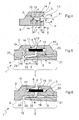
- FIG. 1 has a wall structure 1 shown here only in a small section at least two wall segments 2, 3, which are each shown here only in a small frontal edge region.
- the wall structure 1 comprises a plurality of such wall segments 2, 3 and is used to limit a hot gas path 4 in a gas turbine, not shown, or in a combustion chamber, not shown, in particular a gas turbine.
- the wall structure 1 form a shroud of the gas turbine or the combustion chamber, in which the individual wall segments 2, 3 are arranged in a cylindrical shape and form shroud segments of the shroud.
- Fig. 1 shows a connection region 5, in which two wall segments 2, 3 are arranged adjacent to each other.
- This connection region 5 is characterized by a curly bracket.
- one end face 6 of one wall segment 2 and one end face 7 of the other wall segment 3 are arranged opposite one another.
- the two end faces 6, 7 are spaced apart from each other and can thereby form a gap 8 between them.
- This gap 8 leads from an inner side 9 of the wall segments 2, 3 facing the hot gas path 4 to an outer side 10 of the wall segments 2, 3 facing away from the hot gas path 4.
- Each of the end faces 6, 7 contains a receiving groove 11 which is open towards the gap 8, respectively a groove base 12, the groove base 12 opposite groove opening 13 and two mutually opposite groove walls 14 have.
- the grooves 11 of the two end faces 6, 7 are arranged opposite one another.
- a sealing element 15 is inserted into the receiving grooves 11, which bridges the gap 8 and for this purpose engages in both receiving grooves 11.
- the sealing element 15 is usually a band-shaped body made of metal and preferably has a rectangular Cross-section. The corners of this rectangular cross-section can be more or less rounded. In principle, however, other cross-sectional geometries for the sealing element 15 are conceivable. For example, the sealing element 15 may have a rhombus-shaped cross section.
- the sealing element 15 may for example have a thickness S which is in a range of 0.2 mm to 1.5 mm.
- the sealing element 15 engages in the receiving grooves 11 with a lateral play.
- a distance A between the groove walls 14 of the respective groove 11 is greater than the thickness S of the sealing element 15.
- a ratio of the distance A to the thickness S is greater than or equal to 1.1.
- the distance A between the groove walls 14 is to be measured at the bottom of the groove 12, ie immediately before the groove base 12 or immediately before a possibly present rounded transition of the groove walls 14 to the groove bottom 12.
- the distance A can be measured at any point between groove bottom 12 and groove opening 13, since there the groove walls 14 are arranged parallel to each other.
- the thickness S of the sealing element 15 can be measured at any point in the embodiment shown here, since the rectangular cross-section of the sealing element 15 has a constant thickness S. If a sealing element 15 is used which has a thickness S varying over the width of the sealing element 15, then the thickness S at the lateral end of the sealing element 15 facing the respective groove bottom 12 is to be measured.
- the adjacent wall segments 2, 3 may have mutually different relative positions, in each case a sufficient sealing effect can be ensured.
- a variation of the relative positions of adjacent wall segments 2, 3 can arise due to thermal expansion effects.
- manufacturing tolerances for different relative positions of adjacent wall segments 2, 3 may be responsible.
- the sealing effect of the thus provided gap seal is achieved by a force with which the sealing element 15 is pressed against the closer to the hot gas path 4 arranged groove walls 14.
- This force effect can be generated, for example, by the pressure of a cooling medium, by centrifugal forces, by spring forces or the like.
- the groove walls 14 are inclined relative to one another, specifically from the groove opening 13 to the groove base 12. This results in a conical groove cross-section for the respective receiving groove 11 which widens up to the groove opening 13. With the help of such a conical groove cross-section very strong relative position changes between adjacent wall segments 2, 3 can be tolerated by the sealing element 15.
- Fig. 2 indicates an exaggerated representation of an extreme relative position, in which still a sufficient sealing effect can be achieved.
- values are preferred for the ratio of distance A to thickness S, which are in a range of 1.2 to 1.9.
- conical groove cross-section is crucial that the distance A is measured directly at the bottom of the groove 12, as in Fig. 3 is indicated.
- the dimensioning of the groove geometry is expediently such that a ratio of an opening width B measured at the groove opening 13 to the distance A has values which lie in a range from 1.2 to 4.
- a ratio of a groove depth T to the thickness S of the seal member 15 may be selected to have values ranging from 10 to 35. Due to the dimensions of distance A, opening width B and groove depth T, a cone angle ⁇ , with which the groove walls 14 are inclined relative to one another, can be determined.
- Fig. 4 shows a special embodiment of a groove geometry according to the invention.
- the receiving groove 11 here has a conical cross-sectional portion 16 and an adjoining constant cross-sectional portion 17.
- the two cross-sectional portions 16, 17 merge directly into each other. While the conical cross-sectional portion 16 extends up to the groove opening 13 and widens, the constant cross-sectional portion 17 extends to the groove base 12 and is characterized in that the groove walls 14 extend parallel to one another in it.
- the ratio of the distance A of the groove walls 14 to the thickness S of the sealing element 15 has values which lie in a range from 1.2 to 1.9.
- a ratio of opening width B to distance A such that values resulting therefrom are in the range from 1.2 to 4.
- a ratio of the total groove depth T to thickness S may be in a range of 10 to 35.
- a ratio of a depth K of the conical cross-sectional portion 16 to the total groove depth T has values, which are in a range of 0.1 to 0.8.
- a cone angle ⁇ can be determined from the stated ratios or from the dimensions mentioned, distance A, groove depth T, opening width B and depth K of the conical cross-sectional section 16.
- the groove base 12 is rounded or rounded. This rounding off can be realized, for example, with a radius R, with values that have proven useful for a ratio of radius R to distance A which lie in a range from 0.1 to 0.5.
- the groove bottom 12 is not shown rounded, it is clear that a rounded groove bottom 12 may be appropriate for all embodiments, preferably also in the other embodiments, the above calculation rule for the radius R can be used.
- the one wall segment 3 shown on the right is provided on its inner side 9 with a projection 18 which projects from the end face 7 of this wall segment 3.
- Quasi complementary to the other shown on the left wall segment 2 is provided on its inner side 9 with a recess 19 which is recessed on the inner side 6 of this wall segment 2.
- Projection 18 and recess 19 are coordinated so that the projection 18 protrudes into the recess 19 in such a way that results in a specific geometry for the gap 8. Due to the interaction of projection 18 and recess 19, the sealing element 19 is protected from direct application of hot gases from the hot gas path 4.
- any of the previously described embodiments may be equipped with such a projection-recess combination 18-19.
- the embodiment of the FIGS. 5 and 6 is also equipped with at least one cooling channel 20, which transports a cooling medium from an inlet, not shown, to an outlet 21, which opens into the gap 8 here.
- the cooling channel 20 is guided by the one wall segment 3 up to its end face 7. In principle, it is also possible not to let the cooling channel 20 end in the gap 8, but on the inside 9 of the respective wall segment 3.
- the other wall segment 2 may be equipped with at least one such cooling channel 20.
- cooling channel 20 can also be realized in a corresponding manner in one of the other embodiments described above.
- this projection 18 is provided with a conical cross section, so that the projection 18 tapers to the gap 8.
- the adjacent wall segments 2, 3 perform relative movements to each other without causing a contact between the projection 18 and the projection 18 facing wall 22 of the recess 19.
- the gap 8 always remains sufficiently wide open to avoid harmful contact between the wall segments 2, 3 which are coupled to one another in the connection region 5, and to prevent a blocking of the cooling channel 20.
- a ratio of a length D of the projection 18 to a final thickness E of the projection 18 at the free end 23 values have been found to be advantageous ranging from 1.5 to 6.
- the length D of the projection 18 is the dimension with which the projection 18 protrudes from the remaining end face 7 of the respective wall segment 3.
- the free end 23 of the projection 18 is located at the gap. 8
- a ratio of a gap width C between the protrusion 18 and the recess 19 to said final thickness E of the protrusion 18 may be selected to have values ranging from 1.0 to 5.
- the gap width C is measured without consideration of a possibly existing flattening 24, which may possibly be provided at the transition between gap 8 and inside 9 of the respective wall segment 2.
- values may be appropriate which are in a range of 2 ° to 60 °. Values of 5 ° to 15 ° are preferred.
Landscapes
- Engineering & Computer Science (AREA)
- Mechanical Engineering (AREA)
- General Engineering & Computer Science (AREA)
- Chemical & Material Sciences (AREA)
- Combustion & Propulsion (AREA)
- Turbine Rotor Nozzle Sealing (AREA)
- Gasket Seals (AREA)
- Physical Or Chemical Processes And Apparatus (AREA)
Claims (16)
- Structure de paroi pour la limitation d'un trajet de gaz chaud (4) dans une turbine à gaz ou dans une chambre de combustion, plus particulièrement d'une turbine à gaz,- avec au moins deux segments de paroi (2, 3) qui sont disposés de manière adjacente entre eux dans une zone de liaison (5),- un côté frontal (6) d'un segment de paroi (2) étant disposé, dans la zone de liaison (5), en face d'un côté frontal (7) de l'autre segment de paroi (3),- les côtés frontaux (6, 7) étant distants entre eux et formant entre eux un interstice (8) qui conduit d'un côté interne (9), orienté vers le trajet de gaz chaud (4), des segments de paroi (2, 3), vers un côté externe (10), opposé au trajet de gaz chaud (4), des segments de paroi (2, 3),- les côtés frontaux (6, 7) comprenant chacun une rainure de logement (11) ouverte vers l'interstice (8),- un élément d'étanchéité (15) recouvrant l'interstice (8) étant inséré dans les rainures de logement (11) disposées en face les unes des autres,- un rapport entre une distance (A), mesurée au niveau d'un fond de rainure (12) de la rainure de logement (11) correspondante, entre deux parois de rainures (14) opposées à la rainure de logement (11) correspondante et une épaisseur (S) de l'élément d'étanchéité (15) étant supérieur ou égal à 1,1,caractérisée en ce que
un segment de paroi (3) comprend, au niveau du côté interne (9), une saillie (18) dépassant du côté frontal (7), qui dépasse dans un évidement (19) réalisé au niveau du côté frontal (6) de l'autre segment de paroi (2) sur son côté interne (9), la saillie (18) présentant une section transversale conique, qui rétrécit en direction de l'interstice (8) et
un rapport entre une largeur d'interstice (C) entre la saillie (18) et l'évidement (19) et une épaisseur finale (E) de la saillie (18) à son extrémité (23) se trouvant au niveau de l'interstice (8), étant de l'ordre de 1,0 à 5. - Structure de paroi selon la revendication 1, caractérisée en ce que- les parois de la rainure (14) sont parallèles entre elles,- le rapport entre la distance (A) et l'épaisseur (S) est de l'ordre de 2,5 à 3,5.
- Structure de paroi selon la revendication 1, caractérisée en ce que- chaque rainure de logement (11) présente une section transversale conique s'élargissant jusqu'à une ouverture de rainure (13) avec des parois de rainure (14) s'étendant de manière inclinée jusqu'au fond de la rainure (12),- le rapport entre la distance (A) et l'épaisseur (S) est de l'ordre de 1,2 à 1,9.
- Structure de paroi selon la revendication 3, caractérisée en ce qu'un rapport entre une largeur d'ouverture (B) mesurée au niveau de l'ouverture de rainure (13) et une distance (A) mesurée au niveau du fond de la rainure (12) est de l'ordre de 1,2 à 4.
- Structure de paroi selon la revendication 3 ou 4, caractérisée en ce qu'un rapport entre une profondeur de rainure (T) et une épaisseur (S) de l'élément d'étanchéité (15) est de l'ordre de 10 à 35.
- Structure de paroi selon la revendication 1, caractérisée en ce que chaque rainure de logement (11) comprend une portion de section transversale conique (16) s'élargissant jusqu'à une ouverture de rainure (13), avec des parois de rainure (14) inclinées entre elles et une portion de section transversale (16) constante s'étendant jusqu'au fond de la rainure (12), avec des parois de rainure (14) parallèles entre elles.
- Structure de paroi selon la revendication 6, caractérisée en ce que le rapport entre la distance (A) et l'épaisseur (S) est de l'ordre de 1,2 à 9.
- Structure de paroi selon la revendication 6 ou 7, caractérisée en ce qu'un rapport entre une largeur d'ouverture (B) mesurée au niveau de l'ouverture de rainure (13) et la distance (A) mesurée au niveau du fond de la rainure (12) est de l'ordre de 1,2 à 4.
- Structure de paroi selon l'une des revendications 6 à 8, caractérisée en ce qu'un rapport entre une profondeur de rainure (T) et l'épaisseur (S) de l'élément d'étanchéité (15) est de l'ordre de 10 à 35.
- Structure de paroi selon l'une des revendications 6 à 9, caractérisée en ce qu'un rapport entre une profondeur (K) de la portion de section transversale conique (16) et une profondeur de rainure (T) est de l'ordre de 0,1 à 0,8.
- Structure de paroi selon l'une des revendications 1 à 10, caractérisée en ce que le fond de la rainure (12) est arrondi.
- Structure de paroi selon la revendication 11, caractérisée en ce que- le fond de la rainure (12) est arrondi avec un rayon (R),- un rapport entre le rayon (R) et la distance (A) est de l'ordre de 0,1 à 0,5.
- Structure de paroi selon l'une des revendications 1 à 12, caractérisée en ce que l'élément d'étanchéité (15) présente une section transversale rectangulaire avec ou sans angles arrondis.
- Structure de paroi selon l'une des revendications 1 à 13, qui comprend au moins un canal de refroidissement (20), qui débouche au niveau d'une sortie (21) dans l'interstice (8).
- Structure de paroi selon l'une des revendications 1 à 14, caractérisée en ce qu'un rapport entre une longueur (D) de la saillie (18), avec laquelle celle-ci dépasse du côté frontal (7), et une épaisseur finale (E) de la saillie (18) à son extrémité (23) se trouvant au niveau de l'interstice (8) est de l'ordre de 1,5 à 6.
- Structure de paroi selon l'une des revendications 1 à 15, caractérisée en ce qu'un angle de cône (α) de la saillie (18) est de l'ordre de 2° à 60°.
Applications Claiming Priority (1)
| Application Number | Priority Date | Filing Date | Title |
|---|---|---|---|
| DE102004037356.6A DE102004037356B4 (de) | 2004-07-30 | 2004-07-30 | Wandstruktur zur Begrenzung eines Heißgaspfads |
Publications (4)
| Publication Number | Publication Date |
|---|---|
| EP1621736A2 EP1621736A2 (fr) | 2006-02-01 |
| EP1621736A3 EP1621736A3 (fr) | 2012-02-22 |
| EP1621736B1 EP1621736B1 (fr) | 2013-04-17 |
| EP1621736B2 true EP1621736B2 (fr) | 2017-08-16 |
Family
ID=34981354
Family Applications (1)
| Application Number | Title | Priority Date | Filing Date |
|---|---|---|---|
| EP05106363.4A Not-in-force EP1621736B2 (fr) | 2004-07-30 | 2005-07-12 | Structure de paroi de conduits de gaz chauds de turbine à gaz |
Country Status (6)
| Country | Link |
|---|---|
| US (2) | US20060137351A1 (fr) |
| EP (1) | EP1621736B2 (fr) |
| KR (1) | KR101259179B1 (fr) |
| DE (1) | DE102004037356B4 (fr) |
| ES (1) | ES2421907T5 (fr) |
| MX (1) | MXPA05007887A (fr) |
Families Citing this family (17)
| Publication number | Priority date | Publication date | Assignee | Title |
|---|---|---|---|---|
| US7377742B2 (en) * | 2005-10-14 | 2008-05-27 | General Electric Company | Turbine shroud assembly and method for assembling a gas turbine engine |
| CH698921B1 (de) * | 2006-11-10 | 2009-12-15 | Alstom Technology Ltd | Strömungsmaschine. |
| ATE537333T1 (de) * | 2009-01-28 | 2011-12-15 | Alstom Technology Ltd | Streifendichtung und verfahren zum entwurf einer streifendichtung |
| US8287234B1 (en) * | 2009-08-20 | 2012-10-16 | Florida Turbine Technologies, Inc. | Turbine inter-segment mate-face cooling design |
| US8215115B2 (en) * | 2009-09-28 | 2012-07-10 | Hamilton Sundstrand Corporation | Combustor interface sealing arrangement |
| US8371800B2 (en) * | 2010-03-03 | 2013-02-12 | General Electric Company | Cooling gas turbine components with seal slot channels |
| FR2974839B1 (fr) * | 2011-05-04 | 2015-08-14 | Snecma | Anneau sectorise de turbine a orifices de ventilation, et turbomachine equipee d'un tel anneau |
| US9534783B2 (en) * | 2011-07-21 | 2017-01-03 | United Technologies Corporation | Insert adjacent to a heat shield element for a gas turbine engine combustor |
| US8845285B2 (en) * | 2012-01-10 | 2014-09-30 | General Electric Company | Gas turbine stator assembly |
| US8905708B2 (en) * | 2012-01-10 | 2014-12-09 | General Electric Company | Turbine assembly and method for controlling a temperature of an assembly |
| EP2961930B1 (fr) | 2013-02-26 | 2020-05-27 | United Technologies Corporation | Traitement des bords pour joint d'étanchéité à l'air externe d'aube |
| US20160194979A1 (en) * | 2013-09-06 | 2016-07-07 | United Technologies Corporation | Canted boas intersegment geometry |
| US10934871B2 (en) | 2015-02-20 | 2021-03-02 | Rolls-Royce North American Technologies Inc. | Segmented turbine shroud with sealing features |
| US10808576B2 (en) | 2017-02-06 | 2020-10-20 | General Electric Company | Methods of replacing seals in exhaust frames of turbine systems and related components |
| GB2559804A (en) * | 2017-02-21 | 2018-08-22 | Siemens Ag | Heatshield for a gas turbine |
| US10815807B2 (en) * | 2018-05-31 | 2020-10-27 | General Electric Company | Shroud and seal for gas turbine engine |
| US11852018B1 (en) * | 2022-08-10 | 2023-12-26 | General Electric Company | Turbine nozzle with planar surface adjacent side slash face |
Citations (6)
| Publication number | Priority date | Publication date | Assignee | Title |
|---|---|---|---|---|
| US3752598A (en) † | 1971-11-17 | 1973-08-14 | United Aircraft Corp | Segmented duct seal |
| US5374161A (en) † | 1993-12-13 | 1994-12-20 | United Technologies Corporation | Blade outer air seal cooling enhanced with inter-segment film slot |
| GB2356022A (en) † | 1999-11-02 | 2001-05-09 | Rolls Royce Plc | Cooling ends of a gas turbine engine liner |
| EP1286021A1 (fr) † | 2001-08-21 | 2003-02-26 | ALSTOM (Switzerland) Ltd | Procédé de fabrication d' un évidement ayant la forme d' une rainure et évidement ayant la forme d' une rainure correspondant |
| US20040067131A1 (en) † | 2002-10-08 | 2004-04-08 | Joslin Frederick R. | Leak resistant vane cluster |
| EP1519010A1 (fr) † | 2003-09-25 | 2005-03-30 | Siemens Westinghouse Power Corporation | Joint externe d'étanchéité à l'air |
Family Cites Families (12)
| Publication number | Priority date | Publication date | Assignee | Title |
|---|---|---|---|---|
| GB2076071B (en) * | 1980-05-16 | 1983-11-02 | United Technologies Corp | Flow directing assembly for a gas turbine engine |
| IT1164225B (it) * | 1983-05-13 | 1987-04-08 | Anic Spa | Analoghi retro-invertiti del pentapeptide potenziante la bradichina bpp5a e metodi per la loro preparazione |
| US4650394A (en) * | 1984-11-13 | 1987-03-17 | United Technologies Corporation | Coolable seal assembly for a gas turbine engine |
| US5154577A (en) * | 1991-01-17 | 1992-10-13 | General Electric Company | Flexible three-piece seal assembly |
| US5375973A (en) * | 1992-12-23 | 1994-12-27 | United Technologies Corporation | Turbine blade outer air seal with optimized cooling |
| US5476363A (en) * | 1993-10-15 | 1995-12-19 | Charles E. Sohl | Method and apparatus for reducing stress on the tips of turbine or compressor blades |
| DE69802848T2 (de) * | 1997-01-30 | 2002-08-08 | Snecma | Dichtung bestehend aus in einem Schlitz gestapelten Gleitstreifen |
| JP3999395B2 (ja) * | 1999-03-03 | 2007-10-31 | 三菱重工業株式会社 | ガスタービン分割環 |
| US6702549B2 (en) * | 2000-03-02 | 2004-03-09 | Siemens Aktiengesellschaft | Turbine installation |
| US6722846B2 (en) * | 2002-07-30 | 2004-04-20 | General Electric Company | Endface gap sealing of steam turbine bucket tip static seal segments and retrofitting thereof |
| US7033138B2 (en) * | 2002-09-06 | 2006-04-25 | Mitsubishi Heavy Industries, Ltd. | Ring segment of gas turbine |
| ATE366864T1 (de) * | 2003-02-19 | 2007-08-15 | Alstom Technology Ltd | Dichtungsanordnung, insbesondere für die schaufelsegmente von gasturbinen |
-
2004
- 2004-07-30 DE DE102004037356.6A patent/DE102004037356B4/de not_active Expired - Fee Related
-
2005
- 2005-07-12 EP EP05106363.4A patent/EP1621736B2/fr not_active Not-in-force
- 2005-07-12 ES ES05106363.4T patent/ES2421907T5/es active Active
- 2005-07-25 US US11/188,404 patent/US20060137351A1/en not_active Abandoned
- 2005-07-25 MX MXPA05007887A patent/MXPA05007887A/es active IP Right Grant
- 2005-07-30 KR KR1020050070042A patent/KR101259179B1/ko not_active IP Right Cessation
-
2009
- 2009-02-23 US US12/390,901 patent/US9353638B2/en not_active Expired - Fee Related
Patent Citations (7)
| Publication number | Priority date | Publication date | Assignee | Title |
|---|---|---|---|---|
| US3752598A (en) † | 1971-11-17 | 1973-08-14 | United Aircraft Corp | Segmented duct seal |
| US5374161A (en) † | 1993-12-13 | 1994-12-20 | United Technologies Corporation | Blade outer air seal cooling enhanced with inter-segment film slot |
| GB2356022A (en) † | 1999-11-02 | 2001-05-09 | Rolls Royce Plc | Cooling ends of a gas turbine engine liner |
| EP1286021A1 (fr) † | 2001-08-21 | 2003-02-26 | ALSTOM (Switzerland) Ltd | Procédé de fabrication d' un évidement ayant la forme d' une rainure et évidement ayant la forme d' une rainure correspondant |
| US20040067131A1 (en) † | 2002-10-08 | 2004-04-08 | Joslin Frederick R. | Leak resistant vane cluster |
| EP1519010A1 (fr) † | 2003-09-25 | 2005-03-30 | Siemens Westinghouse Power Corporation | Joint externe d'étanchéité à l'air |
| EP1519010B1 (fr) † | 2003-09-25 | 2006-06-21 | Siemens Power Generation, Inc. | Joint externe d'étanchéité à l'air |
Also Published As
| Publication number | Publication date |
|---|---|
| US9353638B2 (en) | 2016-05-31 |
| DE102004037356B4 (de) | 2017-11-23 |
| EP1621736A3 (fr) | 2012-02-22 |
| MXPA05007887A (es) | 2006-03-02 |
| DE102004037356A1 (de) | 2006-03-23 |
| EP1621736B1 (fr) | 2013-04-17 |
| KR101259179B1 (ko) | 2013-04-29 |
| EP1621736A2 (fr) | 2006-02-01 |
| ES2421907T5 (es) | 2018-01-09 |
| US20060137351A1 (en) | 2006-06-29 |
| KR20060048985A (ko) | 2006-05-18 |
| US20090155054A1 (en) | 2009-06-18 |
| ES2421907T3 (es) | 2013-09-06 |
Similar Documents
| Publication | Publication Date | Title |
|---|---|---|
| EP1621736B2 (fr) | Structure de paroi de conduits de gaz chauds de turbine à gaz | |
| EP1992414B1 (fr) | Buse de pulvérisation | |
| DE3828692C2 (fr) | ||
| EP1176343A2 (fr) | Joint d'étanchéité entre éléments statiques d'une turbine | |
| WO1998036817A1 (fr) | Disque, en particulier disque frontal, d'une cartouche filtrante | |
| EP2017508B1 (fr) | Dispositif de joint et procédé d'étanchéification d'un espace intermédiaire ainsi que groupe composants de réception d'un joint | |
| EP3071797B1 (fr) | Système de joint permettant d'étanchéifier une fente entre deux composants reposant à plat l'un contre l'autre à température ambiante | |
| DE69812837T2 (de) | Doppelkreuzdichtung für Gasturbinenleitschaufeln | |
| DE102016116614A1 (de) | Lufteinlass-Kontruktion für einen Motor | |
| DE2459425A1 (de) | Thermische turbomaschine, insbesondere dampfturbine | |
| WO2005095763A1 (fr) | Joint pour rendre etanche une fente separant deux composants voisins | |
| DE102014108997A1 (de) | Hochtemperaturventil für eine Verbrennungskraftmaschine | |
| DE2654688C2 (fr) | ||
| DE19934383C2 (de) | Dämpfungseinrichtung und Ventileinsatz für eine solche Dämpfungseinrichtung | |
| DE4037863C2 (fr) | ||
| DE2432181B2 (de) | Dichtungsanordnung | |
| DE10062204A1 (de) | Wellenabdichtung | |
| EP2841823A1 (fr) | Joint à cadre support à encombrement réduit | |
| DE2211808A1 (de) | Spitzendichtungsvorrichtung für eine Drehkolbenmaschine | |
| WO2008064773A1 (fr) | Dispositif d'étanchéité | |
| DE1775396C3 (de) | Dichtungsring | |
| EP2131079B1 (fr) | Système d'étanchéité d'arbres radiaux | |
| DE964192C (de) | Schubduese mit veraenderlichem Querschnitt fuer Strahltriebwerke | |
| EP2813712A1 (fr) | Unité de piston d'un cylindre plongeur | |
| WO2015074787A1 (fr) | Bague d'étanchéité d'une turbine à vapeur ménagée entre deux moitiés de carter et positionnée dans des gorges annulaires |
Legal Events
| Date | Code | Title | Description |
|---|---|---|---|
| PUAI | Public reference made under article 153(3) epc to a published international application that has entered the european phase |
Free format text: ORIGINAL CODE: 0009012 |
|
| AK | Designated contracting states |
Kind code of ref document: A2 Designated state(s): AT BE BG CH CY CZ DE DK EE ES FI FR GB GR HU IE IS IT LI LT LU LV MC NL PL PT RO SE SI SK TR |
|
| AX | Request for extension of the european patent |
Extension state: AL BA HR MK YU |
|
| PUAL | Search report despatched |
Free format text: ORIGINAL CODE: 0009013 |
|
| AK | Designated contracting states |
Kind code of ref document: A3 Designated state(s): AT BE BG CH CY CZ DE DK EE ES FI FR GB GR HU IE IS IT LI LT LU LV MC NL PL PT RO SE SI SK TR |
|
| AX | Request for extension of the european patent |
Extension state: AL BA HR MK YU |
|
| RIC1 | Information provided on ipc code assigned before grant |
Ipc: F01D 11/00 20060101AFI20120119BHEP |
|
| 17P | Request for examination filed |
Effective date: 20120809 |
|
| AKX | Designation fees paid |
Designated state(s): AT BE BG CH CY CZ DE DK EE ES FI FR GB GR HU IE IS IT LI LT LU LV MC NL PL PT RO SE SI SK TR |
|
| GRAP | Despatch of communication of intention to grant a patent |
Free format text: ORIGINAL CODE: EPIDOSNIGR1 |
|
| GRAS | Grant fee paid |
Free format text: ORIGINAL CODE: EPIDOSNIGR3 |
|
| GRAA | (expected) grant |
Free format text: ORIGINAL CODE: 0009210 |
|
| AK | Designated contracting states |
Kind code of ref document: B1 Designated state(s): AT BE BG CH CY CZ DE DK EE ES FI FR GB GR HU IE IS IT LI LT LU LV MC NL PL PT RO SE SI SK TR |
|
| REG | Reference to a national code |
Ref country code: GB Ref legal event code: FG4D Free format text: NOT ENGLISH |
|
| REG | Reference to a national code |
Ref country code: DE Ref legal event code: R081 Ref document number: 502005013632 Country of ref document: DE Owner name: GENERAL ELECTRIC TECHNOLOGY GMBH, CH Free format text: FORMER OWNER: ALSTOM TECHNOLOGY LTD., BADEN, CH Ref country code: DE Ref legal event code: R081 Ref document number: 502005013632 Country of ref document: DE Owner name: ANSALDO ENERGIA IP UK LIMITED, GB Free format text: FORMER OWNER: ALSTOM TECHNOLOGY LTD., BADEN, CH |
|
| REG | Reference to a national code |
Ref country code: CH Ref legal event code: EP |
|
| REG | Reference to a national code |
Ref country code: IE Ref legal event code: FG4D Free format text: LANGUAGE OF EP DOCUMENT: GERMAN |
|
| REG | Reference to a national code |
Ref country code: AT Ref legal event code: REF Ref document number: 607431 Country of ref document: AT Kind code of ref document: T Effective date: 20130515 |
|
| REG | Reference to a national code |
Ref country code: DE Ref legal event code: R096 Ref document number: 502005013632 Country of ref document: DE Effective date: 20130613 |
|
| REG | Reference to a national code |
Ref country code: LT Ref legal event code: MG4D |
|
| REG | Reference to a national code |
Ref country code: NL Ref legal event code: VDEP Effective date: 20130417 |
|
| PG25 | Lapsed in a contracting state [announced via postgrant information from national office to epo] |
Ref country code: IS Free format text: LAPSE BECAUSE OF FAILURE TO SUBMIT A TRANSLATION OF THE DESCRIPTION OR TO PAY THE FEE WITHIN THE PRESCRIBED TIME-LIMIT Effective date: 20130817 Ref country code: SE Free format text: LAPSE BECAUSE OF FAILURE TO SUBMIT A TRANSLATION OF THE DESCRIPTION OR TO PAY THE FEE WITHIN THE PRESCRIBED TIME-LIMIT Effective date: 20130417 Ref country code: LT Free format text: LAPSE BECAUSE OF FAILURE TO SUBMIT A TRANSLATION OF THE DESCRIPTION OR TO PAY THE FEE WITHIN THE PRESCRIBED TIME-LIMIT Effective date: 20130417 Ref country code: PT Free format text: LAPSE BECAUSE OF FAILURE TO SUBMIT A TRANSLATION OF THE DESCRIPTION OR TO PAY THE FEE WITHIN THE PRESCRIBED TIME-LIMIT Effective date: 20130819 Ref country code: SI Free format text: LAPSE BECAUSE OF FAILURE TO SUBMIT A TRANSLATION OF THE DESCRIPTION OR TO PAY THE FEE WITHIN THE PRESCRIBED TIME-LIMIT Effective date: 20130417 Ref country code: GR Free format text: LAPSE BECAUSE OF FAILURE TO SUBMIT A TRANSLATION OF THE DESCRIPTION OR TO PAY THE FEE WITHIN THE PRESCRIBED TIME-LIMIT Effective date: 20130718 Ref country code: FI Free format text: LAPSE BECAUSE OF FAILURE TO SUBMIT A TRANSLATION OF THE DESCRIPTION OR TO PAY THE FEE WITHIN THE PRESCRIBED TIME-LIMIT Effective date: 20130417 |
|
| PG25 | Lapsed in a contracting state [announced via postgrant information from national office to epo] |
Ref country code: CY Free format text: LAPSE BECAUSE OF FAILURE TO SUBMIT A TRANSLATION OF THE DESCRIPTION OR TO PAY THE FEE WITHIN THE PRESCRIBED TIME-LIMIT Effective date: 20130417 Ref country code: LV Free format text: LAPSE BECAUSE OF FAILURE TO SUBMIT A TRANSLATION OF THE DESCRIPTION OR TO PAY THE FEE WITHIN THE PRESCRIBED TIME-LIMIT Effective date: 20130417 Ref country code: BG Free format text: LAPSE BECAUSE OF FAILURE TO SUBMIT A TRANSLATION OF THE DESCRIPTION OR TO PAY THE FEE WITHIN THE PRESCRIBED TIME-LIMIT Effective date: 20130717 Ref country code: PL Free format text: LAPSE BECAUSE OF FAILURE TO SUBMIT A TRANSLATION OF THE DESCRIPTION OR TO PAY THE FEE WITHIN THE PRESCRIBED TIME-LIMIT Effective date: 20130417 |
|
| PLBI | Opposition filed |
Free format text: ORIGINAL CODE: 0009260 |
|
| BERE | Be: lapsed |
Owner name: ALSTOM TECHNOLOGY LTD Effective date: 20130731 |
|
| PG25 | Lapsed in a contracting state [announced via postgrant information from national office to epo] |
Ref country code: DK Free format text: LAPSE BECAUSE OF FAILURE TO SUBMIT A TRANSLATION OF THE DESCRIPTION OR TO PAY THE FEE WITHIN THE PRESCRIBED TIME-LIMIT Effective date: 20130417 Ref country code: CZ Free format text: LAPSE BECAUSE OF FAILURE TO SUBMIT A TRANSLATION OF THE DESCRIPTION OR TO PAY THE FEE WITHIN THE PRESCRIBED TIME-LIMIT Effective date: 20130417 Ref country code: EE Free format text: LAPSE BECAUSE OF FAILURE TO SUBMIT A TRANSLATION OF THE DESCRIPTION OR TO PAY THE FEE WITHIN THE PRESCRIBED TIME-LIMIT Effective date: 20130417 Ref country code: SK Free format text: LAPSE BECAUSE OF FAILURE TO SUBMIT A TRANSLATION OF THE DESCRIPTION OR TO PAY THE FEE WITHIN THE PRESCRIBED TIME-LIMIT Effective date: 20130417 |
|
| PLAX | Notice of opposition and request to file observation + time limit sent |
Free format text: ORIGINAL CODE: EPIDOSNOBS2 |
|
| 26 | Opposition filed |
Opponent name: SIEMENS AKTIENGESELLSCHAFT Effective date: 20140117 |
|
| PG25 | Lapsed in a contracting state [announced via postgrant information from national office to epo] |
Ref country code: MC Free format text: LAPSE BECAUSE OF FAILURE TO SUBMIT A TRANSLATION OF THE DESCRIPTION OR TO PAY THE FEE WITHIN THE PRESCRIBED TIME-LIMIT Effective date: 20130417 Ref country code: NL Free format text: LAPSE BECAUSE OF FAILURE TO SUBMIT A TRANSLATION OF THE DESCRIPTION OR TO PAY THE FEE WITHIN THE PRESCRIBED TIME-LIMIT Effective date: 20130417 Ref country code: RO Free format text: LAPSE BECAUSE OF FAILURE TO SUBMIT A TRANSLATION OF THE DESCRIPTION OR TO PAY THE FEE WITHIN THE PRESCRIBED TIME-LIMIT Effective date: 20130417 Ref country code: IT Free format text: LAPSE BECAUSE OF FAILURE TO SUBMIT A TRANSLATION OF THE DESCRIPTION OR TO PAY THE FEE WITHIN THE PRESCRIBED TIME-LIMIT Effective date: 20130417 |
|
| REG | Reference to a national code |
Ref country code: CH Ref legal event code: PL |
|
| REG | Reference to a national code |
Ref country code: DE Ref legal event code: R026 Ref document number: 502005013632 Country of ref document: DE Effective date: 20140117 |
|
| REG | Reference to a national code |
Ref country code: IE Ref legal event code: MM4A |
|
| REG | Reference to a national code |
Ref country code: FR Ref legal event code: ST Effective date: 20140331 |
|
| PG25 | Lapsed in a contracting state [announced via postgrant information from national office to epo] |
Ref country code: CH Free format text: LAPSE BECAUSE OF NON-PAYMENT OF DUE FEES Effective date: 20130731 Ref country code: BE Free format text: LAPSE BECAUSE OF NON-PAYMENT OF DUE FEES Effective date: 20130731 Ref country code: LI Free format text: LAPSE BECAUSE OF NON-PAYMENT OF DUE FEES Effective date: 20130731 |
|
| PG25 | Lapsed in a contracting state [announced via postgrant information from national office to epo] |
Ref country code: FR Free format text: LAPSE BECAUSE OF NON-PAYMENT OF DUE FEES Effective date: 20130731 |
|
| PLAF | Information modified related to communication of a notice of opposition and request to file observations + time limit |
Free format text: ORIGINAL CODE: EPIDOSCOBS2 |
|
| PG25 | Lapsed in a contracting state [announced via postgrant information from national office to epo] |
Ref country code: IE Free format text: LAPSE BECAUSE OF NON-PAYMENT OF DUE FEES Effective date: 20130712 |
|
| PLBB | Reply of patent proprietor to notice(s) of opposition received |
Free format text: ORIGINAL CODE: EPIDOSNOBS3 |
|
| REG | Reference to a national code |
Ref country code: AT Ref legal event code: MM01 Ref document number: 607431 Country of ref document: AT Kind code of ref document: T Effective date: 20130712 |
|
| PG25 | Lapsed in a contracting state [announced via postgrant information from national office to epo] |
Ref country code: AT Free format text: LAPSE BECAUSE OF NON-PAYMENT OF DUE FEES Effective date: 20130712 |
|
| PLAB | Opposition data, opponent's data or that of the opponent's representative modified |
Free format text: ORIGINAL CODE: 0009299OPPO |
|
| R26 | Opposition filed (corrected) |
Opponent name: SIEMENS AKTIENGESELLSCHAFT Effective date: 20140117 |
|
| PG25 | Lapsed in a contracting state [announced via postgrant information from national office to epo] |
Ref country code: TR Free format text: LAPSE BECAUSE OF FAILURE TO SUBMIT A TRANSLATION OF THE DESCRIPTION OR TO PAY THE FEE WITHIN THE PRESCRIBED TIME-LIMIT Effective date: 20130417 |
|
| PG25 | Lapsed in a contracting state [announced via postgrant information from national office to epo] |
Ref country code: HU Free format text: LAPSE BECAUSE OF FAILURE TO SUBMIT A TRANSLATION OF THE DESCRIPTION OR TO PAY THE FEE WITHIN THE PRESCRIBED TIME-LIMIT; INVALID AB INITIO Effective date: 20050712 Ref country code: LU Free format text: LAPSE BECAUSE OF NON-PAYMENT OF DUE FEES Effective date: 20130712 |
|
| REG | Reference to a national code |
Ref country code: DE Ref legal event code: R081 Ref document number: 502005013632 Country of ref document: DE Owner name: GENERAL ELECTRIC TECHNOLOGY GMBH, CH Free format text: FORMER OWNER: ALSTOM TECHNOLOGY LTD., BADEN, CH Ref country code: DE Ref legal event code: R081 Ref document number: 502005013632 Country of ref document: DE Owner name: ANSALDO ENERGIA IP UK LIMITED, GB Free format text: FORMER OWNER: ALSTOM TECHNOLOGY LTD., BADEN, CH |
|
| RAP2 | Party data changed (patent owner data changed or rights of a patent transferred) |
Owner name: GENERAL ELECTRIC TECHNOLOGY GMBH |
|
| RIC2 | Information provided on ipc code assigned after grant |
Ipc: F02C 7/12 20060101ALI20161005BHEP Ipc: F01D 11/02 20060101AFI20161005BHEP Ipc: F01D 11/00 20060101ALI20161005BHEP Ipc: F02C 7/28 20060101ALI20161005BHEP Ipc: F01D 25/12 20060101ALI20161005BHEP |
|
| RAP2 | Party data changed (patent owner data changed or rights of a patent transferred) |
Owner name: ANSALDO ENERGIA IP UK LIMITED |
|
| PUAH | Patent maintained in amended form |
Free format text: ORIGINAL CODE: 0009272 |
|
| STAA | Information on the status of an ep patent application or granted ep patent |
Free format text: STATUS: PATENT MAINTAINED AS AMENDED |
|
| 27A | Patent maintained in amended form |
Effective date: 20170816 |
|
| AK | Designated contracting states |
Kind code of ref document: B2 Designated state(s): AT BE BG CH CY CZ DE DK EE ES FI FR GB GR HU IE IS IT LI LT LU LV MC NL PL PT RO SE SI SK TR |
|
| REG | Reference to a national code |
Ref country code: DE Ref legal event code: R102 Ref document number: 502005013632 Country of ref document: DE |
|
| REG | Reference to a national code |
Ref country code: DE Ref legal event code: R081 Ref document number: 502005013632 Country of ref document: DE Owner name: ANSALDO ENERGIA IP UK LIMITED, GB Free format text: FORMER OWNER: GENERAL ELECTRIC TECHNOLOGY GMBH, BADEN, CH |
|
| REG | Reference to a national code |
Ref country code: GB Ref legal event code: 732E Free format text: REGISTERED BETWEEN 20170824 AND 20170830 |
|
| PGFP | Annual fee paid to national office [announced via postgrant information from national office to epo] |
Ref country code: ES Payment date: 20170825 Year of fee payment: 13 Ref country code: GB Payment date: 20170719 Year of fee payment: 13 Ref country code: DE Payment date: 20170724 Year of fee payment: 13 |
|
| REG | Reference to a national code |
Ref country code: ES Ref legal event code: DC2A Ref document number: 2421907 Country of ref document: ES Kind code of ref document: T5 Effective date: 20180109 |
|
| REG | Reference to a national code |
Ref country code: DE Ref legal event code: R119 Ref document number: 502005013632 Country of ref document: DE |
|
| GBPC | Gb: european patent ceased through non-payment of renewal fee |
Effective date: 20180712 |
|
| PG25 | Lapsed in a contracting state [announced via postgrant information from national office to epo] |
Ref country code: DE Free format text: LAPSE BECAUSE OF NON-PAYMENT OF DUE FEES Effective date: 20190201 Ref country code: GB Free format text: LAPSE BECAUSE OF NON-PAYMENT OF DUE FEES Effective date: 20180712 |
|
| REG | Reference to a national code |
Ref country code: ES Ref legal event code: FD2A Effective date: 20190917 |
|
| PG25 | Lapsed in a contracting state [announced via postgrant information from national office to epo] |
Ref country code: ES Free format text: LAPSE BECAUSE OF NON-PAYMENT OF DUE FEES Effective date: 20180713 |