EP1621689B1 - Wandeinbau-Spülkasten - Google Patents
Wandeinbau-Spülkasten Download PDFInfo
- Publication number
- EP1621689B1 EP1621689B1 EP05015722A EP05015722A EP1621689B1 EP 1621689 B1 EP1621689 B1 EP 1621689B1 EP 05015722 A EP05015722 A EP 05015722A EP 05015722 A EP05015722 A EP 05015722A EP 1621689 B1 EP1621689 B1 EP 1621689B1
- Authority
- EP
- European Patent Office
- Prior art keywords
- locking
- piece
- filling valve
- box body
- cross
- Prior art date
- Legal status (The legal status is an assumption and is not a legal conclusion. Google has not performed a legal analysis and makes no representation as to the accuracy of the status listed.)
- Expired - Lifetime
Links
Images

Classifications
-
- E—FIXED CONSTRUCTIONS
- E03—WATER SUPPLY; SEWERAGE
- E03D—WATER-CLOSETS OR URINALS WITH FLUSHING DEVICES; FLUSHING VALVES THEREFOR
- E03D1/00—Water flushing devices with cisterns ; Setting up a range of flushing devices or water-closets; Combinations of several flushing devices
- E03D1/01—Shape or selection of material for flushing cisterns
- E03D1/012—Details of shape of cisterns, e.g. for connecting to wall, for supporting or connecting flushing-device actuators
- E03D1/0125—Details of shape of cisterns, e.g. for connecting to wall, for supporting or connecting flushing-device actuators of built-in cisterns
Definitions
- the invention relates to a wall-mounted cistern with a box body, in which an inlet valve, a drain valve and a traverse are arranged, wherein the inlet valve is received by a arranged on a wall of the box body plug-in holder.
- the invention is therefore based on the object to provide in the specified in the preamble of claim 1 wall-mounted cistern an improved support for the inlet valve.
- the locking of the attachment of the filling valve in the box body using a stabilization of the box body and the storage of an actuating lever for the drain valve serving traverse.
- the filling valve can be removed without further levers and hooks to be removed from the box body. It thus enables easy maintenance through the small inspection shaft without manipulations requiring explanation.
- the secured mounting of the filling valve in the box body thus takes place virtually with a self-explanatory locking.
- an adapter for the plug-fastening on the box body while at least one laterally projecting locking tab is arranged on the cross member, which in the locking on the Adapter or formed on the adapter tongue summarizes.
- the adapter with the tongue and the Traverse with one or more locking tabs are each made in one piece of plastic injection-molded inexpensively.
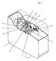
- the wall-mounted cistern shown in the drawing has a box body 1 made by blowing on plastic, which carries a side access opening 11 and an inspection opening 12 in the cover page.
- a holding plate 13 is attached to the box body 1.
- a prism-like vertical plug-in holder 10 is arranged at both end regions, at the lower region in each case a stop surface 100 is formed.
- the holding plate 13 holding means for a cross member 4, which serves to stabilize the box body 1 and also forms a bearing for a lever 41 for actuating a drain valve via an overflow pipe 5.
- a filling valve 2 is provided in the wall-mounted cistern.
- the filling valve 2 is attached to an adapter 3.
- the adapter 3 has two oppositely formed receptacles 31 for the plug-in holder 10.
- the two opposite receptacles 31 are required for the optional use of the filling valve 2 in the left half of the box body 1 or in the right half of the box body 1.
- an angle-shaped locking tab 40 is integrally formed approximately in the middle of the box body 1 on both sides.
- a tongue 30 is integrally formed on the adapter 3, such that in the inserted position of the filling valve 2, one of the two locking tabs 40 engages over the tongue 30 and thus the inserted position of the adapter 3 and thus also of the filling valve 2 in locked the box body 1.
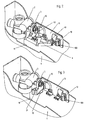
- the Traverse 4 raised on one side as it is in FIG. 2 the drawing is shown.
- the cross member 4 can be removed, whereby the adapter 3 is unlocked with the filling valve 2, as is made FIG. 3 the drawing can be seen.
- the filling valve 2 can be pulled out with the adapter 3 from the plug-in holder 10 on the holding plate 13 of the box body, as in FIG. 4 the drawing is shown.
- the new filling valve 2 can be introduced in the reverse order in the box body 1 and fixed in the mounting position on the plug-in holder 10.
- the filling valve 2 is automatically locked to the plug holder 10 by means of the tongue 30 and a locking tab 40 again.
Landscapes
- Health & Medical Sciences (AREA)
- Life Sciences & Earth Sciences (AREA)
- Engineering & Computer Science (AREA)
- Hydrology & Water Resources (AREA)
- Public Health (AREA)
- Water Supply & Treatment (AREA)
- Valve Housings (AREA)
- Residential Or Office Buildings (AREA)
- Sewage (AREA)
- Sanitary Device For Flush Toilet (AREA)
- Diaphragms For Electromechanical Transducers (AREA)
- Transition And Organic Metals Composition Catalysts For Addition Polymerization (AREA)
- Toilet Supplies (AREA)
- Mechanically-Actuated Valves (AREA)
Description
- Die Erfindung betrifft einen Wandeinbau-Spülkasten mit einem Kastenkörper, in dem ein Zulaufventil, ein Ablaufventil und eine Traverse angeordnet sind, wobei das Zulaufventil von einer an einer Wand des Kastenkörpers angeordneten Steckhalterung aufgenommen ist.
- Es sind bereits Wandeinbau-Spülkästen bekannt, bei denen das Füllventil an einer Steckhalterung an der Rückwand des Kastenkörpers angeordnet ist, siehe z.B
WO-A-9954561 - Der Erfindung liegt daher die Aufgabe zugrunde, bei dem im Oberbegriff des Anspruchs 1 angegebenen Wandeinbau-Spülkasten eine verbesserte Halterung für das Zulaufventil zu schaffen.
- Diese Aufgabe wird bei einem gattungsgemäßen Wandeinbau-Spülkasten dadurch gelöst, dass die Stecklage des Füllventils von der lösbar im Kastenkörper angeordneten Traverse verriegelt ist.
Weitere Ausgestaltungen der Erfindung sind in den Ansprüchen 2 bis 7 angegeben. - Mit den vorgeschlagenen erfindungsgemäßen Maßnahmen wird insbesondere erreicht, dass die Verriegelung der Befestigung des Füllventils im Kastenkörper mit Hilfe einer der Stabilisierung des Kastenkörpers und der Lagerung eines Betätigungshebels für das Ablaufventil dienenden Traverse erfolgt. Nach der Entnahme der Traverse aus dem Kastenkörper kann das Füllventil ohne weitere Hebel und Haken zu lösen aus dem Kastenkörper entnommen werden. Sie ermöglicht somit eine einfache Wartung durch den kleinen Revisionsschacht ohne erklärungsbedürftige Handhabungen. Die gesicherte Halterung des Füllventils im Kastenkörper erfolgt somit quasi mit einer selbsterklärenden Verriegelung.
- In weiterer Ausgestaltung der Erfindung kann zweckmäßig am Füllventil ein Adapter für die Steckbefestigung am Kastenkörper vorgesehen werden, während an der Traverse wenigstens eine seitlich vorstehende Riegellasche angeordnet ist, die bei der Verriegelung über den Adapter oder eine an dem Adapter angeformte Zunge fasst. Vorteilhaft kann der Adapter mit der Zunge sowie die Traverse mit einer oder mehreren Riegellaschen jeweils einstückig aus Kunststoff im Spritzgussverfahren preiswert hergestellt werden.
- Ein Ausführungsbeispiel der Erfindung ist in der Zeichnung dargestellt und wird im folgenden näher beschrieben. Es zeigt in der Zeichnung
- Figur 1
- einen Wandeinbau-Spülkasten in Perspektivansicht mit einem von einer Traverse im Kastenkörper verriegelt gehaltenen Füllventil;
- Figur 2
- einen Teil des in
Figur 1 gezeigten Kastenkörpers mit einseitig angehobener Traverse in vergrößerter Darstellung; - Figur 3
- den in
Figur 2 dargestellten Teil des Kastenkörpers mit entfernter Traverse; - Figur 4
- den in
Figur 3 dargestellten Teil des Kastenkörpers mit zur Entnahme angehobenem Füllventil. - Der in
Figur 1 der Zeichnung dargestellte Wandeinbau-Spülkasten weist einen im Blasverfahren aus Kunststoff hergestellten Kastenkörper 1 auf, der eine seitliche Revisionsöffnung 11 und eine Revisionsöffnung 12 in der Deckseite trägt. An der der Revisionsöffnung 11 gegenüberliegenden Rückseite ist eine Halteplatte 13 am Kastenkörper 1 befestigt. An der Halteplatte 13 ist an beiden Endbereichen jeweils eine prismenartige vertikale Steckhalterung 10 angeordnet, an deren unteren Bereich jeweils eine Anschlagfläche 100 ausgebildet ist. Außerdem weist die Halteplatte 13 Haltemittel für eine Traverse 4 auf, die zur Stabilisierung des Kastenkörpers 1 dient und außerdem ein Lager für einen Hebel 41 zur Betätigung eines Ablaufventils über ein Überlaufrohr 5 bildet.
Für den Wasserzufluss ist in dem Wandeinbau-Spülkasten ein Füllventil 2 vorgesehen. Das Füllventil 2 ist an einem Adapter 3 befestigt. Der Adapter 3 weist dabei zwei gegenüberliegend ausgebildete Aufnahmen 31 für die Steckhalterung 10 auf. Die beiden gegenüberliegenden Aufnahmen 31 werden für den wahlweisen Einsatz des Füllventils 2 in der linken Hälfte des Kastenkörpers 1 oder in der Rechten Hälfte des Kastenkörpers 1 benötigt.
An der Traverse 4 ist etwa in der Mitte des Kastenkörpers 1 an beiden Seiten jeweils eine winkelförmige Riegellasche 40 angeformt. Als Gegenstück zu den beiden Riegellaschen 40 ist an dem Adapter 3 eine Zunge 30 angeformt, derart, dass in der Stecklage des Füllventils 2 eine der beiden Riegellaschen 40 über die Zunge 30 greift und somit die Stecklage des Adapters 3 und damit auch des Füllventils 2 in dem Kastenkörper 1 verriegelt. - Bei der Wartung oder auch einem Austausch des Füllventils 2 kann somit über die Revisionsöffnung 11 die Traverse 4 einseitig angehoben werden, wie es in
Figur 2 der Zeichnung dargestellt ist. Sodann kann die Traverse 4 entnommen werden, wodurch der Adapter 3 mit dem Füllventil 2 entriegelt ist, wie es ausFigur 3 der Zeichnung zu entnehmen ist. Hiernach kann durch eine Vertikalverschiebung das Füllventil 2 mit dem Adapter 3 aus der Steckhalterung 10 an der Halteplatte 13 des Kastenkörpers herausgezogen werden, wie es inFigur 4 der Zeichnung dargestellt ist. Nach den Wartungsarbeiten oder bei einem Austausch des Füllventils 2 kann das neue Füllventil 2 in umgekehrter Reihenfolge in den Kastenkörper 1 eingebracht und in der Montageposition an der Steckhalterung 10 befestigt werden. Mit dem abschließenden Einbau der Traverse 4 wird das Füllventil 2 an der Steckhalterung 10 mit Hilfe der Zunge 30 und einer Riegellasche 40 automatisch wieder verriegelt.
Claims (7)
- Wandeinbau-Spülkasten mit einem Kastenkörper (1), in dem ein Füllventil (2), ein Ablaufventil und eine Traverse (4) angeordnet sind, wobei das Füllventil (2) von einer an einer Wand des Kastenkörpers (1) angeordneten Steckhalterung aufgenommen ist, dadurch gekennzeichnet, dass die Stecklage des Füllventils (2) von der lösbar im Kastenkörper (1) angeordneten Traverse (4) verriegelt ist.
- Wandeinbau-Spülkasten nach Anspruch 1, dadurch gekennzeichnet, dass das Füllventil (2) an einem Adapter (3) befestigt ist, der von der Steckhalterung (10) aufgenommen ist, wobei die lösbare Traverse (4) den Adapter (3) in der Stecklage verriegelt.
- Wandeinbau-Spülkasten nach Anspruch 1 oder 2, dadurch gekennzeichnet, dass zur Verriegelung an der Traverse (4) wenigstens eine Riegellasche (40) vorgesehen ist.
- Wandeinbau-Spülkasten nach Anspruch 3, dadurch gekennzeichnet, dass die Traverse (4) und die Riegellaschen (40) einstückig aus Kunststoff hergestellt sind.
- Wandeinbau-Spülkasten nach wenigstens einem der vorhergehenden Ansprüche, dadurch gekennzeichnet, dass an dem Zulaufventil oder dem Adapter (3) eine vorstehende Zunge (30) vorgesehen ist, über die in der Montageposition die Traverse zur Verriegelung fasst.
- Wandeinbau-Spülkasten nach Anspruch 5, dadurch gekennzeichnet, dass die Zunge (30) mit dem Adapter (3) einstückig aus Kunststoff hergestellt ist.
- Wandeinbau-Spülkasten nach Anspruch 5 oder 6, dadurch gekennzeichnet, dass die Traverse (4) mit einer Riegellasche (40) in der Montageposition zur Verriegelung über die Zunge (30) fasst.
Applications Claiming Priority (1)
| Application Number | Priority Date | Filing Date | Title |
|---|---|---|---|
| DE102004037050A DE102004037050A1 (de) | 2004-07-29 | 2004-07-29 | Wandeinbau-Spülkasten |
Publications (3)
| Publication Number | Publication Date |
|---|---|
| EP1621689A2 EP1621689A2 (de) | 2006-02-01 |
| EP1621689A3 EP1621689A3 (de) | 2006-08-09 |
| EP1621689B1 true EP1621689B1 (de) | 2008-08-27 |
Family
ID=35262170
Family Applications (1)
| Application Number | Title | Priority Date | Filing Date |
|---|---|---|---|
| EP05015722A Expired - Lifetime EP1621689B1 (de) | 2004-07-29 | 2005-07-20 | Wandeinbau-Spülkasten |
Country Status (3)
| Country | Link |
|---|---|
| EP (1) | EP1621689B1 (de) |
| AT (1) | ATE406484T1 (de) |
| DE (2) | DE102004037050A1 (de) |
Family Cites Families (1)
| Publication number | Priority date | Publication date | Assignee | Title |
|---|---|---|---|---|
| DE29900976U1 (de) * | 1998-04-20 | 1999-05-06 | Geberit Technik Ag, Jona | Spülkasten |
-
2004
- 2004-07-29 DE DE102004037050A patent/DE102004037050A1/de not_active Withdrawn
-
2005
- 2005-07-20 DE DE502005005172T patent/DE502005005172D1/de not_active Expired - Lifetime
- 2005-07-20 AT AT05015722T patent/ATE406484T1/de not_active IP Right Cessation
- 2005-07-20 EP EP05015722A patent/EP1621689B1/de not_active Expired - Lifetime
Also Published As
| Publication number | Publication date |
|---|---|
| EP1621689A3 (de) | 2006-08-09 |
| ATE406484T1 (de) | 2008-09-15 |
| DE502005005172D1 (de) | 2008-10-09 |
| EP1621689A2 (de) | 2006-02-01 |
| DE102004037050A1 (de) | 2006-03-23 |
Similar Documents
| Publication | Publication Date | Title |
|---|---|---|
| EP2045403B1 (de) | Ablaufgarnitur mit integriertem Überlauf | |
| EP3705650B1 (de) | Wc-aufsatz | |
| DE202014003479U1 (de) | Unterflur-Wasserversorgungseinrichtung für Zugwaggons | |
| EP2275610B1 (de) | Wasserkasten für ein Klosett und entsprechendes Klosett | |
| EP3502364B1 (de) | Rohrbelüfter und system zur rohrbelüftung | |
| EP0047482B1 (de) | Abwasserrohr mit Reinigungsöffnung und wegnehmbarer Rückstauklappe | |
| DE1902751A1 (de) | Wasserclosett | |
| EP3705647B1 (de) | Spülkasten mit füllventil | |
| EP1605109A1 (de) | Klosettschüssel für ein WC | |
| DE102015109241B4 (de) | Rückstauverschluss | |
| EP2186953A2 (de) | Raumsparsifon und System aus Raumsparsifon und Überlaufsicherung | |
| EP1621689A2 (de) | Wandeinbau-Spülkasten | |
| EP0185109B1 (de) | Geruchsverschluss | |
| DE102017111073B4 (de) | Vorrichtung zur Spülung und/oder thermischen Desinfektion von Rohrleitungen | |
| DE102023123249A1 (de) | Anordnungssystem zur Anordnung eines Spülbehälters eines Sanitärausstattungsgegenstandes | |
| DE102016108510A1 (de) | Ablaufventil für einen Spülkasten und Spülkasten mit Ablaufventil | |
| DE202015107000U1 (de) | Ablaufsystem | |
| EP3680406A1 (de) | Ablaufvorrichtung für den einbau in den boden eines raumes | |
| DE102018133514A1 (de) | WC-Anschlussvorrichtung zum wandseitigen Anschluss eines Dusch-WC und Verfahren zur Installation eines Dusch-WC unter Verwendung einer WC-Anschlussvorrichtung | |
| EP1932972B1 (de) | Spülkasten mit kombinierter Füllventil- und Ablaufventilsitzhalterung | |
| EP4520887B1 (de) | Bodeneinlauf mit geruchsverschluss | |
| DE29501299U1 (de) | Montagerahmen für Sanitärkörper | |
| DE102008003274B3 (de) | Kupplungsvorrichtung | |
| DE102023123248A1 (de) | Anordnungssystem zur Anordnung eines Spülbehälters eines Sanitärausstattungsgegenstandes | |
| EP2105542A1 (de) | Ventilanordnung für eine Spülvorrichtung |
Legal Events
| Date | Code | Title | Description |
|---|---|---|---|
| PUAI | Public reference made under article 153(3) epc to a published international application that has entered the european phase |
Free format text: ORIGINAL CODE: 0009012 |
|
| AK | Designated contracting states |
Kind code of ref document: A2 Designated state(s): AT BE BG CH CY CZ DE DK EE ES FI FR GB GR HU IE IS IT LI LT LU LV MC NL PL PT RO SE SI SK TR |
|
| AX | Request for extension of the european patent |
Extension state: AL BA HR MK YU |
|
| PUAL | Search report despatched |
Free format text: ORIGINAL CODE: 0009013 |
|
| AK | Designated contracting states |
Kind code of ref document: A3 Designated state(s): AT BE BG CH CY CZ DE DK EE ES FI FR GB GR HU IE IS IT LI LT LU LV MC NL PL PT RO SE SI SK TR |
|
| AX | Request for extension of the european patent |
Extension state: AL BA HR MK YU |
|
| RIC1 | Information provided on ipc code assigned before grant |
Ipc: E03D 1/012 20060101AFI20060704BHEP |
|
| 17P | Request for examination filed |
Effective date: 20061201 |
|
| AKX | Designation fees paid |
Designated state(s): AT BE BG CH CY CZ DE DK EE ES FI FR GB GR HU IE IS IT LI LT LU LV MC NL PL PT RO SE SI SK TR |
|
| GRAP | Despatch of communication of intention to grant a patent |
Free format text: ORIGINAL CODE: EPIDOSNIGR1 |
|
| GRAS | Grant fee paid |
Free format text: ORIGINAL CODE: EPIDOSNIGR3 |
|
| GRAA | (expected) grant |
Free format text: ORIGINAL CODE: 0009210 |
|
| AK | Designated contracting states |
Kind code of ref document: B1 Designated state(s): AT BE BG CH CY CZ DE DK EE ES FI FR GB GR HU IE IS IT LI LT LU LV MC NL PL PT RO SE SI SK TR |
|
| REG | Reference to a national code |
Ref country code: GB Ref legal event code: FG4D Free format text: NOT ENGLISH |
|
| REG | Reference to a national code |
Ref country code: CH Ref legal event code: EP |
|
| REG | Reference to a national code |
Ref country code: IE Ref legal event code: FG4D Free format text: LANGUAGE OF EP DOCUMENT: GERMAN |
|
| REF | Corresponds to: |
Ref document number: 502005005172 Country of ref document: DE Date of ref document: 20081009 Kind code of ref document: P |
|
| PG25 | Lapsed in a contracting state [announced via postgrant information from national office to epo] |
Ref country code: LT Free format text: LAPSE BECAUSE OF FAILURE TO SUBMIT A TRANSLATION OF THE DESCRIPTION OR TO PAY THE FEE WITHIN THE PRESCRIBED TIME-LIMIT Effective date: 20080827 Ref country code: IS Free format text: LAPSE BECAUSE OF FAILURE TO SUBMIT A TRANSLATION OF THE DESCRIPTION OR TO PAY THE FEE WITHIN THE PRESCRIBED TIME-LIMIT Effective date: 20081227 Ref country code: ES Free format text: LAPSE BECAUSE OF FAILURE TO SUBMIT A TRANSLATION OF THE DESCRIPTION OR TO PAY THE FEE WITHIN THE PRESCRIBED TIME-LIMIT Effective date: 20081208 |
|
| PG25 | Lapsed in a contracting state [announced via postgrant information from national office to epo] |
Ref country code: LV Free format text: LAPSE BECAUSE OF FAILURE TO SUBMIT A TRANSLATION OF THE DESCRIPTION OR TO PAY THE FEE WITHIN THE PRESCRIBED TIME-LIMIT Effective date: 20080827 Ref country code: FI Free format text: LAPSE BECAUSE OF FAILURE TO SUBMIT A TRANSLATION OF THE DESCRIPTION OR TO PAY THE FEE WITHIN THE PRESCRIBED TIME-LIMIT Effective date: 20080827 Ref country code: SI Free format text: LAPSE BECAUSE OF FAILURE TO SUBMIT A TRANSLATION OF THE DESCRIPTION OR TO PAY THE FEE WITHIN THE PRESCRIBED TIME-LIMIT Effective date: 20080827 |
|
| REG | Reference to a national code |
Ref country code: IE Ref legal event code: FD4D |
|
| PG25 | Lapsed in a contracting state [announced via postgrant information from national office to epo] |
Ref country code: DK Free format text: LAPSE BECAUSE OF FAILURE TO SUBMIT A TRANSLATION OF THE DESCRIPTION OR TO PAY THE FEE WITHIN THE PRESCRIBED TIME-LIMIT Effective date: 20080827 Ref country code: BG Free format text: LAPSE BECAUSE OF FAILURE TO SUBMIT A TRANSLATION OF THE DESCRIPTION OR TO PAY THE FEE WITHIN THE PRESCRIBED TIME-LIMIT Effective date: 20081127 Ref country code: IE Free format text: LAPSE BECAUSE OF FAILURE TO SUBMIT A TRANSLATION OF THE DESCRIPTION OR TO PAY THE FEE WITHIN THE PRESCRIBED TIME-LIMIT Effective date: 20080827 |
|
| PG25 | Lapsed in a contracting state [announced via postgrant information from national office to epo] |
Ref country code: SK Free format text: LAPSE BECAUSE OF FAILURE TO SUBMIT A TRANSLATION OF THE DESCRIPTION OR TO PAY THE FEE WITHIN THE PRESCRIBED TIME-LIMIT Effective date: 20080827 Ref country code: RO Free format text: LAPSE BECAUSE OF FAILURE TO SUBMIT A TRANSLATION OF THE DESCRIPTION OR TO PAY THE FEE WITHIN THE PRESCRIBED TIME-LIMIT Effective date: 20080827 Ref country code: PT Free format text: LAPSE BECAUSE OF FAILURE TO SUBMIT A TRANSLATION OF THE DESCRIPTION OR TO PAY THE FEE WITHIN THE PRESCRIBED TIME-LIMIT Effective date: 20090127 Ref country code: CZ Free format text: LAPSE BECAUSE OF FAILURE TO SUBMIT A TRANSLATION OF THE DESCRIPTION OR TO PAY THE FEE WITHIN THE PRESCRIBED TIME-LIMIT Effective date: 20080827 |
|
| PLBE | No opposition filed within time limit |
Free format text: ORIGINAL CODE: 0009261 |
|
| STAA | Information on the status of an ep patent application or granted ep patent |
Free format text: STATUS: NO OPPOSITION FILED WITHIN TIME LIMIT |
|
| PG25 | Lapsed in a contracting state [announced via postgrant information from national office to epo] |
Ref country code: EE Free format text: LAPSE BECAUSE OF FAILURE TO SUBMIT A TRANSLATION OF THE DESCRIPTION OR TO PAY THE FEE WITHIN THE PRESCRIBED TIME-LIMIT Effective date: 20080827 |
|
| 26N | No opposition filed |
Effective date: 20090528 |
|
| PG25 | Lapsed in a contracting state [announced via postgrant information from national office to epo] |
Ref country code: IT Free format text: LAPSE BECAUSE OF FAILURE TO SUBMIT A TRANSLATION OF THE DESCRIPTION OR TO PAY THE FEE WITHIN THE PRESCRIBED TIME-LIMIT Effective date: 20080827 |
|
| PG25 | Lapsed in a contracting state [announced via postgrant information from national office to epo] |
Ref country code: SE Free format text: LAPSE BECAUSE OF FAILURE TO SUBMIT A TRANSLATION OF THE DESCRIPTION OR TO PAY THE FEE WITHIN THE PRESCRIBED TIME-LIMIT Effective date: 20081127 |
|
| PG25 | Lapsed in a contracting state [announced via postgrant information from national office to epo] |
Ref country code: MC Free format text: LAPSE BECAUSE OF NON-PAYMENT OF DUE FEES Effective date: 20090731 |
|
| REG | Reference to a national code |
Ref country code: CH Ref legal event code: PL |
|
| REG | Reference to a national code |
Ref country code: FR Ref legal event code: ST Effective date: 20100331 |
|
| PG25 | Lapsed in a contracting state [announced via postgrant information from national office to epo] |
Ref country code: LI Free format text: LAPSE BECAUSE OF NON-PAYMENT OF DUE FEES Effective date: 20090731 Ref country code: CH Free format text: LAPSE BECAUSE OF NON-PAYMENT OF DUE FEES Effective date: 20090731 Ref country code: FR Free format text: LAPSE BECAUSE OF NON-PAYMENT OF DUE FEES Effective date: 20090731 |
|
| PG25 | Lapsed in a contracting state [announced via postgrant information from national office to epo] |
Ref country code: PL Free format text: LAPSE BECAUSE OF FAILURE TO SUBMIT A TRANSLATION OF THE DESCRIPTION OR TO PAY THE FEE WITHIN THE PRESCRIBED TIME-LIMIT Effective date: 20080827 |
|
| PG25 | Lapsed in a contracting state [announced via postgrant information from national office to epo] |
Ref country code: GR Free format text: LAPSE BECAUSE OF FAILURE TO SUBMIT A TRANSLATION OF THE DESCRIPTION OR TO PAY THE FEE WITHIN THE PRESCRIBED TIME-LIMIT Effective date: 20081128 |
|
| PG25 | Lapsed in a contracting state [announced via postgrant information from national office to epo] |
Ref country code: AT Free format text: LAPSE BECAUSE OF NON-PAYMENT OF DUE FEES Effective date: 20090720 |
|
| PG25 | Lapsed in a contracting state [announced via postgrant information from national office to epo] |
Ref country code: LU Free format text: LAPSE BECAUSE OF NON-PAYMENT OF DUE FEES Effective date: 20090720 |
|
| PG25 | Lapsed in a contracting state [announced via postgrant information from national office to epo] |
Ref country code: HU Free format text: LAPSE BECAUSE OF FAILURE TO SUBMIT A TRANSLATION OF THE DESCRIPTION OR TO PAY THE FEE WITHIN THE PRESCRIBED TIME-LIMIT Effective date: 20090228 |
|
| PG25 | Lapsed in a contracting state [announced via postgrant information from national office to epo] |
Ref country code: TR Free format text: LAPSE BECAUSE OF FAILURE TO SUBMIT A TRANSLATION OF THE DESCRIPTION OR TO PAY THE FEE WITHIN THE PRESCRIBED TIME-LIMIT Effective date: 20080827 |
|
| PG25 | Lapsed in a contracting state [announced via postgrant information from national office to epo] |
Ref country code: CY Free format text: LAPSE BECAUSE OF FAILURE TO SUBMIT A TRANSLATION OF THE DESCRIPTION OR TO PAY THE FEE WITHIN THE PRESCRIBED TIME-LIMIT Effective date: 20080827 |
|
| PGFP | Annual fee paid to national office [announced via postgrant information from national office to epo] |
Ref country code: NL Payment date: 20130719 Year of fee payment: 9 Ref country code: BE Payment date: 20130719 Year of fee payment: 9 |
|
| PGFP | Annual fee paid to national office [announced via postgrant information from national office to epo] |
Ref country code: GB Payment date: 20130719 Year of fee payment: 9 |
|
| REG | Reference to a national code |
Ref country code: NL Ref legal event code: V1 Effective date: 20150201 |
|
| GBPC | Gb: european patent ceased through non-payment of renewal fee |
Effective date: 20140720 |
|
| PG25 | Lapsed in a contracting state [announced via postgrant information from national office to epo] |
Ref country code: NL Free format text: LAPSE BECAUSE OF NON-PAYMENT OF DUE FEES Effective date: 20150201 |
|
| PG25 | Lapsed in a contracting state [announced via postgrant information from national office to epo] |
Ref country code: GB Free format text: LAPSE BECAUSE OF NON-PAYMENT OF DUE FEES Effective date: 20140720 |
|
| PG25 | Lapsed in a contracting state [announced via postgrant information from national office to epo] |
Ref country code: BE Free format text: LAPSE BECAUSE OF NON-PAYMENT OF DUE FEES Effective date: 20140731 |
|
| P01 | Opt-out of the competence of the unified patent court (upc) registered |
Effective date: 20230525 |
|
| PGFP | Annual fee paid to national office [announced via postgrant information from national office to epo] |
Ref country code: DE Payment date: 20230719 Year of fee payment: 19 |
|
| REG | Reference to a national code |
Ref country code: DE Ref legal event code: R119 Ref document number: 502005005172 Country of ref document: DE |
|
| PG25 | Lapsed in a contracting state [announced via postgrant information from national office to epo] |
Ref country code: DE Free format text: LAPSE BECAUSE OF NON-PAYMENT OF DUE FEES Effective date: 20250201 |