EP1621334A2 - Verfahren zur Herstellung einer Strukturierung eines Verbundwerkstoffkörpers - Google Patents
Verfahren zur Herstellung einer Strukturierung eines Verbundwerkstoffkörpers Download PDFInfo
- Publication number
- EP1621334A2 EP1621334A2 EP05012814A EP05012814A EP1621334A2 EP 1621334 A2 EP1621334 A2 EP 1621334A2 EP 05012814 A EP05012814 A EP 05012814A EP 05012814 A EP05012814 A EP 05012814A EP 1621334 A2 EP1621334 A2 EP 1621334A2
- Authority
- EP
- European Patent Office
- Prior art keywords
- metal foil
- resin
- carrier body
- adhesive
- composite body
- Prior art date
- Legal status (The legal status is an assumption and is not a legal conclusion. Google has not performed a legal analysis and makes no representation as to the accuracy of the status listed.)
- Granted
Links
Images
Classifications
-
- B—PERFORMING OPERATIONS; TRANSPORTING
- B32—LAYERED PRODUCTS
- B32B—LAYERED PRODUCTS, i.e. PRODUCTS BUILT-UP OF STRATA OF FLAT OR NON-FLAT, e.g. CELLULAR OR HONEYCOMB, FORM
- B32B38/00—Ancillary operations in connection with laminating processes
- B32B38/06—Embossing
Definitions
- the invention relates to a method for producing a structuring of a composite body as well as a corresponding composite body with a carrier body and a metal foil.
- a carrier body in particular a wood-based panel
- a three-dimensionally structured metal surface can be used, for example, for slip-resistant floors. It is also conceivable to increase the rigidity by structuring the metal surface of a composite panel or another composite body. Also for optical reasons structuring may be desired.
- a structure can be produced by machining or embossing the wood-based panel itself or by adhering a previously prepared, structured resin layer. It is also known to press a resin-containing laminate in a short-cycle press with a structured pressing tool. Subsequently, on the provided with the structure Wood-based panel glued a metal foil over the structure.
- Such a production process is relatively expensive. So first the wood-based panel must be structured or pasted with a previously prepared resin structure. Subsequently, the metal foil must be applied in such a way that the structures push through the metal foil, ie become visible and noticeable. The latter is hardly possible, in particular with relatively fine structures, so that areas of the structuring are no longer visible and noticeable after the metal foil has been stuck on.
- the invention is therefore based on the technical problem of simplifying a method for producing a structuring of a composite body, wherein the composite body should have a metal surface.
- the above-indicated technical problem is solved according to the invention in a method for producing a structuring of a composite body that a metal foil is pressed with a three-dimensional structure having pressing tool on a carrier body, wherein the pressing pressure is selected such that during pressing the structure of the pressing tool the metal foil is transferred into the carrier body.
- the process according to the invention in which a metal foil is pressed into a carrier body with a structured pressing tool, only involves a single process step is necessary to produce a composite body and structure this. According to the invention, it is no longer necessary first to provide a structure on or in the surface of a carrier body and then laboriously to apply a metal foil over it in a further method step.
- the inventive method also has the further advantage that it can be carried out in conventional pressing devices, for example in a clocked system with a ram or in a continuously running system with, for example, press rollers and / or press belts. It is only necessary to clamp a suitable pressing tool which has the desired structure.
- the method according to the invention not only saves time by requiring only a single process step, but also has shown that a structure which is simultaneously impressed into the carrier body through the metal foil also follows the production is still visible and noticeable through the metal foil in detail.
- a structure which is simultaneously impressed into the carrier body through the metal foil also follows the production is still visible and noticeable through the metal foil in detail.
- Such structures may be formed regularly or irregularly, for example wave-shaped or corrugated, even in the form of symbols, ornaments or pictures. They can also be designed such that different effects become visible from different angles or directions.
- the carrier body to which the metal foil is applied may have any shapes and consist of any materials.
- the material should be selected so that the pressing tool when stamping the structure can penetrate relatively easily into the carrier body and the structure in the carrier body also remains as permanent as possible.
- the carrier body is therefore ideally relatively soft and as little elastic as possible.
- the carrier body is a plate, preferably a wood-based panel, wherein an adhesive layer is applied between the metal foil and the carrier body.
- a wood-based panel is suitable for the manufacturing method according to the invention, since such a material is relatively soft and just so little elastic that embossed structures persist permanently.
- a wood-based panel By a wood-based panel according to the invention is meant any form of particle or fiberboard such as medium density fiberboard (MDF), high density fiberboard (HDF) or very low density fiberboard (LDF). Chipboard or OSB boards (Oriented Strands Board) also fall under the term wood-based board. It is also conceivable to provide a wood-based panel of several, glued together individual plates.
- MDF medium density fiberboard
- HDF high density fiberboard
- LDF very low density fiberboard
- OSB boards Oriented Strands Board
- the adhesive layer is a resin layer, in particular with a thermosetting resin, aminoplast resin or melamine- or phenol-based resin.
- the carrier body is not a plate to which a glue or resin is applied, as described above, but the carrier body itself is formed by a resin layer, in particular with a thermosetting resin, aminoplast resin or resin on melamine or phenol. It is thus conceivable to emboss a metal foil into a resin layer during embossing with the method according to the invention, the three-dimensional structure passing through the metal foil into the carrier body, ie into the resin. Subsequently, the structured body produced in this way can be further processed as desired, for example by sticking on another plate or another body. It is also conceivable, when pressing under the support body, that is, the resin to provide a body. The pressure of the pressing tool would then be chosen so that the basic body is not structured.
- the adhesive or resin layer which serves as a carrier body or as an adhesive layer between carrier body and metal foil, can consist of one or more adhesively or resin-impregnated papers or one or more adhesive or resin-impregnated papers which are optionally precondensed or dried.
- the metal foil which may be provided with a primer for better bonding, comprises one or more of the metals aluminum, brass, copper, bronze, silver or gold or alloy thereof.
- the metals aluminum, brass, copper, bronze, silver or gold or alloy thereof.
- other metals are conceivable depending on the purpose.
- a hard film material can break quickly.
- the pressing tool can wear out quickly. It is therefore always advantageous to match the material of the carrier body, the material of the metal foil and the shape or configuration of the pressing tool, in particular its material, to one another such that the metal foil and / or the pressing tool remains undamaged.
- the metal foil can be surface treated before or after pressing. In particular, it is to think of an anodizing, coating or printing. Steaming, etching or painting are also conceivable methods for previous or further surface treatment.
- the indicated technical problem is solved according to the invention also in a composite body having a carrier body and a metal foil which has been produced and structured in particular by the method described above, wherein the carrier body is connected to a pressed-on metal foil, wherein a three-dimensional structure is provided in the composite body, which extends through the metal foil into the carrier body.
- the carrier body can be a plate, with an adhesive layer between the metal foil and the plate, so that with simultaneous introduction of metal foil, adhesive layer and carrier body into the pressing device, the three-dimensional structure passes through the metal foil into the carrier body , For example, in the wood-based panel, enough.
- the carrier body is an adhesive or resin layer, so that consequently after the pressing process, the three-dimensional structure through the metal foil extends only into the adhesive or resin layer.
- the composite body according to the invention may, of course, in addition to the carrier body and the metal foil also have a further, attached under the carrier body body, for example a further plate. Also, under the carrier body and / or the base body, a further coating, preferably a counter-pull, which prevents deformation or warping, may be provided. Accordingly, in the method for producing patterning according to the present invention, in addition to the metal foil and the support body, for example, the Adhesive or resin layer, so at least one other body, for example, a base plate, preferably a wood-based panel, are introduced into the pressing device.
- a base plate preferably a wood-based panel
- the composite body which is structured by the pressing, consist of a base body, an adhesive or resin layer and a metal foil or only of an adhesive or resin layer and a metal foil.
- the composite body is at least the support body, a metal foil and an adhesive layer interposed therebetween, which may also be a resin layer.
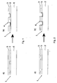
- the composite body 1 has the following structure:
- a metal foil 3 is provided, including a support body 2 in the form of a resin layer and below a plate-shaped base body. 6
- the pressing tool penetrates as far as the composite body 1 that a three-dimensional structure 4 is formed, in such a way that it extends through the metal foil 3 into the carrier body 2, here so into the resin layer.
- the base body 6 is not co-stamped.
- the composite body 1 consists only of a metal foil 3 and a support body 2 in the form of a resin layer.
- the embossed composite body 1 could then be adhered to any other materials.
- Fig. 2a finally shows an embodiment in which the composite body is constructed as follows:
- a metal foil 3 is also provided here as the uppermost layer, including a support body 2 in the form of a wood-based panel, wherein between the wood-based panel and the metal foil, an adhesive layer 5 is provided.
Landscapes
- Laminated Bodies (AREA)
- Chemical And Physical Treatments For Wood And The Like (AREA)
Abstract
Description
- Die Erfindung betrifft ein Verfahren zur Herstellung einer Strukturierung eines Verbundwerkstoffkörpers sowie einen entsprechenden Verbundwerkstoffkörper mit einem Trägerkörper und einer Metallfolie.
- Bei einem Verbundwerkstoffkörper, insbesondere einer Verbundplatte, kann es wünschenswert sein, einen Trägerkörper, insbesondere eine Holzwerkstoffplatte, mit einer dreidimensional strukturierten Metalloberfläche zu versehen. Eine derart strukturierte Metalloberfläche kann beispielsweise für rutschhemmende Böden eingesetzt werden. Es ist auch denkbar, durch eine Strukturierung der Metalloberfläche einer Verbundplatte oder eines anderen Verbundwerkstoffkörpers die Steifigkeit zu erhöhen. Auch aus optischen Gründen kann eine Strukturierung gewünscht sein.
- Aus dem Stand der Technik ist es bekannt, bei einem Verbundwerkstoffkörper, der als Basis eine Holzwerkstoffplatte hat, die Holzwerkstoffplatte zunächst mit einer Struktur zu versehen. Eine Struktur kann zum einen durch spanende Bearbeitung oder Prägen der Holzwerkstoffplatte selbst oder durch Aufkleben einer zuvor hergestellten, strukturierten Harzschicht hergestellt werden. Es ist auch bekannt, ein ein Kunstharz aufweisendes Laminat in einer Kurztaktpresse mit einem strukturierten Presswerkzeug aufzupressen. Anschließend wird auf die mit der Struktur versehene Holzwerkstoffplatte eine Metallfolie über die Struktur geklebt.
- Ein solches Herstellungsverfahren ist relativ aufwendig. So muss zunächst die Holzwerkstoffplatte strukturiert werden bzw. mit einer zuvor hergestellten Harz-Struktur beklebt werden. Anschließend muss die Metallfolie derart aufgebracht werden, dass sich die Strukturen durch die Metallfolie hindurchdrücken, also sichtbar und spürbar werden. Letzteres ist insbesondere bei relativ feinen Strukturen aber kaum möglich, so dass Bereiche der Strukturierung nach dem Aufkleben der Metallfolie nicht mehr sichtbar und spürbar sind.
- Der Erfindung liegt daher das technische Problem zugrunde, ein Verfahren zur Herstellung einer Strukturierung eines Verbundwerkstoffkörpers, wobei der Verbundwerkstoffkörper eine Metalloberfläche aufweisen soll, zu vereinfachen.
- Das zuvor aufgezeigte technische Problem wird erfindungsgemäß bei einem Verfahren zur Herstellung einer Strukturierung eines Verbundwerkstoffkörpers dadurch gelöst, dass eine Metallfolie mit einem eine dreidimensionale Struktur aufweisenden Presswerkzeug auf einen Trägerkörper gepresst wird, wobei der Pressdruck derart gewählt ist, dass beim Pressen die Struktur des Presswerkzeugs durch die Metallfolie hindurch in den Trägerkörper übertragen wird.
- Erfindungsgemäß ist erkannt worden, dass durch das erfindungsgemäße Verfahren, bei dem eine Metallfolie mit einem strukturierten Presswerkzeug in einen Trägerkörper gepresst wird, nur noch ein einziger Verfahrensschritt notwendig ist, um einen Verbundwerkstoffkörper herzustellen und diesen zu strukturieren. Es ist erfindungsgemäß nicht mehr erforderlich, zunächst eine Struktur auf oder in der Oberfläche eines Trägerkörpers vorzusehen und anschließend in einem weiteren Verfahrensschritt mühevoll eine Metallfolie darüber aufzubringen.
- Das erfindungsgemäße Verfahren hat auch den weiteren Vorteil, dass es in herkömmlichen Pressvorrichtungen durchführbar ist, beispielsweise in einer getakteten Anlage mit einem Pressstempel oder in einer kontinuierlich laufenden Anlage mit zum Beispiel Presswalzen und/oder Pressbändern. Es muss lediglich ein geeignetes Presswerkzeug eingespannt werden, welches die gewünschte Struktur aufweist.
- Überraschenderweise wurde festgestellt, dass durch das erfindungsgemäße Verfahren nicht nur eine Zeitersparnis erreicht wird, indem nur noch ein einziger Verfahrensschritt erforderlich ist, sondern es hat sich auch gezeigt, dass eine Struktur, die gleichzeitig durch die Metallfolie hindurch in den Trägerkörper eingeprägt wird, auch nach der Herstellung noch in allen Einzelheiten durch die Metallfolie hindurch sichtbar und spürbar ist. Durch das erfindungsgemäße Verfahren können also erstmalig auch relativ feine Strukturen dauerhaft und gut sichtbar und spürbar eingeprägt werden. Solche Strukturen können regelmäßig oder unregelmäßig, beispielsweise wellenförmig oder geriffelt, sogar in Form von Symbolen, Ornamenten oder Bildern, ausgebildet sein. Sie können auch derart ausgebildet sein, dass aus unterschiedlichen Blickwinkeln oder -richtungen andere Effekte sichtbar werden.
- Der Trägerkörper, auf den die Metallfolie aufgebracht wird, kann beliebige Formen haben und aus beliebigen Materialien bestehen. Vorzugsweise sollte das Material so gewählt sein, dass das Presswerkzeug beim Einprägen der Struktur relativ leicht in den Trägerkörper eindringen kann und die Struktur im Trägerkörper auch möglichst dauerhaft bestehen bleibt. Der Trägerkörper ist also idealerweise relativ weich und möglichst wenig elastisch.
- Gemäß einer bevorzugten Ausführungsform ist der Trägerkörper eine Platte, vorzugsweise eine Holzwerkstoffplatte, wobei zwischen der Metallfolie und dem Trägerkörper eine Kleberschicht aufgebracht ist. Insbesondere eine Holzwerkstoffplatte eignet sich für das erfindungsgemäße Herstellungsverfahren, da ein solcher Werkstoff relativ weich ist und gerade so wenig elastisch ist, dass eingeprägte Strukturen dauerhaft bestehen bleiben.
- Mit einer Holzwerkstoffplatte im Sinne der Erfindung ist jegliche Form von Partikel- oder Faserplatten wie zum Beispiel mitteldichte Faserplatten (MDF), hochdichte Faserplatten (HDF) oder Faserplatten von sehr geringer Dichte (LDF) gemeint. Auch Spanplatten oder OSB-Platten (Oriented-Strands-Board) fallen unter den Begriff Holzwerkstoffplatte. Es ist auch denkbar, eine Holzwerkstoffplatte aus mehreren, miteinander verklebten Einzelplatten vorzusehen.
- Es ist denkbar, dass die Kleberschicht eine Harzschicht ist, insbesondere mit einem Duroplastharz, Aminoplastharz oder Harz auf Melamin- oder Phenolbasis.
- Gemäß einer weiteren bevorzugten Ausführungsform ist der Trägerkörper nicht eine Platte, auf die ein Kleber bzw. Harz aufgebracht wird, wie es zuvor beschrieben wurde, sondern der Trägerkörper ist selbst gebildet durch eine Harzschicht, insbesondere mit einem Duroplastharz, Aminoplastharz oder Harz auf Melamin- oder Phenolbasis. Es ist also denkbar, beim Prägen mit dem erfindungsgemäßen Verfahren eine Metallfolie in eine Harzschicht einzuprägen, wobei die dreidimensionale Struktur durch die Metallfolie hindurch in den Trägerkörper, also in das Harz, reicht- Anschließend kann der so hergestellte, strukturierte Körper beliebig weiterverarbeitet werden, beispielsweise durch Aufkleben auf eine weitere Platte oder einen anderen Körper. Es ist auch denkbar, beim Pressen unter dem Trägerkörper, das heißt dem Harz, einen Grundkörper vorzusehen. Der Druck des Presswerkzeugs wäre dann so zu wählen, dass der Grundkörper nicht mitstrukturiert wird.
- Alternativ ist aber auch denkbar, einen verbund aus Metallfolie, Trägerkörper, beispielsweise Holzwerkstoffplatte, und dazwischen angeordneter Kleber- oder Harzschicht in die Pressvorrichtung zu führen, wobei der Pressdruck des Presswerkzeugs die dreidimensionale Struktur durch die Metallfolie hindurch bis in den Trägerkörper, beispielsweise die Holzwerkstoffplatte, prägt.
- Die Kleber- oder Harzschicht, die als Trägerkörper oder als Kleberschicht zwischen Trägerkörper und Metallfolie dient, kann aus einem oder mehreren kleber- oder harzgetränkten Papieren bestehen oder ein oder mehrere kleber- oder harzgetränkte Papiere aufweisen, die gegebenenfalls vorkondensiert bzw. getrocknet sind.
- Vorzugsweise weist die Metallfolie, die zum besseren Verbinden mit einem Primer versehen sein kann, eine oder mehrere der Metalle Aluminium, Messing, Kupfer, Bronze, Silber oder Gold oder Legierung davon aus. Selbstverständlich sind abhängig von der Zweckbestimmung auch andere Metalle denkbar. Beispielsweise ist neben einem sehr weichen Material wie Aluminium auch ein relativ hartes Material wie Titan denkbar. Allerdings ist darauf zu achten, dass bei einer ungünstigen Struktur im Presswerkzeug ein hartes Folienmaterial schnell reißen kann. Bei besonders hartem Folienmaterial kann auch das Presswerkzeug schnell verschleißen. Es ist daher immer günstig, das Material des Trägerkörpers, das Material der Metallfolie und die Form bzw. Ausgestaltung des Presswerkzeugs, insbesondere auch sein Material, derart aufeinander abzustimmen, dass die Metallfolie und/oder das Presswerkzeug unbeschädigt bleibt.
- Die Metallfolie kann vor oder nach dem Pressen oberflächenbehandelt werden. Insbesondere ist dabei an ein Eloxieren, ein Beschichten oder ein Bedrucken zu denken. Auch ein Bedampfen, ein Ätzen oder ein Lackieren sind denkbare Methoden zur vorherigen oder weiteren Oberflächenbehandlung.
- Das aufgezeigte technische Problem wird erfindungsgemäß auch bei einem Verbundwerkstoffkörper mit einem Trägerkörper und einer Metallfolie, der insbesondere nach dem zuvor beschriebenen Verfahren hergestellt und strukturiert wurde, dadurch gelöst, dass der Trägerkörper mit einer aufgepressten Metallfolie verbunden ist, wobei eine dreidimensionale Struktur im Verbundwerkstoffkörper vorgesehen ist, die durch die Metallfolie hindurch in den Trägerkörper reicht.
- Wie bereits zuvor angedeutet, kommt es bei dem Verbundwerkstoffkörper darauf an, dass nach dem Pressvorgang sowohl im Trägerkörper als auch in der Metallfolie die dreidimensionale Struktur sichtbar und spürbar ist. Bei dem Trägerkörper kann es sich, wie gesagt, um eine Platte handeln, wobei sich dann eine Kleberschicht zwischen Metallfolie und Platte befindet, so dass bei gleichzeitigem Einführen von Metallfolie, Kleberschicht und Trägerkörper in die Pressvorrichtung die dreidimensionale Struktur durch die Metallfolie hindurch in den Trägerkörper, beispielsweise in die Holzwerkstoffplatte, reicht.
- Ebenso ist es denkbar, dass der Trägerkörper eine Kleber- oder Harzschicht ist, so dass folglich nach dem Pressvorgang die dreidimensionale Struktur durch die Metallfolie hindurch nur bis in die Kleber- oder Harzschicht reicht.
- Der erfindungsgemäße Verbundwerkstoffkörper kann neben dem Trägerkörper und der Metallfolie selbstverständlich auch noch einen weiteren, unter dem Trägerkörper angebrachten Grundkörper, beispielsweise einer weiteren Platte, aufweisen. Auch kann sich unter dem Trägerkörper und/oder dem Grundkörper eine weitere Beschichtung, vorzugsweise ein Gegenzug, der ein Verformen oder Verziehen verhindert, vorgesehen sein. Dementsprechend kann bei dem Verfahren zur Herstellung einer Strukturierung gemäß der vorliegenden Erfindung neben der Metallfolie und dem Trägerkörper, beispielsweise der Kleber- oder Harzschicht, also zumindest noch ein weiterer Körper, beispielsweise eine Grundplatte, vorzugsweise ein Holzwerkstoffplatte, in die Pressvorrichtung eingeführt werden. In dem Fall, in dem der Trägerkörper eine Kleber- oder Harzschicht ist, kann also der Verbundwerkstoffkörper, welcher durch das Pressen strukturiert wird, aus einem Grundkörper, einer Kleber- oder Harzschicht und einer Metallfolie bestehen oder aber nur aus einer Kleber- oder Harzschicht und einer Metallfolie. In dem Fall, in dem der Trägerkörper eine Platte ist, besteht der Verbundwerkstoffkörper zumindest aus dem Trägerkörper, einer Metallfolie und einer dazwischen angeordneten Kleberschicht, die auch eine Harzschicht sein kann.
- Selbstverständlich ist es auch denkbar, den zuvor beschriebenen Aufbau des Verbundwerkstoffkörpers beidseitig vorzusehen, so dass auf einen Trägerkörper beidseitig eine Metallfolie aufgepresst wird bzw. aufgepresst ist.
- Es gibt nun eine Vielzahl von Möglichkeiten, das erfindungsgemäße Verfahren und den erfindungsgemäßen Verbundwerkstoffkörper auszugestalten und weiterzubilden. Hierzu wird beispielsweise verwiesen einerseits auf die dem Patentanspruch 1 und dem Patentanspruch 9 jeweils nachgeordneten Patentansprüche, andererseits auf die Beschreibung eines Ausführungsbeispiels in Verbindung mit der Zeichnung. In der Zeichnung zeigen:
- Figuren 1a) und b)
- die Herstellung eines ersten Ausführungsbeispiels eines erfindungsgemäßen Verbundwerkstoffkörpers und
- Figuren 2a) und b)
- die Herstellung eines zweiten Ausführungsbeispiels eines erfindungsgemäßen Verbundwerkstoffkörpers und
- Fig. 1a) zeigt die einzelnen Schichten eines herzustellenden und zu strukturierenden Verbundwerkstoffkörpers 1, vor einem Pressvorgang, bei dem ein Presswerkzeug eine Struktur 4 einprägt. Im Ausführungsbeispiel in Figur 1a) und b) hat der Verbundwerkstoffkörper 1 den folgenden Aufbau:
- Als oberste Schicht ist eine Metallfolie 3 vorgesehen, darunter ein Trägerkörper 2 in Form einer Harzschicht und darunter ein plattenförmiger Grundkörper 6.
- Während des Pressvorgangs dringt das Presswerkzeug soweit in den Verbundwerkstoffkörper 1 ein, dass eine dreidimensionale Struktur 4 entsteht, und zwar derart, dass sie durch die Metallfolie 3 hindurch in den Trägerkörper 2, hier also bis in die Harzschicht, reicht. Der Grundkörper 6 wird dabei nicht mitgeprägt.
- Selbstverständlich kann bei dem Pressvorgang auch auf eine Grundplatte 6 verzichtet werden, so dass der Verbundwerkstoffkörper 1 nur aus einer Metallfolie 3 und einem Trägerkörper 2 in Form einer Harzschicht besteht. Der geprägte Verbundwerkstoffkörper 1 könnte anschließend auf beliebige andere Materialien aufgeklebt werden.
- Fig. 2a) zeigt schließlich ein Ausführungsbeispiel, bei dem der Verbundwerkstoffkörper wie folgt aufgebaut ist:
- Zunächst ist auch hier als oberste Schicht eine Metallfolie 3 vorgesehen, darunter ein Trägerkörper 2 in Form einer Holzwerkstoffplatte, wobei zwischen der Holzwerkstoffplatte und der Metallfolie eine Kleberschicht 5 vorgesehen ist.
- In Fig. 2b) ist zu erkennen, dass der Pressdruck auch bei diesem Ausführungsbeispiel derart gewählt ist, dass beim Pressen die Struktur 4 durch die Metallfolie 3 hindurch in den Trägerkörper 2 übertragen wird, und zwar durch die Kleberschicht 5 hindurch.
Claims (16)
- Verfahren zur Herstellung einer Strukturierung eines Verbundwerkstoffkörpers, dadurch gekennzeichnet, dass eine Metallfolie mit einem eine dreidimensionale Struktur aufweisenden Presswerkzeug auf einen Trägerkörper gepresst wird, wobei der Pressdruck derart gewählt ist, dass beim Pressen die Struktur des Presswerkzeugs durch die Metallfolie hindurch in den Trägerkörper übertragen wird.
- Verfahren nach Anspruch 1, dadurch gekennzeichnet, dass der Trägerkörper eine Platte ist, vorzugsweise eine Holzwerkstoffplatte, wobei zwischen der Metallfolie und dem Trägerkörper eine Kleberschicht aufgebracht wird.
- Verfahren nach Anspruch 2, dadurch gekennzeichnet, dass die Kleberschicht eine Harzschicht ist, insbesondere mit einem Duroplastharz, Aminoplastharz oder Harz auf Melamin- oder Phenolbasis.
- Verfahren nach Anspruch 1, dadurch gekennzeichnet, dass der Trägerkörper eine Kleber- oder Harzschicht ist, insbesondere mit einem Duroplastharz, Aminoplastharz oder Harz auf Melamin- oder Phenolbasis.
- Verfahren nach Anspruch 3 oder 4, dadurch gekennzeichnet, dass die Kleber- oder Harzschicht ein oder mehrere kleber- oder harzgetränkte Papiere aufweist.
- Verfahren nach einem der Ansprüche 1 bis 5, dadurch gekennzeichnet, dass die Metallfolie eines oder mehrere der Metalle Aluminium, Messing, Kupfer, Bronze, Silber oder Gold oder Legierungen davon aufweist.
- Verfahren nach einem der Ansprüche 1 bis 6, dadurch gekennzeichnet, dass beim Pressen eine regelmäßige oder unregelmäßige, insbesondere wellenförmige oder geriffelte, Struktur erzeugt wird.
- Verfahren nach einem der Ansprüche 1 bis 7, dadurch gekennzeichnet, dass die Metallfolie vor oder nach dem Pressen oberflächenbehandelt, insbesondere eloxiert, beschichtet oder bedruckt, wird.
- Verbundwerkstoffkörper (1) mit einem Trägerkörper (2) und einer Metallfolie (3), insbesondere hergestellt und strukturiert nach einem Verfahren nach einem der Ansprüche 1 bis 8, dadurch gekennzeichnet, dass der Trägerkörper (2) mit einer aufgepressten Metallfolie (3) verbunden ist, wobei eine dreidimensionale Struktur (4) im Verbundwerkstoffkörper vorgesehen ist, die durch die Metallfolie (3) hindurch in den Trägerkörper (2) reicht.
- Verbundwerkstoffkörper (1) nach Anspruch 9, dadurch gekennzeichnet, dass der Trägerkörper (2) eine Platte ist, vorzugsweise eine Holzwerkstoffplatte, wobei zwischen der Metallfolie (3) und dem Trägerkörper (2) eine Kleberschicht (5) vorgesehen ist.
- Verbundwerkstoffkörper (1) nach Anspruch 10, dadurch gekennzeichnet, dass die Kleberschicht (5) eine Kleber- oder Harzschicht ist, insbesondere mit einem Duroplastharz, Aminoplastharz oder Harz auf Melamin- oder Phenolbasis.
- Verbundwerkstoffkörper (1) nach Anspruch 9, dadurch gekennzeichnet, dass der Trägerkörper (2) eine Kleber- oder Harzschicht ist, insbesondere mit einem Duroplastharz, Aminoplastharz oder Harz auf Melamin- oder Phenolbasis.
- Verbundwerkstoffkörper (1) nach Anspruch 11 oder 12, dadurch gekennzeichnet, dass die Kleber- oder Harzschicht ein oder mehrere kleber- oder harzgetränkte Papiere aufweist.
- Verbundwerkstoffkörper (1) nach einem der Ansprüche 9 bis 13, dadurch gekennzeichnet, dass die Metallfolie (3) eines oder mehrere der Metalle Aluminium, Messing, Kupfer, Bronze, Silber oder Gold oder Legierungen davon aufweist.
- Verbundwerkstoffkörper (1) nach einem der Ansprüche 9 bis 14, dadurch gekennzeichnet, dass die Struktur im Verbundwerkstoffkörper (1) regelmäßig oder unregelmäßig, insbesondere wellenförmig oder geriffelt, ausgebildet ist.
- Verbundwerkstoffkörper (1) nach einem der Ansprüche 9 bis 15, dadurch gekennzeichnet, dass die Metallfolie (3) oberflächenbehandelt, insbesondere eloxiert, beschichtet oder bedruckt, ist.
Priority Applications (1)
| Application Number | Priority Date | Filing Date | Title |
|---|---|---|---|
| PL05012814T PL1621334T3 (pl) | 2004-07-30 | 2005-06-15 | Sposób wytwarzania strukturyzowania przedmiotu z tworzywa wielowarstwowego |
Applications Claiming Priority (1)
| Application Number | Priority Date | Filing Date | Title |
|---|---|---|---|
| DE102004037400A DE102004037400A1 (de) | 2004-07-30 | 2004-07-30 | Verfahren zur Herstellung einer Strukturierung eines Verbundwerkstoffkörpers |
Publications (3)
| Publication Number | Publication Date |
|---|---|
| EP1621334A2 true EP1621334A2 (de) | 2006-02-01 |
| EP1621334A3 EP1621334A3 (de) | 2006-08-23 |
| EP1621334B1 EP1621334B1 (de) | 2009-08-05 |
Family
ID=35529891
Family Applications (1)
| Application Number | Title | Priority Date | Filing Date |
|---|---|---|---|
| EP05012814A Expired - Lifetime EP1621334B1 (de) | 2004-07-30 | 2005-06-15 | Verfahren zur Herstellung einer Strukturierung eines Verbundwerkstoffkörpers |
Country Status (5)
| Country | Link |
|---|---|
| EP (1) | EP1621334B1 (de) |
| AT (1) | ATE438506T1 (de) |
| DE (2) | DE102004037400A1 (de) |
| ES (1) | ES2328366T3 (de) |
| PL (1) | PL1621334T3 (de) |
Cited By (2)
| Publication number | Priority date | Publication date | Assignee | Title |
|---|---|---|---|---|
| RU2620427C1 (ru) * | 2014-03-24 | 2017-05-25 | Ниссин Стил Ко., Лтд. | Толстый лист металла с покрытием и конструкционный материал для наружного использования |
| EP3245076B1 (de) | 2015-01-16 | 2020-12-23 | Fritz Egger GmbH & Co. OG | Bauelement mit durch prägen erzeugter oberflächenstruktur und verfahren zu dessen herstellung |
Family Cites Families (7)
| Publication number | Priority date | Publication date | Assignee | Title |
|---|---|---|---|---|
| US2830001A (en) * | 1956-08-01 | 1958-04-08 | Foil Process Corp | Directionally-oriented tearing metal foil sheet material |
| US3180779A (en) * | 1962-11-14 | 1965-04-27 | Congoleum Nairn Inc | Decorative surface coverings and process for producing them |
| DE2214178A1 (de) * | 1972-03-23 | 1973-11-15 | Tropimex Ag | Verfahren zum herstellen von leichten verbundplatten sowie verbundplatte |
| DE2438104C3 (de) * | 1974-08-08 | 1982-07-08 | Hpw Herzberger Plattenwerke Gmbh & Co Kg, 3420 Herzberg | Verfahren zur Herstellung dekorativer Schichtpreßstofftafeln |
| CH683605A5 (de) * | 1992-04-22 | 1994-04-15 | Maloya Ag | Verfahren zur Herstellung von Metall-Elastomer-Schichtverbundkörpern. |
| DE19924604B4 (de) * | 1999-05-28 | 2005-06-30 | Faist Automotive Gmbh & Co. Kg | Verfahren zur Herstellung eines dreidimensionalen Formkörpers |
| DE10007621A1 (de) * | 2000-02-18 | 2001-08-23 | Dekodur Gmbh & Co Kg | Verfahren zur Herstellung dekorativer plattenförmiger Verbundwerkstoffe mit Reliefstruktur |
-
2004
- 2004-07-30 DE DE102004037400A patent/DE102004037400A1/de not_active Withdrawn
-
2005
- 2005-06-15 PL PL05012814T patent/PL1621334T3/pl unknown
- 2005-06-15 EP EP05012814A patent/EP1621334B1/de not_active Expired - Lifetime
- 2005-06-15 ES ES05012814T patent/ES2328366T3/es not_active Expired - Lifetime
- 2005-06-15 DE DE502005007829T patent/DE502005007829D1/de not_active Expired - Lifetime
- 2005-06-15 AT AT05012814T patent/ATE438506T1/de active
Cited By (2)
| Publication number | Priority date | Publication date | Assignee | Title |
|---|---|---|---|---|
| RU2620427C1 (ru) * | 2014-03-24 | 2017-05-25 | Ниссин Стил Ко., Лтд. | Толстый лист металла с покрытием и конструкционный материал для наружного использования |
| EP3245076B1 (de) | 2015-01-16 | 2020-12-23 | Fritz Egger GmbH & Co. OG | Bauelement mit durch prägen erzeugter oberflächenstruktur und verfahren zu dessen herstellung |
Also Published As
| Publication number | Publication date |
|---|---|
| ATE438506T1 (de) | 2009-08-15 |
| EP1621334B1 (de) | 2009-08-05 |
| EP1621334A3 (de) | 2006-08-23 |
| ES2328366T3 (es) | 2009-11-12 |
| PL1621334T3 (pl) | 2010-01-29 |
| DE102004037400A1 (de) | 2006-03-23 |
| DE502005007829D1 (de) | 2009-09-17 |
Similar Documents
| Publication | Publication Date | Title |
|---|---|---|
| DE69716714T2 (de) | Verfahren zur oberflächenstrukturierung | |
| EP2540520B1 (de) | Laminierte Dekorplatte | |
| EP1985464B1 (de) | Bauplatte, insbesondere Fußbodenpaneel, und Verfahren zu deren Herstellung | |
| DE69713572T2 (de) | Ein verfahren zur herstellung einer dekorativen beschichtung | |
| EP2197594A2 (de) | Verfahren zum herstellen eines fussbodenpaneels mit hoher rutschfestigkeit | |
| DE102016104432B4 (de) | Verfahren zur Herstellung von Reliefplatten | |
| EP2493684A1 (de) | Verfahren zur herstellung eines pressblechs, verfahren zur herstellung einer pressblechanordnung sowie pressblechanordnung | |
| EP1961533A1 (de) | Verfahren zum Anhaften von Kantenmaterial an Leichtbauplatten | |
| EP0370353A2 (de) | Verfahren zur Herstellung eines Postforming-Laminats | |
| DE102006052555B3 (de) | Verfahren zur Herstellung eines Paneels mit einer strukturierten Oberfläche | |
| EP1621334B1 (de) | Verfahren zur Herstellung einer Strukturierung eines Verbundwerkstoffkörpers | |
| EP3666514A1 (de) | Pressblech zum erzeugen tiefer strukturen | |
| EP0842791B1 (de) | Vorrichtung zur Herstellung einer bündigen Prägestruktur auf Datenträgern | |
| DE3220768C2 (de) | Verfahren zum Herstellen von mit einer strukturierten Dekorschicht versehenen Formteilen aus Faservliesen | |
| DE10317271A1 (de) | Schichtplatte | |
| DE10102146C1 (de) | Verbundzierteil | |
| EP1616680B1 (de) | Verfahren zur Herstellung von Holzelementen mit einer eine Naturholzmaserung nachbildenden Maserung | |
| DE102011081075A1 (de) | Verfahren zur Herstellung von plattenförmigen Werkstücken | |
| DE19902673A1 (de) | Verfahren zur Herstellung einer auf Holzwerkstoff basierenden Schichtplatte sowie Schichtplatte und Holzwerkstoffplatte | |
| DE102017112549A1 (de) | Verfahren zum Herstellen einer Verbundplatte und Verbundplatte | |
| DE3609239A1 (de) | Verfahren zur herstellung einer plattenartigen matrize | |
| DE3518510A1 (de) | Verfahren zur herstellung einer pressplatte und nach diesem verfahren hergestellte pressplatte | |
| WO2023198551A1 (de) | Oberflächenbeschichtung sowie herstellungsverfahren | |
| DE10018875C5 (de) | Verfahren zur Herstellung einer Verbundplatte | |
| DE102022125371A1 (de) | Presswerkzeug zum Verpressen von Werkstoffplatten in Heizpressen |
Legal Events
| Date | Code | Title | Description |
|---|---|---|---|
| PUAI | Public reference made under article 153(3) epc to a published international application that has entered the european phase |
Free format text: ORIGINAL CODE: 0009012 |
|
| AK | Designated contracting states |
Kind code of ref document: A2 Designated state(s): AT BE BG CH CY CZ DE DK EE ES FI FR GB GR HU IE IS IT LI LT LU MC NL PL PT RO SE SI SK TR |
|
| AX | Request for extension of the european patent |
Extension state: AL BA HR LV MK YU |
|
| PUAL | Search report despatched |
Free format text: ORIGINAL CODE: 0009013 |
|
| AK | Designated contracting states |
Kind code of ref document: A3 Designated state(s): AT BE BG CH CY CZ DE DK EE ES FI FR GB GR HU IE IS IT LI LT LU MC NL PL PT RO SE SI SK TR |
|
| AX | Request for extension of the european patent |
Extension state: AL BA HR LV MK YU |
|
| 17P | Request for examination filed |
Effective date: 20060920 |
|
| AKX | Designation fees paid |
Designated state(s): AT BE BG CH CY CZ DE DK EE ES FI FR GB GR HU IE IS IT LI LT LU MC NL PL PT RO SE SI SK TR |
|
| AXX | Extension fees paid |
Extension state: LV Payment date: 20060920 Extension state: HR Payment date: 20060920 Extension state: BA Payment date: 20060920 |
|
| 17Q | First examination report despatched |
Effective date: 20071019 |
|
| GRAP | Despatch of communication of intention to grant a patent |
Free format text: ORIGINAL CODE: EPIDOSNIGR1 |
|
| GRAS | Grant fee paid |
Free format text: ORIGINAL CODE: EPIDOSNIGR3 |
|
| GRAA | (expected) grant |
Free format text: ORIGINAL CODE: 0009210 |
|
| AK | Designated contracting states |
Kind code of ref document: B1 Designated state(s): AT BE BG CH CY CZ DE DK EE ES FI FR GB GR HU IE IS IT LI LT LU MC NL PL PT RO SE SI SK TR |
|
| AX | Request for extension of the european patent |
Extension state: BA HR LV |
|
| REG | Reference to a national code |
Ref country code: GB Ref legal event code: FG4D Free format text: NOT ENGLISH |
|
| REG | Reference to a national code |
Ref country code: CH Ref legal event code: EP Ref country code: CH Ref legal event code: NV Representative=s name: TROESCH SCHEIDEGGER WERNER AG |
|
| REG | Reference to a national code |
Ref country code: IE Ref legal event code: FG4D |
|
| REG | Reference to a national code |
Ref country code: RO Ref legal event code: EPE |
|
| REF | Corresponds to: |
Ref document number: 502005007829 Country of ref document: DE Date of ref document: 20090917 Kind code of ref document: P |
|
| REG | Reference to a national code |
Ref country code: ES Ref legal event code: FG2A Ref document number: 2328366 Country of ref document: ES Kind code of ref document: T3 |
|
| REG | Reference to a national code |
Ref country code: SE Ref legal event code: TRGR |
|
| LTIE | Lt: invalidation of european patent or patent extension |
Effective date: 20090805 |
|
| PG25 | Lapsed in a contracting state [announced via postgrant information from national office to epo] |
Ref country code: FI Free format text: LAPSE BECAUSE OF FAILURE TO SUBMIT A TRANSLATION OF THE DESCRIPTION OR TO PAY THE FEE WITHIN THE PRESCRIBED TIME-LIMIT Effective date: 20090805 Ref country code: LT Free format text: LAPSE BECAUSE OF FAILURE TO SUBMIT A TRANSLATION OF THE DESCRIPTION OR TO PAY THE FEE WITHIN THE PRESCRIBED TIME-LIMIT Effective date: 20090805 Ref country code: IS Free format text: LAPSE BECAUSE OF FAILURE TO SUBMIT A TRANSLATION OF THE DESCRIPTION OR TO PAY THE FEE WITHIN THE PRESCRIBED TIME-LIMIT Effective date: 20091205 |
|
| REG | Reference to a national code |
Ref country code: PL Ref legal event code: T3 |
|
| NLV1 | Nl: lapsed or annulled due to failure to fulfill the requirements of art. 29p and 29m of the patents act | ||
| PG25 | Lapsed in a contracting state [announced via postgrant information from national office to epo] |
Ref country code: SI Free format text: LAPSE BECAUSE OF FAILURE TO SUBMIT A TRANSLATION OF THE DESCRIPTION OR TO PAY THE FEE WITHIN THE PRESCRIBED TIME-LIMIT Effective date: 20090805 Ref country code: NL Free format text: LAPSE BECAUSE OF FAILURE TO SUBMIT A TRANSLATION OF THE DESCRIPTION OR TO PAY THE FEE WITHIN THE PRESCRIBED TIME-LIMIT Effective date: 20090805 |
|
| REG | Reference to a national code |
Ref country code: IE Ref legal event code: FD4D |
|
| PG25 | Lapsed in a contracting state [announced via postgrant information from national office to epo] |
Ref country code: BG Free format text: LAPSE BECAUSE OF FAILURE TO SUBMIT A TRANSLATION OF THE DESCRIPTION OR TO PAY THE FEE WITHIN THE PRESCRIBED TIME-LIMIT Effective date: 20091105 Ref country code: PT Free format text: LAPSE BECAUSE OF FAILURE TO SUBMIT A TRANSLATION OF THE DESCRIPTION OR TO PAY THE FEE WITHIN THE PRESCRIBED TIME-LIMIT Effective date: 20091205 |
|
| PG25 | Lapsed in a contracting state [announced via postgrant information from national office to epo] |
Ref country code: EE Free format text: LAPSE BECAUSE OF FAILURE TO SUBMIT A TRANSLATION OF THE DESCRIPTION OR TO PAY THE FEE WITHIN THE PRESCRIBED TIME-LIMIT Effective date: 20090805 Ref country code: DK Free format text: LAPSE BECAUSE OF FAILURE TO SUBMIT A TRANSLATION OF THE DESCRIPTION OR TO PAY THE FEE WITHIN THE PRESCRIBED TIME-LIMIT Effective date: 20090805 Ref country code: IE Free format text: LAPSE BECAUSE OF FAILURE TO SUBMIT A TRANSLATION OF THE DESCRIPTION OR TO PAY THE FEE WITHIN THE PRESCRIBED TIME-LIMIT Effective date: 20090805 Ref country code: CZ Free format text: LAPSE BECAUSE OF FAILURE TO SUBMIT A TRANSLATION OF THE DESCRIPTION OR TO PAY THE FEE WITHIN THE PRESCRIBED TIME-LIMIT Effective date: 20090805 |
|
| PG25 | Lapsed in a contracting state [announced via postgrant information from national office to epo] |
Ref country code: SK Free format text: LAPSE BECAUSE OF FAILURE TO SUBMIT A TRANSLATION OF THE DESCRIPTION OR TO PAY THE FEE WITHIN THE PRESCRIBED TIME-LIMIT Effective date: 20090805 |
|
| PLBE | No opposition filed within time limit |
Free format text: ORIGINAL CODE: 0009261 |
|
| STAA | Information on the status of an ep patent application or granted ep patent |
Free format text: STATUS: NO OPPOSITION FILED WITHIN TIME LIMIT |
|
| 26N | No opposition filed |
Effective date: 20100507 |
|
| PG25 | Lapsed in a contracting state [announced via postgrant information from national office to epo] |
Ref country code: GR Free format text: LAPSE BECAUSE OF FAILURE TO SUBMIT A TRANSLATION OF THE DESCRIPTION OR TO PAY THE FEE WITHIN THE PRESCRIBED TIME-LIMIT Effective date: 20091106 |
|
| PG25 | Lapsed in a contracting state [announced via postgrant information from national office to epo] |
Ref country code: MC Free format text: LAPSE BECAUSE OF NON-PAYMENT OF DUE FEES Effective date: 20100630 |
|
| PG25 | Lapsed in a contracting state [announced via postgrant information from national office to epo] |
Ref country code: CY Free format text: LAPSE BECAUSE OF FAILURE TO SUBMIT A TRANSLATION OF THE DESCRIPTION OR TO PAY THE FEE WITHIN THE PRESCRIBED TIME-LIMIT Effective date: 20090805 |
|
| PG25 | Lapsed in a contracting state [announced via postgrant information from national office to epo] |
Ref country code: HU Free format text: LAPSE BECAUSE OF FAILURE TO SUBMIT A TRANSLATION OF THE DESCRIPTION OR TO PAY THE FEE WITHIN THE PRESCRIBED TIME-LIMIT Effective date: 20100206 Ref country code: LU Free format text: LAPSE BECAUSE OF NON-PAYMENT OF DUE FEES Effective date: 20100615 |
|
| REG | Reference to a national code |
Ref country code: FR Ref legal event code: PLFP Year of fee payment: 12 |
|
| REG | Reference to a national code |
Ref country code: FR Ref legal event code: PLFP Year of fee payment: 13 |
|
| REG | Reference to a national code |
Ref country code: FR Ref legal event code: PLFP Year of fee payment: 14 |
|
| PGFP | Annual fee paid to national office [announced via postgrant information from national office to epo] |
Ref country code: SE Payment date: 20220623 Year of fee payment: 18 Ref country code: RO Payment date: 20220517 Year of fee payment: 18 Ref country code: IT Payment date: 20220620 Year of fee payment: 18 Ref country code: GB Payment date: 20220623 Year of fee payment: 18 |
|
| PGFP | Annual fee paid to national office [announced via postgrant information from national office to epo] |
Ref country code: TR Payment date: 20220506 Year of fee payment: 18 Ref country code: PL Payment date: 20220505 Year of fee payment: 18 Ref country code: BE Payment date: 20220623 Year of fee payment: 18 Ref country code: AT Payment date: 20220622 Year of fee payment: 18 |
|
| PGFP | Annual fee paid to national office [announced via postgrant information from national office to epo] |
Ref country code: FR Payment date: 20220623 Year of fee payment: 18 |
|
| PGFP | Annual fee paid to national office [announced via postgrant information from national office to epo] |
Ref country code: ES Payment date: 20220805 Year of fee payment: 18 Ref country code: DE Payment date: 20220623 Year of fee payment: 18 |
|
| PGFP | Annual fee paid to national office [announced via postgrant information from national office to epo] |
Ref country code: CH Payment date: 20220623 Year of fee payment: 18 |
|
| REG | Reference to a national code |
Ref country code: DE Ref legal event code: R119 Ref document number: 502005007829 Country of ref document: DE |
|
| REG | Reference to a national code |
Ref country code: SE Ref legal event code: EUG |
|
| PG25 | Lapsed in a contracting state [announced via postgrant information from national office to epo] |
Ref country code: RO Free format text: LAPSE BECAUSE OF NON-PAYMENT OF DUE FEES Effective date: 20230615 |
|
| REG | Reference to a national code |
Ref country code: CH Ref legal event code: PL |
|
| REG | Reference to a national code |
Ref country code: AT Ref legal event code: MM01 Ref document number: 438506 Country of ref document: AT Kind code of ref document: T Effective date: 20230615 |
|
| REG | Reference to a national code |
Ref country code: BE Ref legal event code: MM Effective date: 20230630 |
|
| GBPC | Gb: european patent ceased through non-payment of renewal fee |
Effective date: 20230615 |
|
| PG25 | Lapsed in a contracting state [announced via postgrant information from national office to epo] |
Ref country code: AT Free format text: LAPSE BECAUSE OF NON-PAYMENT OF DUE FEES Effective date: 20230615 |
|
| PG25 | Lapsed in a contracting state [announced via postgrant information from national office to epo] |
Ref country code: DE Free format text: LAPSE BECAUSE OF NON-PAYMENT OF DUE FEES Effective date: 20240103 Ref country code: AT Free format text: LAPSE BECAUSE OF NON-PAYMENT OF DUE FEES Effective date: 20230615 Ref country code: CH Free format text: LAPSE BECAUSE OF NON-PAYMENT OF DUE FEES Effective date: 20230630 Ref country code: GB Free format text: LAPSE BECAUSE OF NON-PAYMENT OF DUE FEES Effective date: 20230615 |
|
| PG25 | Lapsed in a contracting state [announced via postgrant information from national office to epo] |
Ref country code: SE Free format text: LAPSE BECAUSE OF NON-PAYMENT OF DUE FEES Effective date: 20230616 Ref country code: FR Free format text: LAPSE BECAUSE OF NON-PAYMENT OF DUE FEES Effective date: 20230630 Ref country code: BE Free format text: LAPSE BECAUSE OF NON-PAYMENT OF DUE FEES Effective date: 20230630 |
|
| REG | Reference to a national code |
Ref country code: ES Ref legal event code: FD2A Effective date: 20240730 |
|
| PG25 | Lapsed in a contracting state [announced via postgrant information from national office to epo] |
Ref country code: IT Free format text: LAPSE BECAUSE OF NON-PAYMENT OF DUE FEES Effective date: 20230615 |
|
| PG25 | Lapsed in a contracting state [announced via postgrant information from national office to epo] |
Ref country code: ES Free format text: LAPSE BECAUSE OF NON-PAYMENT OF DUE FEES Effective date: 20230616 |
|
| PG25 | Lapsed in a contracting state [announced via postgrant information from national office to epo] |
Ref country code: PL Free format text: LAPSE BECAUSE OF NON-PAYMENT OF DUE FEES Effective date: 20230615 |
|
| PG25 | Lapsed in a contracting state [announced via postgrant information from national office to epo] |
Ref country code: PL Free format text: LAPSE BECAUSE OF NON-PAYMENT OF DUE FEES Effective date: 20230615 Ref country code: ES Free format text: LAPSE BECAUSE OF NON-PAYMENT OF DUE FEES Effective date: 20230616 |