EP1619293A2 - Herstellung eines Papiermachergewebes - Google Patents
Herstellung eines Papiermachergewebes Download PDFInfo
- Publication number
- EP1619293A2 EP1619293A2 EP05104982A EP05104982A EP1619293A2 EP 1619293 A2 EP1619293 A2 EP 1619293A2 EP 05104982 A EP05104982 A EP 05104982A EP 05104982 A EP05104982 A EP 05104982A EP 1619293 A2 EP1619293 A2 EP 1619293A2
- Authority
- EP
- European Patent Office
- Prior art keywords
- dry material
- selected areas
- applying
- molten
- charged
- Prior art date
- Legal status (The legal status is an assumption and is not a legal conclusion. Google has not performed a legal analysis and makes no representation as to the accuracy of the status listed.)
- Withdrawn
Links
Images

Classifications
-
- D—TEXTILES; PAPER
- D21—PAPER-MAKING; PRODUCTION OF CELLULOSE
- D21F—PAPER-MAKING MACHINES; METHODS OF PRODUCING PAPER THEREON
- D21F1/00—Wet end of machines for making continuous webs of paper
- D21F1/0027—Screen-cloths
-
- D—TEXTILES; PAPER
- D21—PAPER-MAKING; PRODUCTION OF CELLULOSE
- D21F—PAPER-MAKING MACHINES; METHODS OF PRODUCING PAPER THEREON
- D21F1/00—Wet end of machines for making continuous webs of paper
- D21F1/0027—Screen-cloths
- D21F1/0063—Perforated sheets
Definitions
- This invention relates to the manufacture of papermachine clothing and other industrial fabrics, such as forming fabrics, press felts, dryer fabrics, through-air dryer (TAD) fabrics, hydroentanglement screens and transfer fabrics for use in a papermachine.
- the fabrics of the invention also have application as transfer/conveyor fa brics in machines other than papermachines and may be used, for example, as conveying fabrics, or as screens for latex impregnation of conventionally air-laid materials, for support or formation screens used in melt blowing or spun bonded nonwoven fabric manufacture.
- Paper is conventionally manufactured by conveying a paper furnish, usually consisting of an initial slurry of cellulosic fibres, on a forming fabric or between two forming fabrics in a forming section, the nascent sheet then being passed through a pressing section and ultimately through a drying section of a papermaking machine.
- a paper furnish usually consisting of an initial slurry of cellulosic fibres
- the paper web is transferred from the press fabric to a Yankee dryer cylinder and then creped, or alternatively on more modern machines a monofilament woven mesh dryer fabric conveys the web from the forming fabric to a through -air dryer, followed by a Yankee cylinder.
- Papermachine clothing is essentially employed to carry the paper web through these various stages of th e papermaking machine and to facilitate water removal from the sheet in a controlled manner.
- the fibrous furnish is wet-laid onto a moving forming wire and water is encouraged to drain from it by means of suction boxes and foils.
- the paper web is then transferred to a press fabric that conveys it through the pressing section, where it is usually passes through a series of pressure nips formed by rotating cylindrical press rolls. Water is squeezed from the paper web and into the pre ss fabric as the web and fabric pass through the nip together.
- the paper web is transferred either to a Yankee dryer, in the case of tissue paper manufacture, or to a set of dryer cylinders upon which, aided by the clamping action of the dryer fabric, the majority of the remaining water is evaporated.
- Papermachine fabrics traditionally consist of a woven fabric. As the warp and weft yarns interweave, a so -called "knuckle” is formed as they cross. These knuckles have a tendency to ma rk the paper sheet formed on the fabric. This problem is particularly apparent at the wet end of the papermachine where the sheet is still highly plastic. In recent years, various methods have been suggested for making nonwoven papermachine fabrics in or der to eradicate the problem associated with knuckle marking, particularly for press and dryer section applications. Many of these have been impractical to manufacture commercially.
- GB 1,053,954 describes a nonwoven papermakers' fabric comprising two layers of parallel polymeric filaments, the layers being attached together in such a manner that the filaments of one layer are disposed at an angle with respect to the filaments in another layer. Such an arrangement is not durable and consequently this fab ric is not commercially viable.
- US 3,617,442 describes a forming fabric comprising a sheet of synthetic, open-celled, flexible foam such as polyurethane. This is reinforced by a series of polyester cables, a coarse wire screen or a thin flexible metal o r plastic sheet. Such an arrangement, if ever commercialised, would exhibit poor wear resistance.
- GB 2,051,154 relates to a so-called "link belt” in which a base fabric is formed from a series of interdigitated helices joined together by pintle wires.
- Link belts are only suitable for certain applications, due to calliper and material restrictions.
- US 4,541,895 describes a papermakers' fabric made up of a plurality of nonwoven sheets laminated together to define a fabric or belt.
- the nonwoven sheets are perforated by laser drilling.
- Such sheets are composed of unoriented polymer material, and if produced in the fineness needed for papermaking applications, would lack sufficient dimensional stability to operate as endless belts on papermachines.
- the subject invention of GB 2,235,705 describes a base fabric for press felts.
- an array of sheath core yarns of which the core has a higher melting point than the sheath is fed in spaced parallel disposition to peripheral grooves of a press roller arranged in nip-forming relationship with a press roll.
- the material of the sheath is melted as the yarns move into and through the roller nip and excess melted sheath material is forced into lateral and vacant circumferential grooves in the roller to form st ructural members between adjacent yarns.
- a wide belt may be formed by joining similar strips together.
- a batt of fibres is subsequently needled to the base fabric so as to form a press felt. Perforations through the mesh -like base fabric extend straight through the fabric. This is undesirable for adaptation to paper sheet formation, where controlled dewatering is required, especially during the delicate sheet forming phase.
- GB 2,241,915 relates to a method of producing a papermaking fabric in which a layer of photopolymeric resin is applied to a moving band.
- a moving, selectively transparent, mask is positioned above the resin and the resin is irradiated through the mask to effect an at least partial cure of the parts of the resin layer in register with the transparent regions of the mask.
- uncured regions of the resin are removed by pressure fluid jets and final curing of the resin is effected either thermally or by means of flooding actinic radiation.
- the foraminous sheet so form ed may be reinforced with yarns or fibres. Once again holes extend straight through the fabric. This is undesirable for paper sheet formation and additionally permits the occurrence of harmful "backwash" which comes from hydraulic pulses passing through the fabric from the machine side. The direct passage of these pulses disturbs the fragile cellulosic fibrous network.
- GB 2,283,991 relates to papermachine clothing made from partially fused particles. A reinforcing structure is embedded within the structure. This papermachine clothing is suitable for pressing applications and possibly special forming applications.
- the invention accordingly provides a method for manufacture of papermachine clothing comprising causing selected areas of an electrostatically chargeable surface to become charged, applying a dry material to said surface whereby the dry material is caused to adhere to the selected areas, removing unadhered material, fusing the dry material adhering to the selected areas, and at the same time depositing the fused dry material on an extended surface thereby creating an extended planar article.
- the invention also provides apparatus for the manufacture of papermachine clothing comprising an electrostatically chargeable surface, means for charging said surface and for causing selected areas of said charged surface to become electrostatically discharged, means for applying a dry material to said surface and for removing unadhered material, means for fusing the dry material adhering to the remaining charged areas, and means for depositing the fused dry material on an extended surface.
- the method and apparatus may allow for deposition and fusing of a second dry materia I in the non-selected areas of the chargeable surface to act as a support matrix for the first dry material, the second dry material being a soluble or otherwise removable material.
- the extended surface for deposition of the fused dry material may comprise a conveyor belt with a non -adherent coating such as a fluoropolymer, and the means for depositing the fused dry material may be arranged to move at least in the cross-machine direction to deposit successive panels of the fused dry material edge-to-edge across the width of the conveyor belt, and then return to an initial position to lay a next layer, the process being repeated until a desired number of layers have been built up.
- a non -adherent coating such as a fluoropolymer
- a plurality of depositing means may be provided, abreast across the width of the receiving conveyor belt, to lay their respective panels of fused dry material next to each other and edge to edge, to provide an array of panels across the width of the belt.
- the conveyor belt may be operated to advance intermittent Iy by the length of the panels in the machine direction of the conveyor belt.
- the apparatus preferably includes means for controlling the selection and electrostatic discharging of the selected areas of the charged surface.
- This means may comprise a com puter or equivalent device which is programmed to control the scanning and on/off operation of an emitter of deionizing radiation, which can be precisely targeted to give a point resolution of the required fineness.
- This can be a suitable laser device arr anged to emit a suitably tight pencil of radiation, to selectively discharge a charged coating on the surface.
- the same master pattern or programs may be reused for successive exposures to produce panels of fused dry material which are layered to complete at least one row of panels across the width of a conveyor belt, forming a layer of fused material, and then replaced with another master if required for the next layer to be laid, and so on.
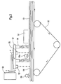
- the apparatus shown in Fig. 1 comprises a support belt 10 which is initially electrostatically charged by a corona discharge device 9.
- a radiant energy source 12 such as a computer controlled laser is used to direct de-ionizing radiation onto selected areas of the panel 11 to discharge the selected areas, thereby creating a pattern of charged and uncharged zones on the panel.
- a toner material in the form of a finely divided dry thermoplastic material is then spread on the panel 11 from a dispenser 13. Toner adheres to the remaining electrostatically charged areas of the belt, whilst loose toner is removed by a suction device 14.
- the process is then repeated with the areas which were not coated by the first toner material being recharged by a second corona discharge device 9a, and a second different toner material is spread on the panel from a dispenser 16 which adheres to these furth er charged areas. Unadhered toner is again removed by a second suction device 14a. The toners form an area 11 of deposited toner on the belt.
- the area 11 bearing the two different toners is then passed under heating apparatus 17 which fuses both tone rs.
- the first toner material provides the designed layer of the paper machine fabric, and is of a first material, whilst the second toner is of a material which can be removed later - e.g. by dissolving in water or other solvent.
- the second toner materia I is provided as a support matrix for the first toner - e.g. preventing collapse of overhangs in succeeding layers.
- the areas 11 form panels which are applied in turn to a structure such as a papermachine fabric 20 being built up on an endless conveyor 22.
- the panels 11 are released under the heating apparatus 17 after passing under guide roll 19, and the conveyor 22 is advanced by one panel length between laying down of successive panels.
- the panels 11 may be formed sepa rately from support panels, each involving a single stage process with the panels 11 being brought together between formation and depositing on the belt 22.
- the belt 10 is then passed below a cold roller 18 to return the belt 10 to its neutral temperature.
- the device shown may be one of a plurality of such devices laying panels across the width of belt 22, or may be traversed laterally across the belt to lay panels 11 side by side possibly in overlapping relationship, before the belt 22 is moved forwards by a suitable distance to allow laying of the next row of panels possibly with a degree of overlap, to promote structural integrity.
- Panels are preferably overlapped - e.g. by half a panel width/length in both the directions of movement of the belt to obtain the necessary structural integrity and strength for the finished structure.
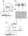
- Fig. 2 is shown diagrammatically a second embodiment of apparatus according to the invention.
- a conveyor 50 advances a fabric 51 in process of manufacture to the right, whilst each layer of the fabric is built up in turn, as the belt, which is already charged by a corona discharge device 59 is advanced by exposing each area to a first imager 52 which selectively discharges areas of the belt, then applying a first dry powder material from a dispenser 53 to the upper surface 54 of the preceding layer, to adhere to electrostatically charged areas of the surface 54 remaining after exposure to the imager 52, removing excess unadhered material, recharging the belt, using a second corona discharge device 9a, passing under a second imager 55, to discharge different areas, applying a second dry powder material from a dispenser 56, again removing excess unadhered powder, and passing the layer under a heater 57 to fuse the dry powder materials.
- the second material is removed later to leave the intended structure of the papermachine fabric 51.
- the images 52, 55 and dispensers 53, 56 are carried on a head 57 which is in turn carried on a support structure 58 which is movable no t only transversely of the conveyor 50, and in the lengthwise direction of the conveyor, but also up and down relative to the conveyor in the direction of arrows x, y and z respectively.
- These movements and the operation of the imagers are carried out under the control of a computer which may be operating a CAD program.
- Fig. 3 is a fragmentary illustration of apparatus utilizing a light projection apparatus 60 which produces the required pattern of charged and uncharged areas on a panel 61 precharged by a corona discharge device 68 by means of a mask 62 which has translucent and opaque areas to selectively expose and discharge the panels 61.
- a shutter mechanism 63 is used to regulate the length of exposure.
- a dispenser for dry powder material 64 distributes material on the exposed panel 61, and excess unadhered powder may be removed. The powder is fused by exposure to a heat source such as a heater 65, as the panels are applied to a fabric 66 as it is being built up on a conveyor 67 in a similar manner to that described in relation to Fig. 1 above.
- Fig. 4 shows a variant, where a platten 70 which carries a printed master 71 is illuminated by a lamp 72, and the reflected image is focused by a collimator lens system 73 upon a panel 74 precharged by a cor ona discharge device 9a.
- the master 71 bears a black and white printed image of the configuration of the layer, and may be provided on a paper or acetate transparency sheet.
- the panel 71 is treated in the same way as in Fig. 3, i.e. with a dry powder dispenser 76, fusing heater 77, and laid down into a fabric 78, preferably in an overlapping pattern as described in relation to Fig. 1.
- Fig. 5 shows by way of a simplest case example, a cross section through a papermachine fabric or part thereof 80, in the form of a perforated membrane or mesh comprising lands 81 and apertures 82.
- the lands are built up from a plurality of layers 83.
- Machine direction or cross -direction reinforcing yarns can be incorporated into the structure within the lands 81.
- Fig. 6 shows, again as a simplest case example, a fragment of a mask 62 (from Fig. 3) or a printed master 71 (from Fig. 4) for use in fabricating a mesh or membrane according to Fig. 5.
- This comprises lands 90 and apertures 91 (in the case of a mask) or inked areas 90 and blank spaces 91 which must be totally opaque to afford nil transmission of light in the case of a printed master.
- reinforcing yarns may be incorporated into the lands 90.
- the structur es which can be produced by the invention are potentially far more complex, and fabrics may be created which comprise several different zones with different characteristics, superposed in a unitary structure.
- the apert ures 82 may be tapered by reducing the size thereof in each succeeding layer 83.
Landscapes
- Paper (AREA)
Applications Claiming Priority (1)
| Application Number | Priority Date | Filing Date | Title |
|---|---|---|---|
| DE102004035370A DE102004035370A1 (de) | 2004-07-21 | 2004-07-21 | Herstellung einer Papiermaschinen-Bespannung |
Publications (2)
| Publication Number | Publication Date |
|---|---|
| EP1619293A2 true EP1619293A2 (de) | 2006-01-25 |
| EP1619293A3 EP1619293A3 (de) | 2006-09-20 |
Family
ID=35094361
Family Applications (1)
| Application Number | Title | Priority Date | Filing Date |
|---|---|---|---|
| EP05104982A Withdrawn EP1619293A3 (de) | 2004-07-21 | 2005-06-08 | Herstellung eines Papiermachergewebes |
Country Status (3)
| Country | Link |
|---|---|
| US (1) | US20060017196A1 (de) |
| EP (1) | EP1619293A3 (de) |
| DE (1) | DE102004035370A1 (de) |
Cited By (1)
| Publication number | Priority date | Publication date | Assignee | Title |
|---|---|---|---|---|
| CN109371735A (zh) * | 2018-11-10 | 2019-02-22 | 长沙云聚汇科技有限公司 | 一种表层抗菌无纺布加工装置 |
Family Cites Families (6)
| Publication number | Priority date | Publication date | Assignee | Title |
|---|---|---|---|---|
| US3617442A (en) * | 1968-09-30 | 1971-11-02 | Alfred A Hurschman | Paper-making means and method |
| US4541895A (en) * | 1982-10-29 | 1985-09-17 | Scapa Inc. | Papermakers fabric of nonwoven layers in a laminated construction |
| US4575330A (en) * | 1984-08-08 | 1986-03-11 | Uvp, Inc. | Apparatus for production of three-dimensional objects by stereolithography |
| US5593531A (en) * | 1994-11-09 | 1997-01-14 | Texas Instruments Incorporated | System, method and process for fabrication of 3-dimensional objects by a static electrostatic imaging and lamination device |
| US6676054B2 (en) * | 2001-03-23 | 2004-01-13 | E. I. Du Pont De Nemours And Company | Unwinder for as-spun elastomeric fiber |
| GB0227185D0 (en) * | 2002-11-21 | 2002-12-24 | Voith Fabrics Heidenheim Gmbh | Nonwoven fabric |
-
2004
- 2004-07-21 DE DE102004035370A patent/DE102004035370A1/de not_active Withdrawn
-
2005
- 2005-06-08 EP EP05104982A patent/EP1619293A3/de not_active Withdrawn
- 2005-07-20 US US11/184,902 patent/US20060017196A1/en not_active Abandoned
Cited By (1)
| Publication number | Priority date | Publication date | Assignee | Title |
|---|---|---|---|---|
| CN109371735A (zh) * | 2018-11-10 | 2019-02-22 | 长沙云聚汇科技有限公司 | 一种表层抗菌无纺布加工装置 |
Also Published As
| Publication number | Publication date |
|---|---|
| US20060017196A1 (en) | 2006-01-26 |
| EP1619293A3 (de) | 2006-09-20 |
| DE102004035370A1 (de) | 2006-03-16 |
Similar Documents
| Publication | Publication Date | Title |
|---|---|---|
| EP1619302A1 (de) | Herstellung von Papiermaschinenbespannungen | |
| US12350878B2 (en) | Manufacturing process for papermaking belts using 3D printing technology | |
| EP1567322B1 (de) | Dreidimensionaler tomographischer mehrschichtstoff | |
| CN100532708C (zh) | 制造干燥织物的方法及具有背面排气性以获得提高的纸幅稳定性的干燥织物 | |
| KR101212301B1 (ko) | 제지기 직물 및 산업 직물의 구조 요소를 서로 결합시키는방법 및 그에 의해 제조된 직물 | |
| MXPA05007186A (es) | Metodo para fabricar una banda y la banda utilizada para hacer panuelos de papel y toallas con volumen y articulos y telas no tejidos. | |
| MXPA05005835A (es) | Telas no tejidas de secado a traves de aire y de transferencia para hacer tisu. | |
| KR20050091044A (ko) | 산업 직물에의 고분자의 선택적 퇴적의 제어 방법 및 그산업 직물 | |
| JP4768268B2 (ja) | 製紙と紙加工に関する応用のための樹脂含浸エンドレスベルト構造を製造するための方法及びそのベルト | |
| EP0342171B1 (de) | Verfahren zum Anbringen von Teilchen und eines Bindemittels aus einem Grundgewebe | |
| RU2394119C2 (ru) | Полупроницаемые ткани для транспортных лент и прессовых тканей | |
| EP1685294A2 (de) | Dreidimensionaler tomographischer gewebeaufbau | |
| JP2003313792A (ja) | 抄紙機用布およびその製造方法 | |
| CN100532707C (zh) | 树脂浸渍环状带的制造方法及用于造纸机和类似产业应用的带 | |
| US20060127641A1 (en) | Papermachine clothing having reduced void spaces | |
| US11571866B2 (en) | Manufacturing process for papermaking endless belts using 3D printing technology | |
| EP1619293A2 (de) | Herstellung eines Papiermachergewebes | |
| US7332451B2 (en) | Papermachine clothing having reduced void spaces | |
| US20060070217A1 (en) | Hydroentanglement screen | |
| US20020052160A1 (en) | Fluid-pervious fabric and a method of producing it | |
| EP1201400A1 (de) | Flüssigkeitsdurchlässiges Gewebe und Verfahren zu dessen Herstellung | |
| EP1629953A1 (de) | Verfahren zur Herstellung von bahnförmigen Gebilden |
Legal Events
| Date | Code | Title | Description |
|---|---|---|---|
| PUAI | Public reference made under article 153(3) epc to a published international application that has entered the european phase |
Free format text: ORIGINAL CODE: 0009012 |
|
| AK | Designated contracting states |
Kind code of ref document: A2 Designated state(s): AT BE BG CH CY CZ DE DK EE ES FI FR GB GR HU IE IS IT LI LT LU MC NL PL PT RO SE SI SK TR |
|
| AX | Request for extension of the european patent |
Extension state: AL BA HR LV MK YU |
|
| PUAL | Search report despatched |
Free format text: ORIGINAL CODE: 0009013 |
|
| AK | Designated contracting states |
Kind code of ref document: A3 Designated state(s): AT BE BG CH CY CZ DE DK EE ES FI FR GB GR HU IE IS IT LI LT LU MC NL PL PT RO SE SI SK TR |
|
| AX | Request for extension of the european patent |
Extension state: AL BA HR LV MK YU |
|
| RAP1 | Party data changed (applicant data changed or rights of an application transferred) |
Owner name: VOITH PATENT GMBH |
|
| 17P | Request for examination filed |
Effective date: 20070320 |
|
| AKX | Designation fees paid |
Designated state(s): AT BE BG CH CY CZ DE DK EE ES FI FR GB GR HU IE IS IT LI LT LU MC NL PL PT RO SE SI SK TR |
|
| 17Q | First examination report despatched |
Effective date: 20071221 |
|
| STAA | Information on the status of an ep patent application or granted ep patent |
Free format text: STATUS: THE APPLICATION IS DEEMED TO BE WITHDRAWN |
|
| 18D | Application deemed to be withdrawn |
Effective date: 20080702 |