EP1567322B1 - Dreidimensionaler tomographischer mehrschichtstoff - Google Patents
Dreidimensionaler tomographischer mehrschichtstoff Download PDFInfo
- Publication number
- EP1567322B1 EP1567322B1 EP03767669A EP03767669A EP1567322B1 EP 1567322 B1 EP1567322 B1 EP 1567322B1 EP 03767669 A EP03767669 A EP 03767669A EP 03767669 A EP03767669 A EP 03767669A EP 1567322 B1 EP1567322 B1 EP 1567322B1
- Authority
- EP
- European Patent Office
- Prior art keywords
- fabric
- nozzle
- temporary support
- layer
- nozzles
- Prior art date
- Legal status (The legal status is an assumption and is not a legal conclusion. Google has not performed a legal analysis and makes no representation as to the accuracy of the status listed.)
- Expired - Lifetime
Links
Images


Classifications
-
- D—TEXTILES; PAPER
- D21—PAPER-MAKING; PRODUCTION OF CELLULOSE
- D21F—PAPER-MAKING MACHINES; METHODS OF PRODUCING PAPER THEREON
- D21F7/00—Other details of machines for making continuous webs of paper
- D21F7/08—Felts
- D21F7/083—Multi-layer felts
-
- B—PERFORMING OPERATIONS; TRANSPORTING
- B29—WORKING OF PLASTICS; WORKING OF SUBSTANCES IN A PLASTIC STATE IN GENERAL
- B29C—SHAPING OR JOINING OF PLASTICS; SHAPING OF MATERIAL IN A PLASTIC STATE, NOT OTHERWISE PROVIDED FOR; AFTER-TREATMENT OF THE SHAPED PRODUCTS, e.g. REPAIRING
- B29C64/00—Additive manufacturing, i.e. manufacturing of three-dimensional [3D] objects by additive deposition, additive agglomeration or additive layering, e.g. by 3D printing, stereolithography or selective laser sintering
- B29C64/10—Processes of additive manufacturing
- B29C64/106—Processes of additive manufacturing using only liquids or viscous materials, e.g. depositing a continuous bead of viscous material
- B29C64/112—Processes of additive manufacturing using only liquids or viscous materials, e.g. depositing a continuous bead of viscous material using individual droplets, e.g. from jetting heads
-
- B—PERFORMING OPERATIONS; TRANSPORTING
- B29—WORKING OF PLASTICS; WORKING OF SUBSTANCES IN A PLASTIC STATE IN GENERAL
- B29C—SHAPING OR JOINING OF PLASTICS; SHAPING OF MATERIAL IN A PLASTIC STATE, NOT OTHERWISE PROVIDED FOR; AFTER-TREATMENT OF THE SHAPED PRODUCTS, e.g. REPAIRING
- B29C64/00—Additive manufacturing, i.e. manufacturing of three-dimensional [3D] objects by additive deposition, additive agglomeration or additive layering, e.g. by 3D printing, stereolithography or selective laser sintering
- B29C64/40—Structures for supporting 3D objects during manufacture and intended to be sacrificed after completion thereof
-
- B—PERFORMING OPERATIONS; TRANSPORTING
- B33—ADDITIVE MANUFACTURING TECHNOLOGY
- B33Y—ADDITIVE MANUFACTURING, i.e. MANUFACTURING OF THREE-DIMENSIONAL [3D] OBJECTS BY ADDITIVE DEPOSITION, ADDITIVE AGGLOMERATION OR ADDITIVE LAYERING, e.g. BY 3D PRINTING, STEREOLITHOGRAPHY OR SELECTIVE LASER SINTERING
- B33Y40/00—Auxiliary operations or equipment, e.g. for material handling
-
- B—PERFORMING OPERATIONS; TRANSPORTING
- B33—ADDITIVE MANUFACTURING TECHNOLOGY
- B33Y—ADDITIVE MANUFACTURING, i.e. MANUFACTURING OF THREE-DIMENSIONAL [3D] OBJECTS BY ADDITIVE DEPOSITION, ADDITIVE AGGLOMERATION OR ADDITIVE LAYERING, e.g. BY 3D PRINTING, STEREOLITHOGRAPHY OR SELECTIVE LASER SINTERING
- B33Y70/00—Materials specially adapted for additive manufacturing
-
- D—TEXTILES; PAPER
- D04—BRAIDING; LACE-MAKING; KNITTING; TRIMMINGS; NON-WOVEN FABRICS
- D04H—MAKING TEXTILE FABRICS, e.g. FROM FIBRES OR FILAMENTARY MATERIAL; FABRICS MADE BY SUCH PROCESSES OR APPARATUS, e.g. FELTS, NON-WOVEN FABRICS; COTTON-WOOL; WADDING ; NON-WOVEN FABRICS FROM STAPLE FIBRES, FILAMENTS OR YARNS, BONDED WITH AT LEAST ONE WEB-LIKE MATERIAL DURING THEIR CONSOLIDATION
- D04H3/00—Non-woven fabrics formed wholly or mainly of yarns or like filamentary material of substantial length
- D04H3/02—Non-woven fabrics formed wholly or mainly of yarns or like filamentary material of substantial length characterised by the method of forming fleeces or layers, e.g. reorientation of yarns or filaments
-
- D—TEXTILES; PAPER
- D04—BRAIDING; LACE-MAKING; KNITTING; TRIMMINGS; NON-WOVEN FABRICS
- D04H—MAKING TEXTILE FABRICS, e.g. FROM FIBRES OR FILAMENTARY MATERIAL; FABRICS MADE BY SUCH PROCESSES OR APPARATUS, e.g. FELTS, NON-WOVEN FABRICS; COTTON-WOOL; WADDING ; NON-WOVEN FABRICS FROM STAPLE FIBRES, FILAMENTS OR YARNS, BONDED WITH AT LEAST ONE WEB-LIKE MATERIAL DURING THEIR CONSOLIDATION
- D04H3/00—Non-woven fabrics formed wholly or mainly of yarns or like filamentary material of substantial length
- D04H3/08—Non-woven fabrics formed wholly or mainly of yarns or like filamentary material of substantial length characterised by the method of strengthening or consolidating
- D04H3/10—Non-woven fabrics formed wholly or mainly of yarns or like filamentary material of substantial length characterised by the method of strengthening or consolidating with bonds between yarns or filaments made mechanically
- D04H3/11—Non-woven fabrics formed wholly or mainly of yarns or like filamentary material of substantial length characterised by the method of strengthening or consolidating with bonds between yarns or filaments made mechanically by fluid jet
-
- D—TEXTILES; PAPER
- D21—PAPER-MAKING; PRODUCTION OF CELLULOSE
- D21F—PAPER-MAKING MACHINES; METHODS OF PRODUCING PAPER THEREON
- D21F1/00—Wet end of machines for making continuous webs of paper
- D21F1/0027—Screen-cloths
-
- D—TEXTILES; PAPER
- D21—PAPER-MAKING; PRODUCTION OF CELLULOSE
- D21F—PAPER-MAKING MACHINES; METHODS OF PRODUCING PAPER THEREON
- D21F1/00—Wet end of machines for making continuous webs of paper
- D21F1/0027—Screen-cloths
- D21F1/0081—Screen-cloths with single endless strands travelling in generally parallel convolutions
-
- B—PERFORMING OPERATIONS; TRANSPORTING
- B33—ADDITIVE MANUFACTURING TECHNOLOGY
- B33Y—ADDITIVE MANUFACTURING, i.e. MANUFACTURING OF THREE-DIMENSIONAL [3D] OBJECTS BY ADDITIVE DEPOSITION, ADDITIVE AGGLOMERATION OR ADDITIVE LAYERING, e.g. BY 3D PRINTING, STEREOLITHOGRAPHY OR SELECTIVE LASER SINTERING
- B33Y80/00—Products made by additive manufacturing
Definitions
- This invention relates to industrial nonwoven fabrics and has particular, though not exclusive, relevance to nonwoven papermachine fabrics such as forming fabrics, press felts, dryer fabrics, through-air dryer (TAD) fabrics, hydroentanglement screens and transfer fabrics for use in a papermachine.
- the fabrics of the invention also have application as transfer/conveyor fabrics in machines other than papermachines and may be used, for example, as conveying fabrics, or as screens for latex impregnation of conventionally air-laid materials, and for support or formation screens used in melt blowing or spun bonded nonwoven fabric manufacture.
- Paper is conventionally manufactured by conveying a paper furnish, usually consisting of an initial slurry of cellulosic fibres, on a forming fabric or between two forming fabrics in a forming section, the nascent sheet then being passed through a pressing section and ultimately through a drying section of a papermaking machine.
- a paper furnish usually consisting of an initial slurry of cellulosic fibres
- the paper web is transferred from the press fabric to a Yankee dryer cylinder and then creped, or alternatively on more modem machines a monofilament woven mesh dryer fabric conveys the web from the forming fabric to a through-air dryer, followed by a Yankee cylinder.
- Papermachine clothing is essentially employed to carry the paper web through these various stages of the papermaking machine and to facilitate water removal from the sheet in a controlled manner.
- the fibrous furnish is wet-laid onto a moving forming wire and water is encouraged to drain from it by means of suction boxes and foils.
- the paper web is then transferred to a press fabric that conveys it through the pressing section, where it is usually passes through a series of pressure nips formed by rotating cylindrical press rolls or cylindrical press rolls and shoe press belts. Water is squeezed from the paper web and into the press fabric as the web and fabric pass through the nip together.
- the paper web is transferred either to a Yankee dryer, in the case of tissue paper manufacture, or to a set of dryer cylinders upon which, aided by the clamping action of the dryer fabric, the majority of the remaining water is evaporated.
- Papermachine fabrics traditionally consist of a woven fabric. As the warp and weft yarns interweave, a so-called "knuckles" is formed as they cross. These knuckles have a tendency to mark the paper sheet formed on the fabric. This problem is particularly apparent at the wet end of the papermachine where the sheet is still highly plastic. In recent years, various methods have been suggested for making nonwoven papermachine fabrics in order to eradicate the problem associated with knuckle marking, particularly for press and dryer section applications. Many of these have been impractical to manufacture commercially.
- US 3,617,442 describes a forming fabric comprising a sheet of synthetic, open-celled, flexible foam such as polyurethane. This is reinforced by a series of polyester cables, a coarse wire screen or a thin flexible metal or plastic sheet. Such an arrangement, if ever commercialised, would exhibit poor wear resistance.
- GB 2,051,154 relates to a so-called "link belt” in which a base fabric is formed from a series of interdigitated helices joined together by pintle wires.
- Link belts are only suitable for certain applications, due to calliper and material restrictions.
- US 4,541,895 describes a papermakers' fabric made up of a plurality of nonwoven sheets laminated together to define a fabric or belt.
- the nonwoven sheets are perforated by laser drilling.
- Such sheets are composed of unoriented polymer material, and if produced in the fineness needed for papermaking applications, would lack sufficient dimensional stability to operate as endless belts on papermachines.
- the subject invention of GB 2,235,705 describes a base fabric for press felts.
- an array of sheath core yarns of which the core has a higher melting point than the sheath is fed in spaced parallel disposition to peripheral grooves of a pressed roller arranged in nip-forming relationship with a press roll.
- the material of the sheath is melted as the yarns move into and through the roller nip and excess melted sheath material is forced into lateral and vacant circumferential grooves in the roller to form structural members between adjacent yarns.
- a wide belt may be formed by joining similar strips together.
- a batt of fibres is subsequently needled to the base fabric so as to form a press felt.
- the base fabric provided in accordance with GB 2,235,705 has large land areas.
- GB 2,241,915 relates to a method of producing a papermaking fabric in which a layer of photopolymeric resin is applied to a moving band.
- a moving, selectively transparent, mask is positioned above the resin and the resin is irradiated through the mask to effect an at least partial cure of the parts of the resin layer in register with the transparent regions or the mask.
- uncured regions of the resin are removed by pressure fluid jets and final curing of the resin is effected either thermally or by means of flooding actinic radiation.
- the foraminous sheet so formed may be reinforced with yarns or fibres. Once again holes extend straight through the fabric. This is undesirable for paper sheet formation and additionally permits the occurrence of harmful "backwash" which comes from hydraulic pulses passing through the fabric from the machine side. The direct passage of these pulses disturbs the fragile cellulosic fibrous network.
- GB 2,283,991 relates to papermachine clothing made from partially fused particles. A reinforcing structure is embedded within the structure. This papermachine clothing is suitable for pressing applications and possibly special forming applications.
- US-A-5,936,861 describes a process and apparatus for making three-dimensional, composite material objects of a predetermined shape by sequentially depositing multiple layers of continuous reinforcement fibers and solidifying matrix material on a base member in a desired pattern.
- the apparatus comprises a movable nozzle having a flow passage and a dispensing outlet, a supply of reinforcement fibers and a matrix material, a mixing device for impregnating the fibers with a matrix material to form a preimpregnated tow, and a heating device for introducing the matrix material in a fluid state, a base member to support the object being made, mechanical movement devices for moving the base member relative to the movable nozzle in a predetermined sequence and pattern, and for displacing the movable nozzle a predetermined incremental distance relative to the base member and relative to each successive layer deposited prior to the start of the formation of each successive layer to form multiple layers of composite material of a predetermined thickness, and a metering device for discharging the preimpregnated tow at
- the apparatus preferably further comprises a computer-aided design computer and supporting software programs that are capable of creating a three-dimensional drawing of a desired object and converting the drawing into multiple elevation layer data, and a three-dimensional motion controller electronically linked to the mechanical movement devices and operative to actuate these movement devices in response to the drive signals received from the computer.
- US 5,501,824 describes an apparatus and method of making three-dimensional objects out of a modified wax, which becomes fluid on heating.
- the solid wax object may easily be damaged.
- the method would have particular application in the production of small prototypes, which are then generally embedded in foundry moulding sand to enable a metal casting to be made.
- the prototypes are formed, on a vertically moveable platform, by disposing the material in a controlled manner from a nozzle.
- the nozzle and platform are moveable under the control of a computer such that the material dispensed from the nozzle is in the correct location to build up the prototype in the manner illustrated in a CAD system connected to the computer.
- Support material for the desired object is constructed first during the method, where required, and is later removed.
- US 5,121,329 discloses a method of making a 3D object by what is now called Fused Deposition Modelling.
- FFF Free Form Fabrication
- Free Form Fabrication as used herein embraces so-called selective deposition modelling and so-called fused deposition modelling.
- An example of selective deposition modelling is found in US 5,501,824 .
- An example of fused deposition modelling is found in US 5,121,329 .
- the fabrics in accordance with the invention have particular, although not exclusive, application in the manufacture of papermachine clothing. This technology has been identified as being ideally suitable for the manufacture of forming fabrics, base fabrics for press felts and dryer fabrics.
- Free Form Fabrication describes the formation of a three-dimensional object, tomographically layer by layer, in a stepwise fashion out of a material capable of physical transformation. This may be achieved in a number of ways.
- SDM selective deposition modelling
- FDM fused deposition modelling
- a monofilament feed yarn is melted, and then extruded, via a micro-extruder, in fine filament form via a head which can move in x, y and z directions, i.e. vertically and horizontally in two planes.
- layers of fluid material are laid down stepwise in the desired locations and are each solidified as they are laid down.
- a method of making a fabric from a material comprising the following steps:- feeding material from at least one nozzle onto a moveable belt, wherein said nozzle is moveable for translational movement and the spacing between said nozzle and the belt is adjustable, and wherein flow through said nozzle and translational movement of said nozzle is controlled such that said nozzle dispenses the material in a controlled manner to form the fabric layer-by-layer.
- the nozzles are ideally provided in at least one feed head so as to provide a "multi-jet" arrangement, a number of nozzles being provided in each feed head.
- a plurality of feed heads would conventionally be used with selective deposition modelling.
- the flow through the nozzle is quantised; i.e. droplets are projected rather than there being a continuous stream of fluid,
- the nozzles together might typically be dispensing about 12,000 drops (pico litre size), per second.
- fused deposition modelling one nozzle is generally provided for each micro-extruder head. The material is extruded from the nozzles.
- the method of the invention facilitates the manufacture of a wide variety of fabric configurations.
- a wide variety of foraminous fabrics may be made having any aperture size, shape and distribution.
- the aperture size, shape and/or distribution may be deliberately varied, within desirable tolerances, throughout (or at least in the paper support surface of) the fabric although the porosity of the fabric should be kept as uniform as possible.
- the fabrics of the invention ideally comprise an array of yarns extending in the intended running direction thereof, on a machine. Consequently drawn yarns, to prevent extension, are preferably added to the built up fabric. These yarns provide strength in the machine direction.
- the yarns are preferably monofilaments or multifilaments and are ideally made from any of the following materials: steel, polyester, polyamide, polyolefin, PPS, PEEK, para- aramid or from inorganic material, for example glass or basalt.
- the yarns are preferably at least partly, and ideally fully, encapsulated in the machine direction lands of the nonwoven fabric as built up in the method of the invention.
- the aforesaid material for making the fabric is normally (at room temperature (20°C)) in a solid state and preferably is made molten by heating. In such circumstances the droplets of material cool and thus solidify as they are deposited.
- a preferred material for making the fabric, by selective deposition modelling comprises a low viscosity (2-200 Centipoise, more preferably 5-40 Centipoise, measured at room temperature (20 °C)) meltable polymeric material.
- the apparatus for use in the method of the invention may be In Vision Si2 of 3D Systems, which is for use in the manufacture of items by selective deposition modelling using electrically activated piezo crystals.
- two polymers are projected out of different nozzles of the same feed head.
- One polymer is the true building material and the other is a support or scaffolding material, which may comprise, for example, a modified wax.
- the latter material provides temporary support for subsequent layers of building material which may later be removed thermally, possibly by the application of hot water.
- a preferred material for making the fabric by selective deposition modelling would comprise a meltable polymer which solidifies on cooling. Such polymers are often referred to as "phase change materials".
- Suitable thermoplastic materials for the construction of the fabric by selective deposition modelling include, but are not limited to, any of the following either alone or in combination:- polyamides, co-polyamides, polyesters, co-polyesters, amide esters, olefin resins, urethanes, amide urethanes and sulphones.
- An alternative preferred material for making the fabric by selective deposition modelling comprises a curable material, such as a radiation curable material.
- a curable material such as a radiation curable material.
- a UV curable resin may be used, such as an acrylate-based UV curable resin, which material solidifies on exposure to UV light.
- the curable material may be delivered to the apparatus in the form of a relatively viscous gel which may be heated to lower its viscosity to a suitable level to enable droplets thereof to be formed for projection out of the nozzles, which in the case of the In Vision Si2 apparatus comprise piezo crystal controlled nozzles.
- Suitable monomers or oligomers which solidify under the influence of UV light of suitable wavelength, include, but are not limited to, any of the following, either alone or in combination: epoxy acrylates, polyester acrylates, silicone acrylates and urethane acrylates. Cross-linking of such materials may be promoted using a compatible photo initiator. The rate of cross-linking may, if desired, be increased using a synergist, such as an acrylated amine.
- Heating of the UV curable resins may not in every case be necessary for effective production of the fabric by selective deposition modelling. However, it may nevertheless be desirable that the UV curable resin be heated in order to optimise the viscosity of the resin for projection through the nozzles of the apparatus.
- these comprise hot melt resins or waxes, said materials having melting points lower than the polymer(s) comprising the true building, or matrix, material.
- the true building, or matrix material is preferably supplied to the dispensing head in the form of a flexible strand of solid material from a supply source, such as a reel or rod.
- a supply source such as a reel or rod.
- This material is heated above its solidification temperature (Tm) by a heater and then dispensed by extrusion and applied as a fluid.
- Tm solidification temperature
- thermoplastic materials for use in making the fabric by fused deposition modelling include, but are not limited to, any of the following either alone or in combination:- polyesters, polyamides, high molecular weight polyethylenes, polyphenylene sulphide, thermoplastic polyurethanes and PEEK.
- the resin for forming the fabric may be supplemented with a second resin or other material, which acts as a support structure for the manufacture of the fabric.
- This second resin or other material is ideally dissolvable or removable thermally at a temperature that does not affect the stability of the fabric.
- Suitable examples of such materials include any of the following either alone or in combination:- PEO (poly(2-ethyl-2-oxazoline)), polyvinyl alcohol, polyethylene oxide, methyl vinyl ether, polyvinyl pyrrolidone-based polymers, maleic acid-based polymers and alkali-soluble base polymers containing carboxylic acid and plasticiser.
- the fabric filaments embodied in the structure, which are built up during the process may be of any cross-section, e.g. round, square or triangular.
- the method of the invention may be used to form complicated fabric structures, with filaments of end sections, which cannot be utilised in conventional weaving.
- the fabric may comprise lands, filaments or strands which are triangular in cross-section. Yarns with such end sections would be liable to twisting or distortion during insertion into a woven fabric on a loom.
- apertures are provided in the support surface having dimensions which would accord to those of current woven fabrics.
- fabrics having smaller apertures may be made in accordance with the method of the invention.
- the notional diameter of the apertures would be in the range from 100 ⁇ m to 800 ⁇ m.
- an apparatus 10 for making a nonwoven forming fabric, without the disadvantage of knuckles formed by yarn interlacings, by SDM in accordance with the present invention comprises a plurality of feed heads 13 mounted in such a manner as to facilitate translational movement in both the X and Y directions as well as vertically in the Z direction.
- each feed head 13 typically comprises about 450 dispensing nozzles (not shown), although more may be used.
- the feed heads In the Y direction the feed heads must be capable of sufficient travel such that material for making the fabric may be deposited from at least one of the nozzles of a feed head at any position in the Y-axis between the edges of the fabric being manufactured on the belt.
- the limitation of travel of adjacent feed heads 13 is such that the areas over which adjacent feed heads 13 may pass overlap. Vertical movement in the Z-direction of up to about 5mm is required to allow for continued precision of droplet deposition as the thickness of the product being made gradually increases.
- Each feed head 13 is connected via a first flexible pipe 15 to a reservoir (not shown) of heated fluid polymeric material that is normally solid in ambient conditions and which melts when sufficiently heated.
- the first flexible pipe branches off to finer tubes each of which is coupled to an individual feed head.
- heated fluid polymeric material is fed via individual channels to individual nozzles.
- the viscosity of the molten material is preferably in the range from 2-200 Centipoise, more preferably 5-40 Centipoise, measured at room temperature (20° C).
- An ionic resin may be used, such as SURLYN (Trade Mark) as marketed by Du Pont.
- the section or panel of nonwoven fabric being reproduced is formed on an endless belt 14 tensioned between two rollers.
- the belt would, generally speaking, comprise a fabric, optionally coated with a non-stick coating such as PTFE.
- manufactured material would be fed from the endless belt 14 to a storage roll.
- an endless product may be manufactured around the circumference of the belt 14.
- a representation of the panel is provided on the CAD system.
- the control computer effectively slices the CAD representation into a plurality of virtual layer representations, which are together known as a building representation.
- the control computer uses the data on the CAD system to reproduce stepwise layer by layer of the panel of the nonwoven fabric on the belt 14 by appropriate application of the molten polymeric material. As drops of polymeric material are deposited onto the belt, or as the process progresses, onto previously solidified material, there is a rapid heat loss and the drops solidify.
- Accurate location and flow of the polymeric material is achieved by a combination of controlling flow of the polymer through the nozzles 13 and the precise ejection of droplets by controlled firing of the piezo electric crystals within the feed head as well as, movement of the feed head 13 in the X, Y and Z directions.
- the method used is much the same as that described in US 5501824 , except in that a moveable belt 14 is used in place of a platform.
- strength-providing yarns are generally included in the fabric.
- the belt will then advance in a controlled manner to the position to which additional material is to be added to form the next panel or panels.
- any hollow areas in that layer may be filled in any hollow areas in that layer with a second material in order to provide support to the next layer.
- This second material can be removed once manufacture is complete, for example by washing or melting when the second material has a lower melting point than the material from which the fabric is made.
- certain nozzles of the dispensing heads would be connected via a second flexible pipe to a reservoir of such material and not to the fabric-forming material.
- a nonwoven fabric 20 in accordance with the invention, is illustrated.
- This comprises a fine planar upper grid 21 secured to the tips of a series of parallel cross-machine direction lands 22, which, in this embodiment, are triangular in section.
- the flat bases of these triangular lands 22 are secured to an array of parallel machine direction lands 23 which are square in cross section.
- the width of the paper contacting lands in the grid 21 is typically in the order of 0.1mm.
- the depth of this layer is typically about 0.1-0.2mm.
- the dimensions of the apertures defined by the lands are preferably at least 100 microns by 100 microns, though the hole shapes need not be rectangular.
- the position of the CMD lands 22 relative to the paper formation grid 21 may be varied.
- two triangular lands 22 might cover or straddle the holes.
- Many variations are possible in the interests of providing optimum dewatering efficiency and performance.
- Videomicroscope at magnification of 55X shows that hemispheres of polymer; i.e. micro-globules are produced on the surface of the lands in that the lands are built up from globules of polymer. These micro-globules help provide for good sheet release without resulting in marking of the paper formed on the surface of the structure.
- non-planar support surface at a macroscopic level. For example, this may be useful in providing sheet release with difficult pulp mixtures.
- Such a surface could be conferred upon the fabric by means of a non-planar receiving belt. This could be used to provide an, at least partially, undulating fabric surface of the type described in US 5,847,102 .
- a monofilament yarn 24 of maximum diameter 0.2mm is encapsulated in each of the machine direction lands 23 below the fabric supporting grid 21 so as to provide strength in the running direction of the fabrics when in use.
- This maximum diameter may be appropriate for forming fabrics. For other fabrics other diameters might be appropriate. For example, for dryer fabrics a maximum diameter of 0.6mm may be appropriate.
- These monofilament yarns could be pre-assembled in spiral fashion during manufacture. The laying down of polymeric material would take account of the very slight sideways movement of the yarns. An electronic follower could be used to establish an exact reference point before the onset of printing each panel.
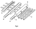
- Fig. 4 the sequence of fabric build (a) to (c), at the roll side of the fabric, shows how a semi-circle is created to allow yarn to be introduced at (a). Thereafter in (b) and then (c) the jet printing of material builds up around the yarn to eventually fully encapsulate it.
- the strength providing yarns in the machine direction need not be monofilaments.
- fine multifilament yarns could be used (e.g. dtex 500).
- the yarns may, for example, be made of steel, polyester, polyamide, polyolefin, PPS, PEEK, para-aramid or from inorganic material, e.g. glass or basalt. Bonding to the polymeric surface may be enhanced by suitable surface treatments such as tie-coats or surface activation such as plasma treatment.
- a nonwoven fabric of the invention may be secured on its underside, to a conventional fabric such as a woven fabric or possibly to a further nonwoven fabric or knitted fabric.
- the fabric of the invention can also be secured at its topside to a fine woven forming fabric to yield specific formation properties as desired or to nonwoven fibrous batts.
- the fabric would preferably be built up in endless form to avoid seaming problems as are commonly encountered in the art when making seamed belts, particularly for use in papermaking. Such problems are more apparent for belts used at the wet end of the papermachine; i.e. forming fabrics.
- differential permeability between the seam and the rest of the belt can cause unacceptable marking of the paper sheet as formed in the seam area of the belt. Considerable time and effort and thus cost are involved in attempting to minimise these problems.
- the fabric has particular application as a forming fabric in that it provides a fine support network for the paper furnish whilst at the same time allowing for controlled drainage, as aided by the orientation, number and cross-section of the created "yarns" or filaments within the fabric.
- the adoption of at least some filaments that are triangular (including substantially triangular), or other yarns having a good hydrodynamic shape, is valuable in this respect.
- the invention proposes to build up the fabric from a number of filaments extending in both the machine direction and cross machine direction. This is achieved using an array of multi-jet heads, which effectively print a series of panels in a row, ideally in the cross-machine direction. This is illustrated in Fig. 5 .
- the heads are programmed by the computer to print panels 25 with multiple tongue and groove combinations, alternative arrangements being shown in Figs. 5a and 5b .
- some tongues are chosen to be longer than others to enhance panel bonding.
- the panels are made up stepwise by a series of layers Z 1 -Z 5 .
- the growth of the fabric in the machine direction is achieved by forming a panel, or in the case of a multi-head manufacturing assembly a series of panels, onto the moveable belt 14.
- the support belt for the growing foraminous polymer assembly could possibly advance continuously but slowly forwards, but generally speaking and preferably, the belt would be arrested in a static state whilst a full panel consisting of discrete layers Z 1 - Z 4 is built up.
- This intermittent movement of the belt provides for more accurate delivery of the polymeric material.
- Another benefit is that maintenance of the polymer feed heads can take place whilst the belt is in a static state without detriment to any partially manufactured belt on the machine.
- the complete panel 25 (i) has been constructed the belt then advances for the commencement of the following panel 25 (ii). This process is repeated until the complete belt has been manufactured in both length and width directions.
- a further embodiment 35 of the nonwoven fabric of the invention is illustrated.
- the triangular end section intermediate layer has been replaced with angled ribs 36. This may serve to better control drainage.
- a sheet 37 comprising an array of perforations of random size and shape is used to support the paper web, although the overall integrated (or average) pore size over a given area ideally remains uniform.
- the fabric of Fig. 9 is made in a like manner to the other fabrics of the invention as previously described. It is relatively straightforward to build up a fabric in which a support sheet layer having a random distribution of holes is integral with regularly spaced lands located therebelow. A temporary lay down phase of wax or the like is used to fill the gaps between the lands below the intended location of the sheet and the sheet is built up over the lands and temporary filler material. This temporary material is removed, for example by washing or melting, after fabric manufacture is complete.
- Fig. 10 The embodiment of Fig. 10 is similar to that shown in Fig. 9 except that the cross-machine direction triangular lands 38 are curved so as to prevent them from encroaching upon the perforations in the paper pulp support layer 39 which is similar to that described with reference to Fig. 9 .
- a further apparatus 40 for making a nonwoven dryer fabric in accordance with the present invention comprises a plurality of feed heads 41 mounted in such a manner as to facilitate translational movement in both the X and Y directions as well as vertically in the Z direction.
- the apparatus 40 is similar to that disclosed in relation to Fig. 1 except that this apparatus is designed to manufacture a fabric by fused deposition modelling.
- each feed head 41 comprises two sets of dispensing nozzles, one of which receives PPS plastics filament of about 1 /16 inch diameter from a feed reel.
- plastics pellets might be fed from a hopper rather than a filament.
- the other set of dispensing nozzles is fed a filament of a second, preferably water soluble acrylic polymer, material from a second feed reel. Again, alternatively this material may be supplied via a hopper.
- the first plastic filament is used to manufacture the fabric, whereas the second filament is used to form the "temporary lay down phase" as discussed with reference to Fig. 1 .
- the plastic filaments are fed to the extrusion nozzles where they are heated so as to melt and thus fluidise the plastic. Extruded flow through each nozzle is controlled by a valve mechanism at the nozzle. The emerging extrudate is continuous until flow is terminated via the valve to allow the feed head to jump a deposition gap before the flow is reinstated.
- Each feed head comprises two dispensing nozzles, although more may be used.
- the FDM apparatus would comprise 4 to 40, and more preferably 10 to 30, feed heads.
- the nozzles are movable in the X, Y and Z directions.
- the feed heads In the Y direction the feed heads must be capable of sufficient travel such that material for making the fabric may be extruded from at least one of the nozzles of a feed head at any position in the Y-axis between the edges of the fabric being manufactured on the belt.
- the limitation of travel of adjacent feed heads is such that the areas over which adjacent nozzles may pass overlap. Vertical movement in the Z-direction of up to about 5mm is required to allow for continued precision of deposition of extruded material as the thickness of the product being made gradually increases.
- the section or panel of nonwoven fabric being reproduced is formed on an endless belt 42 tensioned between two rollers.
- the belt 42 would, generally speaking, comprise a fabric, optionally coated with a non-stick coating such as PTFE.
- a representation of the panel is provided on the CAD system.
- the control computer effectively slices the CAD representation into a plurality of virtual layer representations, which are together known as a building representation.
- the control computer uses the data on the CAD system to reproduce stepwise layer by layer of the panel of the nonwoven fabric on the belt 42 by appropriate application of a thin bead of extruded molten polymeric material to form each layer.
- a thin bead of extruded molten polymeric material to form each layer.
- Accurate location and flow of the polymeric material is achieved by a combination of controlling flow of the polymer through the nozzles in the feed head 41 via valves and movement of the feed head 41 in the X, Y and Z directions.
- the method used is much the same as that described in US 5,121,329 , except in that a movable belt 42 is used in place of a platform.
- strength-providing yarns are generally included in the intended machine direction of the fabric.
- the belt will then advance in a controlled manner to the position to which additional material is to be added to form the next panel or panels.
- any hollow areas in that layer may be filled in any hollow areas in that layer with a second material in order to provide support to the next layer.
- This second material can be removed once manufacture is complete, for example by dissolving, washing or melting when the second material has a lower melting point than the material from which the fabric is made.
- certain nozzles of the dispensing heads would be connected via a second flexible pipe to a reservoir of such material and not to the fabric-forming material.
- the entire system is ideally contained within a heated enclosure, which is held at a temperature just less than the melting point of the plastics being extruded. Thus only a small amount of energy needs to be supplied by the extrusion nozzle to cause the plastics to melt.
- the method of manufacture using fused deposition modelling and the apparatus shown in Fig. 11 may be used to manufacture any of the structures made in accordance with the apparatus of Fig. 1 and illustrated in Figs. 2 to 4 and 7 to 10. Likewise the apparatus may be used to manufacture panels as shown in Figs. 5 and 6 .
Landscapes
- Engineering & Computer Science (AREA)
- Chemical & Material Sciences (AREA)
- Materials Engineering (AREA)
- Manufacturing & Machinery (AREA)
- Mechanical Engineering (AREA)
- Physics & Mathematics (AREA)
- Textile Engineering (AREA)
- Optics & Photonics (AREA)
- Paper (AREA)
- Magnetic Resonance Imaging Apparatus (AREA)
- Ultra Sonic Daignosis Equipment (AREA)
- Orthopedics, Nursing, And Contraception (AREA)
- Investigating Or Analysing Materials By Optical Means (AREA)
- Apparatus For Radiation Diagnosis (AREA)
- Treatments For Attaching Organic Compounds To Fibrous Goods (AREA)
Claims (24)
- Verfahren zur Herstellung eines Flächengebildes aus einem Material mit folgenden Verfahrensschritten: Auftrag eines Materials aus wenigstens einer Düse (13) auf ein bewegliches Band (14), wobei diese Düse (13) beweglich ist und sich verschieben lässt und der Abstand zwischen dieser Düse (13) und dem Band (14) verstellbar ist und wobei die Durchflussmenge durch diese Düse (13) und die Verschiebebewegung dieser Düse (13) so gesteuert werden, dass diese Düse (13) das Material kontrolliert zur schichtweisen Bildung des Flächengebildes ausbringt.
- Verfahren nach Anspruch 1, wobei eine Mehrzahl von Düsen (13) in einem Auftragskopf vorgesehen ist.
- Verfahren nach Anspruch 1, wobei eine Mehrzahl von Düsen (13) in einer Mehrzahl von Auftragsköpfen vorgesehen ist.
- Verfahren nach einem der Ansprüche 1 bis 3, wobei das Verfahren zur Herstellung des Flächengebildes die selektive Ablagerungsmodellierung beinhaltet.
- Verfahren nach einem der Ansprüche 1 bis 4, wobei der Materialfluss durch die Düse (13) quantisiert wird.
- Verfahren nach Anspruch 5, wobei die Düsen (13) zusammen ca. 12.000 Tropfen pro Sekunde ausbringen.
- Verfahren nach einem der Ansprüche 1 bis 6, wobei das Material ein schmelzbares polymeres Material mit einer bei 20 °C gemessenen Viskosität im Bereich von 2 bis 200 Centipoise ist.
- Verfahren nach Anspruch 7, wobei das Material ein schmelzbares polymeres Material mit einer bei 20 °C gemessenen Viskosität im Bereich von 5 bis 40 Centipoise ist.
- Verfahren nach einem der Ansprüche 1 bis 8, wobei das Material aus einem der folgenden Werkstoffe entweder einzeln oder in Kombination ausgewählt wird: Polyamide, Copolyamide, Polyester, Copolyester, Amidester, Olefinharze, Urethane, Amidurethane und Sulfone.
- Verfahren nach einem der Ansprüche 1 bis 6, wobei das Material ein strahlungshärtbares Material beinhaltet.
- Verfahren nach Anspruch 10, wobei das Material ein UV-härtbares Material beinhaltet.
- Verfahren nach Anspruch 11, wobei das UVhärtbare Material aus einem der folgenden Werkstoffe entweder einzeln oder in Kombination ausgewählt wird: Epoxid-Acrylate, Polyester-Acrylate, Silikon-Acrylate und Urethan-Acrylate.
- Verfahren nach einem der Ansprüche 1 bis 12, ferner beinhaltend den Auftrag eines temporären Hilfsmediums aus wenigstens einer Düse zur temporären Unterstützung des besagten Materials während der schichtweisen Herstellung des Flächengebildes.
- Verfahren nach Anspruch 13, wobei dieses Verfahren ferner den Verfahrensschritt der Beseitigung des temporären Hilfsmediums beinhaltet.
- Verfahren nach Anspruch 13 oder Anspruch 14, wobei das temporäre Hilfsmedium ein Material beinhaltet, das aus Schmelzharzen und Wachsen ausgewählt wird.
- Verfahren nach einem der Ansprüche 1 bis 3, wobei das Verfahren zur Herstellung des Flächengebildes die Schmelzschichtung beinhaltet.
- Verfahren nach Anspruch 16, wobei das Material aus einer oder mehreren Düsen (13) extrudiert wird.
- Verfahren nach Anspruch 16 oder Anspruch 17, wobei das Material aus einem der folgenden Werkstoffe entweder einzeln oder in Kombination ausgewählt wird: Polyester, Polyamide, Polyethylene mit hohem Molekulargewicht, Polyphenylensulfid, thermoplastische Polyurethane und PEEK.
- Verfahren nach einem der Ansprüche 16 bis 18, wobei dieses Material den Düsen (13) als flexibler Feststoffstrang zugeführt wird.
- Verfahren nach einem der Ansprüche 16 bis 19, ferner beinhaltend die Bereitstellung eines temporären Hilfsmediums zur temporären Unterstützung dieses Materials während der schichtweisen Herstellung des Flächengebildes.
- Verfahren nach Anspruch 20, wobei dieses Verfahren ferner den Verfahrensschritt der Beseitigung des temporären Hilfsmediums beinhaltet.
- Verfahren nach Anspruch 20 oder Anspruch 21, wobei das temporäre Hilfsmedium ein aus den folgenden Werkstoffen einzeln oder in Kombination ausgewähltes Material beinhaltet: Poly(2-Ethyl-2-Oxazolin), Polyvinylalkohol, Polyethylenoxid, Methylvinylether, Polyvinylpyrrolidon-haltige Polymere, Maleinsäurehaltige Polymere und alkalilösliche Basispolymere mit Carboxylsäure und Weichmacher.
- Verfahren nach einem der Ansprüche 1 bis 22, wobei Mittel vorgesehen sind, mit denen eine Gruppe von in Maschinenrichtung verlaufenden Fäden in das Flächengebilde eingetragen wird.
- Verfahren nach einem der Ansprüche 1 bis 23, wobei das Flächengebilde eine Papiermaschinenbespannung ist.
Applications Claiming Priority (3)
| Application Number | Priority Date | Filing Date | Title |
|---|---|---|---|
| GBGB0227185.6A GB0227185D0 (en) | 2002-11-21 | 2002-11-21 | Nonwoven fabric |
| GB0227185 | 2002-11-21 | ||
| PCT/EP2003/013295 WO2004045834A1 (en) | 2002-11-21 | 2003-11-21 | Three dimensional tomographic fabric assembly |
Publications (2)
| Publication Number | Publication Date |
|---|---|
| EP1567322A1 EP1567322A1 (de) | 2005-08-31 |
| EP1567322B1 true EP1567322B1 (de) | 2009-06-03 |
Family
ID=9948264
Family Applications (1)
| Application Number | Title | Priority Date | Filing Date |
|---|---|---|---|
| EP03767669A Expired - Lifetime EP1567322B1 (de) | 2002-11-21 | 2003-11-21 | Dreidimensionaler tomographischer mehrschichtstoff |
Country Status (7)
| Country | Link |
|---|---|
| US (1) | US20050280184A1 (de) |
| EP (1) | EP1567322B1 (de) |
| AT (1) | ATE432811T1 (de) |
| AU (1) | AU2003292125A1 (de) |
| DE (1) | DE60327884D1 (de) |
| GB (1) | GB0227185D0 (de) |
| WO (1) | WO2004045834A1 (de) |
Cited By (5)
| Publication number | Priority date | Publication date | Assignee | Title |
|---|---|---|---|---|
| EP1616052B1 (de) * | 2002-12-31 | 2016-06-29 | Albany International Corp. | Verfahren zur herstellung eines bandes zur verwendung bei der herstellung von bulk-tissue und handtuch sowie von nicht durch weben hergestellten gegenständen und textilen flächengebilden |
| US10501889B2 (en) | 2014-07-10 | 2019-12-10 | Voith Patent Gmbh | Extruded paper machine clothing and method for the production thereof |
| WO2021170609A1 (de) | 2020-02-24 | 2021-09-02 | Lenzing Aktiengesellschaft | Verfahren zur herstellung von spinnvlies |
| DE102020122934A1 (de) | 2020-09-02 | 2022-03-03 | Fachhochschule Münster | Additives Herstellungsverfahren |
| US12286735B2 (en) | 2020-02-24 | 2025-04-29 | Lenzing Aktiengesellschaft | Method for producing spunbonded fabric |
Families Citing this family (82)
| Publication number | Priority date | Publication date | Assignee | Title |
|---|---|---|---|---|
| WO2003067656A1 (en) | 2002-02-06 | 2003-08-14 | Ibiden Co., Ltd. | Semiconductor chip mounting board, its manufacturing method, and semiconductor module |
| US20040250683A1 (en) * | 2002-10-18 | 2004-12-16 | Innovative Construction And Building Materials, Llc | Advanced filtration devices and methods |
| US7169265B1 (en) | 2002-12-31 | 2007-01-30 | Albany International Corp. | Method for manufacturing resin-impregnated endless belt and a belt for papermaking machines and similar industrial applications |
| US7005043B2 (en) | 2002-12-31 | 2006-02-28 | Albany International Corp. | Method of fabrication of a dryer fabric and a dryer fabric with backside venting for improved sheet stability |
| US7005044B2 (en) | 2002-12-31 | 2006-02-28 | Albany International Corp. | Method of fabricating a belt and a belt used to make bulk tissue and towel, and nonwoven articles and fabrics |
| US7022208B2 (en) | 2002-12-31 | 2006-04-04 | Albany International Corp. | Methods for bonding structural elements of paper machine and industrial fabrics to one another and fabrics produced thereby |
| US7008513B2 (en) | 2002-12-31 | 2006-03-07 | Albany International Corp. | Method of making a papermaking roll cover and roll cover produced thereby |
| US7919173B2 (en) | 2002-12-31 | 2011-04-05 | Albany International Corp. | Method for controlling a functional property of an industrial fabric and industrial fabric |
| US7166196B1 (en) | 2002-12-31 | 2007-01-23 | Albany International Corp. | Method for manufacturing resin-impregnated endless belt structures for papermaking machines and similar industrial applications and belt |
| DE102004035370A1 (de) * | 2004-07-21 | 2006-03-16 | Voith Fabrics Patent Gmbh | Herstellung einer Papiermaschinen-Bespannung |
| DE102004035369A1 (de) * | 2004-07-21 | 2006-03-16 | Voith Fabrics Patent Gmbh | Herstellung von Papiermaschinenstoffen |
| DE102004041077A1 (de) * | 2004-08-25 | 2006-03-02 | Voith Fabrics Patent Gmbh | Verfahren zur Herstellung von bahnförmigen Gebilden |
| DE102005006737A1 (de) * | 2005-02-15 | 2006-08-24 | Voith Fabrics Patent Gmbh | 3-D Polymer Extrusion |
| DE102009000639A1 (de) * | 2009-02-05 | 2010-08-12 | Voith Patent Gmbh | Verfahren zum Beschichten eines Bandes, insbesondere einer Papiermaschinenbespannung |
| US8404171B2 (en) * | 2009-09-04 | 2013-03-26 | Bolson Materials Intl. | Use and provision of an amorphous vinyl alcohol polymer for forming a structure |
| US8562324B2 (en) | 2010-08-18 | 2013-10-22 | Makerbot Industries, Llc | Networked three-dimensional printing |
| US20120092724A1 (en) * | 2010-08-18 | 2012-04-19 | Pettis Nathaniel B | Networked three-dimensional printing |
| US9365980B2 (en) | 2010-11-05 | 2016-06-14 | International Paper Company | Packaging material having moisture barrier and methods for preparing same |
| US9358576B2 (en) | 2010-11-05 | 2016-06-07 | International Paper Company | Packaging material having moisture barrier and methods for preparing same |
| WO2013116443A1 (en) | 2012-02-01 | 2013-08-08 | Nscrypt, Inc. | Micro-dispensing multi-layered 3d objects with curing steps |
| WO2013173733A1 (en) | 2012-05-18 | 2013-11-21 | 3D Systems, Inc. | Support structures and deposition techniques for 3d printing |
| US20130330653A1 (en) * | 2012-06-08 | 2013-12-12 | GM Global Technology Operations LLC | Novel PPS-S Membrane |
| US20130330655A1 (en) * | 2012-06-08 | 2013-12-12 | GM Global Technology Operations LLC | Sulfonated PPS Fuel Cell Electrode |
| US8833434B2 (en) * | 2012-06-08 | 2014-09-16 | GM Global Technology Operations LLC | Pt nanotubes |
| US8968517B2 (en) | 2012-08-03 | 2015-03-03 | First Quality Tissue, Llc | Soft through air dried tissue |
| US20140045093A1 (en) * | 2012-08-07 | 2014-02-13 | GM Global Technology Operations LLC | Imbibing PolyPhenyleneSulfide (PPS) and Sulfonated-PPS Fibers with Ionomer |
| EP2712736B1 (de) * | 2012-09-27 | 2016-05-18 | Hewlett-Packard Industrial Printing Ltd. | Verfahren und System zur Veränderung einer Oberflächentopographie |
| DE102014010062A1 (de) * | 2013-07-18 | 2015-01-22 | Giesecke & Devrient Gmbh | Entwässerungssieb und Verfahren zu seiner Herstellung |
| US20150102526A1 (en) * | 2013-10-16 | 2015-04-16 | Huyck Licensco, Inc. | Fabric formed by three-dimensional printing process |
| TWI709582B (zh) * | 2014-01-17 | 2020-11-11 | 美商盧伯利索先進材料有限公司 | 在熔合沈積成型中使用熱塑性聚胺甲酸酯的方法及其系統和物品 |
| US9011136B1 (en) * | 2014-02-19 | 2015-04-21 | Massivit 3D Printing Technologies Ltd | Additive manufacturing device |
| WO2015176063A1 (en) | 2014-05-16 | 2015-11-19 | First Quality Tissue, Llc | Flushable wipe and method of forming the same |
| US10118375B2 (en) | 2014-09-18 | 2018-11-06 | The Boeing Company | Extruded deposition of polymers having continuous carbon nanotube reinforcements |
| US9931778B2 (en) | 2014-09-18 | 2018-04-03 | The Boeing Company | Extruded deposition of fiber reinforced polymers |
| MX369078B (es) | 2014-11-12 | 2019-10-28 | First Quality Tissue Llc | Fibra de cannabis, estructuras celulósicas absorbentes que contienen fibra de cannabis y métodos para producir las mismas. |
| EP3221510A4 (de) | 2014-11-24 | 2018-05-23 | First Quality Tissue, LLC | Durch ein strukturiertes gewebe und energieeffizientes pressen hergestelltes weichgewebe |
| KR101836057B1 (ko) * | 2014-11-25 | 2018-03-07 | 킴벌리-클라크 월드와이드, 인크. | 3차원 제지 벨트 |
| MX381133B (es) | 2014-12-05 | 2025-03-12 | Structured I Llc | Proceso de fabricación de bandas de fabricar papel por el uso de tecnología de impresión 3d. |
| US9976261B2 (en) | 2015-05-01 | 2018-05-22 | The Procter & Gamble Company | Unitary deflection member for making fibrous structures having increased surface area and process for making same |
| US9938666B2 (en) | 2015-05-01 | 2018-04-10 | The Procter & Gamble Company | Unitary deflection member for making fibrous structures having increased surface area and process for making same |
| US10933577B2 (en) | 2015-05-01 | 2021-03-02 | The Procter & Gamble Company | Unitary deflection member for making fibrous structures having increased surface area and process for making same |
| KR101654635B1 (ko) * | 2015-06-01 | 2016-09-22 | 주식회사 비엔에스 | 직물에 3차원 적층체를 형성하기 위한 방법 및 장치 |
| EP3310961B1 (de) | 2015-06-19 | 2025-09-24 | The Procter & Gamble Company | Nahtloses einheitliches ablenkungselement zur herstellung von faserstrukturen mit erhöhtem oberflächenbereich |
| WO2017023656A1 (en) | 2015-07-31 | 2017-02-09 | The Procter & Gamble Company | Package of absorbent articles utilizing a shaped nonwoven |
| WO2017044892A1 (en) * | 2015-09-11 | 2017-03-16 | Autodesk, Inc. | Multi-tool manufacturing system |
| US10538882B2 (en) | 2015-10-13 | 2020-01-21 | Structured I, Llc | Disposable towel produced with large volume surface depressions |
| WO2017066465A1 (en) | 2015-10-13 | 2017-04-20 | First Quality Tissue, Llc | Disposable towel produced with large volume surface depressions |
| EP3362366A4 (de) | 2015-10-14 | 2019-06-19 | First Quality Tissue, LLC | Gebündeltes produkt sowie system und verfahren zu dessen herstellung |
| US9889606B2 (en) | 2015-11-09 | 2018-02-13 | Nike, Inc. | Tack and drag printing |
| US10471654B2 (en) | 2015-11-09 | 2019-11-12 | Nike, Inc. | Selective attachment of a yarn structure |
| US10696034B2 (en) * | 2015-12-11 | 2020-06-30 | Massachusetts Institute Of Technology | Systems, devices, and methods for deposition-based three-dimensional printing |
| KR20180134855A (ko) | 2016-02-11 | 2018-12-19 | 스트럭?드 아이, 엘엘씨 | 제지 기계를 위한 중합체 층을 포함하는 벨트 또는 직물 |
| US10596746B1 (en) * | 2016-03-11 | 2020-03-24 | R. H. Tamlyn & Sons | House wrap and method of manufacture |
| CA3016066C (en) | 2016-03-24 | 2021-04-06 | The Procter & Gamble Company | Unitary deflection member for making fibrous structures |
| US10233593B2 (en) | 2016-03-24 | 2019-03-19 | The Procter & Gamble Company | Unitary deflection member for making fibrous structures and process for making same |
| US20170314206A1 (en) | 2016-04-27 | 2017-11-02 | First Quality Tissue, Llc | Soft, low lint, through air dried tissue and method of forming the same |
| CN109477301B (zh) * | 2016-07-28 | 2021-11-23 | 金伯利-克拉克环球有限公司 | 三维造纸带 |
| CA3168412C (en) | 2016-08-26 | 2024-10-22 | Structured I, Llc | METHOD FOR PRODUCING ABSORBENT STRUCTURES EXHIBITING HIGH RESISTANCE IN THE WET STATE, HIGH ABSORPTION CAPACITY AND FLEXIBILITY |
| MX2019002752A (es) | 2016-09-12 | 2019-08-29 | Dispositivo de formacion de un activo depositado por via humeda utilizando un tejido estructurado como hilo externo. | |
| US10683614B2 (en) | 2016-10-27 | 2020-06-16 | The Procter & Gamble Company | Deflecting member for making fibrous structures |
| US10865521B2 (en) | 2016-10-27 | 2020-12-15 | The Procter & Gamble Company | Deflecting member for making fibrous structures |
| CA3037287C (en) | 2016-10-27 | 2021-03-09 | The Procter & Gamble Company | Deflection member for making fibrous structures |
| US10676865B2 (en) | 2016-10-27 | 2020-06-09 | The Procter & Gamble Company | Deflecting member for making fibrous structures |
| US11364675B2 (en) | 2016-11-01 | 2022-06-21 | Medtec Llc | Printing method for thermoplastic retention device preform |
| US11583489B2 (en) | 2016-11-18 | 2023-02-21 | First Quality Tissue, Llc | Flushable wipe and method of forming the same |
| US10703083B2 (en) | 2017-01-13 | 2020-07-07 | Autodesk, Inc. | Multi-tool scheduling for cooperative manufacturing |
| JP6946441B2 (ja) | 2017-01-31 | 2021-10-06 | ザ プロクター アンド ギャンブル カンパニーThe Procter & Gamble Company | 成形不織布及び成形不織布を含む物品 |
| US10584444B2 (en) * | 2017-07-31 | 2020-03-10 | Kimberly-Clark Worldwide, Inc. | Laminated papermaking belt |
| US10619309B2 (en) | 2017-08-23 | 2020-04-14 | Structured I, Llc | Tissue product made using laser engraved structuring belt |
| US11396725B2 (en) | 2017-10-27 | 2022-07-26 | The Procter & Gamble Company | Deflecting member for making fibrous structures |
| EP3793821B1 (de) * | 2018-05-15 | 2024-07-10 | Structured I, LLC | Herstellungsverfahren für endlosbänder zur papierherstellung unter verwendung einer 3d-drucktechnologie |
| DE102018114748A1 (de) | 2018-06-20 | 2019-12-24 | Voith Patent Gmbh | Laminierte Papiermaschinenbespannung |
| US11697538B2 (en) | 2018-06-21 | 2023-07-11 | First Quality Tissue, Llc | Bundled product and system and method for forming the same |
| US11738927B2 (en) | 2018-06-21 | 2023-08-29 | First Quality Tissue, Llc | Bundled product and system and method for forming the same |
| EP3827122B1 (de) | 2018-07-25 | 2024-08-28 | Suominen Corporation | 3d-gedruckte hülse |
| CN110103460A (zh) * | 2019-04-27 | 2019-08-09 | 北京化工大学 | 一种织物3d打印设备及其加工方法 |
| US12370746B2 (en) * | 2019-05-13 | 2025-07-29 | Samyoung Machinery Co., Ltd. | Three-dimensional layering control system, three-dimensional layer manufacturing method, and three-dimensional layered product manufactured thereby |
| DE102019133809A1 (de) * | 2019-12-10 | 2021-06-10 | Technische Universität Darmstadt | Vorrichtung und Verfahren zur Herstellung einer Faserstruktur |
| EP4188676A1 (de) * | 2020-07-27 | 2023-06-07 | Stratasys Ltd. | Verfahren und system zum dreidimensionalen drucken auf einem gewebe |
| CN112917641B (zh) * | 2021-01-23 | 2022-11-01 | 邓杰 | 一种混凝土多孔砖浇注成型加工系统 |
| CN116330640A (zh) * | 2021-12-24 | 2023-06-27 | 采埃孚汽车科技(上海)有限公司 | 安全气囊的制造方法及系统 |
| KR20250028482A (ko) * | 2022-07-01 | 2025-02-28 | 알바니 인터내셔널 코포레이션 | 압출된 강화된 산업용 벨트 |
Family Cites Families (6)
| Publication number | Priority date | Publication date | Assignee | Title |
|---|---|---|---|---|
| US3617442A (en) * | 1968-09-30 | 1971-11-02 | Alfred A Hurschman | Paper-making means and method |
| US4541895A (en) * | 1982-10-29 | 1985-09-17 | Scapa Inc. | Papermakers fabric of nonwoven layers in a laminated construction |
| US5141680A (en) * | 1988-04-18 | 1992-08-25 | 3D Systems, Inc. | Thermal stereolighography |
| US5121329A (en) * | 1989-10-30 | 1992-06-09 | Stratasys, Inc. | Apparatus and method for creating three-dimensional objects |
| US5936861A (en) * | 1997-08-15 | 1999-08-10 | Nanotek Instruments, Inc. | Apparatus and process for producing fiber reinforced composite objects |
| US6251331B1 (en) * | 1998-09-09 | 2001-06-26 | The Procter & Gamble Company | Process and apparatus for making papermaking belt using fluid pressure differential |
-
2002
- 2002-11-21 GB GBGB0227185.6A patent/GB0227185D0/en not_active Ceased
-
2003
- 2003-11-21 AT AT03767669T patent/ATE432811T1/de not_active IP Right Cessation
- 2003-11-21 US US10/535,537 patent/US20050280184A1/en not_active Abandoned
- 2003-11-21 EP EP03767669A patent/EP1567322B1/de not_active Expired - Lifetime
- 2003-11-21 AU AU2003292125A patent/AU2003292125A1/en not_active Abandoned
- 2003-11-21 WO PCT/EP2003/013295 patent/WO2004045834A1/en not_active Ceased
- 2003-11-21 DE DE60327884T patent/DE60327884D1/de not_active Expired - Lifetime
Cited By (6)
| Publication number | Priority date | Publication date | Assignee | Title |
|---|---|---|---|---|
| EP1616052B1 (de) * | 2002-12-31 | 2016-06-29 | Albany International Corp. | Verfahren zur herstellung eines bandes zur verwendung bei der herstellung von bulk-tissue und handtuch sowie von nicht durch weben hergestellten gegenständen und textilen flächengebilden |
| US10501889B2 (en) | 2014-07-10 | 2019-12-10 | Voith Patent Gmbh | Extruded paper machine clothing and method for the production thereof |
| WO2021170609A1 (de) | 2020-02-24 | 2021-09-02 | Lenzing Aktiengesellschaft | Verfahren zur herstellung von spinnvlies |
| US12247322B2 (en) | 2020-02-24 | 2025-03-11 | Lenzing Aktiengesellschaft | Method for producing spunbonded fabric |
| US12286735B2 (en) | 2020-02-24 | 2025-04-29 | Lenzing Aktiengesellschaft | Method for producing spunbonded fabric |
| DE102020122934A1 (de) | 2020-09-02 | 2022-03-03 | Fachhochschule Münster | Additives Herstellungsverfahren |
Also Published As
| Publication number | Publication date |
|---|---|
| GB0227185D0 (en) | 2002-12-24 |
| US20050280184A1 (en) | 2005-12-22 |
| ATE432811T1 (de) | 2009-06-15 |
| EP1567322A1 (de) | 2005-08-31 |
| WO2004045834A1 (en) | 2004-06-03 |
| AU2003292125A1 (en) | 2004-06-15 |
| DE60327884D1 (de) | 2009-07-16 |
Similar Documents
| Publication | Publication Date | Title |
|---|---|---|
| EP1567322B1 (de) | Dreidimensionaler tomographischer mehrschichtstoff | |
| US12350878B2 (en) | Manufacturing process for papermaking belts using 3D printing technology | |
| EP1619302A1 (de) | Herstellung von Papiermaschinenbespannungen | |
| RU2324024C2 (ru) | Способ изготовления сушильной ткани и сушильная ткань с вентиляционными отверстиями с тыльной стороны для улучшенной стабильности листа | |
| KR101016970B1 (ko) | 벌크 티슈 및 타월, 및 부직품 및 부직포 제조용 벨트의제조 방법 및 그 벨트 | |
| MXPA05007186A (es) | Metodo para fabricar una banda y la banda utilizada para hacer panuelos de papel y toallas con volumen y articulos y telas no tejidos. | |
| US11571866B2 (en) | Manufacturing process for papermaking endless belts using 3D printing technology | |
| CN100532709C (zh) | 造纸和纸处理用的树脂浸渍环状带结构的制造方法及带 | |
| RU2322541C2 (ru) | Способ производства бесконечной ленты, пропитанной смолой, и лента для бумагоделательных машин и аналогичных промышленных использований | |
| US20060017196A1 (en) | Manufacture of papermachine clothing | |
| DE102004041077A1 (de) | Verfahren zur Herstellung von bahnförmigen Gebilden |
Legal Events
| Date | Code | Title | Description |
|---|---|---|---|
| PUAI | Public reference made under article 153(3) epc to a published international application that has entered the european phase |
Free format text: ORIGINAL CODE: 0009012 |
|
| 17P | Request for examination filed |
Effective date: 20050621 |
|
| AK | Designated contracting states |
Kind code of ref document: A1 Designated state(s): AT BE BG CH CY CZ DE DK EE ES FI FR GB GR HU IE IT LI LU MC NL PT RO SE SI SK TR |
|
| AX | Request for extension of the european patent |
Extension state: AL LT LV MK |
|
| DAX | Request for extension of the european patent (deleted) | ||
| RAP1 | Party data changed (applicant data changed or rights of an application transferred) |
Owner name: VOITH PATENT GMBH |
|
| GRAP | Despatch of communication of intention to grant a patent |
Free format text: ORIGINAL CODE: EPIDOSNIGR1 |
|
| GRAS | Grant fee paid |
Free format text: ORIGINAL CODE: EPIDOSNIGR3 |
|
| GRAA | (expected) grant |
Free format text: ORIGINAL CODE: 0009210 |
|
| AK | Designated contracting states |
Kind code of ref document: B1 Designated state(s): AT BE BG CH CY CZ DE DK EE ES FI FR GB GR HU IE IT LI LU MC NL PT RO SE SI SK TR |
|
| REG | Reference to a national code |
Ref country code: GB Ref legal event code: FG4D |
|
| REG | Reference to a national code |
Ref country code: CH Ref legal event code: EP |
|
| REG | Reference to a national code |
Ref country code: IE Ref legal event code: FG4D |
|
| REF | Corresponds to: |
Ref document number: 60327884 Country of ref document: DE Date of ref document: 20090716 Kind code of ref document: P |
|
| REG | Reference to a national code |
Ref country code: SE Ref legal event code: TRGR |
|
| PG25 | Lapsed in a contracting state [announced via postgrant information from national office to epo] |
Ref country code: FI Free format text: LAPSE BECAUSE OF FAILURE TO SUBMIT A TRANSLATION OF THE DESCRIPTION OR TO PAY THE FEE WITHIN THE PRESCRIBED TIME-LIMIT Effective date: 20090603 Ref country code: AT Free format text: LAPSE BECAUSE OF FAILURE TO SUBMIT A TRANSLATION OF THE DESCRIPTION OR TO PAY THE FEE WITHIN THE PRESCRIBED TIME-LIMIT Effective date: 20090603 |
|
| NLV1 | Nl: lapsed or annulled due to failure to fulfill the requirements of art. 29p and 29m of the patents act | ||
| PG25 | Lapsed in a contracting state [announced via postgrant information from national office to epo] |
Ref country code: NL Free format text: LAPSE BECAUSE OF FAILURE TO SUBMIT A TRANSLATION OF THE DESCRIPTION OR TO PAY THE FEE WITHIN THE PRESCRIBED TIME-LIMIT Effective date: 20090603 Ref country code: SI Free format text: LAPSE BECAUSE OF FAILURE TO SUBMIT A TRANSLATION OF THE DESCRIPTION OR TO PAY THE FEE WITHIN THE PRESCRIBED TIME-LIMIT Effective date: 20090603 |
|
| PG25 | Lapsed in a contracting state [announced via postgrant information from national office to epo] |
Ref country code: ES Free format text: LAPSE BECAUSE OF FAILURE TO SUBMIT A TRANSLATION OF THE DESCRIPTION OR TO PAY THE FEE WITHIN THE PRESCRIBED TIME-LIMIT Effective date: 20090914 Ref country code: RO Free format text: LAPSE BECAUSE OF FAILURE TO SUBMIT A TRANSLATION OF THE DESCRIPTION OR TO PAY THE FEE WITHIN THE PRESCRIBED TIME-LIMIT Effective date: 20090603 Ref country code: CZ Free format text: LAPSE BECAUSE OF FAILURE TO SUBMIT A TRANSLATION OF THE DESCRIPTION OR TO PAY THE FEE WITHIN THE PRESCRIBED TIME-LIMIT Effective date: 20090603 Ref country code: EE Free format text: LAPSE BECAUSE OF FAILURE TO SUBMIT A TRANSLATION OF THE DESCRIPTION OR TO PAY THE FEE WITHIN THE PRESCRIBED TIME-LIMIT Effective date: 20090603 |
|
| PG25 | Lapsed in a contracting state [announced via postgrant information from national office to epo] |
Ref country code: BE Free format text: LAPSE BECAUSE OF FAILURE TO SUBMIT A TRANSLATION OF THE DESCRIPTION OR TO PAY THE FEE WITHIN THE PRESCRIBED TIME-LIMIT Effective date: 20090603 Ref country code: SK Free format text: LAPSE BECAUSE OF FAILURE TO SUBMIT A TRANSLATION OF THE DESCRIPTION OR TO PAY THE FEE WITHIN THE PRESCRIBED TIME-LIMIT Effective date: 20090603 |
|
| PG25 | Lapsed in a contracting state [announced via postgrant information from national office to epo] |
Ref country code: BG Free format text: LAPSE BECAUSE OF FAILURE TO SUBMIT A TRANSLATION OF THE DESCRIPTION OR TO PAY THE FEE WITHIN THE PRESCRIBED TIME-LIMIT Effective date: 20090903 Ref country code: PT Free format text: LAPSE BECAUSE OF FAILURE TO SUBMIT A TRANSLATION OF THE DESCRIPTION OR TO PAY THE FEE WITHIN THE PRESCRIBED TIME-LIMIT Effective date: 20091003 |
|
| PLBE | No opposition filed within time limit |
Free format text: ORIGINAL CODE: 0009261 |
|
| STAA | Information on the status of an ep patent application or granted ep patent |
Free format text: STATUS: NO OPPOSITION FILED WITHIN TIME LIMIT |
|
| PG25 | Lapsed in a contracting state [announced via postgrant information from national office to epo] |
Ref country code: DK Free format text: LAPSE BECAUSE OF FAILURE TO SUBMIT A TRANSLATION OF THE DESCRIPTION OR TO PAY THE FEE WITHIN THE PRESCRIBED TIME-LIMIT Effective date: 20090603 |
|
| 26N | No opposition filed |
Effective date: 20100304 |
|
| PG25 | Lapsed in a contracting state [announced via postgrant information from national office to epo] |
Ref country code: MC Free format text: LAPSE BECAUSE OF NON-PAYMENT OF DUE FEES Effective date: 20091130 |
|
| REG | Reference to a national code |
Ref country code: CH Ref legal event code: PL |
|
| REG | Reference to a national code |
Ref country code: FR Ref legal event code: ST Effective date: 20100730 |
|
| PG25 | Lapsed in a contracting state [announced via postgrant information from national office to epo] |
Ref country code: IE Free format text: LAPSE BECAUSE OF NON-PAYMENT OF DUE FEES Effective date: 20091121 Ref country code: CH Free format text: LAPSE BECAUSE OF NON-PAYMENT OF DUE FEES Effective date: 20091130 Ref country code: FR Free format text: LAPSE BECAUSE OF NON-PAYMENT OF DUE FEES Effective date: 20091130 Ref country code: GR Free format text: LAPSE BECAUSE OF FAILURE TO SUBMIT A TRANSLATION OF THE DESCRIPTION OR TO PAY THE FEE WITHIN THE PRESCRIBED TIME-LIMIT Effective date: 20090904 Ref country code: LI Free format text: LAPSE BECAUSE OF NON-PAYMENT OF DUE FEES Effective date: 20091130 |
|
| PGFP | Annual fee paid to national office [announced via postgrant information from national office to epo] |
Ref country code: DE Payment date: 20101119 Year of fee payment: 8 |
|
| PG25 | Lapsed in a contracting state [announced via postgrant information from national office to epo] |
Ref country code: IT Free format text: LAPSE BECAUSE OF FAILURE TO SUBMIT A TRANSLATION OF THE DESCRIPTION OR TO PAY THE FEE WITHIN THE PRESCRIBED TIME-LIMIT Effective date: 20090603 |
|
| PGFP | Annual fee paid to national office [announced via postgrant information from national office to epo] |
Ref country code: GB Payment date: 20101118 Year of fee payment: 8 |
|
| PG25 | Lapsed in a contracting state [announced via postgrant information from national office to epo] |
Ref country code: LU Free format text: LAPSE BECAUSE OF NON-PAYMENT OF DUE FEES Effective date: 20091121 |
|
| PG25 | Lapsed in a contracting state [announced via postgrant information from national office to epo] |
Ref country code: HU Free format text: LAPSE BECAUSE OF FAILURE TO SUBMIT A TRANSLATION OF THE DESCRIPTION OR TO PAY THE FEE WITHIN THE PRESCRIBED TIME-LIMIT Effective date: 20091204 |
|
| PG25 | Lapsed in a contracting state [announced via postgrant information from national office to epo] |
Ref country code: TR Free format text: LAPSE BECAUSE OF FAILURE TO SUBMIT A TRANSLATION OF THE DESCRIPTION OR TO PAY THE FEE WITHIN THE PRESCRIBED TIME-LIMIT Effective date: 20090603 |
|
| PG25 | Lapsed in a contracting state [announced via postgrant information from national office to epo] |
Ref country code: CY Free format text: LAPSE BECAUSE OF FAILURE TO SUBMIT A TRANSLATION OF THE DESCRIPTION OR TO PAY THE FEE WITHIN THE PRESCRIBED TIME-LIMIT Effective date: 20090603 |
|
| PGFP | Annual fee paid to national office [announced via postgrant information from national office to epo] |
Ref country code: SE Payment date: 20111128 Year of fee payment: 9 |
|
| GBPC | Gb: european patent ceased through non-payment of renewal fee |
Effective date: 20121121 |
|
| PG25 | Lapsed in a contracting state [announced via postgrant information from national office to epo] |
Ref country code: SE Free format text: LAPSE BECAUSE OF NON-PAYMENT OF DUE FEES Effective date: 20121122 |
|
| REG | Reference to a national code |
Ref country code: DE Ref legal event code: R119 Ref document number: 60327884 Country of ref document: DE Effective date: 20130601 |
|
| PG25 | Lapsed in a contracting state [announced via postgrant information from national office to epo] |
Ref country code: DE Free format text: LAPSE BECAUSE OF NON-PAYMENT OF DUE FEES Effective date: 20130601 |
|
| PG25 | Lapsed in a contracting state [announced via postgrant information from national office to epo] |
Ref country code: GB Free format text: LAPSE BECAUSE OF NON-PAYMENT OF DUE FEES Effective date: 20121121 |