EP1619154A2 - Device for the synchronization of an operation cycle of a device with the sequence of movement of a material moved along a path and method for the use of this device - Google Patents
Device for the synchronization of an operation cycle of a device with the sequence of movement of a material moved along a path and method for the use of this device Download PDFInfo
- Publication number
- EP1619154A2 EP1619154A2 EP05106286A EP05106286A EP1619154A2 EP 1619154 A2 EP1619154 A2 EP 1619154A2 EP 05106286 A EP05106286 A EP 05106286A EP 05106286 A EP05106286 A EP 05106286A EP 1619154 A2 EP1619154 A2 EP 1619154A2
- Authority
- EP
- European Patent Office
- Prior art keywords
- image sensor
- image
- evaluation unit
- distance
- illumination source
- Prior art date
- Legal status (The legal status is an assumption and is not a legal conclusion. Google has not performed a legal analysis and makes no representation as to the accuracy of the status listed.)
- Granted
Links
Images

Classifications
-
- B—PERFORMING OPERATIONS; TRANSPORTING
- B65—CONVEYING; PACKING; STORING; HANDLING THIN OR FILAMENTARY MATERIAL
- B65H—HANDLING THIN OR FILAMENTARY MATERIAL, e.g. SHEETS, WEBS, CABLES
- B65H23/00—Registering, tensioning, smoothing or guiding webs
- B65H23/04—Registering, tensioning, smoothing or guiding webs longitudinally
- B65H23/18—Registering, tensioning, smoothing or guiding webs longitudinally by controlling or regulating the web-advancing mechanism, e.g. mechanism acting on the running web
- B65H23/188—Registering, tensioning, smoothing or guiding webs longitudinally by controlling or regulating the web-advancing mechanism, e.g. mechanism acting on the running web in connection with running-web
- B65H23/1882—Registering, tensioning, smoothing or guiding webs longitudinally by controlling or regulating the web-advancing mechanism, e.g. mechanism acting on the running web in connection with running-web and controlling longitudinal register of web
-
- B—PERFORMING OPERATIONS; TRANSPORTING
- B41—PRINTING; LINING MACHINES; TYPEWRITERS; STAMPS
- B41F—PRINTING MACHINES OR PRESSES
- B41F13/00—Common details of rotary presses or machines
- B41F13/02—Conveying or guiding webs through presses or machines
- B41F13/025—Registering devices
-
- B—PERFORMING OPERATIONS; TRANSPORTING
- B41—PRINTING; LINING MACHINES; TYPEWRITERS; STAMPS
- B41F—PRINTING MACHINES OR PRESSES
- B41F33/00—Indicating, counting, warning, control or safety devices
- B41F33/0081—Devices for scanning register marks
-
- B—PERFORMING OPERATIONS; TRANSPORTING
- B41—PRINTING; LINING MACHINES; TYPEWRITERS; STAMPS
- B41P—INDEXING SCHEME RELATING TO PRINTING, LINING MACHINES, TYPEWRITERS, AND TO STAMPS
- B41P2233/00—Arrangements for the operation of printing presses
- B41P2233/50—Marks on printed material
- B41P2233/52—Marks on printed material for registering
-
- B—PERFORMING OPERATIONS; TRANSPORTING
- B65—CONVEYING; PACKING; STORING; HANDLING THIN OR FILAMENTARY MATERIAL
- B65H—HANDLING THIN OR FILAMENTARY MATERIAL, e.g. SHEETS, WEBS, CABLES
- B65H2511/00—Dimensions; Position; Numbers; Identification; Occurrences
- B65H2511/10—Size; Dimensions
- B65H2511/135—Surface texture; e.g. roughness
-
- B—PERFORMING OPERATIONS; TRANSPORTING
- B65—CONVEYING; PACKING; STORING; HANDLING THIN OR FILAMENTARY MATERIAL
- B65H—HANDLING THIN OR FILAMENTARY MATERIAL, e.g. SHEETS, WEBS, CABLES
- B65H2511/00—Dimensions; Position; Numbers; Identification; Occurrences
- B65H2511/50—Occurence
- B65H2511/51—Presence
- B65H2511/512—Marks, e.g. invisible to the human eye; Patterns
-
- B—PERFORMING OPERATIONS; TRANSPORTING
- B65—CONVEYING; PACKING; STORING; HANDLING THIN OR FILAMENTARY MATERIAL
- B65H—HANDLING THIN OR FILAMENTARY MATERIAL, e.g. SHEETS, WEBS, CABLES
- B65H2513/00—Dynamic entities; Timing aspects
- B65H2513/50—Timing
-
- B—PERFORMING OPERATIONS; TRANSPORTING
- B65—CONVEYING; PACKING; STORING; HANDLING THIN OR FILAMENTARY MATERIAL
- B65H—HANDLING THIN OR FILAMENTARY MATERIAL, e.g. SHEETS, WEBS, CABLES
- B65H2553/00—Sensing or detecting means
- B65H2553/40—Sensing or detecting means using optical, e.g. photographic, elements
- B65H2553/41—Photoelectric detectors
- B65H2553/414—Photoelectric detectors involving receptor receiving light reflected by a reflecting surface and emitted by a separate emitter
-
- B—PERFORMING OPERATIONS; TRANSPORTING
- B65—CONVEYING; PACKING; STORING; HANDLING THIN OR FILAMENTARY MATERIAL
- B65H—HANDLING THIN OR FILAMENTARY MATERIAL, e.g. SHEETS, WEBS, CABLES
- B65H2553/00—Sensing or detecting means
- B65H2553/40—Sensing or detecting means using optical, e.g. photographic, elements
- B65H2553/41—Photoelectric detectors
- B65H2553/416—Array arrangement, i.e. row of emitters or detectors
-
- B—PERFORMING OPERATIONS; TRANSPORTING
- B65—CONVEYING; PACKING; STORING; HANDLING THIN OR FILAMENTARY MATERIAL
- B65H—HANDLING THIN OR FILAMENTARY MATERIAL, e.g. SHEETS, WEBS, CABLES
- B65H2553/00—Sensing or detecting means
- B65H2553/40—Sensing or detecting means using optical, e.g. photographic, elements
- B65H2553/42—Cameras
-
- B—PERFORMING OPERATIONS; TRANSPORTING
- B65—CONVEYING; PACKING; STORING; HANDLING THIN OR FILAMENTARY MATERIAL
- B65H—HANDLING THIN OR FILAMENTARY MATERIAL, e.g. SHEETS, WEBS, CABLES
- B65H2553/00—Sensing or detecting means
- B65H2553/40—Sensing or detecting means using optical, e.g. photographic, elements
- B65H2553/45—Scanning means
Definitions
- the invention relates to a device for synchronizing a working cycle of a device with a sequence of movement of a moving material along a movement path according to the preamble of claim 1 and a method of using this device according to the preamble of claim 75.
- z. B. a web-fed printing press or a sheet-fed press, especially in an offset printing press
- the problem arises that with a movement of a moving through the printing press substrate z. B. involved in the manufacturing process of a printed product to be produced by the printing product or to monitor the printing process for quality control or to support a printing device of the printing press to synchronize or at least to control.
- the movement of the printing material through the printing press in the case of a web-like configuration of the printing material z. B. at a speed between 10 m / s and 12 m / s or in the case of an arcuate configuration of the substrate z. B. between 15,000 sheets / h and 18,000 sheets / h or in each case with even greater speed values.
- a printing process monitoring device may be a sensor system, wherein the sensor system z. B. is formed as an imaging system, wherein the imaging system z. B. has a line scan camera, wherein the line scan camera with at least one line of photosensitive sensor elements directed transversely to the transport direction of the printing material at least from a part of a surface of the Substrate line by line takes a picture.
- the image lines taken sequentially by the line scan camera only lead to a meaningful image of the surface of the printing material if the individual recorded image lines always correlate with traveled distances of the same length directed by the moving printing material in its transport direction, ie if the individual recorded image lines follow one another as equidistantly as possible and map in their juxtaposition as completely as possible at least part of the surface of the printing material.
- To synchronize a line scan camera with the movement of the printing material it is necessary that the signal synchronizing the process of image recording already after very short distances traveled by the substrate and thus after a very short time, if z. B. the same applied to the substrate printed image should be at least almost completely imaged by a sequence of image lines.
- the length of such a route is usually measured in the range of significantly less than 1 mm.
- An involved in the manufacturing process of the printed matter device may alternatively or additionally z. B. also be a perforator, in particular a laser perforator, with each of which a perforation is introduced into the substrate to the division in constant sections, which in turn leads to good results, if the perforator is activated at precisely such times, after the substrate each distance of equal length have been covered.
- a perforator in particular a laser perforator
- a signal with which the device to be synchronized with the movement of the printing material can be synchronized, z. B. be obtained by that with a rotary body of the printing machine, in particular a printing material-carrying cylinder or a printing material-carrying roller, a rotary encoder is connected, wherein the rotary encoder in response to the rotation of the rotary body provides a correlated with a distance traveled by the printing material signal, the signal from a control device for controlling the synchronizing device is used.
- a device is z.
- a rotary encoder provides erroneous results as soon as a slip occurs between the surface of the printing material and the lateral surface of the rotary body, which can not be excluded in particular if the printing material wraps around the rotary body only partially, but in the manufacturing process of the printed product in the printing press Is the rule. Also, the rotating body may wear out in the manufacturing process of the printed product, resulting in a change in its circumferential length. For these reasons, it is not guaranteed that the signal generated by the encoder continued reliable with the actual distance traveled by the substrate with the z. B. correlated to the synchronization of a line scan camera or a perforator required accuracy.
- a rotary encoder also fails z. B. on a sheet-fed press, in which the substrate is transported after passing through the last printing unit by a guided on a chain system gripper system, because this predominantly does not provide a suitable rotational body having transport path virtually no way to arrange the encoder.
- the generation of the signal required for synchronization should also z. B. be possible for a stamped by a pure linear motion movement of the printing material.
- JP 10038901 A has proposed a non-contact speed measuring device, wherein a CCD area image sensor of a portion of a web of material focused by a focused on the surface of the web Lens takes an image and an image processor evaluates an output signal of the image sensor in a high-pass process with respect to a speed of the material web.
- control or even synchronization of a device operating with high precision as a function of a distance traveled by the printing material is neither possible with the speed measuring device described in JP 10038901 A, nor is there any indication of this.
- the present invention contemplates that the basis of synchronization of a high precision device with a path traveled by the substrate is a real time accurate determination of the distance traveled along the path of movement of the substrate.
- the determination of the length of the distance must be carried out very quickly and virtually without delay in view of the high speed at which the movement of the printing material through the printing press.
- DE 35 02 406 A1 discloses a method and a device for the continuous, non-contact determination of the length of an undivided, moving body, in particular a continuous casting, with optically specific surface structure, each with an optical device at two different times a snapshot of the moved body is recorded and stored, wherein the two snapshots coincide with each other except for an offset caused by the movement of the body, wherein the offset of a partial length of the body is determined, this determination is cyclically at high speed and wherein the measurement signal from a computing unit for controlling one of these length measuring device downstream cutting device can be used.
- the invention has for its object to provide a device for synchronizing a working cycle of a device with a movement of a moving material along a movement path and a method for using this device, wherein the device, the determination of a distance traveled by the substrate at high speed distance in real time performed with high accuracy.
- a distance traveled by the material along a path of movement can be reliably determined with high accuracy even for a very short length of the path even when the material is at a very high speed emotional.
- the determination of the distance covered by the material is non-contact and thus wear-free, both on a plane and on a curved surface of the material.
- a signal is generated in the preferred embodiment, for. B. involved in the manufacturing process of the printing product to be produced by the printing press or to monitor the printing process or to convey the printing material or any other high-precision device of the printing press with the distance covered by the material or at least to control.
- the proposed device can be realized inexpensively.
- a lighting device is provided which favors the measurement made by the image sensor by a change in contrast or a contrast enhancement.
- a correction signal can be generated either to correct the movement of the material or to track an image taken by the device.
- the device for determining a distance S traveled by a moving material 01 along a movement path B has an image sensor 06, wherein the material 01 is a surface 02 parallel to the movement path B, that is, H. surface 02 having at least one structure 03 lying in the plane of trajectory B, wherein image sensor 06 images the same structure 03 in an image at at least two discrete successive points in time at the same magnification and at the same time correlating image data 18 with the respective image an evaluation unit 07 leads, wherein the image data 18 generated at different times in relation to each other due to the movement of the material 01 have a shift of the structure 03.
- the evaluation unit 07 preferably calculates mathematically from the displacement of the structure 03, taking into account the magnification of the distance traveled by the material 01 distance S.
- Known, fixed, d. H. immutable mechanical relationships z. B. in the pixel arrangement of the image sensor 06 can be used in the evaluation of the image data 18 to quantify the distance traveled by the material 01 distance S as a mechanical reference or scale.
- the evaluation unit 07 sets, after a distance S traveled by the material 01, preferably at distances S of the same length traveled by the material 01, a signal 08 for the synchronization of an operation to be synchronized with the distance S traveled by the material 01.
- the remote from the evaluation unit 07 and optionally processed signal 08 thus has the effect of a clock 09.
- the at least one device 12 is thus a device 12 operating in a work cycle to be synchronized, ie, the workflow of this Device 12 is subdivided into a multiplicity of recurring sections, wherein a length or duration of these sections is to be matched to the movement sequence of the material 01 moved along a movement path B. For example, exactly one working cycle of the device 12 takes place after each distance S traveled by the material 01.
- the at least one device 12 is z. B. as a material 01 in its processing process monitoring, processing or conveying device 12 is formed.
- the device 12 is designed as a line scan camera 12 or as a perforator 12, preferably as a laser perforator 12.
- the signal 11 provided by the clock 09 may also be used to synchronize a plurality of devices 12 with the distance S traveled by the material 01 of the material 01 moved along the path of movement B, e.g. B. a line scan camera 12 and a perforator 12 or another the material 01 in its processing process monitoring, processing or conveying device 12th
- the material 01 is preferably a substrate 01, the z. B. in the form of a web of material 01, z. B. a paper web 01 or a film 01, or a sheet 01 or more successively to be printed sheet 01 is formed.
- the movement path B of the material 01 indicated in FIG. 1 by an arrow can run in a straight line or curved along a curved line.
- the movement path B of the material 01 runs within a printing press operating in an offset printing method, wherein the movement path B can also run along at least part of a lateral surface of a roller arranged in the printing press or of a cylinder arranged there.
- the surface 02 of the material 01 is flat or curved, in particular convex.
- the structure 03 of the material 01 preferably consists of a structure consisting of microscopic parts, for. B. of fibers of the printing material 01, in particular of paper fibers, from a on the surface 02 of the material 01 applied one or more layer coating, for. B. from an applied printing ink or from a plurality successively printed on one another printing inks, or from an application of the material 01.
- the structure 03 of the material 01 preferably forms from the surface 02 of the material 01 exalted protruding or deepened in it relief.
- the image sensor 06 is z. B. as a surface image sensor 06, preferably formed as a CCD chip having surface camera 06.
- the image sensor 06 is designed, in particular, as an area camera 06 with a partially readable CMOS image sensor, wherein an image field of the area camera 06 can be adjusted, in particular, limited in size.
- the size of the image field of the area camera 06 can be adapted in particular to a refresh rate of the area camera 06.
- the image field of the image sensor 06 can therefore have different operating positions.
- the projected onto the image field of the image sensor 06 part 14 of the surface 02 of the material 01 determined for the preferably stationary image sensor 06 a scanning 14.
- the at least one device for determining a distance S traveled by the moving material 01 along the movement path B thus operates in any case with respect to the surface 02 of the material 01 without contact.
- the distance A13 measures in the range between 10 mm and 1,000 mm, preferably between 50 mm and 400 mm.
- the optical system 13 forms the part 14 of the surface 02 of the material 01, in particular the structure 03 contained in this part 14 of the surface 02 of the material 01, at a plurality of successive discrete points in time at an identical magnification on the image field of the image sensor 06 , Due to the small size of the structure 03, the magnification is selected such that the image of the structure 03 on the image field of the image sensor 06 on a scale of 1: 1 or even in the form of an enlargement.
- the image sensor 06 has a suitable resolution with regard to its pixels, at least in its image field.
- the optics 13 is z. B. formed as a telecentric lens, so that a z. B.
- the image of the structure 03 on the image field of the image sensor 06 is not possible or only very slightly changed.
- the use of a telecentric optics 13 is advantageous because a telecentric optics 13 a slight distance variation, as they are in the transport of very thin, soft material 01 z. B. may occur due to vibrations and / or wave formation compensated, which is why z. B. caused by vibrations and / or wave formation distance variations do not immediately lead to a negative impact on the measurement result.
- the use of a telecentric optical system 13 also enables an error-free detection of the surface 02 of a material 01 guided along a curved or curved trajectory B.
- the use of a telecentric optical system 13 saves tracking of the measuring distance, ie in particular of the distance A13. Because of the distance tolerance of the telecentric optics 13 is also a recalibration z. B. the image data 18 of the image sensor 06 evaluating evaluating unit 07 is not required.
- the evaluation unit 07 determines the distance S traveled by the material 01.
- a lateral displacement to the movement path B of the material 01 can also be ascertained, in that the evaluation unit 07 determines the direction of the displacement and optionally the extent of the lateral offset of the structure 03 detected from the displacement.
- the evaluation unit 07 can provide a further signal 19, optionally after a corresponding preparation or amplification, available, which correlates with the lateral offset of the structure 03 and thus also with the structure 03 having stationary material 01, wherein this signal 19 thereto it is possible to use at least one further device, in particular the high precision device 12.
- the two-dimensional image field of the image sensor 06 can also be used to produce a precise, always similar image of the structure 03 by a lateral movement of the material 01 in the evaluating unit 07 evaluating the image data 18 of the image sensor 06 by applying a correction method, for. B. an image processing method, is computationally compensated, so that made by the evaluation unit 07 determination of the distance traveled by the material 01 distance S unaffected by the sideways movement of the material 01 takes place.
- a Sideways movement of the material 01 may, for. B. be the result of tolerance-related, incorrectly adjusted, worn and / or even damaged guide elements for guiding the material 01.
- An applicable correction method can provide for defining or redefining a start pixel of each image line of the image sensor 06 depending on the signal 19 correlating with the lateral offset of the structure 03, as soon as the signal 19 reaches a previously determined, e.g. B. reaches or exceeds the limit stored in the evaluation unit 07.
- the signals required for the synchronization of the device 12 signals 08; 11 or the signal 19 required for controlling a device with respect to a lateral movement of the material 01 can therefore be provided in real time because the displacement of a structure 03 which does not change its shape along its displacement path can be evaluated quickly by the evaluation unit 07, wherein As already described, the displacement of image data 18 generated at two different points in time results in their relation to one another as a result of the movement of the material 01.
- the structure 03 therefore remains unchanged in its shape at at least two different times at which the image sensor 06 images it.
- the evaluation unit 07 After mapping the structure 03 on the image field of the image sensor 06 at a first time, the evaluation unit 07 only needs to determine which coordinates this now known structure 03 at a second time within the image field of the image sensor 06 and the change in the coordinates z. B. determine by a difference, the coordinates determine a position of at least a portion of the structure 03 within the image field of the image sensor 06.
- the evaluation method applied by the evaluation unit 07 therefore requires that the image data 18 generated at at least two different times have a sufficient overlapping area with respect to the image field of the image sensor 06 having the structure 03, and that both image data 18 at least partially map the structure 03.
- the image refresh rate of the image sensor 06 is preferably adapted to the speed of the moving material 01 or at least adaptable.
- the distance S of the material 01 covered between two consecutive image recordings can have a limiting effect on the image refresh rate of the image sensor 06, because the successive image recordings must have the mentioned sufficient overlap area, so that the displacement of the structure 03 within the Image field of the image sensor 06 can be determined.
- an intermediate clock can be determined reliably by interpolation or extrapolation from previous image recordings.
- the proposed device accordingly has the particular advantages that it quickly determines the distance S traveled by the moving material 01 due to the low evaluation time due to the method, and is also capable of detecting and quantifying a displacement of only a very short length. Therefore, the proposed device can also be used to synchronize picture lines of a line scan camera 12.
- the image repetition rate of the image sensor 06 is significantly higher than the line clock of the line camera 12.
- the length of the displacement vector of the evaluation of the evaluation unit 07 to be evaluated displacement of the structure 03 is also extremely small, if covered by the moving material 01 between two images S distance in the field a local blur of the to be controlled by the evaluation unit 07 device 12 is located.
- the scanning location 14 of the image sensor 06 ie the part 14 of the surface 02 of the material 01 projected onto the image field of the image sensor 06, as close as possible to the location at which a device 12 to be synchronized or at least to be controlled the material 01 acts.
- the scanning 14 of the image sensor 06 z. B. cover the line-shaped Abtastspur a synchronized line camera 12 at least partially.
- At least the scanning location 14 of the image sensor 06 illuminating illumination source 21 is provided, wherein the illumination source 21 z. B. as a constant light source 21 or as a flash light source 21 is executed.
- the brightness of the illumination source 21 or its flash duration or optionally also the exposure time of the image field of the image sensor 06 are z. B. adapted to the particular nature of the surface 02 of the material 01 or at least customizable.
- the light color of the illumination source 21 and the color sensitivity of the image field of the image sensor 06 are advantageously chosen such that they are outside of that of the line camera 12 for their Image capture used spectral range are to avoid mutual interference of line scan camera 12 and image sensor 06.
- the image recording of the line camera 12 z. B. takes place in the visible spectrum, for the color sensitivity of the image field of the image sensor 06 and the adapted light color of the illumination source 21, the range z. B. the infrared or ultraviolet radiation can be used.
- the illumination source 21 is also like the image sensor 06 associated optics 13 spaced from the surface 02 of the material 01, for. B. at a distance A21, wherein the distance A21 from a mechanically movable element, for. B. by a handling device of the printing press, in particular by a gripper system, if necessary can be traversed.
- the distance A21 measures z. B. in the area between 30 mm and 200 mm, preferably between 80 mm and 140 mm.
- the illumination source 21 is arranged to the surface 02 of the material 01 such that the structure 03 is highlighted on the surface 02 of the material 01 with the light emitted by the illumination source 21.
- the illumination source 21 is arranged with its optical axis 22 at an angle ⁇ to the optical axis 16 of the optical system 13, wherein the angle ⁇ z. B. between 0 ° and 90 °, in particular between 45 ° and 90 °.
- the light irradiated by the illumination source 21 along its optical axis 22 at the angle ⁇ onto the surface 02 of the material 01 then generates a shadow of the structure 03, whereby image contrasts are enhanced.
- a solid angle ⁇ at which the illumination source 21 emits its light is preferably narrow and is z. Between 0.00006 sr and 0.05 sr.
- the illumination source 21 may be advantageous, wherein the arrangements z. B. at a distance A21 of the illumination source 21 from the surface 02 of the material 01 or at the angle ⁇ , the illumination source 21 with its optical axis 22 to the optical axis 16 of the optics 13 occupy different.
- Two different arrangements of the illumination source 21 are shown by way of example in FIG.
- the evaluation unit 07 can control the operation and optionally also the operating position of the illumination source 21 with a signal 24 transmitted to a control device 23, the control device 23 in turn acting on the illumination source 21 with a corresponding signal 26.
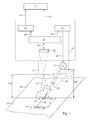
- FIGS. 2 to 4 show, with regard to the surface 02 of the material 01, different arrangements of the image sensor 06 and the illumination source 21 assigned to it can be provided.
- a matte surface 02 of the material 01 and / or its structure 03 an arrangement according to FIG. 1 or 2 is advantageous, wherein the optical axis 16 of the optical system 13 with the surface 02 of the material 01 a Angle ⁇ of 90 ° and the angle ⁇ between the optical axis 16 of the optics 13 and the optical axis 22 of the illumination source 21 is selected to be greater than 45 °.
- the light irradiated by the illumination source 21 onto the surface 02 of the material 01 then takes place as a grazing light.
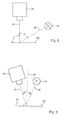
- a specular, highly reflective surface 02 of the material 01 and / or its structure 03 an arrangement according to FIG. 3 can lead to better results, wherein the incident on the surface 02 of the material 01 at an angle of incidence of 1 ⁇ 2 ⁇ light under a the Incident angle of 1 ⁇ 2 ⁇ at least almost corresponding angle of failure of also 1 ⁇ 2 ⁇ hits the image field of the image sensor 06, whereby at the pixels on the image field of the image sensor 06, a particularly high signal level is generated.
- a reflective surface 27 does not necessarily have to be arranged parallel to the other surface 02 of the material 01, as indicated by a dashed line in FIG. 3 and a solder 28 orthogonal to it.
- the arrangement of the image sensor 06 and its associated illumination source 21 is preferably determined by the orientation of the largest surface portion of the surface 27.
- Figs. 1 and 4 show a device with several, z. B. two illumination sources 21, which can be selectively used.
- the evaluation unit 07 controls z. B. the control device 23, whereby a switchover between the illumination sources 21 takes place.
- the illumination sources 21 each have different angles ⁇ 1 with their respective optical axis 22; ⁇ 2 to the surface 02; 27 of the material 01 on.
- the right in Fig. 4 illumination source 21 is preferably suitable for illuminating a shiny, reflective surface 02; 27, since with respect to the surface 02; 27 and the optical axis 16 of the image sensor 06 is arranged under the provision of incident angle equal to the angle of reflection, whereas the left in Fig. 4 illumination source 21 is more for illuminating a rough, matte Surface 02; 27 is suitable.
- an evaluation of at least one image acquisition of the image sensor that is not required to generate the signal 08 can be performed Be used 06 that the proposed device automatically to a condition of the surface 02; 27 of the material 01 adapts. If the evaluation of at least one image acquisition of the image sensor 06 which is not required to generate the signal 08 results in the image of the structure 03 being overexposed or underexposed on the image field of the image sensor 06, the evaluation unit 07 can be used for example. B. adjust the brightness of the illumination source 21 or the flash duration or, optionally, alternatively, the exposure time of the image field of the image sensor 06 automatically.
- the evaluation unit 07 can eg. B. switch between the multiple, controlled by her lighting sources 21 and one for the currently present surface 02; 27 of the material 01 bring more suitable illumination source 21 used, which thus for the currently present surface 02; 27 of the material 01 produces the highest image contrast for the structure 03 imaged on the image field of the image sensor 06.
- This automatic adaptation of the proposed device is preferably carried out before the next required for generating the signal 08 image acquisition. Due to the automatic adaptation, the proposed device becomes a self-learning system.
Landscapes
- Engineering & Computer Science (AREA)
- Mechanical Engineering (AREA)
- Length Measuring Devices By Optical Means (AREA)
- Inking, Control Or Cleaning Of Printing Machines (AREA)
- Reciprocating Conveyors (AREA)
- Investigating Materials By The Use Of Optical Means Adapted For Particular Applications (AREA)
Abstract
Description
Die Erfindung betrifft eine Vorrichtung zur Synchronisation eines Arbeitstaktes einer Einrichtung mit einem Bewegungsablauf eines entlang einer Bewegungsbahn bewegten Materials gemäß dem Oberbegriff des Anspruchs 1 sowie ein Verfahren zur Verwendung dieser Vorrichtung gemäß dem Oberbegriff des Anspruchs 75.The invention relates to a device for synchronizing a working cycle of a device with a sequence of movement of a moving material along a movement path according to the preamble of claim 1 and a method of using this device according to the preamble of claim 75.
Beispielsweise an einer Druckmaschine, z. B. einer Rollendruckmaschine oder einer Bogendruckmaschine, insbesondere in einer Offsetdruckmaschine, stellt sich das Problem, dass mit einer Bewegung eines durch die Druckmaschine bewegten Bedruckstoffes z. B. eine am Herstellprozess eines mit der Druckmaschine herzustellenden Druckerzeugnisses beteiligte oder eine den Druckprozess zur Qualitätskontrolle überwachende oder eine den Bedruckstoff fördernde Einrichtung der Druckmaschine zu synchronisieren oder zumindest zu steuern ist. Dabei kann im Herstellprozess des Druckerzeugnisses die Bewegung des Bedruckstoffes durch die Druckmaschine im Fall einer bahnförmigen Ausgestaltung des Bedruckstoffes z. B. mit einer Geschwindigkeit zwischen 10 m/s und 12 m/s oder im Fall einer bogenförmigen Ausgestaltung des Bedruckstoffes z. B. zwischen 15.000 Bogen/h und 18.000 Bogen/h oder jeweils mit noch größeren Geschwindigkeitswerten erfolgen.For example, on a printing press, z. B. a web-fed printing press or a sheet-fed press, especially in an offset printing press, the problem arises that with a movement of a moving through the printing press substrate z. B. involved in the manufacturing process of a printed product to be produced by the printing product or to monitor the printing process for quality control or to support a printing device of the printing press to synchronize or at least to control. In this case, in the manufacturing process of the printed product, the movement of the printing material through the printing press in the case of a web-like configuration of the printing material z. B. at a speed between 10 m / s and 12 m / s or in the case of an arcuate configuration of the substrate z. B. between 15,000 sheets / h and 18,000 sheets / h or in each case with even greater speed values.
Eine den Druckprozess überwachende Einrichtung kann ein Sensorsystem sein, wobei das Sensorsystem z. B. als ein bildgebendes System ausgebildet ist, wobei das bildgebende System z. B. eine Zeilenkamera aufweist, wobei die Zeilenkamera mit mindestens einer quer zur Transportrichtung des Bedruckstoffes gerichteten Zeile aus lichtempfindlichen Sensorelementen zumindest von einem Teil einer Oberfläche des Bedruckstoffes zeilenweise ein Bild aufnimmt. Die von der Zeilenkamera sequentiell aufgenommenen Bildzeilen führen aber nur dann zu einer sinnvollen Abbildung der Oberfläche des Bedruckstoffes, wenn die einzelnen aufgenommenen Bildzeilen stets mit vom bewegten Bedruckstoff in dessen Transportrichtung gerichteten, zurückgelegten Strecken gleicher Länge korrelieren, d. h. wenn die einzelnen aufgenommenen Bildzeilen möglichst äquidistant aufeinanderfolgen und in ihrer Aneinanderreihung möglichst lückenlos zumindest einen Teil der Oberfläche des Bedruckstoffes abbilden. Zur Synchronisation einer Zeilenkamera mit der Bewegung des Bedruckstoffes ist es erforderlich, dass das den Vorgang der Bildaufnahme synchronisierende Signal bereits nach sehr kurzen vom Bedruckstoff zurückgelegten Strecken und damit nach sehr kurzer Zeit vorliegt, wenn z. B. dasselbe auf dem Bedruckstoff aufgebrachte Druckbild durch eine Sequenz von Bildzeilen zumindest nahezu vollständig abgebildet werden soll. Die Länge einer solchen Strecke bemisst sich üblicherweise im Bereich von deutlich weniger als 1 mm.A printing process monitoring device may be a sensor system, wherein the sensor system z. B. is formed as an imaging system, wherein the imaging system z. B. has a line scan camera, wherein the line scan camera with at least one line of photosensitive sensor elements directed transversely to the transport direction of the printing material at least from a part of a surface of the Substrate line by line takes a picture. However, the image lines taken sequentially by the line scan camera only lead to a meaningful image of the surface of the printing material if the individual recorded image lines always correlate with traveled distances of the same length directed by the moving printing material in its transport direction, ie if the individual recorded image lines follow one another as equidistantly as possible and map in their juxtaposition as completely as possible at least part of the surface of the printing material. To synchronize a line scan camera with the movement of the printing material, it is necessary that the signal synchronizing the process of image recording already after very short distances traveled by the substrate and thus after a very short time, if z. B. the same applied to the substrate printed image should be at least almost completely imaged by a sequence of image lines. The length of such a route is usually measured in the range of significantly less than 1 mm.
Eine am Herstellprozess des Druckerzeugnisses beteiligte Einrichtung kann alternativ oder zusätzlich z. B. auch ein Perforator sein, insbesondere ein Laserperforator, mit dem in den Bedruckstoff zu dessen Teilung in konstante Abschnitte jeweils eine Perforation eingebracht wird, was wiederum nur dann zu guten Ergebnissen führt, wenn der Perforator genau zu solchen Zeitpunkten aktiviert wird, nachdem vom Bedruckstoff jeweils Strecken gleicher Länge zurückgelegt worden sind. In der Praxis ist es für die Herstellung von Druckerzeugnissen mit einer gleichen Abschnittslänge erforderlich, dass dieselbe vom Bedruckstoff zurückgelegte Strecke für eine große Anzahl von herzustellenden Druckerzeugnissen anhaltend hochgenau ermittelt wird. Während des Herstellprozesses soll demnach ein sich auf die Länge der Strecken auswirkender Störeinfluss vermieden werden.An involved in the manufacturing process of the printed matter device may alternatively or additionally z. B. also be a perforator, in particular a laser perforator, with each of which a perforation is introduced into the substrate to the division in constant sections, which in turn leads to good results, if the perforator is activated at precisely such times, after the substrate each distance of equal length have been covered. In practice, it is necessary for the production of printed products with an equal section length that the same distance traveled by the printing substrate for a large number of printed products to be produced is determined with consistently high accuracy. During the manufacturing process, therefore, a disturbing influence on the length of the sections should be avoided.
Ein Signal, mit dem die mit der Bewegung des Bedruckstoffes zu synchronisierende Einrichtung synchronisiert werden kann, kann z. B. dadurch gewonnen werden, dass mit einem Rotationskörper der Druckmaschine, insbesondere einem bedruckstoffführenden Zylinder oder einer bedruckstoffführenden Walze, ein Drehgeber verbunden ist, wobei der Drehgeber in Abhängigkeit von der Rotation des Rotationskörpers ein mit einer vom Bedruckstoff zurückgelegten Strecke korrelierendes Signal liefert, wobei das Signal von einer Steuereinrichtung zur Steuerung der zu synchronisierenden Einrichtung genutzt wird. Eine derartige Vorrichtung ist z. B. in der US 6,715,417 B2 beschrieben, wobei ein Encoder mit einem Formzylinder, einem Übertragungszylinder oder einem Gegendruckzylinder einer Druckmaschine koaxial verbunden ist, wobei ein vom Encoder bereitgestelltes, mit der Rotation der Zylinder korrelierendes Signal benutzt wird, um eine Lesezeit zur Aufnahme eines auf einem Bedruckstoff aufgebrachten Farbmessfeldes festzulegen, wobei auf eine weitere Ermittlung der Position des Bedruckstoffes verzichtet wird.A signal with which the device to be synchronized with the movement of the printing material can be synchronized, z. B. be obtained by that with a rotary body of the printing machine, in particular a printing material-carrying cylinder or a printing material-carrying roller, a rotary encoder is connected, wherein the rotary encoder in response to the rotation of the rotary body provides a correlated with a distance traveled by the printing material signal, the signal from a control device for controlling the synchronizing device is used. Such a device is z. Example, in US 6,715,417 B2, wherein an encoder with a forme cylinder, a transfer cylinder or a counter-pressure cylinder of a printing machine is coaxially connected, wherein an encoder provided by the correlating with the rotation of the cylinder signal is used to a reading time for receiving a To set a printing field applied color measuring field, which is dispensed with a further determination of the position of the printing material.
Ein Drehgeber liefert jedoch fehlerbehaftete Ergebnisse, sobald sich zwischen der Oberfläche des Bedruckstoffes und der Mantelfläche des Rotationskörpers ein Schlupf einstellt, der insbesondere dann nicht ausgeschlossen werden kann, wenn der Bedruckstoff den Rotationskörper nur teilweise umschlingt, was jedoch im Herstellprozess des Druckerzeugnisses in der Druckmaschine der Regelfall ist. Auch kann sich der Rotationskörper im Herstellprozess des Druckerzeugnisses abnutzen, was zu einer Veränderung seiner Umfangslänge führt. Aus diesen Gründen ist nicht gewährleistet, dass das vom Drehgeber generierte Signal anhaltend zuverlässig mit der vom Bedruckstoff tatsächlich zurückgelegten Strecke mit der z. B. zur Synchronisation einer Zeilenkamera oder eines Perforators erforderlichen Genauigkeit korreliert.However, a rotary encoder provides erroneous results as soon as a slip occurs between the surface of the printing material and the lateral surface of the rotary body, which can not be excluded in particular if the printing material wraps around the rotary body only partially, but in the manufacturing process of the printed product in the printing press Is the rule. Also, the rotating body may wear out in the manufacturing process of the printed product, resulting in a change in its circumferential length. For these reasons, it is not guaranteed that the signal generated by the encoder continued reliable with the actual distance traveled by the substrate with the z. B. correlated to the synchronization of a line scan camera or a perforator required accuracy.
Zur Vermeidung der Schlupfbildung ist auch der Einsatz eines gegen den Rotationskörper insbesondere federelastisch angestellten Reibrades mit einer z. B. gummierten Mantelfläche wenig hilfreich, weil durch den Berührungskontakt des Reibrades mit der Oberfläche des Bedruckstoffes der Bedruckstoff oder auch ein auf dessen Oberfläche aufgebrachtes Druckbild Schaden nehmen kann. Dieser Nachteil ist insbesondere bei der Herstellung hochwertiger Druckerzeugnisse nicht hinnehmbar, weshalb die Erzeugung des für die Synchronisation erforderlichen Signals berührungsfrei und für den Bedruckstoff rückwirkungsfrei erfolgen sollte. Im Übrigen kann auch ein Reibrad für einen zwischen ihm und dem Rotationskörper geführten Bedruckstoff Schlupf nicht völlig ausschließen.To avoid the formation of slippage and the use of a particular against the body rotation elastic spring friction wheel with a z. B. rubberized lateral surface little helpful, because by the contact of the friction wheel with the surface of the printing material of the substrate or even a printed image applied to the surface can take damage. This disadvantage is especially in the Production of high-quality printed products unacceptable, which is why the generation of the signal required for the synchronization should be non-contact and free of feedback for the substrate. Incidentally, a friction wheel for a guided between it and the rotating body printing slip can not be completely excluded.
Der Einsatz eines Drehgebers versagt auch z. B. an einer Bogendruckmaschine, bei der der Bedruckstoff nach Durchlaufen des letzten Druckwerks durch ein an einem Kettensystem geführtes Greifersystem transportiert wird, weil dieser ganz überwiegend keinen geeigneten Rotationskörper aufweisende Transportweg praktisch keine Möglichkeit zur Anordnung des Drehgebers bietet. Jedoch soll die Erzeugung des für die Synchronisation erforderlichen Signals auch z. B. für eine durch eine reine Linearbewegung geprägte Bewegung des Bedruckstoffes möglich sein.The use of a rotary encoder also fails z. B. on a sheet-fed press, in which the substrate is transported after passing through the last printing unit by a guided on a chain system gripper system, because this predominantly does not provide a suitable rotational body having transport path virtually no way to arrange the encoder. However, the generation of the signal required for synchronization should also z. B. be possible for a stamped by a pure linear motion movement of the printing material.
Aufgrund der Nachteile, die mit der Bewegungserfassung des Bedruckstoffes mittels eines an einen Rotationskörper angebrachten Drehgebers einhergehen, ist in der JP 10038901 A eine berührungslos arbeitende Geschwindigkeitsmessvorrichtung vorgeschlagen worden, wobei ein CCD-Flächenbildsensor von einem Teilbereich einer Materialbahn durch eine auf die Oberfläche der Materialbahn fokussierte Linse ein Bild aufnimmt und ein Bildprozessor ein Ausgangssignal des Bildsensors in einem Hochpassprozess hinsichtlich einer Geschwindigkeit der Materialbahn auswertet. Eine Steuerung oder gar eine Synchronisation einer mit hoher Präzision arbeitenden Einrichtung in Abhängigkeit von einer vom Bedruckstoff zurückgelegten Strecke ist jedoch mit der in der JP 10038901 A beschriebenen Geschwindigkeitsmessvorrichtung weder möglich, noch findet sich ein Hinweis darauf.Because of the disadvantages associated with motion detection of the substrate by means of a rotary encoder mounted on a rotary body, JP 10038901 A has proposed a non-contact speed measuring device, wherein a CCD area image sensor of a portion of a web of material focused by a focused on the surface of the web Lens takes an image and an image processor evaluates an output signal of the image sensor in a high-pass process with respect to a speed of the material web. However, control or even synchronization of a device operating with high precision as a function of a distance traveled by the printing material is neither possible with the speed measuring device described in JP 10038901 A, nor is there any indication of this.
Die vorliegende Erfindung geht davon aus, dass die Grundlage der Synchronisation einer mit hoher Präzision arbeitenden Einrichtung mit einer vom Bedruckstoff zurückgelegten Strecke eine in Echtzeit durchgeführte exakte Ermittlung der zurückgelegten Strecke des entlang einer Bewegungsbahn bewegten Bedruckstoffes ist. Zur Synchronisation der mit hoher Präzision arbeitenden Einrichtung mit der vom Bedruckstoff zurückgelegten Strecke muss die Ermittlung der Länge der Strecke in Anbetracht der hohen Geschwindigkeit, mit der die Bewegung des Bedruckstoffes durch die Druckmaschine erfolgt, sehr schnell und quasi verzögerungsfrei erfolgen.The present invention contemplates that the basis of synchronization of a high precision device with a path traveled by the substrate is a real time accurate determination of the distance traveled along the path of movement of the substrate. To synchronize with high-precision equipment with the distance covered by the substrate, the determination of the length of the distance must be carried out very quickly and virtually without delay in view of the high speed at which the movement of the printing material through the printing press.
Durch die DE 35 02 406 A1 sind ein Verfahren und eine Vorrichtung zur kontinuierlichen, berührungslosen Bestimmung der Länge eines ungeteilten, bewegten Körpers, insbesondere eines Stranggussmaterials, mit optisch spezifischer Oberflächenstruktur bekannt, wobei mit einer optischen Einrichtung zu zwei unterschiedlichen Zeitpunkten jeweils eine Momentaufnahme von dem bewegten Körper aufgenommen und gespeichert wird, wobei die beiden Momentaufnahmen bis auf einen durch die Bewegung des Körpers verursachten Versatz miteinander übereinstimmen, wobei aus dem Versatz eine Teillänge des Körpers bestimmt wird, wobei diese Bestimmung zyklisch mit hoher Geschwindigkeit erfolgt und wobei das Messsignal von einer Recheneinheit zur Steuerung einer dieser Längenmessvorrichtung nachgeschalteten Schneideinrichtung genutzt werden kann.DE 35 02 406 A1 discloses a method and a device for the continuous, non-contact determination of the length of an undivided, moving body, in particular a continuous casting, with optically specific surface structure, each with an optical device at two different times a snapshot of the moved body is recorded and stored, wherein the two snapshots coincide with each other except for an offset caused by the movement of the body, wherein the offset of a partial length of the body is determined, this determination is cyclically at high speed and wherein the measurement signal from a computing unit for controlling one of these length measuring device downstream cutting device can be used.
Der Erfindung liegt die Aufgabe zugrunde, eine Vorrichtung zur Synchronisation eines Arbeitstaktes einer Einrichtung mit einem Bewegungsablauf eines entlang einer Bewegungsbahn bewegten Materials sowie ein Verfahren zur Verwendung dieser Vorrichtung zu schaffen, wobei die Vorrichtung die Ermittlung einer vom Bedruckstoff mit hoher Geschwindigkeit zurückgelegten Strecke berührungslos in Echtzeit hochgenau durchgeführt.The invention has for its object to provide a device for synchronizing a working cycle of a device with a movement of a moving material along a movement path and a method for using this device, wherein the device, the determination of a distance traveled by the substrate at high speed distance in real time performed with high accuracy.
Die Aufgabe wird erfindungsgemäß durch die Merkmale des Anspruchs 1 oder 74 gelöst.The object is achieved by the features of claim 1 or 74.
Die mit der Erfindung erzielbaren Vorteile bestehen insbesondere darin, dass eine vom Material entlang einer Bewegungsbahn zurückgelegte Strecke selbst dann noch anhaltend zuverlässig hochgenau und auch für eine sehr kurze Länge der Strecke ermittelt werden kann, wenn sich das Material mit einer sehr hohen Geschwindigkeit bewegt. Die Ermittlung der vom Material zurückgelegten Strecke erfolgt berührungslos und damit verschleißfrei, und zwar sowohl an einer planen als auch an einer gewölbten Oberfläche des Materials. Auf der Grundlage der ermittelten Strecke wird in der bevorzugten Ausführung ein Signal generiert, um z. B. eine am Herstellprozess des mit der Druckmaschine herzustellenden Druckerzeugnisses beteiligte oder eine den Druckprozess überwachende oder eine den Bedruckstoff fördernde oder irgendeine andere mit hoher Präzision arbeitende Einrichtung der Druckmaschine mit der vom Material zurückgelegten Strecke zu synchronisieren oder zumindest zu steuern. Darüber hinaus lässt sich die vorgeschlagene Vorrichtung kostengünstig realisieren. Vorzugsweise ist eine Beleuchtungseinrichtung vorgesehen, die die vom Bildsensor vorgenommene Messung durch eine Kontrastveränderung oder eine Kontrastverstärkung begünstigt.The advantages that can be achieved with the invention are, in particular, that a distance traveled by the material along a path of movement can be reliably determined with high accuracy even for a very short length of the path even when the material is at a very high speed emotional. The determination of the distance covered by the material is non-contact and thus wear-free, both on a plane and on a curved surface of the material. On the basis of the determined distance, a signal is generated in the preferred embodiment, for. B. involved in the manufacturing process of the printing product to be produced by the printing press or to monitor the printing process or to convey the printing material or any other high-precision device of the printing press with the distance covered by the material or at least to control. In addition, the proposed device can be realized inexpensively. Preferably, a lighting device is provided which favors the measurement made by the image sensor by a change in contrast or a contrast enhancement.
Ein weiterer Vorteil besteht darin, dass auch eine zur Bewegungsbahn seitwärts gerichtete Bewegung des Materials detektierbar ist. Aus einer erkannten, z. B. unbeabsichtigten Seitwärtsbewegung des Materials kann ein Korrektursignal entweder zur Korrektur der Bewegung des Materials oder zur Nachführung eines von der Vorrichtung aufgenommenen Bildes generiert werden.Another advantage is that even a movement of the material directed sideways to the movement path can be detected. From a recognized, z. B. unintentional sideways movement of the material, a correction signal can be generated either to correct the movement of the material or to track an image taken by the device.
Ein Ausführungsbeispiel der Erfindung ist in den Zeichnungen dargestellt und wird im Folgenden näher beschrieben, wodurch weitere Vorteile deutlich werden.An embodiment of the invention is illustrated in the drawings and will be described in more detail below, whereby further advantages will become apparent.
Es zeigen:
- Fig. 1
- eine Prinzipdarstellung der vorgeschlagenen Vorrichtung;
- Fig. 2 bis 4
- hinsichtlich der Oberfläche des Materials unterschiedliche Anordnungen eines Bildsensors der Vorrichtung und einer ihm zugeordneten Beleuchtungsquelle.
- Fig. 1
- a schematic diagram of the proposed device;
- Fig. 2 to 4
- with respect to the surface of the material different arrangements of an image sensor of the device and an associated illumination source.
Gemäß der Fig. 1 weist die Vorrichtung zur Ermittlung einer von einem bewegten Material 01 entlang einer Bewegungsbahn B zurückgelegten Strecke S einen Bildsensor 06 auf, wobei das Material 01 eine zur Bewegungsbahn B parallele Oberfläche 02, d. h. in der Ebene der Bewegungsbahn B liegende Oberfläche 02 mit mindestens einer Struktur 03 aufweist, wobei der Bildsensor 06 zu mindestens zwei diskreten aufeinanderfolgenden Zeitpunkten in einem zu diesen Zeitpunkten jeweils gleichen Abbildungsmaßstab dieselbe Struktur 03 in einem Bild abbildet und mit dem jeweiligen Bild korrelierende Bilddaten 18 an eine Auswerteeinheit 07 leitet, wobei die zu unterschiedlichen Zeitpunkten generierten Bilddaten 18 in Relation zueinander infolge der Bewegung des Materials 01 eine Verschiebung der Struktur 03 aufweisen. Die Auswerteeinheit 07 ermittelt vorzugsweise rechnerisch aus der Verschiebung der Struktur 03 unter Berücksichtigung des Abbildungsmaßstabes die vom Material 01 zurückgelegte Strecke S. Bekannte, feste, d. h. unveränderliche mechanische Beziehungen z. B. in der Pixelanordnung des Bildsensors 06 können bei der Auswertung der Bilddaten 18 zur Quantifizierung der vom Material 01 zurückgelegten Strecke S als mechanische Referenz oder als Maßstab herangezogen werden.According to FIG. 1, the device for determining a distance S traveled by a moving
In der bevorzugten Ausführung setzt die Auswerteeinheit 07 nach einer vom Material 01 zurückgelegten Strecke S, vorzugsweise jeweils bei vom Material 01 zurückgelegten Strecken S gleicher Länge, ein Signal 08 zur Synchronisation eines mit der zurückgelegten Strecke S des Materials 01 zu synchronisierenden Vorgangs ab. Das von der Auswerteeinheit 07 abgesetzte und gegebenenfalls aufbereitete Signal 08 hat damit die Wirkung eines Taktgebers 09. Ein vom Taktgeber 09 zur Verfügung gestelltes, z. B. impulsartiges Signal 11, dessen taktgebende Eigenschaft in einer Ausführungsvariante auch bereits in dem von der Auswerteeinheit 07 abgesetzten Signal 08 enthalten sein kann, wird dazu genutzt, mindestens eine insbesondere mit hoher Präzision arbeitende Einrichtung 12 mit der vom Material 01 zurückgelegten Strecke S zu synchronisieren oder zu steuern. Die mindestens eine Einrichtung 12 ist somit eine in einem zu synchronisierenden Arbeitstakt arbeitende Einrichtung 12, d. h. der Arbeitsablauf dieser Einrichtung 12 ist in eine Vielzahl von wiederkehrenden Abschnitten untergliedert, wobei eine Länge bzw. Dauer dieser Abschnitte auf den Bewegungsablauf des entlang einer Bewegungsbahn B bewegten Materials 01 abzustimmen ist. Beispielsweise erfolgt nach jeder vom Material 01 zurückgelegten Strecke S genau ein Arbeitstakt der Einrichtung 12.In the preferred embodiment, the
Die mindestens eine Einrichtung 12 ist z. B. als eine das Material 01 in seinem Bearbeitungsprozess überwachende, bearbeitende oder fördernde Einrichtung 12 ausgebildet. Insbesondere ist die Einrichtung 12 als eine Zeilenkamera 12 oder als ein Perforator 12, vorzugsweise als ein Laserperforator 12, ausgebildet. Das vom Taktgeber 09 bereitgestellte Signal 11 kann auch dazu genutzt werden, mehrere Einrichtungen 12 mit der vom Material 01 zurückgelegten Strecke S des entlang der Bewegungsbahn B bewegten Materials 01 zu synchronisieren, z. B. eine Zeilenkamera 12 und einen Perforator 12 oder eine weitere das Material 01 in seinem Bearbeitungsprozess überwachende, bearbeitende oder fördernde Einrichtung 12.The at least one
Das Material 01 ist vorzugsweise ein Bedruckstoff 01, der z. B. in Form einer Materialbahn 01, z. B. einer Papierbahn 01 oder einer Folie 01, oder eines Bogens 01 oder mehrerer nacheinander zu bedruckender Bogen 01 ausgebildet ist.The
Die in der Fig. 1 durch einen Pfeil angedeutete Bewegungsbahn B des Materials 01 kann geradlinig oder gekrümmt entlang einer Bogenlinie verlaufen. In der bevorzugten Ausführung verläuft die Bewegungsbahn B des Materials 01 innerhalb einer in einem Offsetdruckverfahren arbeitenden Druckmaschine, wobei die Bewegungsbahn B auch entlang zumindest eines Teils einer Mantelfläche einer in der Druckmaschine angeordneten Walze oder eines dort angeordneten Zylinders verlaufen kann. Je nach Verlauf der Bewegungsbahn B ist die Oberfläche 02 des Materials 01 plan oder gewölbt, insbesondere konvex, ausgebildet.The movement path B of the material 01 indicated in FIG. 1 by an arrow can run in a straight line or curved along a curved line. In the preferred embodiment, the movement path B of the material 01 runs within a printing press operating in an offset printing method, wherein the movement path B can also run along at least part of a lateral surface of a roller arranged in the printing press or of a cylinder arranged there. Depending on the course of the movement path B, the
Die Struktur 03 des Materials 01 besteht vorzugsweise aus einem aus mikroskopisch kleinen Teilen bestehenden Gefüge, z. B. aus Fasern des Bedruckstoffes 01, insbesondere aus Papierfasern, aus einer auf der Oberfläche 02 des Materials 01 aufgetragenen ein- oder mehrlagigen Beschichtung, z. B. aus einer aufgebrachten Druckfarbe oder aus mehreren nacheinander übereinander aufgedruckten Druckfarben, oder aus einer Applikation des Materials 01. Die Struktur 03 des Materials 01 bildet vorzugsweise ein aus der Oberfläche 02 des Materials 01 erhaben heraustretendes oder in sie vertieftes Relief aus.The
Der Bildsensor 06 ist z. B. als ein Flächenbildsensor 06, vorzugsweise als eine einen CCD-Chip aufweisende Flächenkamera 06 ausgebildet. Der Bildsensor 06 ist insbesondere als eine Flächenkamera 06 mit einem teilauslesbaren CMOS-Bildsensor ausgebildet, wobei ein Bildfeld der Flächenkamera 06 anpassbar, insbesondere in seiner Größe einschränkbar ist. Die Größe des Bildfeldes der Flächenkamera 06 ist insbesondere an eine Bildwiederholrate der Flächenkamera 06 anpassbar. Das Bildfeld des Bildsensors 06 kann demnach unterschiedliche Betriebsstellungen aufweisen.The
Eine zwischen der Oberfläche 02 des Materials 01 und dem Bildsensor 06 angeordnete Optik 13, z. B. ein aus mindestens einer Linse und/oder aus mindestens einem Spiegel bestehendes optisches System, projiziert einen vorzugsweise rechteckigen Teil 14 der Oberfläche 02 des Materials 01, der in der Fig. 1 mit einer strichpunktierten Umrandung dargestellt ist, entlang einer optischen Achse 16 auf das Bildfeld des Bildsensors 06, wobei die optische Achse 16 mit der Oberfläche 02 des Materials 01 einen Winkel γ von z. B. 45° bis 90° bildet. Der auf das Bildfeld des Bildsensors 06 projizierte Teil 14 der Oberfläche 02 des Materials 01 bestimmt für den vorzugsweise ortsfest angeordneten Bildsensor 06 einen Abtastort 14. Zwischen der Oberfläche 02 des Materials 01 und einer der Oberfläche 02 des Materials 01 zugewandten Stirnseite 17 der Optik 13 verbleibt ein Abstand A13, der von einem mechanisch beweglichen Element, z. B. von einer Handhabungseinrichtung der Druckmaschine, insbesondere von einem Greifersystem, bei Bedarf durchlaufen werden kann. Die mindestens eine Vorrichtung zur Ermittlung einer vom bewegten Material 01 entlang der Bewegungsbahn B zurückgelegten Strecke S arbeitet somit in jedem Fall hinsichtlich der Oberfläche 02 des Materials 01 berührungslos. Der Abstand A13 bemisst sich im Bereich zwischen 10 mm und 1.000 mm, vorzugsweise zwischen 50 mm und 400 mm.An arranged between the
Die Optik 13 bildet den Teil 14 der Oberfläche 02 des Materials 01, insbesondere die in diesem Teil 14 der Oberfläche 02 des Materials 01 enthaltene Struktur 03, zu mehreren aufeinanderfolgenden diskreten Zeitpunkten in einem zu diesen Zeitpunkten jeweils gleichen Abbildungsmaßstab auf dem Bildfeld des Bildsensors 06 ab. Aufgrund der Kleinheit der Struktur 03 wird der Abbildungsmaßstab derart gewählt, dass die Abbildung der Struktur 03 auf dem Bildfeld des Bildsensors 06 im Maßstab 1:1 oder sogar in Form einer Vergrößerung erfolgt. Der Bildsensor 06 weist zumindest in seinem Bildfeld eine geeignete Auflösung hinsichtlich seiner Pixel auf. Die Optik 13 ist z. B. als ein telezentrisches Objektiv ausgebildet, damit eine z. B. durch Schwingungen des Materials 01 hervorgerufene Veränderung des Abstands A13 die Abbildung der Struktur 03 auf dem Bildfeld des Bildsensors 06 möglichst nicht oder nur sehr geringfügig verändert. Insbesondere bei der Abbildung der Oberfläche 02 eines sehr dünnen, weichen Materials 01, z. B. von Papier geringer Grammatur oder von einer z. B. aus einem Kunststoff bestehenden Folie, ist die Verwendung einer telezentrischen Optik 13 vorteilhaft, weil eine telezentrische Optik 13 eine leichte Abstandsvariation, wie sie beim Transport von sehr dünnem, weichem Material 01 z. B. durch Schwingungen und/oder Wellenbildung auftreten kann, kompensiert, weshalb z. B. durch Schwingungen und/oder Wellenbildung hervorgerufene Abstandsvariationen nicht sofort zu einer negativen Beeinflussung des Messergebnisses führen. Im Übrigen ermöglicht die Verwendung einer telezentrischen Optik 13 auch eine fehlerfreie Erfassung der Oberfläche 02 eines entlang einer gekrümmten bzw. gewölbten Bewegungsbahn B geführten Materials 01. Die Verwendung einer telezentrischen Optik 13 erspart eine Nachführung des Messabstandes, d. h. insbesondere des Abstandes A13. Wegen der Abstandstoleranz der telezentrischen Optik 13 ist auch eine Nachkalibrierung z. B. der die Bilddaten 18 des Bildsensors 06 auswertenden Auswerteeinheit 07 nicht erforderlich.The
In der Auswerteeinheit 07 werden die vom Bildsensor 06 zugeleiteten Bilddaten 18, die mit Bildern korrelieren, die der Bildsensor 06 zu zwei unterschiedlichen Zeitpunkten von derselben Struktur 03 aufgenommen hat, mit einem geeigneten Algorithmus, z. B. einem Korrelationsverfahren, analysiert und z. B. durch eine Messung dahingehend ausgewertet, welche Verschiebung die Struktur 03 infolge der zwischenzeitlichen Bewegung des Materials 01 genommen hat. Dabei wird die Verschiebung der Struktur 03 zumindest hinsichtlich der Länge des Verschiebungsvektors quantifiziert. Unter Berücksichtigung des Abbildungsmaßstabes ermittelt die Auswerteeinheit 07 dann die vom Material 01 zurückgelegte Strecke S.In the
In dem zweidimensionalen Bildfeld des Bildsensors 06 kann auch eine zur Bewegungsbahn B des Materials 01 seitliche Verschiebung festgestellt werden, indem die Auswerteeinheit 07 die Richtung der Verschiebung und gegebenenfalls das Maß des aus der Verschiebung erkannten seitlichen Versatzes der Struktur 03 ermittelt. Damit kann die Auswerteeinheit 07 ein weiteres Signal 19, gegebenenfalls nach einer entsprechenden Aufbereitung oder Verstärkung, zur Verfügung stellen, das mit dem seitlichen Versatz der Struktur 03 und damit auch mit dem die Struktur 03 ortsfest aufweisenden Material 01 korreliert, wobei auch dieses Signal 19 dazu genutzt werden kann, mindestens eine weitere Einrichtung, insbesondere die mit hoher Präzision arbeitende Einrichtung 12, zu steuern. Das zweidimensionale Bildfeld des Bildsensors 06 kann auch dahingehend genutzt werden, ein präzises, immer gleichartiges Abbild von der Struktur 03 zu erzeugen, indem eine Seitwärtsbewegung des Materials 01 in der die Bilddaten 18 des Bildsensors 06 auswertenden Auswerteeinheit 07 durch Anwendung eines Korrekturverfahrens, z. B. eines bildverarbeitenden Verfahrens, rechnerisch ausgeglichen wird, sodass die von der Auswerteeinheit 07 vorgenommene Ermittlung der vom Material 01 zurückgelegten Strecke S unbeeinflusst von der Seitwärtsbewegung des Materials 01 erfolgt. Eine Seitwärtsbewegung des Materials 01 kann z. B. die Folge von toleranzbehafteten, fehleingestellten, abgenutzten und/oder sogar beschädigten Führungselementen zur Führung des Materials 01 sein. Ein zur Anwendung bringbares Korrekturverfahren kann vorsehen, ein Startpixel einer jeden Bildzeile des Bildsensors 06 jeweils in Abhängigkeit von dem mit dem seitlichen Versatz der Struktur 03 korrelierenden Signal 19 festzulegen oder neu zu definieren, sobald das Signal 19 einen zuvor festgelegten, z. B. in der Auswerteeinheit 07 gespeicherten Grenzwert erreicht oder überschreitet.In the two-dimensional image field of the
Die zur Synchronisation der Einrichtung 12 erforderlichen Signale 08; 11 oder das zur Steuerung einer Einrichtung hinsichtlich einer Seitwärtsbewegung des Materials 01 benötigte Signal 19 können deshalb in Echtzeit bereitgestellt werden, weil die Verschiebung einer sich entlang ihres Verschiebungsweges in ihrer Gestalt nicht verändernden Struktur 03 von der Auswerteeinheit 07 schnell ausgewertet werden kann, wobei sich, wie bereits beschrieben, die Verschiebung aus zu zwei unterschiedlichen Zeitpunkten generierten Bilddaten 18 in ihrer Relation zueinander infolge der Bewegung des Materials 01 ergibt. Die Struktur 03 bleibt also zu mindestens zwei unterschiedlichen Zeitpunkten, zu denen der Bildsensor 06 sie abbildet, in ihrer Gestalt unverändert. Nach der Abbildung der Struktur 03 auf dem Bildfeld des Bildsensors 06 zu einem ersten Zeitpunkt muss die Auswerteeinheit 07 lediglich festzustellen, welche Koordinaten diese nunmehr bekannte Struktur 03 zu einem zweiten Zeitpunkt innerhalb des Bildfeldes des Bildsensors 06 aufweist und die Veränderung in den Koordinaten z. B. durch eine Differenzbildung bestimmen, wobei die Koordinaten eine Lage zumindest eines Teils der Struktur 03 innerhalb des Bildfeldes des Bildsensors 06 bestimmen. Das von der Auswerteeinheit 07 angewendete Auswertungsverfahren setzt demnach voraus, dass die zu mindestens zwei unterschiedlichen Zeitpunkten generierten Bilddaten 18 hinsichtlich des die Struktur 03 aufweisenden Bildfeldes des Bildsensors 06 einen ausreichenden Überlappungsbereich aufweisen und dass beide Bilddaten 18 die Struktur 03 zumindest teilweise abbilden. Die Bildwiederholrate des Bildsensors 06 ist vorzugsweise an die Geschwindigkeit des bewegten Materials 01 angepasst oder zumindest anpassbar. Falls die Geschwindigkeit des bewegten Materials 01 sehr gering ist, kann die zwischen zwei aufeinanderfolgenden Bildaufnahmen zurückgelegte Strecke S des Materials 01 für die Bildwiederholrate des Bildsensors 06 limitierend wirken, weil die aufeinanderfolgenden Bildaufnahmen den erwähnten ausreichenden Überlappungsbereich aufweisen müssen, damit die Verschiebung der Struktur 03 innerhalb des Bildfeldes des Bildsensors 06 ermittelt werden kann. In diesem Fall der geringen Geschwindigkeit des bewegten Materials 01 ist ein Zwischentakt sicher durch eine Interpolation oder eine Extrapolation aus vorangegangenen Bildaufnahmen ermittelbar.The signals required for the synchronization of the
Die vorgeschlagene Vorrichtung weist demnach insbesondere die Vorteile auf, dass sie die vom bewegten Material 01 zurückgelegte Strecke S aufgrund der verfahrensbedingt geringen Auswertungszeit schnell ermittelt, und darüber hinaus in der Lage ist, auch eine Verschiebung von nur sehr geringer Länge zu ermitteln und zu quantifizieren. Deshalb kann die vorgeschlagene Vorrichtung auch verwendet werden, um Bildzeilen einer Zeilenkamera 12 zu synchronisieren. Dabei ist die Bildwiederholrate des Bildsensors 06 deutlich höher als der Zeilentakt der Zeilenkamera 12. Die Länge des Verschiebungsvektors der von der Auswerteeinheit 07 auszuwertenden Verschiebung der Struktur 03 ist auch dann außerordentlich klein, wenn die vom bewegten Material 01 zwischen zwei Bildaufnahmen zurückgelegte Strecke S im Bereich einer Ortsunschärfe der von der Auswerteeinheit 07 anzusteuernden Einrichtung 12 liegt.The proposed device accordingly has the particular advantages that it quickly determines the distance S traveled by the moving
Es ist von Vorteil, den Abtastort 14 des Bildsensors 06, d. h. den auf das Bildfeld des Bildsensors 06 projizierten Teil 14 der Oberfläche 02 des Materials 01, möglichst nah an denjenigen Ort zu legen, an dem eine zu synchronisierende oder zumindest zu steuernde Einrichtung 12 auf das Material 01 einwirkt. So kann der Abtastort 14 des Bildsensors 06 z. B. die zeilenförmige Abtastspur einer zu synchronisierenden Zeilenkamera 12 zumindest teilweise überdecken. Dadurch ist die aus der Bildaufnahme und Bildauswertung bestehende und z. B. auf die Zeilenkamera 12 wirkende Steuerkette resistent gegen eine spontane Änderung der Geschwindigkeit des Materials 01.It is advantageous to place the
Vorzugsweise ist eine zumindest den Abtastort 14 des Bildsensors 06 ausleuchtende Beleuchtungsquelle 21 vorgesehen, wobei die Beleuchtungsquelle 21 z. B. als eine Konstantlichtquelle 21 oder als eine Blitzlichtquelle 21 ausgeführt ist. Die Helligkeit der Beleuchtungsquelle 21 oder deren Blitzdauer oder gegebenenfalls alternativ auch die Belichtungsdauer des Bildfeldes des Bildsensors 06 sind z. B. an die jeweilige Beschaffenheit der Oberfläche 02 des Materials 01 angepasst oder zumindest anpassbar. Insbesondere wenn sich der Abtastort 14 des Bildsensors 06 und die zeilenförmige Abtastspur einer zu synchronisierenden Zeilenkamera 12 zumindest teilweise überdecken, werden die Lichtfarbe der Beleuchtungsquelle 21 und die Farbempfindlichkeit des Bildfeldes des Bildsensors 06 vorteilhafterweise derart gewählt, dass sie außerhalb des von der Zeilenkamera 12 für ihre Bilderfassung genutzten Spektralbereiches liegen, um eine gegenseitige Störung von Zeilenkamera 12 und Bildsensor 06 zu vermeiden. Wenn die Bildaufnahme der Zeilenkamera 12 z. B. im sichtbaren Spektrum erfolgt, kann für die Farbempfindlichkeit des Bildfeldes des Bildsensors 06 und die daran angepasste Lichtfarbe der Beleuchtungsquelle 21 der Bereich z. B. der infraroten oder ultravioletten Strahlung genutzt werden. Dadurch ist sichergestellt, dass die Zeilenkamera 12 und der Bildsensor 06 bezüglich ihrer jeweiligen Bildaufnahmen unabhängig voneinander und ohne gegenseitige Störung arbeiten, da ihre jeweilige spektrale Empfindlichkeit durch die unterschiedlich gewählten Spektralbereiche überschneidungsfrei ist, auch wenn der Abtastort 14 des Bildsensors 06 und die zeilenförmige Abtastspur der zu synchronisierenden Zeilenkamera 12 örtlich zusammenfallen.Preferably, at least the
Die Beleuchtungsquelle 21 ist gleichfalls wie die zum Bildsensor 06 gehörende Optik 13 von der Oberfläche 02 des Materials 01 beabstandet angeordnet, z. B. in einem Abstand A21, wobei der Abstand A21 von einem mechanisch beweglichen Element, z. B. von einer Handhabungseinrichtung der Druckmaschine, insbesondere von einem Greifersystem, bei Bedarf durchlaufen werden kann. Der Abstand A21 misst z. B. im Bereich zwischen 30 mm und 200 mm, vorzugsweise zwischen 80 mm und 140 mm.The
Die Beleuchtungsquelle 21 ist zur Oberfläche 02 des Materials 01 derart angeordnet, dass mit dem von der Beleuchtungsquelle 21 emittierten Licht die Struktur 03 auf der Oberfläche 02 des Materials 01 hervorgehoben wird. Dazu ist die Beleuchtungsquelle 21 mit ihrer optischen Achse 22 unter einem Winkel α zur optischen Achse 16 der Optik 13 angeordnet, wobei der Winkel α z. B. zwischen 0° und 90° liegt, insbesondere zwischen 45° und 90°. Dasvon der Beleuchtungsquelle 21 entlang ihrer optischen Achse 22 unter dem Winkel α auf die Oberfläche 02 des Materials 01 eingestrahlte Licht erzeugt dann einen Schattenwurf von der Struktur 03, wodurch Bildkontraste verstärkt werden. Ein Raumwinkel ω, unter dem die Beleuchtungsquelle 21 ihr Licht aussendet, ist vorzugsweise eng bemessen und liegt z. B. zwischen 0,00006 sr und 0,05 sr.The
Für unterschiedliche Beschaffenheiten der Oberfläche 02 des Materials 01 und dessen Struktur 03 können verschiedene Anordnungen der Beleuchtungsquelle 21 von Vorteil sein, wobei sich die Anordnungen z. B. im Abstand A21 der Beleuchtungsquelle 21 von der Oberfläche 02 des Materials 01 oder in dem Winkel α, den die Beleuchtungsquelle 21 mit ihrer optischen Achse 22 zur optischen Achse 16 der Optik 13 einnimmt, unterscheiden. Zwei verschiedene Anordnungen der Beleuchtungsquelle 21 sind in der Fig. 1 beispielhaft dargestellt. In jedem Fall kann die Auswerteeinheit 07 mit einem an eine Steuereinrichtung 23 übertragenen Signal 24 den Betrieb und gegebenenfalls auch die Betriebsstellung der Beleuchtungsquelle 21 steuern, wobei die Steuereinrichtung 23 mit einem entsprechenden Signal 26 ihrerseits auf die Beleuchtungsquelle 21 einwirkt.For different textures of the
Wie die Fig. 2 bis 4 zeigen, können hinsichtlich der Oberfläche 02 des Materials 01 unterschiedliche Anordnungen des Bildsensors 06 und der ihm zugeordneten Beleuchtungsquelle 21 vorgesehen sein. Für eine matte Oberfläche 02 des Materials 01 und/oder dessen Struktur 03 ist eine Anordnung gemäß der Fig. 1 oder 2 vorteilhaft, wobei die optische Achse 16 der Optik 13 mit der Oberfläche 02 des Materials 01 einen Winkel γ von 90° bildet und der Winkelα zwischen der optischen Achse 16 der Optik 13 und der optischen Achse 22 der Beleuchtungsquelle 21 größer als 45° gewählt ist. Das von der Beleuchtungsquelle 21 auf die Oberfläche 02 des Materials 01 eingestrahlte Licht erfolgt dann als ein Streiflicht.As FIGS. 2 to 4 show, with regard to the
Für eine spiegelnde, stark reflektive Oberfläche 02 des Materials 01 und/oder dessen Struktur 03 kann eine Anordnung gemäß der Fig. 3 zu besseren Ergebnissen führen, wobei das auf die Oberfläche 02 des Materials 01 unter einem Einfallswinkel von ½ α eingestrahlte Licht unter einem dem Einfallswinkel von ½ α zumindest nahezu entsprechenden Ausfallswinkel von gleichfalls ½ α auf das Bildfeld des Bildsensors 06 trifft, wodurch an den Pixeln auf dem Bildfeld des Bildsensors 06 ein besonders hoher Signalpegel erzeugt wird. Eine reflektive Oberfläche 27 muss hierbei nicht zwangsläufig parallel zu der übrigen Oberfläche 02 des Materials 01 angeordnet sein, wie das in der Fig. 3 durch eine gestrichelte Linie und ein orthogonal auf ihr stehendes Lot 28 angedeutet ist. Bei einer am Abtastort 14 nicht homogen eben, sondern z. B. wellenförmig oder rampenförmig ausgebildeten Oberfläche 27 wird die Anordnung vom Bildsensor 06 und der ihr zugeordneten Beleuchtungsquelle 21 vorzugsweise von der Ausrichtung des größten Oberflächenanteils der Oberfläche 27 bestimmt.For a specular, highly
Fig. 1 und 4 zeigen eine Vorrichtung mit mehreren, z. B. zwei Beleuchtungsquellen 21, die wahlweise zum Einsatz gebracht werden können. Zu diesem Zweck steuert die Auswerteeinheit 07 z. B. die Steuereinrichtung 23 an, wodurch eine Umschaltung zwischen den Beleuchtungsquellen 21 erfolgt. Die Beleuchtungsquellen 21 weisen mit ihrer jeweiligen optischen Achse 22 jeweils vorzugsweise unterschiedliche Winkel β1; β2 zur Oberfläche 02; 27 des Materials 01 auf. Die in der Fig. 4 rechte Beleuchtungsquelle 21 eignet sich vorzugsweise zur Beleuchtung einer glänzenden, reflektiven Oberfläche 02; 27, da sie bezüglich der Oberfläche 02; 27 und der optischen Achse 16 des Bildsensors 06 unter der Maßgabe Einfallswinkel gleich Ausfallswinkel angeordnet ist, wohingegen die in der Fig. 4 linke Beleuchtungsquelle 21 eher zur Beleuchtung einer rauen, matten Oberfläche 02; 27 geeignet ist.Figs. 1 and 4 show a device with several, z. B. two
Insbesondere wenn die Bildwiederholrate des Bildsensors 06 höher ist, als es zur Erzeugung des Signals 08 zur Synchronisation eines mit der zurückgelegten Strecke S des Materials 01 zu synchronisierenden Vorgangs erforderlich ist, kann eine Auswertung von mindestens einer zur Erzeugung des Signals 08 nicht erforderlichen Bildaufnahme des Bildsensors 06 dazu verwendet werden, dass sich die vorgeschlagene Vorrichtung selbsttätig an eine Beschaffenheit der Oberfläche 02; 27 des Materials 01 anpasst. Wenn die Auswertung von mindestens einer zur Erzeugung des Signals 08 nicht erforderlichen Bildaufnahme des Bildsensors 06 ergibt, dass die Abbildung der Struktur 03 auf dem Bildfeld des Bildsensors 06 überbelichtet oder unterbelichtet ist, kann die Auswerteeinheit 07 z. B. die Helligkeit der Beleuchtungsquelle 21 oder deren Blitzdauer oder gegebenenfalls alternativ auch die Belichtungsdauer des Bildfeldes des Bildsensors 06 selbsttätig anpassen. Wenn die Auswertung von mindestens einer zur Erzeugung des Signals 08 nicht erforderlichen Bildaufnahme des Bildsensors 06 ergibt, dass der Bildkontrast der auf dem Bildfeld des Bildsensors 06 abgebildeten Struktur 03 zu gering ist und damit einen voreingestellten Schwellwert unterschreitet, kann die Auswerteeinheit 07 z. B. zwischen den mehreren, von ihr angesteuerten Beleuchtungsquellen 21 umschalten und eine für die aktuell vorliegende Oberfläche 02; 27 des Materials 01 geeignetere Beleuchtungsquelle 21 zum Einsatz bringen, welche somit für die aktuell vorliegende Oberfläche 02; 27 des Materials 01 den höchsten Bildkontrast für die auf dem Bildfeld des Bildsensors 06 abgebildete Struktur 03 erzeugt. Diese selbsttätige Anpassung der vorgeschlagenen Vorrichtung erfolgt vorzugsweise vor der nächsten zur Erzeugung des Signals 08 erforderlichen Bildaufnahme. Durch die selbsttätige Anpassung wird die vorgeschlagene Vorrichtung zu einem selbstlernenden System.In particular, if the image refresh rate of the
- 0101
- Material, Bedruckstoff, Materialbahn, Papierbahn, Folie, BogenMaterial, substrate, web, paper web, foil, sheet
- 0202
- Oberflächesurface
- 0303
- Strukturstructure
- 0404
- --
- 0505
- --
- 0606
- Bildsensor, Flächenbildsensor, FlächenkameraImage sensor, area image sensor, area camera
- 0707
- Auswerteeinheitevaluation
- 0808
- Signalsignal
- 0909
- Taktgeberclock
- 1010
- --
- 1111
- Signalsignal
- 1212
- Einrichtung, Zeilenkamera, Perforator, LaserperforatorSet up, line scan camera, perforator, laser perforator
- 1313
- Optikoptics
- 1414
- Teil der Oberfläche (02), AbtastortPart of the surface (02), scanning location
- 1515
- --
- 1616
- optische Achse (06; 13)optical axis (06; 13)
- 1717
- Stirnseitefront
- 1818
- Bilddatenimage data
- 1919
- Signalsignal
- 2020
- --
- 2121
- Beleuchtungsquelle, Konstantlichtquelle, BlitzlichtquelleIllumination source, constant light source, flash light source
- 2222
- optische Achse (21)optical axis (21)
- 2323
- Steuereinrichtungcontrol device
- 2424
- Signalsignal
- 2525
- --
- 2626
- Signalsignal
- 2727
- Oberflächesurface
- 2828
- Lotsolder
- A13A13
- Abstanddistance
- A21A21
- Abstanddistance
- BB
- Bewegungsbahntrajectory
- SS
- Streckeroute
- αα
- Winkelangle
- β1; β2β1; β2
- Winkelangle
- γγ
- Winkelangle
- ωω
- Raumwinkelsolid angle
Claims (77)
Applications Claiming Priority (1)
| Application Number | Priority Date | Filing Date | Title |
|---|---|---|---|
| DE102004033660A DE102004033660B4 (en) | 2004-07-12 | 2004-07-12 | Device for determining a distance traveled by a moving material along a movement path |
Publications (3)
| Publication Number | Publication Date |
|---|---|
| EP1619154A2 true EP1619154A2 (en) | 2006-01-25 |
| EP1619154A3 EP1619154A3 (en) | 2007-02-28 |
| EP1619154B1 EP1619154B1 (en) | 2010-09-01 |
Family
ID=35266778
Family Applications (1)
| Application Number | Title | Priority Date | Filing Date |
|---|---|---|---|
| EP05106286A Not-in-force EP1619154B1 (en) | 2004-07-12 | 2005-07-11 | Device for the synchronization of an operation cycle of a device with the sequence of movement of a material moved along a path and method for the use of this device |
Country Status (3)
| Country | Link |
|---|---|
| EP (1) | EP1619154B1 (en) |
| AT (1) | ATE479621T1 (en) |
| DE (2) | DE102004033660B4 (en) |
Cited By (3)
| Publication number | Priority date | Publication date | Assignee | Title |
|---|---|---|---|---|
| EP2028144A3 (en) * | 2007-08-21 | 2009-11-18 | Koenig & Bauer AG | Device for monitoring and/or controlling a running web in a rotary printer and method for monitoring the running web |
| EP2269824A1 (en) * | 2009-07-01 | 2011-01-05 | ELTROMAT GmbH | Method and device for monitoring the registered processing of web-like material in installations |
| DE202010012725U1 (en) * | 2010-09-16 | 2011-12-19 | Emima Gmbh | Location of a moving object |
Families Citing this family (3)
| Publication number | Priority date | Publication date | Assignee | Title |
|---|---|---|---|---|
| DE102012101310C5 (en) * | 2012-02-17 | 2014-09-04 | Stephan Krebs | Apparatus and method for image control |
| DE102016220759A1 (en) * | 2016-10-21 | 2018-04-26 | Texmag Gmbh Vertriebsgesellschaft | Method and device for compensating a material web offset during material web inspection |
| DE102017213262B4 (en) * | 2017-08-01 | 2022-09-22 | Heidelberger Druckmaschinen Ag | Image acquisition with area-by-area image resolution |
Citations (3)
| Publication number | Priority date | Publication date | Assignee | Title |
|---|---|---|---|---|
| DE3502406A1 (en) | 1985-01-22 | 1986-07-24 | Dr. Peter + Steinwender Technische Geräte GmbH, 8176 Waakirchen | Method and device for the continuous non-contact measurement of the length of an integral moving body |
| JPH1038901A (en) | 1996-07-19 | 1998-02-13 | Futec Inc | Noncontact speedometer |
| US6715417B2 (en) | 2000-10-13 | 2004-04-06 | Dainippon Screen Mfg. Co., Ltd. | Printing press equipped with color chart measuring apparatus |
Family Cites Families (6)
| Publication number | Priority date | Publication date | Assignee | Title |
|---|---|---|---|---|
| GB9214664D0 (en) * | 1992-07-10 | 1992-08-19 | Wiggins Teape Group Ltd | Watermark detection |
| DE4428156A1 (en) * | 1994-08-09 | 1995-08-10 | Siemens Nixdorf Inf Syst | Record carrier speed determn. method in electrographic printer |
| DE19631747A1 (en) * | 1996-08-06 | 1997-09-11 | Oce Printing Systems Gmbh | Sensor device for detecting marking of moving continuous recording medium |
| SE9701911D0 (en) * | 1997-05-22 | 1997-05-22 | Optronic Consult Ab | Method and device for contactless measurement of movement |
| US7130710B2 (en) * | 2002-08-07 | 2006-10-31 | Kimberly-Clark Worldwide, Inc. | System and method for tracking and exploiting per station information from a multiple repeat manufacturing device |
| DE10338973B4 (en) * | 2002-09-30 | 2013-01-31 | Goss International Montataire S.A. | Method and device for fault detection during transport of a material web |
-
2004
- 2004-07-12 DE DE102004033660A patent/DE102004033660B4/en not_active Expired - Fee Related
-
2005
- 2005-07-11 EP EP05106286A patent/EP1619154B1/en not_active Not-in-force
- 2005-07-11 AT AT05106286T patent/ATE479621T1/en active
- 2005-07-11 DE DE502005010163T patent/DE502005010163D1/en active Active
Patent Citations (3)
| Publication number | Priority date | Publication date | Assignee | Title |
|---|---|---|---|---|
| DE3502406A1 (en) | 1985-01-22 | 1986-07-24 | Dr. Peter + Steinwender Technische Geräte GmbH, 8176 Waakirchen | Method and device for the continuous non-contact measurement of the length of an integral moving body |
| JPH1038901A (en) | 1996-07-19 | 1998-02-13 | Futec Inc | Noncontact speedometer |
| US6715417B2 (en) | 2000-10-13 | 2004-04-06 | Dainippon Screen Mfg. Co., Ltd. | Printing press equipped with color chart measuring apparatus |
Cited By (4)
| Publication number | Priority date | Publication date | Assignee | Title |
|---|---|---|---|---|
| EP2028144A3 (en) * | 2007-08-21 | 2009-11-18 | Koenig & Bauer AG | Device for monitoring and/or controlling a running web in a rotary printer and method for monitoring the running web |
| EP2210839A3 (en) * | 2007-08-21 | 2010-12-08 | Koenig & Bauer Aktiengesellschaft | Device for monitoring and/or controlling a running web in a rotary printer and method for monitoring the running web |
| EP2269824A1 (en) * | 2009-07-01 | 2011-01-05 | ELTROMAT GmbH | Method and device for monitoring the registered processing of web-like material in installations |
| DE202010012725U1 (en) * | 2010-09-16 | 2011-12-19 | Emima Gmbh | Location of a moving object |
Also Published As
| Publication number | Publication date |
|---|---|
| DE502005010163D1 (en) | 2010-10-14 |
| EP1619154B1 (en) | 2010-09-01 |
| DE102004033660B4 (en) | 2008-03-13 |
| ATE479621T1 (en) | 2010-09-15 |
| DE102004033660A1 (en) | 2006-02-09 |
| EP1619154A3 (en) | 2007-02-28 |
Similar Documents
| Publication | Publication Date | Title |
|---|---|---|
| DE69314397T2 (en) | Detect watermarks | |
| EP3278302B1 (en) | Motion-measuring system of a machine and method for operating the motion-measuring system | |
| DE60316148T2 (en) | WAY MEASURING SYSTEM AND THIS INCLUDING ARC SUPPLY SYSTEM | |
| EP0884181B1 (en) | Process for regulating operations carried out by a printing machine | |
| DE10135010A1 (en) | Printing product conveyor control device for printing machine synchronizes recording operation with operation of conveyor, based on comparison of stray light distribution with prescribed distribution | |
| DE19940217C2 (en) | Method for contactless measurement of the change in the spatial shape of a test sample, in particular for measuring the change in length of the test sample subject to an external force, and device for carrying out the method | |
| EP1619154B1 (en) | Device for the synchronization of an operation cycle of a device with the sequence of movement of a material moved along a path and method for the use of this device | |
| EP1714786A2 (en) | Device for inspecting printed products | |
| DE4244276A1 (en) | Arrangement for measuring the position of a sheet edge on the surface of a rotating cylinder | |
| EP2589926A1 (en) | Device for and method of optically measuring the shape of moving objects | |
| DE102006004060B4 (en) | Method and device for measuring the height and / or height profile of an object | |
| DE102009023948B4 (en) | Device for detecting a mark on a flat object and method therefor, and device for separating sections from a flat object | |
| DE19733297C2 (en) | Non-contact optical thickness measurement | |
| EP3655175B1 (en) | Method for operating a processing installation with a movable punch | |
| DE202015104751U1 (en) | Device for inspecting products arranged on a material web | |
| EP3312114B1 (en) | Method and device for detecting the position of a moving web | |
| WO2009018894A1 (en) | Method and device for determining geometric data of a measured object | |
| EP3657125A1 (en) | Device and method for determining variations in flatness when handling a material in the form of a strip | |
| DE10215548B4 (en) | Method and device for detecting scanning positions in printed images | |
| DE102007006333A1 (en) | Determination of position and shape of paper in lithographic offset printing process using optical sensing | |
| EP1862309B1 (en) | Sensor device | |
| EP1980516B1 (en) | Method and device for determining the position of webs of material | |
| EP2269824A1 (en) | Method and device for monitoring the registered processing of web-like material in installations | |
| AT514188B1 (en) | Bending angle measuring device for a bending press | |
| DE10303282B4 (en) | Method for inline quality inspection and authenticity verification of printed and / or embossed web-shaped materials |
Legal Events
| Date | Code | Title | Description |
|---|---|---|---|
| PUAI | Public reference made under article 153(3) epc to a published international application that has entered the european phase |
Free format text: ORIGINAL CODE: 0009012 |
|
| AK | Designated contracting states |
Kind code of ref document: A2 Designated state(s): AT BE BG CH CY CZ DE DK EE ES FI FR GB GR HU IE IS IT LI LT LU LV MC NL PL PT RO SE SI SK TR |
|
| AX | Request for extension of the european patent |
Extension state: AL BA HR MK YU |
|
| PUAL | Search report despatched |
Free format text: ORIGINAL CODE: 0009013 |
|
| AK | Designated contracting states |
Kind code of ref document: A3 Designated state(s): AT BE BG CH CY CZ DE DK EE ES FI FR GB GR HU IE IS IT LI LT LU LV MC NL PL PT RO SE SI SK TR |
|
| AX | Request for extension of the european patent |
Extension state: AL BA HR MK YU |
|
| 17P | Request for examination filed |
Effective date: 20070202 |
|
| AKX | Designation fees paid |
Designated state(s): AT BE BG CH CY CZ DE DK EE ES FI FR GB GR HU IE IS IT LI LT LU LV MC NL PL PT RO SE SI SK TR |
|
| GRAP | Despatch of communication of intention to grant a patent |
Free format text: ORIGINAL CODE: EPIDOSNIGR1 |
|
| GRAS | Grant fee paid |
Free format text: ORIGINAL CODE: EPIDOSNIGR3 |
|
| RIN1 | Information on inventor provided before grant (corrected) |
Inventor name: LOHWEG, VOLKER Inventor name: STOEBER, BERND Inventor name: HOCHREIN, THOMAS |
|
| GRAA | (expected) grant |
Free format text: ORIGINAL CODE: 0009210 |
|
| RIN1 | Information on inventor provided before grant (corrected) |
Inventor name: HOCHREIN, THOMAS Inventor name: LOHWEG, VOLKER Inventor name: STOEBER, BERND |
|
| AK | Designated contracting states |
Kind code of ref document: B1 Designated state(s): AT BE BG CH CY CZ DE DK EE ES FI FR GB GR HU IE IS IT LI LT LU LV MC NL PL PT RO SE SI SK TR |
|
| REG | Reference to a national code |
Ref country code: GB Ref legal event code: FG4D Free format text: NOT ENGLISH |
|
| REG | Reference to a national code |
Ref country code: CH Ref legal event code: EP |
|
| REG | Reference to a national code |
Ref country code: IE Ref legal event code: FG4D Free format text: LANGUAGE OF EP DOCUMENT: GERMAN |
|
| REF | Corresponds to: |
Ref document number: 502005010163 Country of ref document: DE Date of ref document: 20101014 Kind code of ref document: P |
|
| REG | Reference to a national code |
Ref country code: NL Ref legal event code: VDEP Effective date: 20100901 |
|
| PG25 | Lapsed in a contracting state [announced via postgrant information from national office to epo] |
Ref country code: LT Free format text: LAPSE BECAUSE OF FAILURE TO SUBMIT A TRANSLATION OF THE DESCRIPTION OR TO PAY THE FEE WITHIN THE PRESCRIBED TIME-LIMIT Effective date: 20100901 Ref country code: FI Free format text: LAPSE BECAUSE OF FAILURE TO SUBMIT A TRANSLATION OF THE DESCRIPTION OR TO PAY THE FEE WITHIN THE PRESCRIBED TIME-LIMIT Effective date: 20100901 |
|
| LTIE | Lt: invalidation of european patent or patent extension |
Effective date: 20100901 |
|
| PG25 | Lapsed in a contracting state [announced via postgrant information from national office to epo] |
Ref country code: CY Free format text: LAPSE BECAUSE OF FAILURE TO SUBMIT A TRANSLATION OF THE DESCRIPTION OR TO PAY THE FEE WITHIN THE PRESCRIBED TIME-LIMIT Effective date: 20100901 Ref country code: SI Free format text: LAPSE BECAUSE OF FAILURE TO SUBMIT A TRANSLATION OF THE DESCRIPTION OR TO PAY THE FEE WITHIN THE PRESCRIBED TIME-LIMIT Effective date: 20100901 Ref country code: PL Free format text: LAPSE BECAUSE OF FAILURE TO SUBMIT A TRANSLATION OF THE DESCRIPTION OR TO PAY THE FEE WITHIN THE PRESCRIBED TIME-LIMIT Effective date: 20100901 |
|
| REG | Reference to a national code |
Ref country code: IE Ref legal event code: FD4D |
|
| PG25 | Lapsed in a contracting state [announced via postgrant information from national office to epo] |
Ref country code: SE Free format text: LAPSE BECAUSE OF FAILURE TO SUBMIT A TRANSLATION OF THE DESCRIPTION OR TO PAY THE FEE WITHIN THE PRESCRIBED TIME-LIMIT Effective date: 20100901 Ref country code: NL Free format text: LAPSE BECAUSE OF FAILURE TO SUBMIT A TRANSLATION OF THE DESCRIPTION OR TO PAY THE FEE WITHIN THE PRESCRIBED TIME-LIMIT Effective date: 20100901 Ref country code: LV Free format text: LAPSE BECAUSE OF FAILURE TO SUBMIT A TRANSLATION OF THE DESCRIPTION OR TO PAY THE FEE WITHIN THE PRESCRIBED TIME-LIMIT Effective date: 20100901 Ref country code: GR Free format text: LAPSE BECAUSE OF FAILURE TO SUBMIT A TRANSLATION OF THE DESCRIPTION OR TO PAY THE FEE WITHIN THE PRESCRIBED TIME-LIMIT Effective date: 20101202 |
|
| PG25 | Lapsed in a contracting state [announced via postgrant information from national office to epo] |
Ref country code: IE Free format text: LAPSE BECAUSE OF FAILURE TO SUBMIT A TRANSLATION OF THE DESCRIPTION OR TO PAY THE FEE WITHIN THE PRESCRIBED TIME-LIMIT Effective date: 20100901 |
|
| PG25 | Lapsed in a contracting state [announced via postgrant information from national office to epo] |
Ref country code: PT Free format text: LAPSE BECAUSE OF FAILURE TO SUBMIT A TRANSLATION OF THE DESCRIPTION OR TO PAY THE FEE WITHIN THE PRESCRIBED TIME-LIMIT Effective date: 20110103 Ref country code: IS Free format text: LAPSE BECAUSE OF FAILURE TO SUBMIT A TRANSLATION OF THE DESCRIPTION OR TO PAY THE FEE WITHIN THE PRESCRIBED TIME-LIMIT Effective date: 20110101 Ref country code: CZ Free format text: LAPSE BECAUSE OF FAILURE TO SUBMIT A TRANSLATION OF THE DESCRIPTION OR TO PAY THE FEE WITHIN THE PRESCRIBED TIME-LIMIT Effective date: 20100901 Ref country code: RO Free format text: LAPSE BECAUSE OF FAILURE TO SUBMIT A TRANSLATION OF THE DESCRIPTION OR TO PAY THE FEE WITHIN THE PRESCRIBED TIME-LIMIT Effective date: 20100901 Ref country code: SK Free format text: LAPSE BECAUSE OF FAILURE TO SUBMIT A TRANSLATION OF THE DESCRIPTION OR TO PAY THE FEE WITHIN THE PRESCRIBED TIME-LIMIT Effective date: 20100901 Ref country code: EE Free format text: LAPSE BECAUSE OF FAILURE TO SUBMIT A TRANSLATION OF THE DESCRIPTION OR TO PAY THE FEE WITHIN THE PRESCRIBED TIME-LIMIT Effective date: 20100901 |
|
| PG25 | Lapsed in a contracting state [announced via postgrant information from national office to epo] |
Ref country code: ES Free format text: LAPSE BECAUSE OF FAILURE TO SUBMIT A TRANSLATION OF THE DESCRIPTION OR TO PAY THE FEE WITHIN THE PRESCRIBED TIME-LIMIT Effective date: 20101212 |
|
| PLBE | No opposition filed within time limit |
Free format text: ORIGINAL CODE: 0009261 |
|
| STAA | Information on the status of an ep patent application or granted ep patent |
Free format text: STATUS: NO OPPOSITION FILED WITHIN TIME LIMIT |
|
| 26N | No opposition filed |
Effective date: 20110606 |
|
| PG25 | Lapsed in a contracting state [announced via postgrant information from national office to epo] |
Ref country code: DK Free format text: LAPSE BECAUSE OF FAILURE TO SUBMIT A TRANSLATION OF THE DESCRIPTION OR TO PAY THE FEE WITHIN THE PRESCRIBED TIME-LIMIT Effective date: 20100901 |
|
| REG | Reference to a national code |
Ref country code: DE Ref legal event code: R097 Ref document number: 502005010163 Country of ref document: DE Effective date: 20110606 |
|
| BERE | Be: lapsed |
Owner name: KOENIG & BAUER A.G. Effective date: 20110731 |
|
| PG25 | Lapsed in a contracting state [announced via postgrant information from national office to epo] |
Ref country code: MC Free format text: LAPSE BECAUSE OF NON-PAYMENT OF DUE FEES Effective date: 20110731 |
|
| REG | Reference to a national code |
Ref country code: CH Ref legal event code: PL |
|
| PG25 | Lapsed in a contracting state [announced via postgrant information from national office to epo] |
Ref country code: LI Free format text: LAPSE BECAUSE OF NON-PAYMENT OF DUE FEES Effective date: 20110731 Ref country code: BE Free format text: LAPSE BECAUSE OF NON-PAYMENT OF DUE FEES Effective date: 20110731 Ref country code: CH Free format text: LAPSE BECAUSE OF NON-PAYMENT OF DUE FEES Effective date: 20110731 |
|
| PGFP | Annual fee paid to national office [announced via postgrant information from national office to epo] |
Ref country code: GB Payment date: 20120726 Year of fee payment: 8 |
|
| REG | Reference to a national code |
Ref country code: AT Ref legal event code: MM01 Ref document number: 479621 Country of ref document: AT Kind code of ref document: T Effective date: 20110711 |
|
| PGFP | Annual fee paid to national office [announced via postgrant information from national office to epo] |
Ref country code: IT Payment date: 20120725 Year of fee payment: 8 Ref country code: FR Payment date: 20120808 Year of fee payment: 8 Ref country code: DE Payment date: 20120921 Year of fee payment: 8 |
|
| PG25 | Lapsed in a contracting state [announced via postgrant information from national office to epo] |
Ref country code: AT Free format text: LAPSE BECAUSE OF NON-PAYMENT OF DUE FEES Effective date: 20110711 |
|
| PG25 | Lapsed in a contracting state [announced via postgrant information from national office to epo] |
Ref country code: LU Free format text: LAPSE BECAUSE OF NON-PAYMENT OF DUE FEES Effective date: 20110711 |
|
| PG25 | Lapsed in a contracting state [announced via postgrant information from national office to epo] |
Ref country code: TR Free format text: LAPSE BECAUSE OF FAILURE TO SUBMIT A TRANSLATION OF THE DESCRIPTION OR TO PAY THE FEE WITHIN THE PRESCRIBED TIME-LIMIT Effective date: 20100901 Ref country code: BG Free format text: LAPSE BECAUSE OF FAILURE TO SUBMIT A TRANSLATION OF THE DESCRIPTION OR TO PAY THE FEE WITHIN THE PRESCRIBED TIME-LIMIT Effective date: 20101201 |
|
| PG25 | Lapsed in a contracting state [announced via postgrant information from national office to epo] |
Ref country code: HU Free format text: LAPSE BECAUSE OF FAILURE TO SUBMIT A TRANSLATION OF THE DESCRIPTION OR TO PAY THE FEE WITHIN THE PRESCRIBED TIME-LIMIT Effective date: 20100901 |
|
| GBPC | Gb: european patent ceased through non-payment of renewal fee |
Effective date: 20130711 |
|
| REG | Reference to a national code |
Ref country code: FR Ref legal event code: ST Effective date: 20140331 |
|
| PG25 | Lapsed in a contracting state [announced via postgrant information from national office to epo] |
Ref country code: DE Free format text: LAPSE BECAUSE OF NON-PAYMENT OF DUE FEES Effective date: 20140201 Ref country code: GB Free format text: LAPSE BECAUSE OF NON-PAYMENT OF DUE FEES Effective date: 20130711 |
|
| REG | Reference to a national code |
Ref country code: DE Ref legal event code: R119 Ref document number: 502005010163 Country of ref document: DE Effective date: 20140201 |
|
| PG25 | Lapsed in a contracting state [announced via postgrant information from national office to epo] |
Ref country code: IT Free format text: LAPSE BECAUSE OF NON-PAYMENT OF DUE FEES Effective date: 20130711 Ref country code: FR Free format text: LAPSE BECAUSE OF NON-PAYMENT OF DUE FEES Effective date: 20130731 |