EP1619088A1 - Vorderbau einer Karosserie für ein Kraftfahrzeug - Google Patents
Vorderbau einer Karosserie für ein Kraftfahrzeug Download PDFInfo
- Publication number
- EP1619088A1 EP1619088A1 EP05015712A EP05015712A EP1619088A1 EP 1619088 A1 EP1619088 A1 EP 1619088A1 EP 05015712 A EP05015712 A EP 05015712A EP 05015712 A EP05015712 A EP 05015712A EP 1619088 A1 EP1619088 A1 EP 1619088A1
- Authority
- EP
- European Patent Office
- Prior art keywords
- fender
- hood
- diaphragm
- panel
- end according
- Prior art date
- Legal status (The legal status is an assumption and is not a legal conclusion. Google has not performed a legal analysis and makes no representation as to the accuracy of the status listed.)
- Granted
Links
Images

Classifications
-
- B—PERFORMING OPERATIONS; TRANSPORTING
- B60—VEHICLES IN GENERAL
- B60R—VEHICLES, VEHICLE FITTINGS, OR VEHICLE PARTS, NOT OTHERWISE PROVIDED FOR
- B60R21/00—Arrangements or fittings on vehicles for protecting or preventing injuries to occupants or pedestrians in case of accidents or other traffic risks
- B60R21/34—Protecting non-occupants of a vehicle, e.g. pedestrians
-
- B—PERFORMING OPERATIONS; TRANSPORTING
- B60—VEHICLES IN GENERAL
- B60R—VEHICLES, VEHICLE FITTINGS, OR VEHICLE PARTS, NOT OTHERWISE PROVIDED FOR
- B60R21/00—Arrangements or fittings on vehicles for protecting or preventing injuries to occupants or pedestrians in case of accidents or other traffic risks
- B60R21/34—Protecting non-occupants of a vehicle, e.g. pedestrians
- B60R2021/343—Protecting non-occupants of a vehicle, e.g. pedestrians using deformable body panel, bodywork or components
Definitions
- the invention relates to a front of a bodywork for a motor vehicle with a front fender seen in the intended direction of travel, with a body part for supporting the fender and with a adjacent to the fender, in the vertical direction yielding hood.
- Front end of motor vehicles in which the hood is designed compliant, are often used to protect pedestrians in a head-impact.
- This gives way, thus reducing the load acting on the head.
- the resilience of the hoods which is decisive for intended delay values in the impact of the head of the pedestrian, is achieved, for example, by corresponding, easily deformable hood hinges or by a corresponding structural design of the hood.
- the hood at a distance to an arranged below the hood internal combustion engine.
- a collision of the pedestrian in the area of the hood close to the fender poses the risk of injury to the fender.
- a disadvantage of the known front construction is that the deformation members are very difficult to adjust for the cases of an impact of the head exclusively on the hood or an impact on the hood near the fender to the intended compliance. This results in particular in a head impact on the hood near the usually very narrow fender to the fact that when pressed down the hood adjoining edge of the fender stops and can be the cause of head injuries.
- a front construction is known from WO 01/28821 A1.
- the hood is also held in the vertical direction yielding.
- the connection of the mudguard to the bodywork part has a holder running obliquely outwards from the bodywork part to the mudguard.
- an inner end of the fender protrudes freely beyond the holder in the direction of the front hood and can therefore yield slightly in the event of a head impact.
- the risk of injury to a pedestrian in a head impact on the hood, especially in the area adjacent to the fender area is kept low compared to a rigid connection of the fender to the body part.
- the fender requires sufficient inherent rigidity to support operating forces, thereby limiting the head-impact delay.
- the intended setting of Stiffness of the holding part and the fender is therefore very complex.
- the invention is based on the problem, a front structure of the type mentioned in such a way that provided delay values are further improved in a head impact and are easily adjustable with very little effort.
- the separate from the fender panel adjoins the hood.
- the panel can be manufactured in contrast to the fender with a much lower rigidity, since only small operating forces are to be supported on the directly adjacent to the hood area of the front.
- the panel can thus be formed as a damping body, so that a head impact is attenuated.
- the provided low delay values can be easily adjusted with particularly low design effort.
- the front construction according to the invention is structurally particularly simple when an upper leg of the fender is arranged lower than the upper edge of the hood and when the panel is arranged above the upper leg of the fender.
- the entire space between the top of the panel and the upper leg of the fender can be used to reduce the impact energy during head impact.
- the degradation of the impact energy through the panel is independent of the stability of the fender, since the upper leg is the upper edge of the fender and a bouncing on the front pedestrian can only come into contact with the hood or the panel.
- this design prevents a sharp edge of the fender protruding in the impact area when depressing the hood. Thanks to the invention, the fender in its adjacent to the hood area has no fold.
- the panel is made of plastic.
- Such a production of the diaphragm allows for particularly low production costs a particularly simple adjustability of the stiffness of the panel.
- the production of the diaphragm made of plastic allows a large deformation under static loads, for example when leaning on the panel, but without causing permanent plastic deformation.
- the aperture is constructed as it is known from plastic bumpers of today's motor vehicles.
- the diaphragm can have a foam filling or a lattice-like substructure and can be manufactured at least partially inexpensively by injection molding.
- the panel could for example be attached to the hood.
- a deformation of the diaphragm independently of the hood can be produced according to another advantageous embodiment of the invention, when the panel is attached to a fixed component of the body.
- the panel is attached to the fender or the side member.
- Fastening elements for fastening the panel to the other components of the front construction according to the invention can lead to a stiffening of the panel and thus to an increase in the risk of injury in a head impact.
- the panel is elongated and when fasteners are arranged to connect the panel to adjacent areas of the body outside a calculated for a head impact of a pedestrian area. Therefore, a stiffening of the aperture by the fasteners not to increase the risk of injury.
- the fastening elements are arranged at the ends of the panel.
- the assembly of the front end according to the invention designed structurally particularly simple when the upper leg of the fender has a flange with which it is attached to a body part of the body.
- this design can also be dispensed with the arrangement of a water channel to the attachment of the fender.
- the body part for holding the fender is a side member.
- the diaphragm is able to support operating forces occurring in normal operation of the motor vehicle according to another advantageous development of the invention, without being moved out of position when the fender in a abutting portion of the upper leg and the outer skin of the body forming outer side legs Recess for receiving an edge of the aperture has.
- the diaphragm has seen from the hood down to the recess of the fender contour.
- the panel is supported in the normal operation of the motor vehicle in the depression or pressed for example by wind with its edge in the recess.
- the edge of the diaphragm arranged in the recess can slide out of the depression. Subsequently, the impact energy can be reduced by the material and the shape of the aperture.
- a protrusion of a sharp edge of the diaphragm when depressing the hood can be according to another advantageous embodiment of the invention easily avoided when the panel has at its adjacent to the hood area in the direction of movement of the hood in a head impact facing apron.
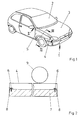
- FIG. 1 shows a motor vehicle with a front construction 1 and a windshield 2 adjoining the front construction 1.
- the front building 1 has a pivotably mounted hood 3.
- a trim 4 made of plastic is arranged on the side next to the hood 3.
- This panel 4 covers an underlying fender 5.
- the hood 3 and the panel 4 are in the vertical direction yieldingly designed and absorb impact energy generated in a pedestrian impact.
- FIG. 2 shows, in a longitudinal section through the front structure 1 of FIG. 1 along the line II - II, that the panel 4 is fastened to a body part 7 by means of two fastening elements 6 designed as screws.
- the fastening elements 6 are arranged exclusively at the ends of the panel 4.
- the panel 4 has for connection to the fastening elements 6 each have a mounting flange 8.
- the fasteners 6 are arranged outside of that area in which an impact of a head 9 of a pedestrian in an accident is to be expected.
- the head 9 of the pedestrian is shown schematically before an impact.
- Figure 3 shows in a sectional view of the front part 1 of the motor vehicle of Figure 1 along the line III - III, the diaphragm 4 and adjacent thereto areas of the hood 3 and the fender 5 in the ground state without load.
- an internal combustion engine 10 shown schematically in the drawing is arranged below the hood 3, an internal combustion engine 10 shown schematically in the drawing is arranged.
- the fender 5 has an upper, substantially horizontally disposed leg 11 and the outer skin of the motor vehicle forming lateral leg 12.
- the lateral leg 12 is substantially vertical.
- the horizontal leg 11 has at its side facing away from the lateral leg 12 a flange 13, with which it is attached to the body part 7.
- the body part 7 may be, for example, a side member.
- the legs 11, 12 of the fender 5 have at their adjoining areas a recess 14 into which an edge 15 of the aperture 4 penetrates.
- the end facing away from the recess 14 of the fender 5 has a vertically downwardly facing skirt 16th
- FIG. 4 The front structure 1 of Figure 3 in a collision of the head 9 of a pedestrian on the hood 3 near the panel 4 is shown in Figure 4.
- the internal combustion engine 10 has a distance to the underside of the hood 3, so that the hood 3 can move or deform in the vertical direction in an impact of the head 9 of the pedestrian downwards without being supported by the internal combustion engine 10 become.
- the diaphragm 4 deforms. In this case, the edge 15 of the diaphragm 4, which is held in the base state in the recess 14 of the fender 5, comes out of the recess 14. The diaphragm 4 moves toward the fender 5 as it is deformed.
- the kinetic energy of the head 9 is reduced according to the stiffness of the diaphragm 4 and the resilience of the hood 3 and thus the movement of the head 9 is delayed.
- To illustrate the unloaded ground state of the front structure 1 is shown in phantom in the drawing.
Landscapes
- Engineering & Computer Science (AREA)
- Mechanical Engineering (AREA)
- Superstructure Of Vehicle (AREA)
- Body Structure For Vehicles (AREA)
- Motor Or Generator Cooling System (AREA)
- Arrangement Or Mounting Of Propulsion Units For Vehicles (AREA)
Abstract
Description
- Die Erfindung betrifft einen Vorderbau einer Karosserie für ein Kraftfahrzeug mit einem in der vorgesehenen Fahrtrichtung gesehen vorderen Kotflügel, mit einem Karosserieteil zur Halterung des Kotflügels und mit einer an den Kotflügel angrenzenden, in vertikaler Richtung nachgiebig ausgebildeten Haube.
- Vorderbauten von Kraftfahrzeugen, bei denen die Haube nachgiebig gestaltet ist, werden häufig zum Schutz von Fußgängern bei einem Kopfaufprall eingesetzt. Bei dem Aufprall des Fußgängers auf die Haube gibt diese nach und vermindert damit die auf den Kopf einwirkende Belastung. Die Nachgiebigkeit der Hauben, welche maßgeblich für vorgesehene Verzögerungswerte beim Aufprall des Kopfes des Fußgängers ist, wird beispielsweise durch entsprechende, leicht verformbare Haubenscharniere oder durch eine entsprechende konstruktive Gestaltung der Haube erreicht. Weiterhin weist die Haube einen Abstand zu einer unterhalb der Haube angeordneten Brennkraftmaschine auf. Bei einem Aufprall des Fußgängers in dem Bereich der Haube nahe an dem Kotflügel besteht jedoch die Gefahr der Verletzung an dem Kotflügel.
- Daher ist aus der DE 29 34 060 A1 bereits ein Vorderbau bekannt, bei dem die Haube und die diese umrahmenden Karosserieteile, wie beispielsweise die Kotflügel, über bleibend verformare Deformationsglieder an Versteifungsstellen der Karosserie abgestützt sind. Die konkrete Ausführung dieses Vorderbaus besteht aus einem halbkreisförmig gebogenen Blech zwischen der inneren Kante der Außenhaut des Kotflügels und dem darunter liegenden Karosserieteil. Dasselbe gilt für die dem Kotflügel gegenüberliegende Kante der Fronthaube. Schlägt der Kopf eines Fußgängers in diesem Bereich auf, nehmen die Deformationsglieder die Stoßenergie auf, wodurch der Kopfaufprall relativ weich erfolgen soll.
- Nachteilig bei dem bekannten Vorderbau ist jedoch, dass sich die Deformationsglieder nur sehr schwierig für die Fälle eines Aufpralls des Kopfes ausschließlich auf die Haube oder eines Aufpralls auf die Haube nahe des Kotflügels auf die vorgesehene Nachgiebigkeit einstellen lassen. Dies führt insbesondere bei einem Kopfaufprall auf die Haube nahe des meist sehr schmalen Kotflügels dazu, dass beim Niederdrücken der Haube eine daran angrenzende Kante des Kotflügels stehen bleibt und Ursache für Kopfverletzungen sein kann.
- Weiterhin ist ein solcher Vorderbau aus der WO 01/28821 A1 bekannt. Bei diesem Vorderbau ist die Haube ebenfalls in vertikaler Richtung nachgiebig gehalten. Die Anbindung des Kotflügels an das Karosserieteil weist einen von dem Karosserieteil bis zu dem Kotflügel schräg nach außen verlaufenden Halter auf. Hierdurch ragt ein inneres Ende des Kotflügels in Richtung auf die Fronthaube frei über den Halter hinaus und kann daher bei einem Kopfaufprall leicht nachgeben. Alternativ ist aus der WO 01/28821 A1 bekannt, den Halter mit einer Rampe auszustatten, welche in der Bewegungsbahn der Haube bei einem Kopfaufprall befindet. Bei einem Kopfaufprall gleitet die Haube an der Rampe entlang und drückt den Kotflügel nach außen. Hierdurch wird das Verletzungsrisiko eines Fußgängers bei einem Kopfaufprall auf die Haube, insbesondere im an den Kotflügel angrenzenden Bereich im Vergleich zu einer steifen Anbindung des Kotflügels an das Karosserieteil gering gehalten. Jedoch erfordert der Kotflügel zur Abstützung von Betriebskräften eine ausreichende Eigensteifigkeit, wodurch die Verzögerung beim Kopfaufprall begrenzt ist. Die vorgesehene Einstellung der Steifheit des Halteteils und des Kotflügels gestaltet sich daher sehr aufwändig.
- Der Erfindung liegt das Problem zugrunde, einen Vorderbau der eingangs genannten Art so weiterzubilden, dass vorgesehene Verzögerungswerte bei einem Kopfaufprall weiter verbessert werden und mit besonders geringem Aufwand einfach einstellbar sind.
- Dieses Problem wird erfindungsgemäß dadurch gelöst, dass eine Blende zwischen dem Kotflügel und der Haube angeordnet ist und dass die Blende nachgiebig gestaltet ist.
- Durch diese Gestaltung grenzt die von dem Kotflügel getrennte Blende an die Haube an. Die Blende lässt sich im Gegensatz zu dem Kotflügel mit einer wesentlich geringeren Steifheit fertigen, da an dem unmittelbar an die Haube angrenzenden Bereich des Vorderbaus nur geringe Betriebskräfte abzustützen sind. Die Blende lässt sich damit als Dämpfungskörper ausbilden, so dass ein Kopfaufprall gedämpft wird. Hierdurch lassen sich die vorgesehenen geringen Verzögerungswerte mit besonders geringem konstruktiven Aufwand einfach einstellen.
- Der erfindungsgemäße Vorderbau gestaltet sich konstruktiv besonders einfach, wenn ein oberer Schenkel des Kotflügels tiefer angeordnet ist als die Oberkante der Haube und wenn die Blende oberhalb des oberen Schenkels des Kotflügels angeordnet ist. Durch diese Gestaltung lässt sich der gesamte Raum zwischen der Oberseite der Blende und dem oberen Schenkel des Kotflügels zum Abbau der Aufprallenergie beim Kopfaufprall nutzen. Der Abbau der Aufprallenergie durch die Blende erfolgt unabhängig von der Stabilität des Kotflügels, da der obere Schenkel die Oberkante des Kotflügels darstellt und ein auf den Vorderbau aufprallender Fußgänger ausschließlich in Kontakt mit der Haube oder der Blende gelangen kann. Zudem wird durch diese Gestaltung vermieden, dass beim Niederdrücken der Haube eine scharfe Kante des Kotflügels in dem Aufprallbereich hervorsteht. Dank der Erfindung hat der Kotflügel in seinem an die Haube angrenzenden Bereich keine Abkantung.
- Zur weiteren Verringerung der Verletzungsgefahr beim Fußgängeraufprall trägt es gemäß einer anderen vorteilhaften Weiterbildung der Erfindung bei, wenn die Blende aus Kunststoff gefertigt ist. Eine solche Fertigung der Blende ermöglicht bei besonders geringen Herstellungskosten eine besonders einfache Einstellbarkeit der Steifheit der Blende. Zudem ermöglicht die Fertigung der Blende aus Kunststoff eine große Deformation unter statischen Lasten, beispielsweise beim Aufstützen auf die Blende, ohne jedoch bleibende plastische Verformungen hervorzurufen. Im einfachsten Fall ist die Blende aufgebaut, wie es von aus Kunststoff gefertigten Stoßfängern heutiger Kraftfahrzeuge bekannt ist. Beispielsweise kann die Blende eine Schaumstofffüllung oder eine gitterartige Unterstruktur aufweisen und zumindest teilweise kostengünstig im Spritzgussverfahren gefertigt werden.
- Die Blende könnte beispielsweise an der Haube befestigt werden. Eine Verformung der Blende unabhängig von der Haube lässt sich jedoch gemäß einer anderen vorteilhaften Weiterbildung der Erfindung erzeugen, wenn die Blende an einem feststehenden Bauteil der Karosserie befestigt ist. Vorzugsweise wird die Blende an dem Kotflügel oder dem Längsträger befestigt.
- Befestigungselemente zur Befestigung der Blende an den übrigen Bauteilen des erfindungsgemäßen Vorderbaus können zu einer Versteifung der Blende und damit zu einer Erhöhung des Verletzungsrisikos bei einem Kopfaufprall führen. Zur weiteren Verminderung des Verletzungsrisikos bei einem Kopfaufprall trägt es gemäß einer anderen vorteilhaften Weiterbildung der Erfindung bei, wenn die Blende langgestreckt ausgebildet ist und wenn Befestigungselemente zur Anbindung der Blende an angrenzenden Bereichen der Karosserie außerhalb eines für einen Kopfaufprall eines Fußgängers berechneten Bereichs angeordnet sind. Daher führt eine Versteifung der Blende durch die Befestigungselemente nicht zu einer Erhöhung der Verletzungsgefahr. Vorzugsweise sind die Befestigungselemente an den Enden der Blende angeordnet.
- Zur weiteren Vergrößerung des von der Blende einnehmbaren Verformungsraumes trägt es gemäß einer anderen vorteilhaften Weiterbildung der Erfindung bei, wenn der obere Schenkel des Kotflügels einen im Wesentlichen horizontalen Abschnitt aufweist.
- Die Montage des erfindungsgemäßen Vorderbaus gestaltet sich konstruktiv besonders einfach, wenn der obere Schenkel des Kotflügels einen Flansch aufweist, mit dem er an einem Karosserieteil der Karosserie befestigt ist. Durch diese Gestaltung kann zudem auf die Anordnung eines Wasserkanals an der Befestigung des Kotflügels verzichtet werden. Vorzugsweise ist das Karosserieteil zur Halterung des Kotflügels ein Längsträger.
- Die Blende vermag gemäß einer anderen vorteilhaften Weiterbildung der Erfindung im Normalbetrieb des Kraftfahrzeuges auftretende Betriebskräfte abzustützen, ohne dabei aus ihrer Position heraus bewegt zu werden, wenn der Kotflügel in einem aneinander stoßenden Abschnitt des oberen Schenkels und einem die Außenhaut der Karosserie bildenden äußeren seitlichen Schenkel eine Vertiefung zur Aufnahme eines Randes der Blende hat.
- Zur weiteren Verringerung der Verletzungsgefahr beim Kopfaufprall trägt es jedoch gemäß einer anderen vorteilhaften Weiterbildung der Erfindung bei, wenn die Blende eine von der Haube aus gesehen bis zu der Vertiefung des Kotflügels abfallende Kontur hat. Die Blende wird im Normalbetrieb des Kraftfahrzeuges in der Vertiefung abgestützt oder beispielsweise durch Fahrtwind mit ihrem Rand in die Vertiefung hineingedrückt. Bei einem Kopfaufprall kann jedoch, bedingt durch die Kontur der Blende, der in der Vertiefung angeordnete Rand der Blende aus der Vertiefung herausgleiten. Anschließend kann die Aufprallenergie durch das Material und die Form der Blende abgebaut werden.
- Ein Hervorstehen einer scharfen Kante der Blende beim Niederdrücken der Haube lässt sich gemäß einer anderen vorteilhaften Weiterbildung der Erfindung einfach vermeiden, wenn die Blende an ihrem an die Haube angrenzenden Bereich eine in Bewegungsrichtung der Haube bei einem Kopfaufprall weisende Schürze hat.
- Die Erfindung lässt verschiedene Ausführungsformen zu. Zur weiteren Verdeutlichung ihres Grundprinzips ist eine davon in der Zeichnung dargestellt und wird nachfolgend beschrieben. Die Zeichnung zeigt in
- Fig. 1
- eine perspektivische Darstellung eines Kraftfahrzeuges mit einem erfindungsgemäßen Vorderbau,
- Fig. 2
- schematisch eine Schnittdarstellung durch einen Teilbereich des erfindungsgemäßen Vorderbaus aus Figur 1 entlang der Linie II - II,
- Fig. 3
- schematisch eine Schnittdarstellung durch einen Teilbereich des erfindungsgemäßen Vorderbaus aus Figur 1 entlang der Linie III - III,
- Fig. 4
- der Teilbereich des erfindungsgemäßen Vorderbaus aus Figur 3 bei einem Kopfaufprall.
- Figur 1 zeigt ein Kraftfahrzeug mit einem Vorderbau 1 und einer sich an den Vorderbau 1 anschließende Frontscheibe 2. Der Vorderbau 1 hat eine schwenkbar gelagerte Haube 3. Seitlich neben der Haube 3 ist eine Blende 4 aus Kunststoff angeordnet. Diese Blende 4 überdeckt einen darunter befindlichen Kotflügel 5. Die Haube 3 und die Blende 4 sind in vertikaler Richtung nachgiebig gestaltet und absorbieren bei einem Aufprall eines Fußgängers entstehende Aufprallenergie.
- Figur 2 zeigt in einer Schnittdarstellung in Längsrichtung durch den Vorderbau 1 aus Figur 1 entlang der Linie II - II, dass die Blende 4 mittels zweier als Schrauben ausgebildeter Befestigungselemente 6 an einem Karosserieteil 7 befestigt ist. Die Befestigungselemente 6 sind ausschließlich an den Enden der Blende 4 angeordnet. Die Blende 4 hat zur Verbindung mit den Befestigungselementen 6 jeweils einen Befestigungsflansch 8. Damit sind die Befestigungselemente 6 außerhalb desjenigen Bereichs angeordnet, in welchem ein Aufprall eines Kopfes 9 eines Fußgängers bei einem Unfall zu erwarten ist. In Figur 2 ist der Kopf 9 des Fußgängers vor einem Aufprall schematisch dargestellt.
- Figur 3 zeigt in einer Schnittdarstellung des Vorderbaus 1 des Kraftfahrzeuges aus Figur 1 entlang der Linie III - III die Blende 4 und daran angrenzende Bereiche der Haube 3 und des Kotflügels 5 im Grundzustand ohne Belastung. Unterhalb der Haube 3 ist eine in der Zeichnung schematisch dargestellte Brennkraftmaschine 10 angeordnet. Der Kotflügel 5 weist einen oberen, im Wesentlichen horizontal angeordneten Schenkel 11 und einen die Außenhaut des Kraftfahrzeuges bildenden seitlichen Schenkel 12 auf. Der seitliche Schenkel 12 verläuft im Wesentlichen vertikal. Der horizontale Schenkel 11 weist an seinem dem seitlichen Schenkel 12 abgewandten Ende einen Flansch 13 auf, mit dem er an dem Karosserieteil 7 befestigt ist. Bei dem Karosserieteil 7 kann es sich beispielsweise um einen Längsträger handeln. Die Schenkel 11, 12 des Kotflügels 5 weisen an ihren aneinandergrenzenden Bereichen eine Vertiefung 14 auf, in die ein Rand 15 der Blende 4 eindringt. Das von der Vertiefung 14 abgewandte Ende des Kotflügels 5 hat eine vertikal nach unten weisende Schürze 16.
- Der Vorderbau 1 aus Figur 3 bei einem Aufprall des Kopfes 9 eines Fußgängers auf die Haube 3 nahe der Blende 4 ist in Figur 4 dargestellt. Deutlich ist zu erkennen, dass die Brennkraftmaschine 10 einen Abstand zu der Unterseite der Haube 3 hat, so dass sich die Haube 3 bei einem Aufprall des Kopfes 9 des Fußgängers in vertikaler Richtung nach unten bewegen oder verformen kann, ohne von der Brennkraftmaschine 10 abgestützt zu werden. Weiterhin verformt sich die Blende 4. Dabei gelangt der im Grundzustand in der Vertiefung 14 des Kotflügels 5 gehaltene Rand 15 der Blende 4 aus der Vertiefung 14 heraus. Die Blende 4 bewegt sich bei ihrer Verformung auf den Kotflügel 5 zu. Hierbei wird die Bewegungsenergie des Kopfes 9 entsprechend der Steifheit der Blende 4 und der Nachgiebigkeit der Haube 3 abgebaut und damit die Bewegung des Kopfes 9 verzögert. Zur Verdeutlichung ist in der Zeichnung der unbelastete Grundzustand des Vorderbaus 1 strichpunktiert dargestellt.
-
- 1
- Vorderbau
- 2
- Frontscheibe
- 3
- Haube
- 4
- Blende
- 5
- Kotflügel
- 6
- Befestigungselement
- 7
- Karosserieteil
- 8
- Befestigungsflansch
- 9
- Kopf
- 10
- Brennkraftmaschine
- 11, 12
- Schenkel
- 13
- Flansch
- 14
- Vertiefung
- 15
- Rand
- 16
- Schürze
Claims (11)
- Vorderbau (1) einer Karosserie für ein Kraftfahrzeug mit einem in der vorgesehenen Fahrtrichtung gesehen vorderen Kotflügel (5), mit einem Karosserieteil (7) zur Halterung des Kotflügels (5) und mit einer an den Kotflügel (5) angrenzenden, in vertikaler Richtung nachgiebig ausgebildeten Haube (3), dadurch gekennzeichnet, dass eine Blende (4) zwischen dem Kotflügel (5) und der Haube (3) angeordnet ist und dass die Blende (4) nachgiebig gestaltet ist.
- Vorderbau nach Anspruch 1, dadurch gekennzeichnet, dass ein oberer Schenkel (11) des Kotflügels (5) tiefer angeordnet ist als die Oberkante der Haube (3) und dass die Blende (4) oberhalb des oberen Schenkels (11) des Kotflügels (5) angeordnet ist.
- Vorderbau nach Anspruch 1 oder 2, dadurch gekennzeichnet, dass die Blende (4) aus Kunststoff gefertigt ist.
- Vorderbau nach zumindest einem der vorhergehenden Ansprüche, dadurch gekennzeichnet, dass die Blende (4) an einem feststehenden Bauteil der Karosserie befestigt ist.
- Vorderbau nach zumindest einem der vorhergehenden Ansprüche, dadurch gekennzeichnet, dass die Blende (4) langgestreckt ausgebildet ist und dass Befestigungselemente (6) zur Anbindung der Blende (4) an angrenzenden Bereichen der Karosserie außerhalb eines für einen Kopfaufprall eines Fußgängers berechneten Bereichs angeordnet sind.
- Vorderbau nach zumindest einem der vorhergehenden Ansprüche, dadurch gekennzeichnet, dass die Befestigungselemente (6) an den Enden der Blende (4) angeordnet sind.
- Vorderbau nach zumindest einem der vorhergehenden Ansprüche, dadurch gekennzeichnet, dass der obere Schenkel (11) des Kotflügels (5) einen im Wesentlichen horizontalen Abschnitt aufweist.
- Vorderbau nach zumindest einem der vorhergehenden Ansprüche, dadurch gekennzeichnet, dass der obere Schenkel (11) des Kotflügels (5) einen Flansch (13) aufweist, mit dem er an einem Karosserieteil (7) der Karosserie befestigt ist.
- Vorderbau nach zumindest einem der vorhergehenden Ansprüche, dadurch gekennzeichnet, dass der Kotflügel (5) in einem aneinander stoßenden Abschnitt des oberen Schenkels (11) und einem die Außenhaut der Karosserie bildenden äußeren, seitlichen Schenkel (12) eine Vertiefung (14) zur Aufnahme eines Randes (15) der Blende (4) hat.
- Vorderbau nach zumindest einem der vorhergehenden Ansprüche, dadurch gekennzeichnet, dass die Blende (4) eine von der Haube (3) aus gesehen bis zu der Vertiefung (14) des Kotflügels (5) abfallende Kontur hat.
- Vorderbau nach zumindest einem der vorhergehenden Ansprüche, dadurch gekennzeichnet, dass die Blende (4) an ihrem an die Haube (3) angrenzenden Bereich eine in Bewegungsrichtung der Haube (3) bei einem Kopfaufprall weisende Schürze (16) hat.
Applications Claiming Priority (1)
| Application Number | Priority Date | Filing Date | Title |
|---|---|---|---|
| DE102004035422A DE102004035422A1 (de) | 2004-07-21 | 2004-07-21 | Vorderbau einer Karosserie für ein Kraftfahrzeug |
Publications (2)
| Publication Number | Publication Date |
|---|---|
| EP1619088A1 true EP1619088A1 (de) | 2006-01-25 |
| EP1619088B1 EP1619088B1 (de) | 2008-10-15 |
Family
ID=34982538
Family Applications (1)
| Application Number | Title | Priority Date | Filing Date |
|---|---|---|---|
| EP05015712A Expired - Lifetime EP1619088B1 (de) | 2004-07-21 | 2005-07-20 | Vorderbau einer Karosserie für ein Kraftfahrzeug |
Country Status (3)
| Country | Link |
|---|---|
| EP (1) | EP1619088B1 (de) |
| AT (1) | ATE411204T1 (de) |
| DE (2) | DE102004035422A1 (de) |
Cited By (2)
| Publication number | Priority date | Publication date | Assignee | Title |
|---|---|---|---|---|
| US7690722B2 (en) | 2007-05-21 | 2010-04-06 | Honda Motor Co., Ltd. | Energy absorbing vehicle hood stopper assembly |
| US9033399B2 (en) | 2010-03-01 | 2015-05-19 | Sabic Global Technologies B.V. | Energy absorber elements and vehicle systems |
Citations (5)
| Publication number | Priority date | Publication date | Assignee | Title |
|---|---|---|---|---|
| DE2934060A1 (de) | 1979-08-23 | 1981-03-26 | Daimler-Benz Aktiengesellschaft, 70567 Stuttgart | Kraftfahrzeug, insbesondere personenkraftwagen, mit nachgiebigen karosseriefrontteilen |
| JP2000108840A (ja) * | 1998-09-30 | 2000-04-18 | Mazda Motor Corp | 車両用前部構造 |
| DE19853340A1 (de) * | 1998-11-19 | 2000-05-25 | Volkswagen Ag | Sicherheitseinrichtung als Fußgängeraufprallschutz am Vorderwagen eines Kraftfahrzeugs |
| WO2001028821A1 (de) | 1999-10-19 | 2001-04-26 | Adam Opel Ag | Vorderbau für ein kraftfahrzeug |
| JP2002046650A (ja) * | 2000-08-02 | 2002-02-12 | Mazda Motor Corp | 車両前部の構造 |
Family Cites Families (11)
| Publication number | Priority date | Publication date | Assignee | Title |
|---|---|---|---|---|
| JP3498514B2 (ja) * | 1997-02-06 | 2004-02-16 | 三菱自動車工業株式会社 | 自動車車体の前部構造 |
| DE19851472A1 (de) * | 1998-11-09 | 2000-05-11 | Volkswagen Ag | Karosseriehaube, insbesondere Fronthaube eines Kraftfahrzeugs |
| DE19948732A1 (de) * | 1999-10-09 | 2001-04-12 | Volkswagen Ag | Fußgängerfreundlich ausgelegtes Kraftfahrzeug-Frontend |
| DE19950294A1 (de) * | 1999-10-19 | 2001-04-26 | Opel Adam Ag | Vorderbau eines Fahrzeuges |
| DE10009364A1 (de) * | 2000-02-29 | 2001-08-30 | Volkswagen Ag | Kotflügelanordnung für ein Kraftfahrzeug |
| DE10063582A1 (de) * | 2000-12-20 | 2002-06-27 | Volkswagen Ag | Aufpralldämpfendes Karosserieteil für ein Fahrzeug |
| DE10102187A1 (de) * | 2001-01-16 | 2002-08-01 | Volkswagen Ag | Aufpralldämpfender Kotflügel für ein Fahrzeug |
| DE10126195C1 (de) * | 2001-05-30 | 2002-11-14 | Daimler Chrysler Ag | Fronthaubenanordnung für einen Personenkraftwagen |
| JP4192452B2 (ja) * | 2001-09-18 | 2008-12-10 | トヨタ自動車株式会社 | 車両のフェンダ構造 |
| DE10232799B4 (de) * | 2002-07-19 | 2016-10-27 | Volkswagen Ag | Vorbaustruktur an Kraftfahrzeugen |
| DE10233474B4 (de) * | 2002-07-24 | 2014-05-08 | Volkswagen Ag | Kotflügel an Kraftfahrzeugen |
-
2004
- 2004-07-21 DE DE102004035422A patent/DE102004035422A1/de not_active Withdrawn
-
2005
- 2005-07-20 AT AT05015712T patent/ATE411204T1/de not_active IP Right Cessation
- 2005-07-20 EP EP05015712A patent/EP1619088B1/de not_active Expired - Lifetime
- 2005-07-20 DE DE502005005673T patent/DE502005005673D1/de not_active Expired - Lifetime
Patent Citations (5)
| Publication number | Priority date | Publication date | Assignee | Title |
|---|---|---|---|---|
| DE2934060A1 (de) | 1979-08-23 | 1981-03-26 | Daimler-Benz Aktiengesellschaft, 70567 Stuttgart | Kraftfahrzeug, insbesondere personenkraftwagen, mit nachgiebigen karosseriefrontteilen |
| JP2000108840A (ja) * | 1998-09-30 | 2000-04-18 | Mazda Motor Corp | 車両用前部構造 |
| DE19853340A1 (de) * | 1998-11-19 | 2000-05-25 | Volkswagen Ag | Sicherheitseinrichtung als Fußgängeraufprallschutz am Vorderwagen eines Kraftfahrzeugs |
| WO2001028821A1 (de) | 1999-10-19 | 2001-04-26 | Adam Opel Ag | Vorderbau für ein kraftfahrzeug |
| JP2002046650A (ja) * | 2000-08-02 | 2002-02-12 | Mazda Motor Corp | 車両前部の構造 |
Non-Patent Citations (2)
| Title |
|---|
| PATENT ABSTRACTS OF JAPAN vol. 2000, no. 07 29 September 2000 (2000-09-29) * |
| PATENT ABSTRACTS OF JAPAN vol. 2002, no. 06 4 June 2002 (2002-06-04) * |
Cited By (3)
| Publication number | Priority date | Publication date | Assignee | Title |
|---|---|---|---|---|
| US7690722B2 (en) | 2007-05-21 | 2010-04-06 | Honda Motor Co., Ltd. | Energy absorbing vehicle hood stopper assembly |
| US9033399B2 (en) | 2010-03-01 | 2015-05-19 | Sabic Global Technologies B.V. | Energy absorber elements and vehicle systems |
| US9821753B2 (en) | 2010-03-01 | 2017-11-21 | Sabic Global Technologies B.V. | Energy absorber elements and vehicle systems |
Also Published As
| Publication number | Publication date |
|---|---|
| EP1619088B1 (de) | 2008-10-15 |
| DE502005005673D1 (de) | 2008-11-27 |
| ATE411204T1 (de) | 2008-10-15 |
| DE102004035422A1 (de) | 2006-03-16 |
Similar Documents
| Publication | Publication Date | Title |
|---|---|---|
| EP0992418B1 (de) | Karosseriehaube, insbesondere Motorraumhaube eines Kraftfahrzeugs | |
| DE102005021895B4 (de) | Frontstossfängerverkleidung | |
| DE69707792T2 (de) | Instrumententafel mit Airbagabdeckung | |
| DE2934060A1 (de) | Kraftfahrzeug, insbesondere personenkraftwagen, mit nachgiebigen karosseriefrontteilen | |
| DE10126195C1 (de) | Fronthaubenanordnung für einen Personenkraftwagen | |
| DE10112424A1 (de) | Kraftwagenbug mit einer Stoßfängereinheit | |
| DE10304784A1 (de) | Stoßfängeranordnung für Fahrzeuge, insbesondere Kraftfahrzeuge | |
| DE102009017350B4 (de) | Fußgängerschutzeinrichtung an einem Kraftfahrzeug | |
| DE10102187A1 (de) | Aufpralldämpfender Kotflügel für ein Fahrzeug | |
| DE10123480B4 (de) | Aufpralldämpfende Fronthaube an einem Fahrzeug | |
| DE102005037151A1 (de) | Stoßfängeranordnung für ein Kraftfahrzeug | |
| DE102004007571A1 (de) | Vorderwagen für ein Fahrzeug, insbesondere für ein Kraftfahrzeug | |
| DE102016010366B4 (de) | Fahrzeug-vorderstruktur | |
| DE102012218128A1 (de) | Fahrzeugstruktur zur Aufprallminderung | |
| DE102004027169B4 (de) | Kraftfahrzeugfront mit Mitten-Abdeckung im Spoilerbereich zum verbesserten Kollisionsschutz von Fußgängern | |
| DE102016002215A1 (de) | Vorderwagen für ein Kraftfahrzeug mit einer Stoßfängerverkleidung | |
| DE10233474B4 (de) | Kotflügel an Kraftfahrzeugen | |
| EP1619088B1 (de) | Vorderbau einer Karosserie für ein Kraftfahrzeug | |
| DE102005056961B4 (de) | Motorraumverkleidung für einen Kraftwagen | |
| DE10347830B4 (de) | Anordnung einer Frontklappe an einem Fahrzeug | |
| DE10305652A1 (de) | Frontendbereich | |
| DE102006014381B4 (de) | Sicherheitsvorrichtung für Kraftfahrzeuge | |
| DE102018008274B3 (de) | Kraftfahrzeug mit Fußgängerairbag und Wasserkastenabdeckung dafür | |
| EP1733926B1 (de) | Vorderbau für ein Kraftfahrzeug | |
| DE102016013877A1 (de) | Stützanordnung für einen Stoßfänger eines Kraftwagens |
Legal Events
| Date | Code | Title | Description |
|---|---|---|---|
| PUAI | Public reference made under article 153(3) epc to a published international application that has entered the european phase |
Free format text: ORIGINAL CODE: 0009012 |
|
| AK | Designated contracting states |
Kind code of ref document: A1 Designated state(s): AT BE BG CH CY CZ DE DK EE ES FI FR GB GR HU IE IS IT LI LT LU LV MC NL PL PT RO SE SI SK TR |
|
| AX | Request for extension of the european patent |
Extension state: AL BA HR MK YU |
|
| AKX | Designation fees paid | ||
| 17P | Request for examination filed |
Effective date: 20060918 |
|
| RBV | Designated contracting states (corrected) |
Designated state(s): AT BE BG CH CY CZ DE DK EE ES FI FR GB GR HU IE IS IT LI LT LU LV MC NL PL PT RO SE SI SK TR |
|
| 17Q | First examination report despatched |
Effective date: 20061023 |
|
| 17Q | First examination report despatched |
Effective date: 20061023 |
|
| GRAP | Despatch of communication of intention to grant a patent |
Free format text: ORIGINAL CODE: EPIDOSNIGR1 |
|
| GRAS | Grant fee paid |
Free format text: ORIGINAL CODE: EPIDOSNIGR3 |
|
| GRAA | (expected) grant |
Free format text: ORIGINAL CODE: 0009210 |
|
| AK | Designated contracting states |
Kind code of ref document: B1 Designated state(s): AT BE BG CH CY CZ DE DK EE ES FI FR GB GR HU IE IS IT LI LT LU LV MC NL PL PT RO SE SI SK TR |
|
| REG | Reference to a national code |
Ref country code: CH Ref legal event code: EP Ref country code: GB Ref legal event code: FG4D Free format text: NOT ENGLISH |
|
| REG | Reference to a national code |
Ref country code: IE Ref legal event code: FG4D Free format text: LANGUAGE OF EP DOCUMENT: GERMAN |
|
| REF | Corresponds to: |
Ref document number: 502005005673 Country of ref document: DE Date of ref document: 20081127 Kind code of ref document: P |
|
| NLV1 | Nl: lapsed or annulled due to failure to fulfill the requirements of art. 29p and 29m of the patents act | ||
| REG | Reference to a national code |
Ref country code: GB Ref legal event code: 732E Free format text: REGISTERED BETWEEN 20090305 AND 20090311 |
|
| PG25 | Lapsed in a contracting state [announced via postgrant information from national office to epo] |
Ref country code: ES Free format text: LAPSE BECAUSE OF FAILURE TO SUBMIT A TRANSLATION OF THE DESCRIPTION OR TO PAY THE FEE WITHIN THE PRESCRIBED TIME-LIMIT Effective date: 20090126 Ref country code: BG Free format text: LAPSE BECAUSE OF FAILURE TO SUBMIT A TRANSLATION OF THE DESCRIPTION OR TO PAY THE FEE WITHIN THE PRESCRIBED TIME-LIMIT Effective date: 20090115 Ref country code: LT Free format text: LAPSE BECAUSE OF FAILURE TO SUBMIT A TRANSLATION OF THE DESCRIPTION OR TO PAY THE FEE WITHIN THE PRESCRIBED TIME-LIMIT Effective date: 20081015 |
|
| PG25 | Lapsed in a contracting state [announced via postgrant information from national office to epo] |
Ref country code: NL Free format text: LAPSE BECAUSE OF FAILURE TO SUBMIT A TRANSLATION OF THE DESCRIPTION OR TO PAY THE FEE WITHIN THE PRESCRIBED TIME-LIMIT Effective date: 20081015 Ref country code: SI Free format text: LAPSE BECAUSE OF FAILURE TO SUBMIT A TRANSLATION OF THE DESCRIPTION OR TO PAY THE FEE WITHIN THE PRESCRIBED TIME-LIMIT Effective date: 20081015 Ref country code: IS Free format text: LAPSE BECAUSE OF FAILURE TO SUBMIT A TRANSLATION OF THE DESCRIPTION OR TO PAY THE FEE WITHIN THE PRESCRIBED TIME-LIMIT Effective date: 20090215 Ref country code: FI Free format text: LAPSE BECAUSE OF FAILURE TO SUBMIT A TRANSLATION OF THE DESCRIPTION OR TO PAY THE FEE WITHIN THE PRESCRIBED TIME-LIMIT Effective date: 20081015 Ref country code: PL Free format text: LAPSE BECAUSE OF FAILURE TO SUBMIT A TRANSLATION OF THE DESCRIPTION OR TO PAY THE FEE WITHIN THE PRESCRIBED TIME-LIMIT Effective date: 20081015 Ref country code: PT Free format text: LAPSE BECAUSE OF FAILURE TO SUBMIT A TRANSLATION OF THE DESCRIPTION OR TO PAY THE FEE WITHIN THE PRESCRIBED TIME-LIMIT Effective date: 20090316 Ref country code: LV Free format text: LAPSE BECAUSE OF FAILURE TO SUBMIT A TRANSLATION OF THE DESCRIPTION OR TO PAY THE FEE WITHIN THE PRESCRIBED TIME-LIMIT Effective date: 20081015 |
|
| REG | Reference to a national code |
Ref country code: IE Ref legal event code: FD4D |
|
| PG25 | Lapsed in a contracting state [announced via postgrant information from national office to epo] |
Ref country code: RO Free format text: LAPSE BECAUSE OF FAILURE TO SUBMIT A TRANSLATION OF THE DESCRIPTION OR TO PAY THE FEE WITHIN THE PRESCRIBED TIME-LIMIT Effective date: 20081015 Ref country code: DK Free format text: LAPSE BECAUSE OF FAILURE TO SUBMIT A TRANSLATION OF THE DESCRIPTION OR TO PAY THE FEE WITHIN THE PRESCRIBED TIME-LIMIT Effective date: 20081015 Ref country code: EE Free format text: LAPSE BECAUSE OF FAILURE TO SUBMIT A TRANSLATION OF THE DESCRIPTION OR TO PAY THE FEE WITHIN THE PRESCRIBED TIME-LIMIT Effective date: 20081015 Ref country code: IE Free format text: LAPSE BECAUSE OF FAILURE TO SUBMIT A TRANSLATION OF THE DESCRIPTION OR TO PAY THE FEE WITHIN THE PRESCRIBED TIME-LIMIT Effective date: 20081015 |
|
| PLBE | No opposition filed within time limit |
Free format text: ORIGINAL CODE: 0009261 |
|
| STAA | Information on the status of an ep patent application or granted ep patent |
Free format text: STATUS: NO OPPOSITION FILED WITHIN TIME LIMIT |
|
| PG25 | Lapsed in a contracting state [announced via postgrant information from national office to epo] |
Ref country code: IT Free format text: LAPSE BECAUSE OF FAILURE TO SUBMIT A TRANSLATION OF THE DESCRIPTION OR TO PAY THE FEE WITHIN THE PRESCRIBED TIME-LIMIT Effective date: 20081015 Ref country code: CZ Free format text: LAPSE BECAUSE OF FAILURE TO SUBMIT A TRANSLATION OF THE DESCRIPTION OR TO PAY THE FEE WITHIN THE PRESCRIBED TIME-LIMIT Effective date: 20081015 Ref country code: SE Free format text: LAPSE BECAUSE OF FAILURE TO SUBMIT A TRANSLATION OF THE DESCRIPTION OR TO PAY THE FEE WITHIN THE PRESCRIBED TIME-LIMIT Effective date: 20090115 |
|
| 26N | No opposition filed |
Effective date: 20090716 |
|
| PG25 | Lapsed in a contracting state [announced via postgrant information from national office to epo] |
Ref country code: SK Free format text: LAPSE BECAUSE OF FAILURE TO SUBMIT A TRANSLATION OF THE DESCRIPTION OR TO PAY THE FEE WITHIN THE PRESCRIBED TIME-LIMIT Effective date: 20081015 |
|
| REG | Reference to a national code |
Ref country code: GB Ref legal event code: 732E Free format text: REGISTERED BETWEEN 20091029 AND 20091104 |
|
| REG | Reference to a national code |
Ref country code: GB Ref legal event code: 732E Free format text: REGISTERED BETWEEN 20091105 AND 20091111 |
|
| BERE | Be: lapsed |
Owner name: GM GLOBAL TECHNOLOGY OPERATIONS, INC. Effective date: 20090731 |
|
| PG25 | Lapsed in a contracting state [announced via postgrant information from national office to epo] |
Ref country code: MC Free format text: LAPSE BECAUSE OF NON-PAYMENT OF DUE FEES Effective date: 20090731 |
|
| REG | Reference to a national code |
Ref country code: CH Ref legal event code: PL |
|
| PG25 | Lapsed in a contracting state [announced via postgrant information from national office to epo] |
Ref country code: LI Free format text: LAPSE BECAUSE OF NON-PAYMENT OF DUE FEES Effective date: 20090731 Ref country code: CH Free format text: LAPSE BECAUSE OF NON-PAYMENT OF DUE FEES Effective date: 20090731 |
|
| PG25 | Lapsed in a contracting state [announced via postgrant information from national office to epo] |
Ref country code: BE Free format text: LAPSE BECAUSE OF NON-PAYMENT OF DUE FEES Effective date: 20090731 |
|
| PG25 | Lapsed in a contracting state [announced via postgrant information from national office to epo] |
Ref country code: GR Free format text: LAPSE BECAUSE OF FAILURE TO SUBMIT A TRANSLATION OF THE DESCRIPTION OR TO PAY THE FEE WITHIN THE PRESCRIBED TIME-LIMIT Effective date: 20090116 |
|
| PG25 | Lapsed in a contracting state [announced via postgrant information from national office to epo] |
Ref country code: AT Free format text: LAPSE BECAUSE OF NON-PAYMENT OF DUE FEES Effective date: 20090720 |
|
| PG25 | Lapsed in a contracting state [announced via postgrant information from national office to epo] |
Ref country code: LU Free format text: LAPSE BECAUSE OF NON-PAYMENT OF DUE FEES Effective date: 20090720 |
|
| REG | Reference to a national code |
Ref country code: DE Ref legal event code: R081 Ref document number: 502005005673 Country of ref document: DE Owner name: GM GLOBAL TECHNOLOGY OPERATIONS LLC (N. D. GES, US Free format text: FORMER OWNER: GM GLOBAL TECHNOLOGY OPERATIONS, INC., DETROIT, MICH., US Effective date: 20110323 Ref country code: DE Ref legal event code: R081 Ref document number: 502005005673 Country of ref document: DE Owner name: GM GLOBAL TECHNOLOGY OPERATIONS LLC (N. D. GES, US Free format text: FORMER OWNER: GM GLOBAL TECHNOLOGY OPERATIONS, INC., DETROIT, US Effective date: 20110323 |
|
| PG25 | Lapsed in a contracting state [announced via postgrant information from national office to epo] |
Ref country code: HU Free format text: LAPSE BECAUSE OF FAILURE TO SUBMIT A TRANSLATION OF THE DESCRIPTION OR TO PAY THE FEE WITHIN THE PRESCRIBED TIME-LIMIT Effective date: 20090416 |
|
| PG25 | Lapsed in a contracting state [announced via postgrant information from national office to epo] |
Ref country code: TR Free format text: LAPSE BECAUSE OF FAILURE TO SUBMIT A TRANSLATION OF THE DESCRIPTION OR TO PAY THE FEE WITHIN THE PRESCRIBED TIME-LIMIT Effective date: 20081015 |
|
| PG25 | Lapsed in a contracting state [announced via postgrant information from national office to epo] |
Ref country code: CY Free format text: LAPSE BECAUSE OF FAILURE TO SUBMIT A TRANSLATION OF THE DESCRIPTION OR TO PAY THE FEE WITHIN THE PRESCRIBED TIME-LIMIT Effective date: 20081015 |
|
| PGFP | Annual fee paid to national office [announced via postgrant information from national office to epo] |
Ref country code: DE Payment date: 20120718 Year of fee payment: 8 |
|
| PGFP | Annual fee paid to national office [announced via postgrant information from national office to epo] |
Ref country code: FR Payment date: 20130724 Year of fee payment: 9 Ref country code: GB Payment date: 20130717 Year of fee payment: 9 |
|
| REG | Reference to a national code |
Ref country code: DE Ref legal event code: R119 Ref document number: 502005005673 Country of ref document: DE Effective date: 20140201 |
|
| PG25 | Lapsed in a contracting state [announced via postgrant information from national office to epo] |
Ref country code: DE Free format text: LAPSE BECAUSE OF NON-PAYMENT OF DUE FEES Effective date: 20140201 |
|
| GBPC | Gb: european patent ceased through non-payment of renewal fee |
Effective date: 20140720 |
|
| REG | Reference to a national code |
Ref country code: FR Ref legal event code: ST Effective date: 20150331 |
|
| PG25 | Lapsed in a contracting state [announced via postgrant information from national office to epo] |
Ref country code: FR Free format text: LAPSE BECAUSE OF NON-PAYMENT OF DUE FEES Effective date: 20140731 Ref country code: GB Free format text: LAPSE BECAUSE OF NON-PAYMENT OF DUE FEES Effective date: 20140720 |