EP1617907B1 - Selbstanpassende fibrillationsinduktion - Google Patents
Selbstanpassende fibrillationsinduktion Download PDFInfo
- Publication number
- EP1617907B1 EP1617907B1 EP04760265A EP04760265A EP1617907B1 EP 1617907 B1 EP1617907 B1 EP 1617907B1 EP 04760265 A EP04760265 A EP 04760265A EP 04760265 A EP04760265 A EP 04760265A EP 1617907 B1 EP1617907 B1 EP 1617907B1
- Authority
- EP
- European Patent Office
- Prior art keywords
- fibrillation
- protocol
- defibrillator
- induction
- parameter value
- Prior art date
- Legal status (The legal status is an assumption and is not a legal conclusion. Google has not performed a legal analysis and makes no representation as to the accuracy of the status listed.)
- Expired - Lifetime
Links
Images



Classifications
-
- A—HUMAN NECESSITIES
- A61—MEDICAL OR VETERINARY SCIENCE; HYGIENE
- A61N—ELECTROTHERAPY; MAGNETOTHERAPY; RADIATION THERAPY; ULTRASOUND THERAPY
- A61N1/00—Electrotherapy; Circuits therefor
- A61N1/18—Applying electric currents by contact electrodes
- A61N1/32—Applying electric currents by contact electrodes alternating or intermittent currents
- A61N1/36—Applying electric currents by contact electrodes alternating or intermittent currents for stimulation
- A61N1/362—Heart stimulators
- A61N1/37—Monitoring; Protecting
- A61N1/371—Capture, i.e. successful stimulation
- A61N1/3712—Auto-capture, i.e. automatic adjustment of the stimulation threshold
-
- A—HUMAN NECESSITIES
- A61—MEDICAL OR VETERINARY SCIENCE; HYGIENE
- A61N—ELECTROTHERAPY; MAGNETOTHERAPY; RADIATION THERAPY; ULTRASOUND THERAPY
- A61N1/00—Electrotherapy; Circuits therefor
- A61N1/18—Applying electric currents by contact electrodes
- A61N1/32—Applying electric currents by contact electrodes alternating or intermittent currents
- A61N1/38—Applying electric currents by contact electrodes alternating or intermittent currents for producing shock effects
- A61N1/385—Devices for inducing an abnormal cardiac function, e.g. fibrillation
-
- A—HUMAN NECESSITIES
- A61—MEDICAL OR VETERINARY SCIENCE; HYGIENE
- A61N—ELECTROTHERAPY; MAGNETOTHERAPY; RADIATION THERAPY; ULTRASOUND THERAPY
- A61N1/00—Electrotherapy; Circuits therefor
- A61N1/18—Applying electric currents by contact electrodes
- A61N1/32—Applying electric currents by contact electrodes alternating or intermittent currents
- A61N1/38—Applying electric currents by contact electrodes alternating or intermittent currents for producing shock effects
- A61N1/39—Heart defibrillators
- A61N1/3925—Monitoring; Protecting
- A61N1/3937—Monitoring output parameters
- A61N1/3943—Monitoring output parameters for threshold determination
Definitions
- the invention relates to medical devices, and more particularly, to medical devices for defibrillating hearts.
- An implanted device such as a defibrillator, for example, detects ventricular fibrillation, and delivers one or more electrical pulses to stop the fibrillation and allow the heart to reestablish a normal sinus rhythm.
- implantable defibrillators deliver a first pulse at a first energy level upon detecting fibrillation and, if the fibrillation is not stopped, deliver additional pulses at increasing energy levels until the fibrillation is stopped or the programmed progression of pulses has been exhausted.
- a physician or clinician programs the defibrillator to execute an initial fibrillation detection algorithm, and programs an initial progression of defibrillation pulses to be delivered in response to a detected fibrillation.
- the clinician programs the defibrillator to induce the heart to fibrillate, so that the programmed detection algorithm and pulse progression can be tested.
- the defibrillator induces fibrillation by delivering a pulse during the period of vulnerability within a cardiac cycle, e.g., during or near the T-wave, delivering a high frequency pulse train, delivering direct current, or other known methods for inducing fibrillation.
- the clinician programs the parameters for the induction attempt, such as the timing, amplitude, or other characteristics of a T-wave shock. If the induction attempt fails, the clinician must program new parameters for another induction attempt. When an induction attempt succeeds, the defibrillator can fail to detect the fibrillation, or fail to stop the fibrillation. In such cases, the clinician must modify the detection algorithm or the pulse progression. The process repeats until successful fibrillation induction, detection, and defibrillation occur such that the effectiveness of the defibrillator is confirmed.
- the invention is directed to a medical device comprising: a memory to store information relating to a plurality of fibrillation induction protocols; and a processor to select one of the fibrillation induction protocols as a first induction protocol defined by a first set of parameters for inducing fibrillation and a value for a first parameter of the first fibrillation induction protocol based on the information, control a defibrillator to attempt to induce fibrillation of a heart according to the first selected first protocol and the first parameter value, determine whether fibrillation was induced according to the first selected protocol and the first parameter value, modify the first parameter value based on the determination, attempt to induce fibrillation of the heart according to the selected first protocol and modified first parameter value, determine whether fibrillation was induced according to the selected first protocol and modified first parameter values, and automatically select a second induction protocol different than the first protocol defined by a second set of parameters for inducing fibrillation; and a value for a second parameter of the second induction protocol in response to determining that fibr
- the invention is directed to a method for monitoring an implantable medical device, comprising: automatically selecting a first fibrillation induction protocol defined by a first set of parameters for inducing fibrillation and a value for a first parameter of the first fibrillation induction protocol; attempting to induce fibrillation of a heart according to the selected first protocol and the first parameter value; determining whether fibrillation was induced according to the selected first protocol and the selected first parameter value; automatically modifying the first parameter value based on the determination; attempting to induce fibrillation of the heart according to the selected first protocol and the modified first parameter value; determining whether fibrillation was induced according to the selected first protocol and the modified first parameter value; and automatically selecting a second induction protocol defined by a second set of parameters for inducing fibrillation different than the first protocol and a value for a second parameter of the second induction protocol in response to determining that fibrillation was not induced according to the first protocol.
- the invention is directed to techniques for automating portions of the process of inducing fibrillation to test a defibrillator.
- the invention is directed to a self-adapting fibrillation induction feature.
- One or both of a programming device and an implanted defibrillator can provide the self-adapting fibrillation induction feature.
- a user activates this defibrillator induction feature via the programming device, which communicates with the defibrillator.
- the user can activate the defibrillator induction feature by entering a single command via the programming device.
- a fibrillation induction protocol such as T-wave shock, high-frequency pulse-train, or direct current delivery, and values for parameters of the protocol are selected.
- the defibrillator attempts to induce fibrillation according to the selected protocol and parameter values. If fibrillation induction is unsuccessful, parameter values are modified and new protocols are selected until fibrillation is successfully induced. Unsuccessful induction can be defined either as lack of any arrhythmia inducement (maintains sinus rhythm), or induction of a less lethal ventricular tachycardia.
- a fibrillation detection algorithm is modified. Verification of correct defibrillator detection can be accomplished by the programmer using surface electrogram signals in conjunction with telemetered information from the defibrillator. If an induced fibrillation is detected, it is treated according to a defibrillation therapy progression.
- the therapy progression can include a first pulse that is a safety margin below the maximum output of the defibrillator, and a second pulse at maximum output. If the first pulse terminates the fibrillation, the test is satisfied and the defibrillator is programmed for permanent operation.
- the first pulse fails to terminate the fibrillation, a user can be prompted to change the configuration of the defibrillator or the values for parameters of defibrillation pulses. If the progression fails to terminate the fibrillation, a user is alerted so that the patient can be manually defibrillated. The alert may be provided by activating an alarm.
- the user can activate the defibrillator induction feature more than one time for a single patient, for example, to establish and then confirm the effectiveness of the defibrillator in detecting and treating fibrillation. For example, depending on the size of the safety margin or the magnitude of the first pulsed, the user may decide that it would be appropriate to have two successful terminations of ventricular fibrillation before deciding that the defibrillator is effective.
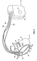
- FIG. 1 is a conceptual diagram illustrating an example system 10 that includes an implanted defibrillator 12 and a programming device 30.
- system 10 provides a self-adapting defibrillator induction feature.
- a user such as a physician or clinician, uses the self-adapting defibrillator induction feature to test the effectiveness of defibrillator 12 in treating fibrillations of a heart 14 of a patient 16.
- the self-adapting defibrillator induction feature can simplify the process of testing the effectiveness of defibrillator 12 from the perspective of the user.
- defibrillator 12 takes the form of a multi-chamber cardiac pacemaker-cardioverter-defibrillator (PCD) implanted within patient 16.
- Defibrillator 12 includes leads 18A, 18B and 18C (collectively "leads 18") that extend into the heart 14 of patient 16. More particularly, right ventricular (RV) lead 18A extends through one or more veins (not shown), the superior vena cava, and right atrium 26, and into right ventricle 20.
- Left ventricular (LV) coronary sinus lead 18B extends through the veins, the vena cava, right atrium 26, and into the coronary sinus 22 to a point adjacent to the free wall of left ventricle 24 of heart 14.
- Right atrial (RA) lead 18C extends through the veins and vena cava, and into the right atrium 26 of heart 14.
- Each of leads 18 includes electrodes (not shown), which defibrillator 12 uses to sense electrical signals attendant to the depolarization and repolarization of heart 14. In some embodiments, defibrillator 12 uses these electrodes to provide pacing pulses to heart 14.
- the electrodes used by defibrillator 12 for sensing and pacing can be unipolar or bipolar, as is well known in the art.
- Defibrillator 12 also provides defibrillation therapy, and in some embodiments provides cardioversion therapy, via electrodes located on leads 14. In some embodiments, electrodes used for defibrillation can also be used for sensing electrical activity of heart 14. Defibrillator 12 detects fibrillation of heart 14, such as fibrillation of ventricles 20 and 24, and delivers defibrillation therapy to heart 14 in the form of electrical pulses. Defibrillator 12 can be programmed to deliver a progression of therapies, e.g., pulses with increasing energy levels, until a fibrillation of heart 14 is stopped. Defibrillator 12 detects fibrillation employing one or more fibrillation detection techniques known in the art.
- Defibrillator 12 induces fibrillation of heart 14, e.g., ventricular fibrillation, to test the effectiveness of defibrillator 12 in detecting and stopping the fibrillation.
- Defibrillator 12 induces fibrillation according to a fibrillation induction protocol, and is capable of employing a plurality of fibrillation protocols to induce fibrillation.
- Exemplary fibrillation induction protocols include delivery of an electrical pulse to heart 14 during the T-wave of a cardiac cycle, delivery of a high-frequency pulse train, and delivery of direct current.
- the invention is not limited to the exemplary induction protocols, and defibrillator 12 can induce fibrillation according to any of a number of fibrillation induction protocols known in the art.
- the user uses programming device 30 to program defibrillator 12.
- the user for example, uses programming device 30 to program a therapy progression, select electrodes used to deliver defibrillation pulses, select waveforms for the defibrillation pulse, select a fibrillation detection algorithm, and the like for the permanent operation of defibrillator 12.
- the user can also use programming device 30 to program aspects of other therapies provided by defibrillator 12, such as cardioversion or defibrillation therapies.
- the user activates the self-adapting defibrillator induction feature provided by system 10 via programming device 30 to test the effectiveness of defibrillator 12 in detecting and treating fibrillation of heart 14.
- programming device 30 selects an induction protocol and values of parameters for the induction protocol, and defibrillator 12 attempts to induce fibrillation according to the selected protocol and parameter values.
- the parameter values are modified or a new protocol is selected without user intervention.
- the user interacts with programming device 30 and defibrillator 12 via a user interface.
- the user interface is provided via a keyboard 32 and a monitor 34, which may for example, be a CRT monitor, LCD monitor, LED monitor, or the like.
- Programming device 30 can additionally or alternatively include a pointing device, such as a mouse, via which a user interacts with the user interface.
- Programming device 30 communicates with defibrillator 12 via a programming head (not shown) placed over defibrillator 12, and telemetry circuits of defibrillator 12 as is known in the art.
- the user activates the self-adapting defibrillator induction feature by entering a single command via programming device 30, such as depression of a single key or combination of keys of keyboard 32 or a single point-and-select action with a pointing device.
- defibrillator 12 can include any number of leads 18, and each of leads 18 can extend to any location within or proximate to heart 14.
- some embodiments of defibrillator 12 include a single lead 18A or 18C that extends into right ventricle 20 or right atrium 26, respectively, or two leads 18A and 18C that extend into the right ventricle 20 and right atrium 26, respectively.
- Other embodiments of defibrillator 12 include leads 18A-C located as illustrated in FIG. 1, and an additional lead 18 located within or proximate to left atrium 28.
- defibrillator 12 need not be implanted within patient 16. Where defibrillator 12 is not implanted in patient 16, defibrillator 12 can deliver defibrillation pulses and other therapies to heart 14 via percutaneous leads that extend through the skin of patient 16 to a variety of positions within or outside of heart 14.
- FIG. 2 is a conceptual diagram illustrating defibrillator 12 in greater detail.
- leads 18 includes an elongated insulative lead body carrying a number of concentric coiled conductors separated from one another by tubular insulative sheaths.
- bipolar electrodes 40 and 42, 44 and 46, and 48 and 50 Located adjacent distal end of leads 18A, 18B and 18C are bipolar electrodes 40 and 42, 44 and 46, and 48 and 50 respectively. Electrodes 40, 44 and 48 can take the form of ring electrodes, and electrodes 42, 46 and 50 can take the form of extendable helix tip electrodes mounted retractably within insulative electrode heads 52, 54 and 56, respectively.
- Each of the electrodes 40-50 is coupled to one of the coiled conductors within the lead body of its associated lead 18.
- Sense/pace electrodes 40, 42, 44, 46, 48 and 50 sense electrical signals attendant to the depolarization and repolarization of heart 14. The electrical signals are conducted to defibrillator 12 via leads 18. In some embodiments, defibrillator 12 also delivers pacing pulses via sense/pace electrodes 40, 42, 44, 46, 48 and 50 to cause depolarization of cardiac tissue. Defibrillator 12 may also include one or more indifferent housing electrodes, such as housing electrode 58, formed integrally with an outer surface of the hermetically sealed housing 60 of defibrillator 12. Any of electrodes 40, 42, 44, 46, 48 and 50 can be used for unipolar sensing or pacing in combination with housing electrode 58.
- Leads 18A, 18B and 18C also, as shown in FIG. 2, include elongated coil electrodes 62, 64 and 66, respectively.
- IMD 10 delivers defibrillation pulses to heart 14 via any combination of defibrillation electrodes 62-66, which can also be combined with housing electrode 58. Electrodes 58 and 62-66 can also be used to deliver cardioversion pulses to heart 14.
- Defibrillation electrodes 62-66 are fabricated from platinum, platinum alloy or other materials known to be usable in implantable defibrillation electrodes, and may be about 5 cm in length.
- FIG. 3 is a functional block diagram of defibrillator 12.
- defibrillator 12 can take the form of a multi-chamber PCD having a microprocessor-based architecture.
- this diagram should be taken as exemplary of the type of device in which various embodiments of the present invention may be embodied, and not as limiting.
- Defibrillator 12 includes a microprocessor 70.
- Microprocessor 70 executes program instructions stored in memory, such as a ROM (not shown), EEPROM (not shown), and/or RAM 72, which control microprocessor 70 to perform the functions ascribed to microprocessor 70 herein.
- Microprocessor 70 is coupled to, e.g., to communicate with and/or control, various other components of defibrillator 12 via an address/data bus 74.
- Defibrillator 12 senses electrical activity within heart 14. Electrodes 40 and 42 are coupled to amplifier 76, which can take the form of an automatic gain controlled amplifier providing an adjustable sensing threshold as a function of the measured R-wave amplitude. A signal is generated on RV out line 78 whenever the signal sensed between electrodes 40 and 42 exceeds the present sensing threshold. Thus, electrodes 40 and 42 and amplifier 76 are used to detect intrinsic right ventricular depolarizations.
- Electrodes 44 and 46 are coupled to amplifier 80, which also can take the form of an automatic gain controlled amplifier providing an adjustable sensing threshold as a function of measured R-wave amplitude. A signal is generated on LV out line 82 whenever the signal sensed between electrodes 44 and 46 exceeds the present sensing threshold. Thus, electrodes 44 and 46 and amplifier 80 are used to detect intrinsic left ventricular depolarizations.
- Electrodes 48 and 50 are coupled to amplifier 84, which can take the form of an automatic gain controlled amplifier providing an adjustable sensing threshold as a function of the measured P-wave amplitude. A signal is generated on RA out line 86 whenever the signal between electrodes 48 and 50 exceeds the present sensing threshold. Thus, electrodes 48 and 50 and amplifier 84 are used to detect intrinsic atrial depolarizations.
- defibrillator 12 paces heart 14.
- output circuits 90-94 deliver pacing pulses to heart 14 via electrodes 40-50 under the control of pacer timing/control circuitry 88.
- output circuit 90 is coupled to electrodes 40 and 42 to deliver pacing pulses to right ventricle 20 (FIGS 1 and 2)
- output circuit 92 is coupled to electrodes 44 and 46 to deliver pacing pulses to left ventricle 24 (FIGS. 1 and 2)
- output circuit 94 is coupled to electrodes 48 and 50 to deliver pacing pulses to right atrium 26 (FIGS. 1 and 2).
- Output circuits 90-94 include capacitors and switches for the storage and delivery of energy as a pacing pulse, as is known in the art.
- Pacer timing/control circuitry 88 preferably includes programmable digital counters which control the basic time intervals associated with modes of pacing. Circuitry 88 also preferably controls escape intervals associated with pacing. Circuitry 88 resets interval counters upon detection of R-waves or P-waves, or generation of pacing pulses, and thereby controls the basic timing of cardiac pacing functions.
- Intervals defined by pacing circuitry 88 may also include refractory periods during which sensed R-waves and P-waves are ineffective to restart timing of escape intervals, and the pulse widths of the pacing pulses.
- the durations of these intervals are determined by microprocessor 70 in response to data stored in RAM 72, and are communicated to circuitry 88 via address/data bus 74.
- the amplitude of the cardiac pacing pulses is also determined by circuitry 88 under control of microprocessor 70.
- Microprocessor 70 operates as an interrupt driven device, and is responsive to interrupts from pacer timing/control circuitry 88 corresponding to the occurrence of sensed P-waves and R-waves and corresponding to the generation of cardiac pacing pulses. Those interrupts are provided via data/address bus 76. Any necessary mathematical calculations to be performed by microprocessor 70 and any updating of the values or intervals controlled by pacer timing/control circuitry 88 take place following such interrupts.
- Defibrillator 12 detects ventricular and/or atrial fibrillations of heart 14 using fibrillation detection algorithms known in the art.
- microprocessor 70 can detect ventricular fibrillation based on R-wave indications received from circuitry 88 by detecting a sustained series of short R-R intervals of an average rate indicative of fibrillation, or an unbroken series of short R-R intervals.
- Microprocessor 70 can employ single or multiple zone detection techniques.
- Defibrillator 12 delivers defibrillation pulses to heart 14 via one or more of electrodes 58, 62, 64 and 66 in response to detected fibrillation. Electrodes 58, 62, 64 and 66, are coupled to a defibrillation circuit 96, which delivers defibrillation pulses under the control of microprocessor 70.
- Circuit 96 includes energy storage circuits such as capacitors, switches for coupling the storage circuits to electrodes 58, 62, 64 and 66, and logic for controlling the coupling of the storage circuits to the electrodes to create pulses with desired polarities and shapes.
- Microprocessor 70 may employ an escape interval counter to control timing of defibrillation pulses, as well as associated refractory periods. In some embodiments, microprocessor 70 controls the delivery of cardioversion pulses by defibrillation circuit 96.
- Defibrillator 12 delivers stimulation to induce fibrillation of heart 14, e.g., ventricular fibrillation, so that its effectiveness in detecting and stopping fibrillation can be evaluated.
- Defibrillator 12 is capable of inducing fibrillation of heart 14 according to a plurality of fibrillation induction protocols, such as T-wave shock delivery, high-frequency pulse-train delivery, and direct current delivery protocols known in the art.
- defibrillator 12 attempts to induce fibrillation of heart 14 via a selected induction protocol with selected values for parameters of the protocol, and, according to the self-adapting defibrillation induction feature, attempts to induce fibrillation of heart 14 according to the selected protocol with modified parameter values and then different protocols, until fibrillation is induced.
- processor 70 determines an average intrinsic rate of heart 14 based on R-wave indications received from pacer timing/control circuitry 88, and control circuitry 88 to control pacing via one or more of output circuits 80-84 above the intrinsic rate to provide consistent capture of heart 14. Processor 70 then determines an average interval between delivery of pacing pulses and the occurrence of T-waves within the resulting cardiac cycles, in order time delivery of a pulse during the T-wave.
- processor 70 controls selection of two or more of electrodes 40-50 and 58 for use in detecting an signal that represents an electrogram (EGM) of heart 14 via switch matrix 98.
- the signal is amplified and filtered by wideband (0.5-200 Hz) amplifier 100.
- Analog-to-digital (A/D) converter 104 receives the filtered analog signal via multiplexer 102, and coverts the analog signal to a multi-bit digital, which may be stored in RAM 72 under the control of direct memory access (DMA) circuit 106 for retrieval and digital signal processing by microprocessor 70.
- Microprocessor 70 detects pacer spikes and T-waves within the EGM to measure the average interval therebetween.
- a defibrillator 12 includes a separate digital signal processor (DSP) for digitally processing the signal, and providing the measured intervals or average interval to microprocessor 70.
- DSP digital signal processor
- microprocessor 70 controls defibrillator circuit 96 to deliver a relatively low energy pulse, e.g., less then 5 Joules and preferably between 0.5 and 1.0 Joule, during the T-wave to induce fibrillation.
- a relatively low energy pulse e.g., less then 5 Joules and preferably between 0.5 and 1.0 Joule
- the period of a cardiac cycle during the T-wave represents a period of vulnerability of heart 14 to fibrillation.
- the energy pulse is delivered via a combination of two or more of electrodes 58 and 62-66.
- the energy level of the pulse, pulse waveform, timing of delivery of the pulse, and the electrodes used to deliver the pulse are example parameters for the T-wave shock protocol, the values of which can be modified according to the self-adapting defibrillator induction feature in successive attempts to induce fibrillation.
- Processor 70 can control delivery of high-frequency pulse-train or direct current via pacer timing/control circuitry 88, one or more of output circuits 80-84, and one or more of electrodes 40-50 to induce fibrillation. Processor 70 can also control delivery of high-frequency pulse-train or direct current via defibrillation circuit and one or more of electrodes 58 and 62-66. Amplitude, frequency, timing and electrodes are examples of modifiable parameters for these protocols.
- FIG. 4 is a functional block diagram of programming device 30.
- programming device 30 includes a processor 110, a telemetry circuit 112, and an antenna 114.
- programming device 30 is capable of wireless communication with defibrillator 12.
- Programming device 30 communicates with defibrillator 12 via telemetry circuit 112 and antenna 114 in order to facilitate provision of a self-adapting defibrillator induction feature according to the invention, as will be described in greater detail below.
- Antenna 114 can correspond to the programming head that may be placed over heart 14, as described above with reference to FIG. 1.
- Programming device 30 provides a user interface 116 by which a user of programming device 30, such as a physician or clinician, interacts with programming device 30 and defibrillator 12. The user interacts with user interface 116 to activate a self-adapting defibrillator induction feature.
- User interface 116 is a graphical user interface displayed on monitor 34, and a user interacts with user interface 116 via monitor 34, keyboard 32, and/or a pointing device, illustrated in FIG. 1.
- Processor 110 provides user interface 116 as described herein. Processor 110 indicates current status of the self-adapting defibrillator induction feature to the user via user interface 116. In some embodiments, programming device 30 indicates an alert situation, e.g., failure of defibrillator 12 to defibrillate an induced fibrillation, by activating an alarm 120.
- an alert situation e.g., failure of defibrillator 12 to defibrillate an induced fibrillation
- a memory 118 stores program code that causes processor 110 to provide the functionality ascribed to programming device 30 herein, and information used by processor 110 to provide the functionality ascribed to programming device 30 herein.
- Memory 118 can include any fixed or removable magnetic, optical, or electrical media, such as RAM, ROM, CD-ROM, hard or floppy magnetic disks, EEPROM, or the like.
- Processor 110 can take the form one or more microprocessors, digital signal processors (DSPs), application specific integrated circuits (ASICs), field programmable gate arrays (FPGAs), programmable logic circuitry, or the like.
- FIGS. 5A-B are flowcharts illustrating an exemplary operation of a self-adapting defibrillator induction feature according to the invention.
- the various functions that are described below as being performed during operation of a self-adapting defibrillator induction feature can be performed by programming device 30, defibrillator 12, or a combination thereof.
- programming device 30 controls the operation of the self-adapting defibrillator induction feature, e.g., selects and modifies fibrillation induction protocols, while defibrillator 12 responds to programming provided by programming device 30 to deliver stimulation to attempt fibrillation induction according to protocols and parameter values selected by programming device 30, and to provide feedback regarding success of fibrillation induction and defibrillation.
- defibrillator 12 controls the operation of the self-adapting defibrillator induction feature, receiving a request to activate the feature from a user via programming device 30, and providing status information to the user via programming device 30.
- FIGS. 5A and 5B will be described with reference to an embodiment where programming device 30 substantially controls the operation of the induction feature.
- processor 110 Upon receiving a command requesting the defibrillator induction feature via user interface 116, processor 110 configures defibrillator 12 for a fibrillation induction effectiveness test. Specifically, processor 110 selects an induction protocol and values for parameters of the selected induction protocol for defibrillator to use to induce fibrillation, a detection algorithm to detect an induced fibrillation, and a therapy progression to treat an induced fibrillation (130).
- Processor 110 selects an induction protocol and parameter values for the selected protocol based on information stored in memory 118.
- the information relates to a plurality of protocols, and can indicate potential values or ranges of potential values for parameters of the protocols.
- processor 110 can select T-wave shock as the initial induction protocol, with 0.6 Joules and midline of T-wave timing as the selected values for the parameters of the T-wave shock induction protocol.
- the information may indicate an order in which protocols or parameter values should be selected or modified.
- One technique used to determine whether defibrillator 12 is effective in terminating fibrillation is to determine whether a defibrillation pulse delivered by defibrillator 12 with an energy level that is a safety margin, e.g., 10 Joules, below the maximum energy level available from defibrillator 12 is successful in defibrillating heart 14. If the safety margin pulse is effective, it is assumed that defibrillator 12 will likely be successful in terminating all fibrillations by resorting to the maximum level of defibrillator 12, if necessary.
- a safety margin e.g. 10 Joules
- Processor 110 interrogates defibrillator 12 via telemetry circuit 112 to determine its maximum output, or the maximum output of defibrillator 12 can be stored in memory 118.
- the safety margin is stored in memory 118, or provided by the user.
- Processor 110 selects a therapy progression that includes a first pulse delivered at an energy level which is the safety margin below the maximum output, and a second pulse at the maximum output.
- Processor 110 selects a simple single-zone fibrillation detection algorithm for the initial fibrillation detection algorithm.
- processor 110 programs defibrillator 12 with the selected detection algorithm and treatment progression, and controls defibrillator 12 to attempt to induce fibrillation according to the selected induction protocol and parameter values (132).
- Processor 110 receives an indication from defibrillator 12 whether fibrillation is detected in response to the induction attempt (134). Defibrillator 12 indicates failure of the attempt, or processor 110 determines failure of the induction attempt upon timeout of a counter after the attempt without defibrillator 12 indicating induced fibrillation.
- fibrillation is induced, but not detected by defibrillator 12.
- the user monitoring the induction attempt will respond by manually defibrillating heart 14.
- the user indicates to processor 110 that an undetected fibrillation occurred via user interface 116 (136).
- Processor 110 modifies the detection algorithm in response to undetected fibrillation, for example, by programming defibrillator 12 to detect fibrillation with an increased detection zone or multiple detection zones, change the sensitivity threshold for R-wave detection, or select a different combination of electrodes 40-50 and 58 for use in detecting the electrogram signal that is processed to detect fibrillation (138).
- processor 110 controls defibrillator 12 to again attempt to induce fibrillation according to the selected protocol and parameter values.
- programmer 30 detects fibrillation via a surface electrogram in conjunction with information telemetered from defibrillator 12 to permit testing of defibrillation therapy where defibrillator 12 is having difficulty automatically detecting fibrillation.
- processor 110 determines whether modifications to the parameter values for the selected induction protocol are available based on information stored in memory 118 (140). In some embodiments, memory 118 includes a limited set of modifications to be made to the protocol, or may include a threshold number of modifications that can be made per protocol. If modifications are available, processor 110 modifies one or more parameters for the protocol (142). If no modifications are available, processor 110 selects a different induction protocol and values for parameters of the different protocol based on information in memory 118 (144).
- Processor 110 controls defibrillator 12 to attempt to induce fibrillation using the modified or newly selected protocol. For example, where a T-wave shock fails to induce fibrillation, processor 110 can control defibrillator 12 deliver another T-wave shock with modified energy level or timing, or can control defibrillator 12 to deliver a high-frequency pulse train. Processor 110 makes modifications and selects a new protocol until fibrillation is induced, or the protocols and modifications to those protocols are exhausted.
- defibrillator 12 delivers therapy according to the progression (146). If first pulse with an energy level within the safety margin below the maximum output of defibrillator 12 terminated the fibrillation, which indicates that defibrillator 12 is effective to treat fibrillation of patient 16, the test is complete and the user may use programmer 30 to program the device for permanent operation (156). If neither defibrillation pulse terminates the fibrillation (150), processor 110 alerts the user, for example, by activating alarm 120, so that the user can manually terminate the fibrillation (152).
- Processor 110 can prompt the user via user interface 116 to change the configuration of defibrillator 12, and/or parameters of the defibrillation pulses delivered by defibrillator 12, to improve its effectiveness (154). For example, the user can adjust lead positions, select a different combination of electrodes 58 and 62-66 for use to deliver defibrillation pulses, or can select a different waveform for the pulses, e.g., switch between monophasic, biphasic and triphasic pulses.
- processor controls defibrillator 12 to again attempt induction with the previously successful protocol and parameter values.
- the user can activate the defibrillator induction feature more than one time for patient 12, for example, to establish and then confirm the effectiveness of the defibrillator in detecting and treating fibrillation. For example, depending on the size of the safety margin or the magnitude of the first pulse, the user may decide that it would be appropriate to have two successful terminations of ventricular fibrillation before deciding that defibrillator 12 is effective in detecting and terminating ventricular fibrillations.
- an external defibrillator such as an automatic external defibrillator (AED)
- AED can provide a self-adapting defibrillator induction feature according to the invention.
- AEDs are increasingly provided to patients that experience episodes of ventricular fibrillation for use at their homes.
- a self-adapting defibrillator induction feature as described herein can be provided to a user by the AED via a user interface of the AED.
- the AED can induce fibrillation according to a plurality protocols, modify values of parameters of the protocols, detect fibrillation, and deliver a therapy progression, as described herein.
Landscapes
- Health & Medical Sciences (AREA)
- Cardiology (AREA)
- Engineering & Computer Science (AREA)
- Biomedical Technology (AREA)
- Nuclear Medicine, Radiotherapy & Molecular Imaging (AREA)
- Radiology & Medical Imaging (AREA)
- Life Sciences & Earth Sciences (AREA)
- Animal Behavior & Ethology (AREA)
- General Health & Medical Sciences (AREA)
- Public Health (AREA)
- Veterinary Medicine (AREA)
- Heart & Thoracic Surgery (AREA)
- Electrotherapy Devices (AREA)
Claims (24)
- Medizinische Vorrichtung mit:einem Speicher (118) zum Speichern von Informationen, die auf mehrere Fibrillationsauslöseprotokolle bezogen sind; undeinem Prozessor (110) zum Auswählen eines der Fibrillationsauslöseprotokolle als ein erstes Auslöseprotokoll, das durch einen ersten Satz von Parametern zum Auslösen einer Fibrillation definiert ist, und eines Wertes für einen ersten Parameter des ersten Fibrillationsauslöseprotokolls auf der Grundlage der Informationen, zum Steuern eines Defibrillators, um zu versuchen, eine Fibrillation eines Herzens in Übereinstimmung mit dem ersten ausgewählten Protokoll und dem ersten Parameterwert auszulösen, zum Bestimmen, ob eine Fibrillation gemäß dem ersten ausgewählten Protokoll und dem ersten Parameterwert ausgelöst wurde, zum Modifizieren des ersten Parameterwerts auf der Grundlage der Bestimmung und in Reaktion auf die Bestimmung, dass die Fibrillation nicht in Übereinstimmung mit dem ausgewählten Protokoll und dem Parameterwert ausgelöst wurde, zum Versuchen, eine Fibrillation des Herzens in Übereinstimmung mit dem ausgewählten ersten Protokoll und dem modifizierten ersten Parameterwert auszulösen, und in Reaktion auf die Bestimmung, dass die Fibrillation nicht in Übereinstimmung mit dem ausgewählten ersten Protokoll und dem modifizierten ersten Parameterwerten ausgelöst wurde, zum automatischen Auswählen eines zweiten Auslöseprotokolls, das von dem ersten Protokoll verschieden ist und durch einen zweiten Satz von Parametern zum Auslösen einer Fibrillation definiert ist, und eines ausgewählten Parameterwerts für das zweite Auslöseprotokoll.
- Vorrichtung nach Anspruch 1, wobei das Protokoll eine T-Wellen-Stoß-Verabreichung oder eine Impulszugverabreichung oder eine Gleichstromverabreichung ist.
- Vorrichtung nach Anspruch 1, wobei der Prozessor bestimmt, dass eine Schwellenanzahl von Modifikationen an dem Parameterwert des ersten Protokolls erreicht ist, und in Reaktion auf die Bestimmung das zweite Auslöseprotokoll auswählt.
- Vorrichtung nach einem vorhergehenden Anspruch, wobei der Prozessor einen Verlauf von Defibrillationstherapien bestimmt und einen Defibrillator programmiert, um eine Defibrillationstherapie in Übereinstimmung mit dem bestimmten Verlauf in Reaktion auf die Erfassung einer ausgelösten Fibrillation zu liefern.
- Vorrichtung nach Anspruch 4, wobei der Prozessor einen maximalen Defibrillationsimpuls-Energiepegel für den Defibrillator bestimmt und wobei der Verlauf einen ersten Defibrillationsimpuls bei einer Sicherheitsgrenze unterhalb des maximalen Defibrillationsimpuls-Energiepegels und einen zweiten Defibrillationsimpuls bei dem maximalen Defibrillationsimpuls-Energiepegel enthält.
- Vorrichtung nach Anspruch 5, wobei der Prozessor bestimmt, dass in Reaktion auf die Ausgabe des zweiten Defibrillationsimpulses keine Defibrillation erfolgt ist, und auf der Grundlage dieser Bestimmung einem Anwender meldet, dass ein Defibrillieren nicht möglich ist.
- Vorrichtung nach Anspruch 5, wobei der Prozessor bestimmt, dass in Reaktion auf die Ausgabe des ersten Defibrillationsimpulses keine Defibrillation erfolgt ist, und einen Anwender auffordert, die Konfiguration des Defibrillators und/oder einen Parameter der Defibrillationsimpulse zu ändern.
- Vorrichtung nach einem vorhergehenden Anspruch, wobei der Prozessor einen Fibrillationserfassungsalgorithmus auswählt und den Defibrillator programmiert, um eine Fibrillation in Übereinstimmung mit dem Erfassungsalgorithmus zu erfassen.
- Vorrichtung nach Anspruch 8, wobei der Prozessor eine Angabe von einem Anwender empfängt, dass eine Fibrillation in Übereinstimmung mit dem ausgewählten Protokoll und dem Parameterwert ausgelöst wurde, die jedoch durch den Defibrillator gemäß dem ersten Erfassungsalgorithmus nicht erfasst wurde, und den Erfassungsalgorithmus in Reaktion auf den Empfang der Meldung modifiziert.
- Vorrichtung nach einem vorhergehenden Anspruch, wobei der Prozessor in Reaktion auf den Empfang eines einzigen Befehls von einem Anwender eines der Fibrillationsauslöseprotokolle und einen Wert für einen Parameter des Fibrillationsauslöseprotokolls auswählt.
- Vorrichtung nach einem vorhergehenden Anspruch, wobei die Vorrichtung den Defibrillator oder eine Programmiervorrichtung enthält.
- Vorrichtung nach einem vorhergehenden Anspruch, wobei der Defibrillator ein implantierter Defibrillator ist.
- Vorrichtung nach einem vorhergehenden Anspruch, wobei der Prozessor den Defibrillator steuert, um zu versuchen, eine Fibrillation der Herzventrikel auszulösen.
- Verfahren zum Überwachen einer implantierbaren medizinischen Vorrichtung, das umfasst:automatisches Auswählen eines ersten Fibrillationsauslöseprotokolls zum Auslösen einer Fibrillation, das durch einen ersten Satz von Parametern definiert ist, und eines Wertes für einen ersten Parameter des ersten Fibrillationsauslöseprotokolls;Versuchen, eine Fibrillation eines Herzens in Übereinstimmung mit dem ausgewählten ersten Protokoll und dem ersten Parameterwert auszulösen;Bestimmen, ob eine Fibrillation in Übereinstimmung mit dem ausgewählten ersten Protokoll und dem ausgewählten ersten Parameterwert ausgelöst wurde;automatisches Modifizieren des ersten Parameterwerts auf der Grundlage der Bestimmung, dass eine Fibrillation nicht ausgelöst wurde;Versuchen, eine Fibrillation des Herzens in Übereinstimmung mit dem ausgewählten ersten Protokoll und dem modifizierten ersten Parameterwert auszulösen;Bestimmen, ob eine Fibrillation in Übereinstimmung mit dem ausgewählten ersten Protokoll und dem modifizierten ersten Parameterwert ausgelöst wurde; undautomatisches Auswählen eines zweiten Auslöseprotokolls zum Auslösen einer Fibrillation, das durch einen zweiten Satz von Parametern definiert ist und von dem ersten Protokoll verschieden ist, und eines Wertes für einen Parameter des zweiten Auslöseprotokolls in Reaktion auf die Bestimmung, dass die Fibrillation gemäß dem ersten Protokoll nicht ausgelöst wurde.
- Verfahren nach Anspruch 14, wobei das erste Protokoll eine T-Wellen-Stoß-Ausgabe, eine Impulszugausgabe oder eine Gleichstromausgabe ist und das zweite Protokoll eine weitere T-Wellen-Stoß-Ausgabe, eine Impulszugausgabe oder eine Gleichstromausgabe, die von jenen des ersten Protokolls verschieden sind, ist.
- Verfahren nach Anspruch 14, das ferner den Versuch umfasst, eine Fibrillation in Übereinstimmung mit dem zweiten Auslöseprotokoll und dem ausgewählten zweiten Parameterwert für das zweite Auslöseprotokoll auszulösen.
- Verfahren nach Anspruch 14, wobei das Auswählen des zweiten Auslöseprotokolls umfasst:Bestimmen, dass eine Schwellenanzahl von Modifikationen an dem ersten Parameterwert des ersten Protokolls erreicht ist; undAuswählen des zweiten Auslöseprotokolls in Reaktion auf diese Bestimmung.
- Verfahren nach Anspruch 14, das ferner umfasst:automatisches Bestimmen eines Verlaufs der Defibrillationstherapie in Übereinstimmung mit dem bestimmten Verlauf in Reaktion auf die Erfassung einer ausgelösten Fibrillation.
- Verfahren nach Anspruch 18, bei dem das automatische Bestimmen des Verlaufs das Bestimmen eines maximalen Defibrillationsimpuls-Energiepegels für einen Defibrillator umfasst und
wobei der Verlauf einen ersten Defibrillationsimpuls bei einer Sicherheitsgrenze unterhalb des maximalen Defibrillationsimpuls-Energiepegels und einen zweiten Defibrillationsimpuls bei dem maximalen Defibrillationsimpuls-Energiepegel enthält. - Verfahren nach Anspruch 14, wobei das Bestimmen, ob eine Fibrillation ausgelöst wurde, umfasst:automatisches Auswählen eines Fibrillationserfassungsalgorithmus; undProgrammieren eines Defibrillators, um eine Fibrillation in Übereinstimmung mit dem Erfassungsalgorithmus zu erfassen.
- Verfahren nach Anspruch 20, wobei das Verfahren ferner umfasst:Empfangen einer Meldung von einem Anwender, dass eine Fibrillation in Übereinstimmung mit dem ausgewählten ersten Protokoll und dem ersten Parameterwert ausgelöst wurde, diese jedoch durch den Defibrillator in Übereinstimmung mit dem ersten Erfassungsprotokoll nicht erfasst wurde; undModifizieren des Erfassungsalgorithmus in Reaktion auf den Empfang der Meldung.
- Verfahren nach Anspruch 14, wobei das automatische Auswählen des ersten Fibrillationsauslöseprotokolls und des Wertes für den ersten Parameter des ersten Fibrillationsauslöseprotokolls auf den Empfang eines einzigen Befehls von einem Anwender hin das automatische Auswählen des ersten Fibrillationsauslöseprotokolls und des Wertes für den ersten Parameter des ersten Fibrillationsprotokolls umfasst.
- Verfahren nach Anspruch 14, bei dem der Versuch, eine Fibrillation auszulösen, den Versuch, eine Fibrillation von Herzventrikeln auszulösen, umfasst.
- Computerprogramm für die Ausführung in einer Vorrichtung nach einem der Ansprüche 1 bis 13, wobei das Computerprogramm das Verfahren nach einem der Ansprüche 14 bis 23 codiert.
Applications Claiming Priority (2)
| Application Number | Priority Date | Filing Date | Title |
|---|---|---|---|
| US10/423,073 US7319898B2 (en) | 2003-04-25 | 2003-04-25 | Self-adapting defibrillator induction feature |
| PCT/US2004/011724 WO2004096361A1 (en) | 2003-04-25 | 2004-04-16 | Self-adapting defibrillator induction feature |
Publications (2)
| Publication Number | Publication Date |
|---|---|
| EP1617907A1 EP1617907A1 (de) | 2006-01-25 |
| EP1617907B1 true EP1617907B1 (de) | 2007-10-10 |
Family
ID=33299017
Family Applications (1)
| Application Number | Title | Priority Date | Filing Date |
|---|---|---|---|
| EP04760265A Expired - Lifetime EP1617907B1 (de) | 2003-04-25 | 2004-04-16 | Selbstanpassende fibrillationsinduktion |
Country Status (6)
| Country | Link |
|---|---|
| US (1) | US7319898B2 (de) |
| EP (1) | EP1617907B1 (de) |
| JP (1) | JP4473866B2 (de) |
| CA (1) | CA2525222A1 (de) |
| DE (1) | DE602004009431T2 (de) |
| WO (1) | WO2004096361A1 (de) |
Families Citing this family (8)
| Publication number | Priority date | Publication date | Assignee | Title |
|---|---|---|---|---|
| US8150510B2 (en) * | 2002-04-15 | 2012-04-03 | Imperception, Inc. | Shock timing technology |
| US8831722B2 (en) | 2002-04-15 | 2014-09-09 | Imperception, Inc. | Shock timing technology |
| US7634316B2 (en) | 2005-04-28 | 2009-12-15 | Imperception, Inc. | Method and apparatus for validating a pacing train associated with T-shock delivery |
| US7684870B1 (en) * | 2005-11-18 | 2010-03-23 | Pacesetter, Inc. | Direct current fibrillator |
| US8560064B2 (en) * | 2008-07-31 | 2013-10-15 | Medtronic, Inc. | Extravascular arrhythmia induction |
| US8359094B2 (en) * | 2008-07-31 | 2013-01-22 | Medtronic, Inc. | Extravascular arrhythmia induction |
| CN104182032B (zh) * | 2013-05-22 | 2018-08-03 | 上海联影医疗科技有限公司 | 医疗参数的输入方法和装置 |
| ES2755710T3 (es) | 2015-07-31 | 2020-04-23 | Berlin Heals Holding Ag | Conjunto de electrodos de corriente continua implantable |
Family Cites Families (14)
| Publication number | Priority date | Publication date | Assignee | Title |
|---|---|---|---|---|
| US4164946A (en) * | 1977-05-27 | 1979-08-21 | Mieczyslaw Mirowski | Fault detection circuit for permanently implanted cardioverter |
| US5105809A (en) | 1990-08-23 | 1992-04-21 | Cardiac Pacemakers, Inc. | System and method for evaluating lead defibrillation requirements of an implanted device without repeated fibrillation induction |
| US5129392A (en) | 1990-12-20 | 1992-07-14 | Medtronic, Inc. | Apparatus for automatically inducing fibrillation |
| US5215083A (en) | 1991-10-07 | 1993-06-01 | Telectronics Pacing Systems, Inc. | Apparatus and method for arrhythmia induction in arrhythmia control system |
| US5346506A (en) | 1992-11-10 | 1994-09-13 | Mower Morton M | Method for establishing defibrillation threshold for a cardiac defibrillator |
| US5395373A (en) | 1993-01-07 | 1995-03-07 | Incontrol, Inc. | Atrial defibrillator and method for setting energy threshold values |
| US5601612A (en) | 1993-08-06 | 1997-02-11 | Heartstream, Inc. | Method for applying a multiphasic waveform |
| US5564422A (en) | 1995-04-03 | 1996-10-15 | Chen; Peng-Sheng | Method and apparatus for improved prediction of transvenous defibrillation threshold |
| US5643323A (en) * | 1995-06-07 | 1997-07-01 | Angeion Corporation | System and method inducing fibrillation using an implantable defibrillator |
| US5609618A (en) | 1995-12-06 | 1997-03-11 | Ventritex, Inc. | Apparatus and method for inducing fibrillation |
| US5649971A (en) | 1995-12-06 | 1997-07-22 | Ventritex, Inc. | Apparatus and method for inducing fibrillation |
| US5709711A (en) | 1996-08-13 | 1998-01-20 | Pacesetter, Inc. | Implantable defibrillator with electrophysiologic testing capabilities |
| US6345200B1 (en) | 2000-02-08 | 2002-02-05 | Pacesetter, Inc. | Implant guiding programmer for implantable cardioverter defibrillator |
| WO2003035174A2 (en) * | 2001-10-23 | 2003-05-01 | Johns Hopkins University | System and/or method for refibrillation of the heart for treatment of post-countershock pulseless electrical activity and/or asystole. |
-
2003
- 2003-04-25 US US10/423,073 patent/US7319898B2/en not_active Expired - Fee Related
-
2004
- 2004-04-16 CA CA002525222A patent/CA2525222A1/en not_active Abandoned
- 2004-04-16 DE DE602004009431T patent/DE602004009431T2/de not_active Expired - Lifetime
- 2004-04-16 JP JP2006510106A patent/JP4473866B2/ja not_active Expired - Fee Related
- 2004-04-16 WO PCT/US2004/011724 patent/WO2004096361A1/en not_active Ceased
- 2004-04-16 EP EP04760265A patent/EP1617907B1/de not_active Expired - Lifetime
Also Published As
| Publication number | Publication date |
|---|---|
| US7319898B2 (en) | 2008-01-15 |
| JP4473866B2 (ja) | 2010-06-02 |
| WO2004096361A1 (en) | 2004-11-11 |
| CA2525222A1 (en) | 2004-11-11 |
| US20040215248A1 (en) | 2004-10-28 |
| DE602004009431D1 (de) | 2007-11-22 |
| EP1617907A1 (de) | 2006-01-25 |
| DE602004009431T2 (de) | 2008-07-24 |
| JP2006525849A (ja) | 2006-11-16 |
Similar Documents
| Publication | Publication Date | Title |
|---|---|---|
| EP1015073B1 (de) | Vorrichtung für diagnose und behandlung von arrhytmien | |
| US6134470A (en) | Method and apparatus for treating a tachyarrhythmic patient | |
| JP4949382B2 (ja) | 医療デバイスにおいてオーバーセンシングを判定する方法及び装置 | |
| EP1105189B1 (de) | Verfahren und vorrichtung zur behandlung von arrythmien | |
| EP0652789B1 (de) | Herzvorhofsdefibrillator vorgesehen mit intravenösen und subkutanen elektroden | |
| JP4261625B2 (ja) | 改善された頻拍性不整脈識別手段を備えた細動除去/除細動型能動医療装置 | |
| JP4327610B2 (ja) | 心室頻脈治療を遅延させる方法およびシステム | |
| AU695992B2 (en) | Atrial defibrillator and method of use | |
| US7317942B2 (en) | Dynamic discrimination utilizing anti-tachy pacing therapy in an implantable medical device | |
| JP4440781B2 (ja) | 不整脈を鑑別するためにatp戻り周期長を用いる装置および方法 | |
| EP1177013B1 (de) | Vorrichtung zur anzeige der fehlpositionierung eines vorhofleiters | |
| JP2004513752A (ja) | 心室性不整脈を検出しかつ治療するための装置 | |
| JP2005529690A (ja) | 過駆動ペーシングを用いて不整脈クラスタを予防する方法および装置 | |
| US7319898B2 (en) | Self-adapting defibrillator induction feature | |
| WO2005065774A1 (en) | Determining a coupling interval for a cardiac vulnerable zone | |
| AU2004280237A1 (en) | Extra-systolic stimulation therapy delivery and sensing via different electrode sets | |
| JP4863991B2 (ja) | 同調監視付きatpペーシング | |
| JP5017458B2 (ja) | 房室遅延調整の無効化 | |
| US8290588B2 (en) | Method and system for detecting cardiac arrhythmias during overdrive pacing |
Legal Events
| Date | Code | Title | Description |
|---|---|---|---|
| PUAI | Public reference made under article 153(3) epc to a published international application that has entered the european phase |
Free format text: ORIGINAL CODE: 0009012 |
|
| 17P | Request for examination filed |
Effective date: 20051123 |
|
| AK | Designated contracting states |
Kind code of ref document: A1 Designated state(s): AT BE BG CH CY CZ DE DK EE ES FI FR GB GR HU IE IT LI LU MC NL PL PT RO SE SI SK TR |
|
| AX | Request for extension of the european patent |
Extension state: AL HR LT LV MK |
|
| DAX | Request for extension of the european patent (deleted) | ||
| RBV | Designated contracting states (corrected) |
Designated state(s): CH DE FR LI NL SE |
|
| 17Q | First examination report despatched |
Effective date: 20060904 |
|
| RTI1 | Title (correction) |
Free format text: SELF-ADAPTING INDUCTION OF FIBRILLATION |
|
| GRAP | Despatch of communication of intention to grant a patent |
Free format text: ORIGINAL CODE: EPIDOSNIGR1 |
|
| RAP3 | Party data changed (applicant data changed or rights of an application transferred) |
Owner name: MEDTRONIC, INC. |
|
| GRAS | Grant fee paid |
Free format text: ORIGINAL CODE: EPIDOSNIGR3 |
|
| GRAA | (expected) grant |
Free format text: ORIGINAL CODE: 0009210 |
|
| AK | Designated contracting states |
Kind code of ref document: B1 Designated state(s): CH DE FR LI NL SE |
|
| REG | Reference to a national code |
Ref country code: CH Ref legal event code: EP |
|
| REF | Corresponds to: |
Ref document number: 602004009431 Country of ref document: DE Date of ref document: 20071122 Kind code of ref document: P |
|
| REG | Reference to a national code |
Ref country code: SE Ref legal event code: TRGR |
|
| PG25 | Lapsed in a contracting state [announced via postgrant information from national office to epo] |
Ref country code: LI Free format text: LAPSE BECAUSE OF FAILURE TO SUBMIT A TRANSLATION OF THE DESCRIPTION OR TO PAY THE FEE WITHIN THE PRESCRIBED TIME-LIMIT Effective date: 20071010 Ref country code: CH Free format text: LAPSE BECAUSE OF FAILURE TO SUBMIT A TRANSLATION OF THE DESCRIPTION OR TO PAY THE FEE WITHIN THE PRESCRIBED TIME-LIMIT Effective date: 20071010 |
|
| REG | Reference to a national code |
Ref country code: CH Ref legal event code: PL |
|
| ET | Fr: translation filed | ||
| PLBE | No opposition filed within time limit |
Free format text: ORIGINAL CODE: 0009261 |
|
| STAA | Information on the status of an ep patent application or granted ep patent |
Free format text: STATUS: NO OPPOSITION FILED WITHIN TIME LIMIT |
|
| 26N | No opposition filed |
Effective date: 20080711 |
|
| EUG | Se: european patent has lapsed | ||
| NLV4 | Nl: lapsed or anulled due to non-payment of the annual fee |
Effective date: 20081101 |
|
| PG25 | Lapsed in a contracting state [announced via postgrant information from national office to epo] |
Ref country code: NL Free format text: LAPSE BECAUSE OF NON-PAYMENT OF DUE FEES Effective date: 20081101 |
|
| PG25 | Lapsed in a contracting state [announced via postgrant information from national office to epo] |
Ref country code: SE Free format text: LAPSE BECAUSE OF NON-PAYMENT OF DUE FEES Effective date: 20080417 |
|
| PGFP | Annual fee paid to national office [announced via postgrant information from national office to epo] |
Ref country code: DE Payment date: 20140429 Year of fee payment: 11 Ref country code: FR Payment date: 20140417 Year of fee payment: 11 |
|
| REG | Reference to a national code |
Ref country code: DE Ref legal event code: R119 Ref document number: 602004009431 Country of ref document: DE |
|
| PG25 | Lapsed in a contracting state [announced via postgrant information from national office to epo] |
Ref country code: DE Free format text: LAPSE BECAUSE OF NON-PAYMENT OF DUE FEES Effective date: 20151103 |
|
| REG | Reference to a national code |
Ref country code: FR Ref legal event code: ST Effective date: 20151231 |
|
| PG25 | Lapsed in a contracting state [announced via postgrant information from national office to epo] |
Ref country code: FR Free format text: LAPSE BECAUSE OF NON-PAYMENT OF DUE FEES Effective date: 20150430 |