EP1617187B1 - Sensorträger für einen Durchflussmesser - Google Patents
Sensorträger für einen Durchflussmesser Download PDFInfo
- Publication number
- EP1617187B1 EP1617187B1 EP05014914A EP05014914A EP1617187B1 EP 1617187 B1 EP1617187 B1 EP 1617187B1 EP 05014914 A EP05014914 A EP 05014914A EP 05014914 A EP05014914 A EP 05014914A EP 1617187 B1 EP1617187 B1 EP 1617187B1
- Authority
- EP
- European Patent Office
- Prior art keywords
- cover part
- plug section
- sensor
- electrically insulating
- sensor support
- Prior art date
- Legal status (The legal status is an assumption and is not a legal conclusion. Google has not performed a legal analysis and makes no representation as to the accuracy of the status listed.)
- Expired - Lifetime
Links
Images

Classifications
-
- G—PHYSICS
- G01—MEASURING; TESTING
- G01F—MEASURING VOLUME, VOLUME FLOW, MASS FLOW OR LIQUID LEVEL; METERING BY VOLUME
- G01F15/00—Details of, or accessories for, apparatus of groups G01F1/00 - G01F13/00 insofar as such details or appliances are not adapted to particular types of such apparatus
- G01F15/14—Casings, e.g. of special material
-
- G—PHYSICS
- G01—MEASURING; TESTING
- G01F—MEASURING VOLUME, VOLUME FLOW, MASS FLOW OR LIQUID LEVEL; METERING BY VOLUME
- G01F15/00—Details of, or accessories for, apparatus of groups G01F1/00 - G01F13/00 insofar as such details or appliances are not adapted to particular types of such apparatus
- G01F15/18—Supports or connecting means for meters
Definitions
- the invention relates to a sensor carrier with a cover part for a flow meter, according to the preamble of claim 1 and a method for producing a sensor carrier for a flow meter according to the preamble of claim 5.
- a generic sensor carrier is for example from the DE 296 14 076 U1 known. It has a cover part for a flow meter, which can be connected to a lower part of the flow meter by bayonet locks. The cover part carries a sensor with connecting leads which are in electrical contact with pins held in a plug part.
- the publication EP 0491246 A2 describes a volume sensor for liquids with a measuring chamber in the outer engagement round spur gears wheels are mounted on fixed axes.
- the device has within the measuring chamber a bore in which a differential field plate sensor is arranged as a sensor which is isolated by a pressure-resistant plate to the interior of the measuring chamber.
- the space between the hole and the plate is filled with a rigid potting compound.
- the WO 2004/081526 discloses a device for analysis of very small liquid flows with a housing 1, with an inlet and outlet, which have a fluid connection.
- the housing is open at the top and shows a recess in the interior of the housing.
- a sensor may be inserted into the recess, wherein the interior of the housing may be filled with an adhesive material to secure the sensor in place.
- the invention is based on the object with a simple design of a generic sensor carrier with the exclusion of the risk of moisture ingress and the formation of shorting bridges between the connecting wires of the sensor.
- said object is achieved in a sensor carrier of the type mentioned by a generic sensor carrier with the features of claim 1.
- the invention provides the features of claim 5 in a generic method.
- the electrically insulating elastic mass provided between the relevant area of the cover part and the plug part covering this area provides reliable insulation and sealing, in particular of the connecting strands of the sensor, but also of the same itself and the area of the connecting pins within the plug part or the cover part.
- the invention provides that the gap between the plug part and cover part is completely filled by the electrically insulating elastic mass.
- a development of the invention provides that the electrically insulating elastic mass is applied and hardened in a flowable or viscous form and, in particular, that the electrically insulating elastic mass is silicone.
- the invention provides that the cover part and plug part are brought into positive contact with each other and / or that applied as electrically insulating mass silicone in flowable or viscous form the area covered by the plug part of the cover part or on the cover part facing side of the plug part.
- a cover part for a flow meter as such as, for example, in the DE 296 14 076 U1 is shown.
- the sensor carrier 1 has a cover part 2 which can be connected to a lower part of the flowmeter (not shown) by means of bayonet closures (not shown).
- a fluid connection 3 formed in the illustrated embodiment, the fluid continuity.
- a receiving area 4 for a sensor 5 are guided by the connecting strands 6 to the cover part 2 formed recesses on the cover part.
- the connection area 4 is surrounded by a groove 7.
- a connectable to the cover part 2 plug part 11 of the sensor support 1 according to the invention carries in the illustrated embodiment pins 12, which arrive after connecting the plug part 11 with the cover part 2 within the recesses 7a in electrically conductive contact with the ends of the connecting strands 6.
- the plug part 11 has a nose 13, which is designed to engage in a groove 7 of the cover part 2. After mating of the cover part 2 and plug part 11, these are held in recesses 8 of the cover part 2 and engaging behind lugs 15 of the connector part 11 together.
- an electrically insulating elastic mass which in the Fig. 3 lined is shown. This is preferably introduced in flowable or viscous form and cured after attaching the plug part with the pins 12 silicone.
- the insulating elastic mass 14 ensures reliable protection of the sensor 5, the strands 6 and the contact pins (the latter in the interior of the sensor carrier) against ingress of moisture.
- the process sequence for producing the sensor carrier according to the invention comprises, after spraying the cover part 2, placing the sensor carrier 5 with its connecting strands 6 and inserting the ends thereof into the recesses 7a of the cover part 2. Subsequently, the insulating mass 14 is in flowable or viscous state in the region 4 of the cover part 2 applied such that the mass covers both the sensor carrier 5 and the connecting strands 6. Subsequently, the plug part 11 with the already introduced in this frictional connection pins 12 attached and locked by means of the lugs 15 on the cover part 2. The viscous insulating mass is distributed by pressing and fills in the in Fig. 3 illustrated manner completely the space between the cover part 2 and plug part 11 in the area 4. Subsequently, the insulating mass 14 is cured, whereupon the sensor carrier according to the invention can be inserted and connected to the lower part of the flow meter (not shown) for operation.
Landscapes
- Physics & Mathematics (AREA)
- Fluid Mechanics (AREA)
- General Physics & Mathematics (AREA)
- Measuring Volume Flow (AREA)
- Investigating Or Analyzing Materials By The Use Of Electric Means (AREA)
- Connector Housings Or Holding Contact Members (AREA)
Description
- Die Erfindung betrifft einen Sensorträger mit einem Deckteil für einen Durchflussmesser, nach dem Oberbegriff des Anspruchs 1 sowie ein Verfahren zum Herstellen eines Sensorträgers für einen Durchflussmesser nach dem Oberbegriff des Anspruchs 5.
- Ein gattungsgemäßer Sensorträger ist beispielsweise aus der
DE 296 14 076 U1 bekannt. Er weist ein Deckteil für einen Durchflussmesser auf, welches mit einem Unterteil des Durchflussmessers durch Bajonettverschlüsse verbindbar ist. Das Deckteil trägt einen Sensor mit Verbindungslitzen, die in elektrischem Kontakt mit in einem Steckerteil gehaltenen Anschlussstiften stehen. - Es besteht die Gefahr, dass zwischen Deckteil und Steckerteil Feuchtigkeit in den Bereich des Sensors sowie der mit diesen verbundenen Verbindungslitzen gelangt und hierdurch zwischen den Litzen eine Kurschlussbrücke bewirkt, die zum Ausfall oder zur Verschlechterung der Funktionsfähigkeit des Durchflussmessers führen kann.
- Die Druckschrift
EP 0491246 A2 beschreibt einen Volumensensor für Flüssigkeiten mit einer Messkammer in der im Außeneingriff runde geradverzahnte Messwerkräder auf feststehenden Achsen gelagert sind. Die Vorrichtung weist innerhalb der Messkammer eine Bohrung auf, in welchem ein Differentialfeldplattenfühler als Sensor angeordnet ist, der durch eine druckfeste Platte zum Inneren der Messkammer isoliert ist. Der Zwischenraum zwischen der Bohrung und der Platte ist mit einer starren Vergussmasse ausgefüllt. - Die
WO 2004/081526 offenbart eine Vorrichtung für eine Analyse von sehr kleinen Flüssigkeitsdurchflüssen mit einem Gehäuse 1, mit einem Ein- bzw. Ausgang, welche eine Fluidverbindung aufweisen. Das Gehäuse ist nach oben hin offen ausgebildet und zeigt eine Vertiefung im Innenbereich des Gehäuses. Ein Sensor kann in die Vertiefung eingesetzt werden, wobei der Innenbereich des Gehäuses mit einem adhäsiven bzw. plastischen Material ausfüllbar ist, um den Sensor an seinem Platz zu befestigen. - Hierbei ist nachteilig, dass durch Temperaturschwankungen verursachte Ausdehnungsänderungen der Vergussmasse Krafteinwirkungen auf die Verbindungslitzen auftreten, die zu Kurzschlüssen und einer Verschlechterung der Funktionalität des Sensors führen kann.
- Der Erfindung liegt die Aufgabe zugrunde, bei einfacher Ausbildung eines gattungsgemäßen Sensorträgers bei Ausschluss der Gefahr eines Eindringens von Feuchtigkeit und der Bildung von Kurzschlussbrücken zwischen den Verbindungslitzen des Sensors.
- Erfindungsgemäß wird die genannte Aufgabe bei einem Sensorträger der eingangs genannten Art durch einen gattungsgemäßen Sensorträger mit den Merkmalen des Anspruchs 1 gelöst. Zur Lösung der erfindungsgemäßen Aufgabe sieht die Erfindung bei einem gattungsgemäßen Verfahren die Merkmale des Anspruchs 5 vor.
- Durch die zwischen dem relevanten Bereich des Deckteils und dem diesen Bereich überdeckenden Steckerteil vorgesehene elektrisch isolierende elastische Masse wird eine zuverlässige Isolierung und Abdichtung insbesondere der Verbindungslitzen des Sensors, aber auch desselben selbst sowie des Bereichs der Anschlussstifte innerhalb des Steckerteils bzw. des Deckteils geschaffen. In bevorzugter Ausgestaltung ist dabei erfindungsgemäß vorgesehen, dass der Zwischenraum zwischen Steckerteil und Deckteil vollständig durch die elektrisch isolierende elastische Masse ausgefüllt ist. Eine Weiterbildung der Erfindung sieht vor, dass die elektrisch isolierende elastische Masse in fließfähiger oder zähflüssiger Form aufgebracht und ausgehärtet ist und insbesondere, dass die elektrisch isolierende elastische Masse Silikon ist. Weiterhin sieht die Erfindung vor, dass Deckteil und Steckerteil in formschlüssigem Kontakt miteinander gebracht werden und/oder dass als elektrisch isolierende Masse Silikon in fließfähiger oder zähflüssiger Form den vom Steckerteil überdeckten Bereich des Deckteils oder auf die dem Deckteil zugewandte Seite des Steckerteils aufgebracht wird.
- Weitere Vorteile und Merkmale der Erfindung ergeben sich aus den Ansprüchen und aus der nachfolgenden Beschreibung, in der ein Ausführungsbeispiel der Erfindung unter Bezugnahme auf die Zeichnung im Einzelnen erläutert ist. Dabei zeigt:
- Fig. 1
- eine Explosionsdarstellung des erfindungs- gemäßen Sensorträgers in Form eines Deck- teils für einen Durchflussmesser;
- Fig. 2
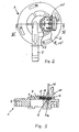
- eine Draufsicht auf den erfindungsgemäßen Sensorträger im fertigen Zustand; und
- Fig. 3
- eine Schnittansicht entlang der Linie III-III durch den Sensorträger der
Fig. 2 . - Bei dem in den Figuren dargestellten Sensorträger 1 handelt es sich um ein Deckteil für einen Durchflussmesser, wie er als solcher beispielsweise in der
DE 296 14 076 U1 dargestellt ist. - Der erfindungsgemäße Sensorträger 1 weist ein Deckteil 2 auf, welches über - nicht näher dargestellte - Bajonettverschlüsse - mit einem Unterteil des Durchflussmessers (nicht dargestellt) verbindbar ist. Am Deckteil 2 ist ein Fluidanschluss 3, im dargestellten Ausführungsbeispiel die Fluidfortführung ausgebildet. Weiterhin findet sich am Deckteil ein Aufnahmebereich 4 für einen Sensor 5, von dem Verbindungslitzen 6 zu dem Deckteil 2 ausgebildeten Vertiefungen geführt sind. Der Anschlussbereich 4 ist durch eine Nut 7 umgeben. Ein mit dem Deckteil 2 verbindbares Steckerteil 11 des erfindungsgemäßen Sensorträgers 1 trägt im dargestellten Ausführungsbeispiel Anschlussstifte 12, die nach Verbinden des Steckerteils 11 mit dem Deckteil 2 innerhalb der Vertiefungen 7a in elektrisch leitenden Kontakt mit den Enden der Verbindungslitzen 6 gelangen.
- Das Steckerteil 11 weist eine Nase 13 auf, die zum Eingreifen in eine Nut 7 des Deckteils 2 ausgebildet ist. Nach Zusammenstecken von Deckteil 2 und Steckerteil 11 werden diese über in Vertiefungen 8 des Deckteils 2 ein- und hintergreifende Nasen 15 des Steckerteils 11 aneinander gehalten.
- Zur vollständigen Isolierung und Abdichtung gegen eindringende Feuchtigkeit, die insbesondere Kurzschlussbrücken im Bereich der Verbindungslitzen 6 bedingen könnte, ist der Raum zwischen dem Bereich 4 und dem Deckteil 11 durch eine elektrisch isolierende elastische Masse abgedichtet, die in der
Fig. 3 liniert dargestellt ist. Hierbei handelt es sich vorzugsweise um in fließfähiger oder zähflüssiger Form eingebrachtes und nach Aufstecken des Steckerteils mit den Steckstiften 12 ausgehärtetes Silikon. - Durch die isolierende elastische Masse 14 wird ein sicherer Schutz des Sensors 5, der Litzen 6 sowie der Kontaktstifte (letztere im Inneren des Sensorträgers) gegen eindringende Feuchtigkeit gewährleistet.
- Der Verfahrensablauf zur Herstellung des erfindungsgemäßen Sensorträgers beinhaltet nach Spritzen des Deckteils 2 das Aufsetzen des Sensorträgers 5 mit seinen Verbindungslitzen 6 und unter Einbringen der Enden derselben in die Vertiefungen 7a des Deckteils 2. Anschließend wird die isolierende Masse 14 in fließfähigen oder zähflüssigen Zustand in dem Bereich 4 des Deckteils 2 derart aufgebracht, dass die Masse sowohl den Sensorträger 5 als auch die Verbindungslitzen 6 überdeckt. Anschließend wird das Steckerteil 11 mit den schon in diesen reibschlüssig eingebrachten Anschlussstiften 12 aufgesetzt und verrastet mittels der Nasen 15 am Deckteil 2. Dabei wird die zähflüssige isolierende Masse durch Verpressen verteilt und füllt in der in
Fig. 3 dargestellten Weise vollständig den Zwischenraum zwischen Deckteil 2 und Steckerteil 11 im Bereich 4 aus. Anschließend erfolgt ein Aushärten der isolierenden Masse 14, woraufhin der erfindungsgemäße Sensorträger einsetzbar ist und zum Betrieb mit dem (nicht dargestellten) Unterteil des Durchflussmessers verbunden werden kann.
Claims (7)
- Sensorträger mit einem Deckteil für einen Durchflussmesser, mit einem Sensor mit Verbindungslitzen und mit einem den Sensor und die Verbindungslitzen überdeckenden Steckerteil mit mit den Verbindungslitzen in Kontakt bringbaren Anschlussstiften,
dadurch gekennzeichnet,- dass der Zwischenraum zwischen Steckerteil (11) und Deckteil (2) zumindest im Bereich der Verbindungslitzen (6) durch eine elektrisch isolierende, elastische Masse (14) abgedeckt ist,- dass das Steckerteil (11) eine Nase (13) aufweist, die in eine Nut (7) des Deckteils (2) eingreift und- dass Steckerteil (11) und Deckteil (2) über in Vertiefungen (8) des Deckteils (2) ein- und hinter-greifende andere Nasen (15) des Steckerteils (11) gehalten sind. - Sensorträger nach Anspruch 1, dadurch gekennzeichnet, dass der Zwischenraum zwischen Steckerteil (11) und Deckteil (2) vollständig durch die elektrisch isolierende elastische Masse (14) ausgefüllt ist.
- Sensorträger nach Anspruch 1 oder 2, dadurch gekennzeichnet, dass die elektrisch isolierende elastische Masse (14) in fließfähiger oder zähflüssiger Form aufgebracht und ausgehärtet ist.
- Sensorträger nach einem der Ansprüche 1 bis 3, dadurch gekennzeichnet, dass die elektrisch isolierende elastische Masse (14) Silikon ist.
- Verfahren zum Herstellen eines Sensorträgers für einen Durchflussmesser,
dadurch gekennzeichnet,- dass auf ein mit einem mit Verbindungslitzen versehenen Sensor versehenes Deckteil eine elektrisch isolierende Masse in fließfähiger oder zähflüssiger Form aufgebracht und anschließend ein Anschlussstifte tragendes Steckerteil unter Herstellung elektrischen Kontaktes zwischen jeweils einem der Anschlussstifte des Steckerteils und einer Anschlusslitze die elektrisch isolierende Masse überdeckend und verpressend mit dem Deckteil verbunden wird, und- dass Steckerteil (11) und Deckteil zum Zusammenhalten über in Vertiefungen (8) des Deckteils (2) ein- und hintergreifende Nasen (15) des Steckteils (11) zusammengesteckt werden, wobei eine weitere Nase (13) des Steckerteils (11) in eine Nut (7) des Deckteils (2) eingreift. - Verfahren nach Anspruch 5, dadurch gekennzeichnet, dass Deckteil und Steckerteil in formschlüssigen Kontakt miteinander gebracht werden.
- Verfahren nach Anspruch 5 oder 6, dadurch gekennzeichnet, dass als elektrisch isolierende Masse Silikon in fließfähiger oder zähflüssiger Form den vom Steckerteil überdeckten Bereich des Deckteils oder auf die dem Deckteil zugewandte Seite des Steckerteils aufgebracht wird.
Applications Claiming Priority (1)
| Application Number | Priority Date | Filing Date | Title |
|---|---|---|---|
| DE202004010954U DE202004010954U1 (de) | 2004-07-13 | 2004-07-13 | Sensorträger für einen Durchflussmesser |
Publications (3)
| Publication Number | Publication Date |
|---|---|
| EP1617187A2 EP1617187A2 (de) | 2006-01-18 |
| EP1617187A3 EP1617187A3 (de) | 2009-12-30 |
| EP1617187B1 true EP1617187B1 (de) | 2012-06-20 |
Family
ID=34895678
Family Applications (1)
| Application Number | Title | Priority Date | Filing Date |
|---|---|---|---|
| EP05014914A Expired - Lifetime EP1617187B1 (de) | 2004-07-13 | 2005-07-09 | Sensorträger für einen Durchflussmesser |
Country Status (6)
| Country | Link |
|---|---|
| US (1) | US7357024B2 (de) |
| EP (1) | EP1617187B1 (de) |
| CN (1) | CN1721825A (de) |
| DE (1) | DE202004010954U1 (de) |
| DK (1) | DK1617187T3 (de) |
| ES (1) | ES2388858T3 (de) |
Families Citing this family (5)
| Publication number | Priority date | Publication date | Assignee | Title |
|---|---|---|---|---|
| JP2007315792A (ja) | 2006-05-23 | 2007-12-06 | Mitsubishi Electric Corp | 圧力センサの取り付け構造 |
| DE102007019610A1 (de) * | 2007-04-24 | 2008-10-30 | Endress + Hauser Flowtec Ag | Vorrichtung zur Befestigung einer Mess- oder Anzeigeeinheit an einem Gegenstand |
| DE202007018962U1 (de) * | 2007-11-05 | 2010-04-01 | Digmesa Ag | Oberteil für einen Durchflussmesser und Durchflussmesser |
| JP2009270995A (ja) * | 2008-05-09 | 2009-11-19 | Nidec Sankyo Corp | 流量計 |
| US20180225049A1 (en) * | 2017-02-03 | 2018-08-09 | Sensors Unlimited, Inc. | Media recording systems |
Family Cites Families (9)
| Publication number | Priority date | Publication date | Assignee | Title |
|---|---|---|---|---|
| IT8321544U1 (it) * | 1983-04-14 | 1984-10-14 | Nuova Faema Spa | Dispositivo dosatore dell'acqua per macchine per il caffe' espresso, munito di una girante. |
| DE9017839U1 (de) * | 1990-12-18 | 1992-04-30 | VSE Volumentechnik GmbH, 58809 Neuenrade | Volumensensor |
| FR2731237B1 (fr) * | 1995-03-02 | 1997-04-30 | Seb Sa | Structure chauffante, notamment pour appareil electromenager realise selon une structure sandwich et appareil electromenager comportant une telle structure chauffante |
| DE29614076U1 (de) * | 1996-08-15 | 1997-09-11 | Digmesa AG, Biel | Durchflußmeßgerät |
| FR2770077B1 (fr) * | 1997-10-17 | 2002-03-01 | Moulinex Sa | Chaudiere pour appareil electromenager et appareil electromenager comportant une telle chaudiere |
| JP2001255183A (ja) * | 2000-03-13 | 2001-09-21 | Saginomiya Seisakusho Inc | フローセンサ |
| US6622555B2 (en) * | 2001-10-11 | 2003-09-23 | Visteon Global Technologies, Inc. | Fluid flow meter |
| US6487919B1 (en) * | 2001-11-06 | 2002-12-03 | Breed Automotive Technology, Inc. | Turbine flow monitoring device |
| WO2004081526A2 (en) * | 2003-03-07 | 2004-09-23 | Upchurch Scientific, Inc. | Microfluidic isolation manifold and methods for microfluidic isolation |
-
2004
- 2004-07-13 DE DE202004010954U patent/DE202004010954U1/de not_active Expired - Lifetime
-
2005
- 2005-07-09 ES ES05014914T patent/ES2388858T3/es not_active Expired - Lifetime
- 2005-07-09 EP EP05014914A patent/EP1617187B1/de not_active Expired - Lifetime
- 2005-07-09 DK DK05014914.5T patent/DK1617187T3/da active
- 2005-07-11 US US11/177,398 patent/US7357024B2/en not_active Expired - Lifetime
- 2005-07-13 CN CN200510083606.7A patent/CN1721825A/zh active Pending
Also Published As
| Publication number | Publication date |
|---|---|
| EP1617187A3 (de) | 2009-12-30 |
| US7357024B2 (en) | 2008-04-15 |
| EP1617187A2 (de) | 2006-01-18 |
| ES2388858T3 (es) | 2012-10-19 |
| CN1721825A (zh) | 2006-01-18 |
| US20060010975A1 (en) | 2006-01-19 |
| DK1617187T3 (da) | 2012-09-10 |
| DE202004010954U1 (de) | 2005-08-25 |
Similar Documents
| Publication | Publication Date | Title |
|---|---|---|
| EP2792029B1 (de) | Fluiddichte kontaktdurchführung | |
| EP1396705B1 (de) | Flussdetektor mit Durchführungen und Verfahren zu dessen Herstellung | |
| EP2695246B1 (de) | Abdichtung von gehäusen für steckkontaktelemente | |
| DE102007054717B4 (de) | Transmitter und Verfahren zur Herstellung eines Transmitters | |
| EP2309604A1 (de) | Elektrisch leitende Verbindung und Verbundglasscheibe damit | |
| WO2008098953A1 (de) | Modulares messgerät und verfahren zu seiner herstellung | |
| WO2013167570A1 (de) | Steckverbinder, steuergerät und verfahren zur herstellung eines steuergeräts | |
| DE102013202860B4 (de) | Verstellantrieb, Verfahren zum Herstellen eines Verstellantriebs sowie dessen Verwendung | |
| DE102013215369B4 (de) | Stecker, Steuergerät und Verfahren zur Herstellung eines Steckers | |
| DE19922139B4 (de) | Verfahren zur Montage eines Flachkabels an einem Stecker, Stecker für ein Flachkabel und Bauteil zum Erregen von Ultraschallschwingungen zur Verwendung bei diesem Verfahren | |
| DE202013103402U1 (de) | Temperatursensor und thermisches Durchflussmessgerät | |
| DE10111336A1 (de) | Sensor, insbesondere Temperatur-Sensor, mit einem Messwiderstand | |
| EP1617187A2 (de) | Sensorträger für einen Durchflussmesser | |
| EP1479958B1 (de) | Vorrichtung zur Abdichtung von eingesetzten Leitungen und/oder Kabeln | |
| DE102013221239B4 (de) | Steuerungseinrichtung | |
| DE102007018175A1 (de) | Stromverteiler für Leitungssatz inbesondere in einem Kraftfahrzeug | |
| WO2018024285A1 (de) | Kabelverbinder | |
| EP2001085A1 (de) | Verfahren zur Herstellung einer elektrisch leitenden Verbindung | |
| DE102019124229A1 (de) | Leistungselektronikmodul mit über einen Haftvermittler angebrachten Dichtungsummantelung; elektrische Antriebsmaschine; sowie Herstellverfahren | |
| DE202007018962U1 (de) | Oberteil für einen Durchflussmesser und Durchflussmesser | |
| AT510196B1 (de) | Solarmodul und verfahren zu seiner herstellung | |
| EP1071311A1 (de) | Kapselung für das An- oder das Abschlussende eines elektrischen Heizbandkabels und Verfahren zu seiner Herstellung | |
| EP3084897B1 (de) | Elektrische baugruppe | |
| EP4223088B1 (de) | Elektronisches gerät und entsprechende baureihe | |
| DE102011120864B4 (de) | Mehrpoliges Reitersicherungselement |
Legal Events
| Date | Code | Title | Description |
|---|---|---|---|
| PUAI | Public reference made under article 153(3) epc to a published international application that has entered the european phase |
Free format text: ORIGINAL CODE: 0009012 |
|
| AK | Designated contracting states |
Kind code of ref document: A2 Designated state(s): AT BE BG CH CY CZ DE DK EE ES FI FR GB GR HU IE IS IT LI LT LU LV MC NL PL PT RO SE SI SK TR |
|
| AX | Request for extension of the european patent |
Extension state: AL BA HR MK YU |
|
| PUAL | Search report despatched |
Free format text: ORIGINAL CODE: 0009013 |
|
| AK | Designated contracting states |
Kind code of ref document: A3 Designated state(s): AT BE BG CH CY CZ DE DK EE ES FI FR GB GR HU IE IS IT LI LT LU LV MC NL PL PT RO SE SI SK TR |
|
| AX | Request for extension of the european patent |
Extension state: AL BA HR MK YU |
|
| 17P | Request for examination filed |
Effective date: 20100216 |
|
| AKX | Designation fees paid |
Designated state(s): AT BE BG CH CY CZ DE DK EE ES FI FR GB GR HU IE IS IT LI LT LU LV MC NL PL PT RO SE SI SK TR |
|
| 17Q | First examination report despatched |
Effective date: 20110825 |
|
| GRAP | Despatch of communication of intention to grant a patent |
Free format text: ORIGINAL CODE: EPIDOSNIGR1 |
|
| GRAS | Grant fee paid |
Free format text: ORIGINAL CODE: EPIDOSNIGR3 |
|
| GRAA | (expected) grant |
Free format text: ORIGINAL CODE: 0009210 |
|
| AK | Designated contracting states |
Kind code of ref document: B1 Designated state(s): AT BE BG CH CY CZ DE DK EE ES FI FR GB GR HU IE IS IT LI LT LU LV MC NL PL PT RO SE SI SK TR |
|
| REG | Reference to a national code |
Ref country code: GB Ref legal event code: FG4D Free format text: NOT ENGLISH |
|
| REG | Reference to a national code |
Ref country code: CH Ref legal event code: EP |
|
| REG | Reference to a national code |
Ref country code: AT Ref legal event code: REF Ref document number: 563314 Country of ref document: AT Kind code of ref document: T Effective date: 20120715 |
|
| REG | Reference to a national code |
Ref country code: IE Ref legal event code: FG4D Free format text: LANGUAGE OF EP DOCUMENT: GERMAN |
|
| REG | Reference to a national code |
Ref country code: CH Ref legal event code: NV Representative=s name: TROESCH SCHEIDEGGER WERNER AG |
|
| REG | Reference to a national code |
Ref country code: DE Ref legal event code: R096 Ref document number: 502005012847 Country of ref document: DE Effective date: 20120816 |
|
| REG | Reference to a national code |
Ref country code: DK Ref legal event code: T3 |
|
| REG | Reference to a national code |
Ref country code: NL Ref legal event code: T3 |
|
| REG | Reference to a national code |
Ref country code: SE Ref legal event code: TRGR |
|
| REG | Reference to a national code |
Ref country code: ES Ref legal event code: FG2A Ref document number: 2388858 Country of ref document: ES Kind code of ref document: T3 Effective date: 20121019 |
|
| PG25 | Lapsed in a contracting state [announced via postgrant information from national office to epo] |
Ref country code: FI Free format text: LAPSE BECAUSE OF FAILURE TO SUBMIT A TRANSLATION OF THE DESCRIPTION OR TO PAY THE FEE WITHIN THE PRESCRIBED TIME-LIMIT Effective date: 20120620 Ref country code: LT Free format text: LAPSE BECAUSE OF FAILURE TO SUBMIT A TRANSLATION OF THE DESCRIPTION OR TO PAY THE FEE WITHIN THE PRESCRIBED TIME-LIMIT Effective date: 20120620 |
|
| REG | Reference to a national code |
Ref country code: LT Ref legal event code: MG4D Effective date: 20120620 |
|
| PG25 | Lapsed in a contracting state [announced via postgrant information from national office to epo] |
Ref country code: LV Free format text: LAPSE BECAUSE OF FAILURE TO SUBMIT A TRANSLATION OF THE DESCRIPTION OR TO PAY THE FEE WITHIN THE PRESCRIBED TIME-LIMIT Effective date: 20120620 Ref country code: SI Free format text: LAPSE BECAUSE OF FAILURE TO SUBMIT A TRANSLATION OF THE DESCRIPTION OR TO PAY THE FEE WITHIN THE PRESCRIBED TIME-LIMIT Effective date: 20120620 Ref country code: GR Free format text: LAPSE BECAUSE OF FAILURE TO SUBMIT A TRANSLATION OF THE DESCRIPTION OR TO PAY THE FEE WITHIN THE PRESCRIBED TIME-LIMIT Effective date: 20120921 |
|
| PG25 | Lapsed in a contracting state [announced via postgrant information from national office to epo] |
Ref country code: RO Free format text: LAPSE BECAUSE OF FAILURE TO SUBMIT A TRANSLATION OF THE DESCRIPTION OR TO PAY THE FEE WITHIN THE PRESCRIBED TIME-LIMIT Effective date: 20120620 Ref country code: CY Free format text: LAPSE BECAUSE OF FAILURE TO SUBMIT A TRANSLATION OF THE DESCRIPTION OR TO PAY THE FEE WITHIN THE PRESCRIBED TIME-LIMIT Effective date: 20120620 Ref country code: IS Free format text: LAPSE BECAUSE OF FAILURE TO SUBMIT A TRANSLATION OF THE DESCRIPTION OR TO PAY THE FEE WITHIN THE PRESCRIBED TIME-LIMIT Effective date: 20121020 Ref country code: CZ Free format text: LAPSE BECAUSE OF FAILURE TO SUBMIT A TRANSLATION OF THE DESCRIPTION OR TO PAY THE FEE WITHIN THE PRESCRIBED TIME-LIMIT Effective date: 20120620 Ref country code: EE Free format text: LAPSE BECAUSE OF FAILURE TO SUBMIT A TRANSLATION OF THE DESCRIPTION OR TO PAY THE FEE WITHIN THE PRESCRIBED TIME-LIMIT Effective date: 20120620 Ref country code: SK Free format text: LAPSE BECAUSE OF FAILURE TO SUBMIT A TRANSLATION OF THE DESCRIPTION OR TO PAY THE FEE WITHIN THE PRESCRIBED TIME-LIMIT Effective date: 20120620 |
|
| PG25 | Lapsed in a contracting state [announced via postgrant information from national office to epo] |
Ref country code: PT Free format text: LAPSE BECAUSE OF FAILURE TO SUBMIT A TRANSLATION OF THE DESCRIPTION OR TO PAY THE FEE WITHIN THE PRESCRIBED TIME-LIMIT Effective date: 20121022 Ref country code: PL Free format text: LAPSE BECAUSE OF FAILURE TO SUBMIT A TRANSLATION OF THE DESCRIPTION OR TO PAY THE FEE WITHIN THE PRESCRIBED TIME-LIMIT Effective date: 20120620 Ref country code: MC Free format text: LAPSE BECAUSE OF NON-PAYMENT OF DUE FEES Effective date: 20120731 |
|
| PLBE | No opposition filed within time limit |
Free format text: ORIGINAL CODE: 0009261 |
|
| STAA | Information on the status of an ep patent application or granted ep patent |
Free format text: STATUS: NO OPPOSITION FILED WITHIN TIME LIMIT |
|
| REG | Reference to a national code |
Ref country code: IE Ref legal event code: MM4A |
|
| 26N | No opposition filed |
Effective date: 20130321 |
|
| REG | Reference to a national code |
Ref country code: DE Ref legal event code: R097 Ref document number: 502005012847 Country of ref document: DE Effective date: 20130321 |
|
| PG25 | Lapsed in a contracting state [announced via postgrant information from national office to epo] |
Ref country code: BG Free format text: LAPSE BECAUSE OF FAILURE TO SUBMIT A TRANSLATION OF THE DESCRIPTION OR TO PAY THE FEE WITHIN THE PRESCRIBED TIME-LIMIT Effective date: 20120920 Ref country code: IE Free format text: LAPSE BECAUSE OF NON-PAYMENT OF DUE FEES Effective date: 20120709 |
|
| PG25 | Lapsed in a contracting state [announced via postgrant information from national office to epo] |
Ref country code: TR Free format text: LAPSE BECAUSE OF FAILURE TO SUBMIT A TRANSLATION OF THE DESCRIPTION OR TO PAY THE FEE WITHIN THE PRESCRIBED TIME-LIMIT Effective date: 20120620 |
|
| PG25 | Lapsed in a contracting state [announced via postgrant information from national office to epo] |
Ref country code: LU Free format text: LAPSE BECAUSE OF NON-PAYMENT OF DUE FEES Effective date: 20120709 |
|
| PG25 | Lapsed in a contracting state [announced via postgrant information from national office to epo] |
Ref country code: HU Free format text: LAPSE BECAUSE OF FAILURE TO SUBMIT A TRANSLATION OF THE DESCRIPTION OR TO PAY THE FEE WITHIN THE PRESCRIBED TIME-LIMIT Effective date: 20050709 |
|
| REG | Reference to a national code |
Ref country code: FR Ref legal event code: PLFP Year of fee payment: 12 |
|
| REG | Reference to a national code |
Ref country code: FR Ref legal event code: PLFP Year of fee payment: 13 |
|
| REG | Reference to a national code |
Ref country code: FR Ref legal event code: PLFP Year of fee payment: 14 |
|
| P01 | Opt-out of the competence of the unified patent court (upc) registered |
Effective date: 20230421 |
|
| PGFP | Annual fee paid to national office [announced via postgrant information from national office to epo] |
Ref country code: NL Payment date: 20240722 Year of fee payment: 20 |
|
| PGFP | Annual fee paid to national office [announced via postgrant information from national office to epo] |
Ref country code: DE Payment date: 20240711 Year of fee payment: 20 |
|
| PGFP | Annual fee paid to national office [announced via postgrant information from national office to epo] |
Ref country code: DK Payment date: 20240722 Year of fee payment: 20 |
|
| PGFP | Annual fee paid to national office [announced via postgrant information from national office to epo] |
Ref country code: GB Payment date: 20240723 Year of fee payment: 20 |
|
| PGFP | Annual fee paid to national office [announced via postgrant information from national office to epo] |
Ref country code: BE Payment date: 20240722 Year of fee payment: 20 |
|
| PGFP | Annual fee paid to national office [announced via postgrant information from national office to epo] |
Ref country code: FR Payment date: 20240731 Year of fee payment: 20 |
|
| PGFP | Annual fee paid to national office [announced via postgrant information from national office to epo] |
Ref country code: ES Payment date: 20240816 Year of fee payment: 20 Ref country code: CH Payment date: 20240801 Year of fee payment: 20 |
|
| PGFP | Annual fee paid to national office [announced via postgrant information from national office to epo] |
Ref country code: AT Payment date: 20240718 Year of fee payment: 20 |
|
| PGFP | Annual fee paid to national office [announced via postgrant information from national office to epo] |
Ref country code: IT Payment date: 20240731 Year of fee payment: 20 Ref country code: SE Payment date: 20240722 Year of fee payment: 20 |
|
| REG | Reference to a national code |
Ref country code: NL Ref legal event code: MK Effective date: 20250708 Ref country code: DE Ref legal event code: R071 Ref document number: 502005012847 Country of ref document: DE |
|
| REG | Reference to a national code |
Ref country code: DK Ref legal event code: EUP Expiry date: 20250709 |
|
| REG | Reference to a national code |
Ref country code: CH Ref legal event code: PL |
|
| REG | Reference to a national code |
Ref country code: GB Ref legal event code: PE20 Expiry date: 20250708 |
|
| REG | Reference to a national code |
Ref country code: ES Ref legal event code: FD2A Effective date: 20250801 |
|
| REG | Reference to a national code |
Ref country code: BE Ref legal event code: MK Effective date: 20250709 |
|
| REG | Reference to a national code |
Ref country code: SE Ref legal event code: EUG |
|
| PG25 | Lapsed in a contracting state [announced via postgrant information from national office to epo] |
Ref country code: ES Free format text: LAPSE BECAUSE OF EXPIRATION OF PROTECTION Effective date: 20250710 |