EP1617043B1 - Methode zur Kühlung einer Wand in einer Gasturbine - Google Patents
Methode zur Kühlung einer Wand in einer Gasturbine Download PDFInfo
- Publication number
- EP1617043B1 EP1617043B1 EP05021709A EP05021709A EP1617043B1 EP 1617043 B1 EP1617043 B1 EP 1617043B1 EP 05021709 A EP05021709 A EP 05021709A EP 05021709 A EP05021709 A EP 05021709A EP 1617043 B1 EP1617043 B1 EP 1617043B1
- Authority
- EP
- European Patent Office
- Prior art keywords
- cooling
- wall
- pedestals
- cooling circuit
- passage
- Prior art date
- Legal status (The legal status is an assumption and is not a legal conclusion. Google has not performed a legal analysis and makes no representation as to the accuracy of the status listed.)
- Expired - Lifetime
Links
Images
Classifications
-
- F—MECHANICAL ENGINEERING; LIGHTING; HEATING; WEAPONS; BLASTING
- F01—MACHINES OR ENGINES IN GENERAL; ENGINE PLANTS IN GENERAL; STEAM ENGINES
- F01D—NON-POSITIVE DISPLACEMENT MACHINES OR ENGINES, e.g. STEAM TURBINES
- F01D5/00—Blades; Blade-carrying members; Heating, heat-insulating, cooling or antivibration means on the blades or the members
- F01D5/12—Blades
- F01D5/14—Form or construction
- F01D5/18—Hollow blades, i.e. blades with cooling or heating channels or cavities; Heating, heat-insulating or cooling means on blades
- F01D5/186—Film cooling
-
- F—MECHANICAL ENGINEERING; LIGHTING; HEATING; WEAPONS; BLASTING
- F01—MACHINES OR ENGINES IN GENERAL; ENGINE PLANTS IN GENERAL; STEAM ENGINES
- F01D—NON-POSITIVE DISPLACEMENT MACHINES OR ENGINES, e.g. STEAM TURBINES
- F01D25/00—Component parts, details, or accessories, not provided for in, or of interest apart from, other groups
- F01D25/08—Cooling; Heating; Heat-insulation
- F01D25/12—Cooling
-
- F—MECHANICAL ENGINEERING; LIGHTING; HEATING; WEAPONS; BLASTING
- F01—MACHINES OR ENGINES IN GENERAL; ENGINE PLANTS IN GENERAL; STEAM ENGINES
- F01D—NON-POSITIVE DISPLACEMENT MACHINES OR ENGINES, e.g. STEAM TURBINES
- F01D5/00—Blades; Blade-carrying members; Heating, heat-insulating, cooling or antivibration means on the blades or the members
- F01D5/12—Blades
- F01D5/14—Form or construction
- F01D5/18—Hollow blades, i.e. blades with cooling or heating channels or cavities; Heating, heat-insulating or cooling means on blades
- F01D5/187—Convection cooling
-
- F—MECHANICAL ENGINEERING; LIGHTING; HEATING; WEAPONS; BLASTING
- F05—INDEXING SCHEMES RELATING TO ENGINES OR PUMPS IN VARIOUS SUBCLASSES OF CLASSES F01-F04
- F05D—INDEXING SCHEME FOR ASPECTS RELATING TO NON-POSITIVE-DISPLACEMENT MACHINES OR ENGINES, GAS-TURBINES OR JET-PROPULSION PLANTS
- F05D2260/00—Function
- F05D2260/20—Heat transfer, e.g. cooling
- F05D2260/202—Heat transfer, e.g. cooling by film cooling
-
- F—MECHANICAL ENGINEERING; LIGHTING; HEATING; WEAPONS; BLASTING
- F05—INDEXING SCHEMES RELATING TO ENGINES OR PUMPS IN VARIOUS SUBCLASSES OF CLASSES F01-F04
- F05D—INDEXING SCHEME FOR ASPECTS RELATING TO NON-POSITIVE-DISPLACEMENT MACHINES OR ENGINES, GAS-TURBINES OR JET-PROPULSION PLANTS
- F05D2260/00—Function
- F05D2260/20—Heat transfer, e.g. cooling
- F05D2260/221—Improvement of heat transfer
- F05D2260/2212—Improvement of heat transfer by creating turbulence
-
- F—MECHANICAL ENGINEERING; LIGHTING; HEATING; WEAPONS; BLASTING
- F05—INDEXING SCHEMES RELATING TO ENGINES OR PUMPS IN VARIOUS SUBCLASSES OF CLASSES F01-F04
- F05D—INDEXING SCHEME FOR ASPECTS RELATING TO NON-POSITIVE-DISPLACEMENT MACHINES OR ENGINES, GAS-TURBINES OR JET-PROPULSION PLANTS
- F05D2260/00—Function
- F05D2260/20—Heat transfer, e.g. cooling
- F05D2260/221—Improvement of heat transfer
- F05D2260/2214—Improvement of heat transfer by increasing the heat transfer surface
- F05D2260/22141—Improvement of heat transfer by increasing the heat transfer surface using fins or ribs
Definitions
- This invention relates to gas turbine engines in general, and to cooling passages disposed within a wall inside of a gas turbine engine in particular.
- EP1091092 A2 state of the art in accordance with Article 54(3) EPC
- EP 0896127 A2 GB 1257041
- WO 01/00964 A1 state of the art in accordance with Article 54(3) EPC
- EP 0742347 A2 US 4,278,400 and EP 0945595 A2 all disclose prior methods for cooling gas turbine airfoils.
- US 5,649,806 discloses a prior art method for cooling turbine blade outer air seals.
- a typical gas turbine engine includes a fan, compressor, combustor, and turbine disposed along a common longitudinal axis.
- the fan and compressor sections work the air drawn into the engine, increasing the pressure and temperature of the air.
- Fuel is added to the worked air and the mixture is burned within the combustor.
- the combustion products and any unburned air hereinafter collectively referred to as core gas, subsequently powers the turbine and exits the engine producing thrust.
- the turbine comprises a plurality of stages each having a rotor assembly and a stationary vane assembly.
- the core gas passing through the turbine causes the turbine rotors to rotate, thereby enabling the rotors to do work elsewhere in the engine.
- the stationary vane assemblies located forward and/or aft of the rotor assemblies guide the core gas flow entering and/or exiting the rotor assemblies.
- Liners which include blade outer air seals, maintain the core gas within the core gas path that extends through the engine.
- cooling air that exits the wall with unspent cooling potential One cause of inefficient cooling can be found in cooling air that exits the wall with unspent cooling potential.
- a person of skill in the art will recognize that cooling air passed through a conventional cooling aperture typically contains cooling potential that is subsequently wasted within the core gas flow.
- the present invention provides convective cooling means that can be tailored to remove an increased amount of cooling potential from the cooling air prior to its exit thereby favorably affecting the cooling effectiveness of the wall.
- One of the problems associated with using apertures to establish a cooling air film is the film's sensitivity to pressure difference across the apertures. Too great a pressure difference across an aperture will cause the air to jet out into the passing core gas rather than aid in the formation of a film of cooling air. Too small a pressure difference will result in negligible cooling airflow through the aperture, or worse, an in-flow of hot core gas. Both cases adversely affect film cooling effectiveness.
- Another problem associated with using apertures to establish film cooling is that cooling air is dispensed from discrete points, rather than along a continuous line. The gaps between the apertures and areas immediately downstream of those gaps are exposed to less cooling air than are the apertures and the spaces immediately downstream of the apertures, and are therefore more susceptible to thermal degradation.
- an object of the present invention to provide a method for cooling a wall having a selectively adjustable heat transfer profile that can be adjusted to substantially match a thermal load profile.
- a method of cooling a wall of a hollow gas turbine airfoil is provided, as set forth in claim 1.
- the invention is characterised over the disclosure of EP 0742347 A2 .
- the cooling circuits provided by the method of the present invention are designed to accommodate non-uniform thermal profiles.
- the temperature of cooling air traveling through a passage increases exponentially as a function of the distance traveled within the passage.
- the exit of a cooling aperture is consequently exposed to higher temperature, and therefore less effective, cooling air than is the inlet.
- the wall portion containing the passage is often externally cooled by a film of cooling air.
- the film of cooling air increases in temperature and degrades as it travels aft, both of which result in a decrease in cooling and consequent higher wall temperature traveling in the aft direction.
- the present invention cooling circuit advantageously avoids undesirable overcooling by providing a method and an apparatus capable of creating a heat transfer cooling profile that substantially offsets the profile of the thermal load applied to the wall portion along the length of the cooling circuit.
- Another advantage of the present cooling circuits is a decrease in thermal stress within the component wall. Thermal stress often results from temperature gradients within the wall; the steeper the gradient, the more likely it will induce undesirable stress within the wall.
- the ability of the present cooling circuit to produce a heat transfer profile that substantially offsets the local thermal load profile of the wall decreases the possibility that thermal stress will grow within the wall.
- Each cooling circuit is an independent compartment designed to internally provide a plurality of incremental pressure drops between the inlet aperture and the exit apertures. The pressure drops allow for a low pressure drop across the inlet aperture and that increases the likelihood that there will always be a positive flow of cooling air into the cooling circuit. The positive flow of cooling air through the circuit, in turn, decreases the chance that hot core gas will undesirably flow into the cooling circuit.
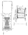
- a gas turbine engine 10 includes a fan 12, a compressor 14, a combustor 16, a turbine 18, and a nozzle 20.
- a fan 12 Within and aft of the combustor 16, most components exposed to core gas are cooled because of the extreme temperature of the core gas.
- the initial rotor stages 22 and stator vane stages 24 within the turbine 18, for example, are cooled using cooling air bled off a compressor stage 14 at a pressure higher and temperature lower than the core gas passing through the turbine 18.
- the cooling air is passed through one or more cooling circuits 26 ( FIG.2 ) disposed within a wall of a hollow airfoil 29 to transfer thermal energy from the wall to the cooling air.
- Each cooling circuit 26 can be disposed in any wall of a hollow airfoil that requires cooling, and in most cases the wall is exposed to core gas flow on one side and cooling air on the other side.
- the present cooling circuit 26 will be described herein as being disposed within a wall 28 of a hollow airfoil 29 portion of a stator vane or a rotor blade.
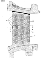
- each cooling circuit 26 includes a forward end 30, an aft end 32, a first wall portion 34, a second wall portion 36, a first side 38, a second side 40, a plurality of first pedestals 42, and a plurality of alternately disposed T-shaped second pedestals 43 and third pedestals 45.
- the third pedestals are shaped to nest between adjacent T -shaped second pedestals 43.
- the first wall portion 34 has a cooling-air side surface 44 and a circuit-side surface 46.
- the second wall portion 36 has a core-gas side surface 48 and a circuit-side surface 50.
- the first wall portion 34 and the second wall portion 36 extend lengthwise 52 between the forward end 30 and the aft end 32 of the cooling circuit 26, and widthwise 54 between the first side 38 and second side 40.
- the plurality of first pedestals 42 extend between the circuit-side surfaces 46,50 of the wall portions 34,36.
- One inlet aperture 56 extends through the first wall portion 34, providing a cooling airflow path into the forward end 30 of the cooling circuit 26 from the cavity 58 of the airfoil 29.
- a plurality of exit apertures 60 provide a cooling airflow path out of the aft end 32 of the cooling circuit 26 and into the core gas path outside the wall 28.
- the exit apertures 60 are formed between the T-shaped second pedestals 43 and nested third pedestals 45, the first wall portion 34, and the second wall portion 36.
- the plurality of exit apertures 60 are connected to the core-gas side surface 48 by a slot 70 extending through the second wall portion 36.
- the size, number, and position of the first pedestals 42 within the cooling circuit 26 are chosen to provide a heat transfer cooling profile within the cooling circuit 26 that substantially offsets the profile of the thermal load applied to the portion of the wall containing the cooling circuit 26; i.e., the cooling circuit may be selectively "tuned" to offset the thermal load. For example, if a portion of wall is subjected to a thermal load that increases in the direction extending forward to aft (as is described above), the size and distribution of the first pedestal s 42 within the present cooling circuit 26 are chosen to progressively increase the heat transfer rate within the cooling circuit 26, thereby providing greater heat transfer where it is needed to offset the thermal load.
- circuit cross -sectional area shall be defined as the area within a plane extending across the width 54 of the circuit through which cooling air may pass.
- the decrease in the circuit cross -sectional area will cause the cooling air to increase in velocity and the increased velocity will positively affect convective cooling in that region. Hence, the increase in heat transfer rate. If, for example, all of the first pedestals 42 have the same cross-sectional geometry, increasing the number of first pedestals 42 at a particular lengthwise position within the circuit 26 will decrease the circuit cross -sectional area.
- the circuit cross-sectional area can also be decreased by increasing the width or changing the geometry of the first pedestals 42 to decrease the distance between adjacent first pedestals 42.
- the heat transfer rate can also adjusted by utilizing impingement cooling or tortuous paths that promote convective cooling.
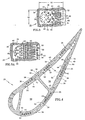
- FIG. 5 shows a distribution of first pedestals 42 that includes first pedestals 42 disposed downstream of and aligned with gaps 62 between upstream first pedestals 42. Cooling air traveling through the upstream gaps 62 is directed toward the downstream pedestals 61 elongated in a widthwise direction. The positioning of the second pedestals 43 encourages impingement cooling.
- the amount by which the convective cooling is increased at any particular lengthwise position within the cooling circuit 26 depends upon the thermal load for that position, for that particular application. It is also useful to size the inlet aperture 56 of the cooling circuit 26 to produce a minimal pressure difference across the aperture 56, thereby preserving cooling potential for downstream use within the cooling circuit 26.
- a cooling circuit heat transfer profile that closely offsets the wall's thermal local thermal load profile will increase the uniformity of the temperature profile across the length of the cooling circuit, ideally creating a constant temperature within the wall portion 36.
Landscapes
- Engineering & Computer Science (AREA)
- Mechanical Engineering (AREA)
- General Engineering & Computer Science (AREA)
- Turbine Rotor Nozzle Sealing (AREA)
Claims (5)
- Verfahren des Kühlens einer Wand (28) eines hohlen Gasturbinenströmungsprofils (29), das die Schritte aufweist:a) Bereitstellen eines Kühlkreises (26) innerhalb der Wand (28), wobei der Kühlkreis aufweist:eine Passage mit einem ersten Ende (30), einem zweiten Ende (32) und einer Breite (54), wobei die Passage zwischen einem ersten Wandbereich (34) und einem zweiten Wandbereich (36) angeordnet ist;eine Mehrzahl von ersten Sockeln (42), die in der Passage angeordnet sind und sich zwischen den Wandbereichen (34, 36) erstrecken;eine Einlassöffnung (56), die einen Kühlluftströmungspfad zwischen einer ersten Seite (44) der Wand und dem ersten Ende (30) der Passage bereitstellt; undeine Mehrzahl von Auslassöffnungen (60), die einen Kühlluftströmungspfad zwischen dem zweiten Ende (32) der Passage und einer zweiten Seite (48) der Wand (28) bereitstellen;b) Bereitstellen von Betriebsbedingungen, die ein thermisches Lastprofil in der Nähe des Kühlkreises beinhalten, dem die Wand wahrscheinlich ausgesetzt ist; undc) selektives Abstimmen des Kühlkreises, um unter diesen Betriebsbedingungen ein Wärmeübertragungsprofil bereitzustellen, das das thermische Lastprofil in der Nähe des Kühlkreises im Wesentlichen ausgleicht;dadurch gekennzeichnet, dass die Einlassöffnung (56) die einzige Einlassöffnung des Kühlkreises ist.
- Verfahren nach Anspruch 1, wobei der Kühlkreis eine Strömungsfläche innerhalb einer Ebene umfasst, die sich in der Breite über die Passage erstreckt, und wobei der Kühlkreis durch Anordnen der Sockel (42) selektiv auf eine Weise abgestimmt wird, die die Strömungsfläche verkleinert und demzufolge die Wärmeübertragung zum Ausgleich der lokalen thermischen Last erhöht.
- Verfahren nach Anspruch 1 oder 2, wobei die Sockel (42) einen im Wesentlichen ähnlichen Querschnitt haben und die Sockel in Reihen angeordnet sind und die Strömungsfläche durch Erhöhen der Anzahl erster Sockel in einer oder mehreren der Reihen verringert wird.
- Verfahren nach einem der vorangehenden Ansprüche, wobei die Sockel (42) in Reihen angeordnet sind und die Strömungsfläche durch Vergrößern der Breite der ersten Sockel in einer oder mehreren der Reihen verringert wird.
- Verfahren nach einem der vorangehenden Ansprüche, wobei die Mehrzahl von Auslassöffnungen (60) durch einen Schlitz (70), der sich durch den zweiten Wandbereich (36) hindurch erstreckt, mit der zweiten Seite (48) der Wand (28) verbunden sind.
Applications Claiming Priority (2)
| Application Number | Priority Date | Filing Date | Title |
|---|---|---|---|
| US09/412,274 US6254334B1 (en) | 1999-10-05 | 1999-10-05 | Method and apparatus for cooling a wall within a gas turbine engine |
| EP00308788A EP1091091B1 (de) | 1999-10-05 | 2000-10-05 | Wand-Kühlkreislauf |
Related Parent Applications (1)
| Application Number | Title | Priority Date | Filing Date |
|---|---|---|---|
| EP00308788A Division EP1091091B1 (de) | 1999-10-05 | 2000-10-05 | Wand-Kühlkreislauf |
Publications (2)
| Publication Number | Publication Date |
|---|---|
| EP1617043A1 EP1617043A1 (de) | 2006-01-18 |
| EP1617043B1 true EP1617043B1 (de) | 2008-06-11 |
Family
ID=23632342
Family Applications (3)
| Application Number | Title | Priority Date | Filing Date |
|---|---|---|---|
| EP05021710A Expired - Lifetime EP1619353B1 (de) | 1999-10-05 | 2000-10-05 | Wand-Kühlkreislauf |
| EP05021709A Expired - Lifetime EP1617043B1 (de) | 1999-10-05 | 2000-10-05 | Methode zur Kühlung einer Wand in einer Gasturbine |
| EP00308788A Expired - Lifetime EP1091091B1 (de) | 1999-10-05 | 2000-10-05 | Wand-Kühlkreislauf |
Family Applications Before (1)
| Application Number | Title | Priority Date | Filing Date |
|---|---|---|---|
| EP05021710A Expired - Lifetime EP1619353B1 (de) | 1999-10-05 | 2000-10-05 | Wand-Kühlkreislauf |
Family Applications After (1)
| Application Number | Title | Priority Date | Filing Date |
|---|---|---|---|
| EP00308788A Expired - Lifetime EP1091091B1 (de) | 1999-10-05 | 2000-10-05 | Wand-Kühlkreislauf |
Country Status (4)
| Country | Link |
|---|---|
| US (1) | US6254334B1 (de) |
| EP (3) | EP1619353B1 (de) |
| JP (1) | JP2001107704A (de) |
| DE (3) | DE60040324D1 (de) |
Families Citing this family (121)
| Publication number | Priority date | Publication date | Assignee | Title |
|---|---|---|---|---|
| DE19737845C2 (de) * | 1997-08-29 | 1999-12-02 | Siemens Ag | Verfahren zum Herstellen einer Gasturbinenschaufel, sowie nach dem Verfahren hergestellte Gasturbinenschaufel |
| US6402470B1 (en) * | 1999-10-05 | 2002-06-11 | United Technologies Corporation | Method and apparatus for cooling a wall within a gas turbine engine |
| DE10001109B4 (de) * | 2000-01-13 | 2012-01-19 | Alstom Technology Ltd. | Gekühlte Schaufel für eine Gasturbine |
| GB0114503D0 (en) * | 2001-06-14 | 2001-08-08 | Rolls Royce Plc | Air cooled aerofoil |
| US6581369B1 (en) | 2001-08-27 | 2003-06-24 | General Electric Company | Heat recovery in test cells for gas turbine engines |
| US6974308B2 (en) * | 2001-11-14 | 2005-12-13 | Honeywell International, Inc. | High effectiveness cooled turbine vane or blade |
| US6681577B2 (en) | 2002-01-16 | 2004-01-27 | General Electric Company | Method and apparatus for relieving stress in a combustion case in a gas turbine engine |
| US7137776B2 (en) * | 2002-06-19 | 2006-11-21 | United Technologies Corporation | Film cooling for microcircuits |
| US6705831B2 (en) * | 2002-06-19 | 2004-03-16 | United Technologies Corporation | Linked, manufacturable, non-plugging microcircuits |
| US7593030B2 (en) * | 2002-07-25 | 2009-09-22 | Intouch Technologies, Inc. | Tele-robotic videoconferencing in a corporate environment |
| US6981846B2 (en) | 2003-03-12 | 2006-01-03 | Florida Turbine Technologies, Inc. | Vortex cooling of turbine blades |
| US7014424B2 (en) * | 2003-04-08 | 2006-03-21 | United Technologies Corporation | Turbine element |
| US6808367B1 (en) | 2003-06-09 | 2004-10-26 | Siemens Westinghouse Power Corporation | Cooling system for a turbine blade having a double outer wall |
| US6832889B1 (en) * | 2003-07-09 | 2004-12-21 | General Electric Company | Integrated bridge turbine blade |
| US6896487B2 (en) * | 2003-08-08 | 2005-05-24 | United Technologies Corporation | Microcircuit airfoil mainbody |
| US6981840B2 (en) * | 2003-10-24 | 2006-01-03 | General Electric Company | Converging pin cooled airfoil |
| US6984103B2 (en) * | 2003-11-20 | 2006-01-10 | General Electric Company | Triple circuit turbine blade |
| US7011502B2 (en) * | 2004-04-15 | 2006-03-14 | General Electric Company | Thermal shield turbine airfoil |
| US7118326B2 (en) * | 2004-06-17 | 2006-10-10 | Siemens Power Generation, Inc. | Cooled gas turbine vane |
| US7478994B2 (en) * | 2004-11-23 | 2009-01-20 | United Technologies Corporation | Airfoil with supplemental cooling channel adjacent leading edge |
| GB2428749B (en) | 2005-08-02 | 2007-11-28 | Rolls Royce Plc | A component comprising a multiplicity of cooling passages |
| US20070227706A1 (en) * | 2005-09-19 | 2007-10-04 | United Technologies Corporation | Compact heat exchanger |
| DE102005050118B4 (de) * | 2005-10-18 | 2009-04-09 | Werkzeugbau Siegfried Hofmann Gmbh | Anordnung zur Temperierung eines metallischen Körpers sowie Verwendung derselben |
| US7364405B2 (en) * | 2005-11-23 | 2008-04-29 | United Technologies Corporation | Microcircuit cooling for vanes |
| US7311498B2 (en) * | 2005-11-23 | 2007-12-25 | United Technologies Corporation | Microcircuit cooling for blades |
| US7600966B2 (en) | 2006-01-17 | 2009-10-13 | United Technologies Corporation | Turbine airfoil with improved cooling |
| EP1813869A3 (de) * | 2006-01-25 | 2013-08-14 | Rolls-Royce plc | Wandelemente für Gasturbinenbrennkammer |
| US7607890B2 (en) | 2006-06-07 | 2009-10-27 | United Technologies Corporation | Robust microcircuits for turbine airfoils |
| EP1881157B1 (de) * | 2006-07-18 | 2014-02-12 | United Technologies Corporation | Serpentinenartige Mikrokanäle zur lokalen Wärmeabfuhr |
| US7581928B1 (en) | 2006-07-28 | 2009-09-01 | United Technologies Corporation | Serpentine microcircuits for hot gas migration |
| US7686582B2 (en) * | 2006-07-28 | 2010-03-30 | United Technologies Corporation | Radial split serpentine microcircuits |
| US7581927B2 (en) * | 2006-07-28 | 2009-09-01 | United Technologies Corporation | Serpentine microcircuit cooling with pressure side features |
| US7780413B2 (en) * | 2006-08-01 | 2010-08-24 | Siemens Energy, Inc. | Turbine airfoil with near wall inflow chambers |
| US9133715B2 (en) * | 2006-09-20 | 2015-09-15 | United Technologies Corporation | Structural members in a pedestal array |
| US7563072B1 (en) * | 2006-09-25 | 2009-07-21 | Florida Turbine Technologies, Inc. | Turbine airfoil with near-wall spiral flow cooling circuit |
| US8197184B2 (en) * | 2006-10-18 | 2012-06-12 | United Technologies Corporation | Vane with enhanced heat transfer |
| US7669425B2 (en) * | 2006-10-25 | 2010-03-02 | Siemens Energy, Inc. | Closed loop turbine cooling fluid reuse system for a turbine engine |
| US7722325B2 (en) * | 2006-11-08 | 2010-05-25 | United Technologies Corporation | Refractory metal core main body trench |
| US7556476B1 (en) * | 2006-11-16 | 2009-07-07 | Florida Turbine Technologies, Inc. | Turbine airfoil with multiple near wall compartment cooling |
| US20080135721A1 (en) * | 2006-12-06 | 2008-06-12 | General Electric Company | Casting compositions for manufacturing metal casting and methods of manufacturing thereof |
| US7938168B2 (en) * | 2006-12-06 | 2011-05-10 | General Electric Company | Ceramic cores, methods of manufacture thereof and articles manufactured from the same |
| US8413709B2 (en) * | 2006-12-06 | 2013-04-09 | General Electric Company | Composite core die, methods of manufacture thereof and articles manufactured therefrom |
| US7624787B2 (en) * | 2006-12-06 | 2009-12-01 | General Electric Company | Disposable insert, and use thereof in a method for manufacturing an airfoil |
| US20100034647A1 (en) * | 2006-12-07 | 2010-02-11 | General Electric Company | Processes for the formation of positive features on shroud components, and related articles |
| US7487819B2 (en) * | 2006-12-11 | 2009-02-10 | General Electric Company | Disposable thin wall core die, methods of manufacture thereof and articles manufactured therefrom |
| US8884182B2 (en) | 2006-12-11 | 2014-11-11 | General Electric Company | Method of modifying the end wall contour in a turbine using laser consolidation and the turbines derived therefrom |
| US7753650B1 (en) | 2006-12-20 | 2010-07-13 | Florida Turbine Technologies, Inc. | Thin turbine rotor blade with sinusoidal flow cooling channels |
| US8757974B2 (en) * | 2007-01-11 | 2014-06-24 | United Technologies Corporation | Cooling circuit flow path for a turbine section airfoil |
| US7837441B2 (en) * | 2007-02-16 | 2010-11-23 | United Technologies Corporation | Impingement skin core cooling for gas turbine engine blade |
| US7946815B2 (en) * | 2007-03-27 | 2011-05-24 | Siemens Energy, Inc. | Airfoil for a gas turbine engine |
| US7854591B2 (en) * | 2007-05-07 | 2010-12-21 | Siemens Energy, Inc. | Airfoil for a turbine of a gas turbine engine |
| US7789625B2 (en) * | 2007-05-07 | 2010-09-07 | Siemens Energy, Inc. | Turbine airfoil with enhanced cooling |
| US7717675B1 (en) * | 2007-05-24 | 2010-05-18 | Florida Turbine Technologies, Inc. | Turbine airfoil with a near wall mini serpentine cooling circuit |
| US10156143B2 (en) * | 2007-12-06 | 2018-12-18 | United Technologies Corporation | Gas turbine engines and related systems involving air-cooled vanes |
| WO2009121715A1 (de) * | 2008-03-31 | 2009-10-08 | Alstom Technology Ltd | Kühlkanalanordnung innerhalb eines hohlgegossenen gussteils |
| JP5182931B2 (ja) * | 2008-05-30 | 2013-04-17 | 三菱重工業株式会社 | タービン用翼 |
| EP2143883A1 (de) * | 2008-07-10 | 2010-01-13 | Siemens Aktiengesellschaft | Turbinenschaufel und entsprechender Gusskern |
| US8096770B2 (en) * | 2008-09-25 | 2012-01-17 | Siemens Energy, Inc. | Trailing edge cooling for turbine blade airfoil |
| US8303253B1 (en) * | 2009-01-22 | 2012-11-06 | Florida Turbine Technologies, Inc. | Turbine airfoil with near-wall mini serpentine cooling channels |
| US8182224B1 (en) * | 2009-02-17 | 2012-05-22 | Florida Turbine Technologies, Inc. | Turbine blade having a row of spanwise nearwall serpentine cooling circuits |
| US8147196B2 (en) * | 2009-05-05 | 2012-04-03 | Siemens Energy, Inc. | Turbine airfoil with a compliant outer wall |
| US9528382B2 (en) * | 2009-11-10 | 2016-12-27 | General Electric Company | Airfoil heat shield |
| US8790083B1 (en) * | 2009-11-17 | 2014-07-29 | Florida Turbine Technologies, Inc. | Turbine airfoil with trailing edge cooling |
| US8511994B2 (en) * | 2009-11-23 | 2013-08-20 | United Technologies Corporation | Serpentine cored airfoil with body microcircuits |
| US8944141B2 (en) * | 2010-12-22 | 2015-02-03 | United Technologies Corporation | Drill to flow mini core |
| US8961133B2 (en) | 2010-12-28 | 2015-02-24 | Rolls-Royce North American Technologies, Inc. | Gas turbine engine and cooled airfoil |
| US10060264B2 (en) * | 2010-12-30 | 2018-08-28 | Rolls-Royce North American Technologies Inc. | Gas turbine engine and cooled flowpath component therefor |
| US8764394B2 (en) | 2011-01-06 | 2014-07-01 | Siemens Energy, Inc. | Component cooling channel |
| US9017027B2 (en) | 2011-01-06 | 2015-04-28 | Siemens Energy, Inc. | Component having cooling channel with hourglass cross section |
| US9011077B2 (en) | 2011-04-20 | 2015-04-21 | Siemens Energy, Inc. | Cooled airfoil in a turbine engine |
| US8807945B2 (en) | 2011-06-22 | 2014-08-19 | United Technologies Corporation | Cooling system for turbine airfoil including ice-cream-cone-shaped pedestals |
| US9249675B2 (en) * | 2011-08-30 | 2016-02-02 | General Electric Company | Pin-fin array |
| US20130052036A1 (en) * | 2011-08-30 | 2013-02-28 | General Electric Company | Pin-fin array |
| US8840363B2 (en) | 2011-09-09 | 2014-09-23 | Siemens Energy, Inc. | Trailing edge cooling system in a turbine airfoil assembly |
| US8882448B2 (en) | 2011-09-09 | 2014-11-11 | Siemens Aktiengesellshaft | Cooling system in a turbine airfoil assembly including zigzag cooling passages interconnected with radial passageways |
| US8882461B2 (en) | 2011-09-12 | 2014-11-11 | Honeywell International Inc. | Gas turbine engines with improved trailing edge cooling arrangements |
| US8840371B2 (en) | 2011-10-07 | 2014-09-23 | General Electric Company | Methods and systems for use in regulating a temperature of components |
| US20130243575A1 (en) * | 2012-03-13 | 2013-09-19 | United Technologies Corporation | Cooling pedestal array |
| BR112014026360A2 (pt) | 2012-04-23 | 2017-06-27 | Gen Electric | aerofólio de turbina e pá de turbina |
| US20130302177A1 (en) * | 2012-05-08 | 2013-11-14 | Robert Frederick Bergholz, JR. | Turbine airfoil trailing edge bifurcated cooling holes |
| US10100645B2 (en) | 2012-08-13 | 2018-10-16 | United Technologies Corporation | Trailing edge cooling configuration for a gas turbine engine airfoil |
| US9267381B2 (en) * | 2012-09-28 | 2016-02-23 | Honeywell International Inc. | Cooled turbine airfoil structures |
| US8951004B2 (en) | 2012-10-23 | 2015-02-10 | Siemens Aktiengesellschaft | Cooling arrangement for a gas turbine component |
| US9995150B2 (en) | 2012-10-23 | 2018-06-12 | Siemens Aktiengesellschaft | Cooling configuration for a gas turbine engine airfoil |
| US8936067B2 (en) | 2012-10-23 | 2015-01-20 | Siemens Aktiengesellschaft | Casting core for a cooling arrangement for a gas turbine component |
| WO2014150681A1 (en) | 2013-03-15 | 2014-09-25 | United Technologies Corporation | Gas turbine engine component having shaped pedestals |
| US8985949B2 (en) | 2013-04-29 | 2015-03-24 | Siemens Aktiengesellschaft | Cooling system including wavy cooling chamber in a trailing edge portion of an airfoil assembly |
| WO2016036366A1 (en) * | 2014-09-04 | 2016-03-10 | Siemens Aktiengesellschaft | Internal cooling system with insert forming nearwall cooling channels in an aft cooling cavity of a gas turbine airfoil |
| US20180045059A1 (en) * | 2014-09-04 | 2018-02-15 | Siemens Aktiengesellschaft | Internal cooling system with insert forming nearwall cooling channels in an aft cooling cavity of a gas turbine airfoil including heat dissipating ribs |
| EP3189214A1 (de) * | 2014-09-04 | 2017-07-12 | Siemens Aktiengesellschaft | Internes kühlsystem mit einsatz zur formung von nahwandigen kühlkanälen in den mittelgurtkühlhohlräumen einer gasturbinenschaufel |
| US20160090843A1 (en) * | 2014-09-30 | 2016-03-31 | General Electric Company | Turbine components with stepped apertures |
| US10352181B2 (en) | 2014-11-26 | 2019-07-16 | Ansaldo Energia Ip Uk Limited | Leading edge cooling channel for airfoil |
| CN107429569B (zh) * | 2015-04-03 | 2019-09-24 | 西门子公司 | 具有低流动框架式通道的涡轮动叶后缘 |
| US10502066B2 (en) | 2015-05-08 | 2019-12-10 | United Technologies Corporation | Turbine engine component including an axially aligned skin core passage interrupted by a pedestal |
| US10323524B2 (en) * | 2015-05-08 | 2019-06-18 | United Technologies Corporation | Axial skin core cooling passage for a turbine engine component |
| US10174620B2 (en) | 2015-10-15 | 2019-01-08 | General Electric Company | Turbine blade |
| US10871075B2 (en) * | 2015-10-27 | 2020-12-22 | Pratt & Whitney Canada Corp. | Cooling passages in a turbine component |
| US9909427B2 (en) | 2015-12-22 | 2018-03-06 | General Electric Company | Turbine airfoil with trailing edge cooling circuit |
| US9938836B2 (en) | 2015-12-22 | 2018-04-10 | General Electric Company | Turbine airfoil with trailing edge cooling circuit |
| US10704395B2 (en) * | 2016-05-10 | 2020-07-07 | General Electric Company | Airfoil with cooling circuit |
| US10808571B2 (en) * | 2017-06-22 | 2020-10-20 | Raytheon Technologies Corporation | Gaspath component including minicore plenums |
| US10502093B2 (en) * | 2017-12-13 | 2019-12-10 | Pratt & Whitney Canada Corp. | Turbine shroud cooling |
| US10648343B2 (en) * | 2018-01-09 | 2020-05-12 | United Technologies Corporation | Double wall turbine gas turbine engine vane platform cooling configuration with main core resupply |
| US10753210B2 (en) * | 2018-05-02 | 2020-08-25 | Raytheon Technologies Corporation | Airfoil having improved cooling scheme |
| US11092017B2 (en) | 2018-11-09 | 2021-08-17 | Raytheon Technologies Corporation | Mini core passage with protrusion |
| US11149556B2 (en) | 2018-11-09 | 2021-10-19 | Raytheon Technologies Corporation | Minicore cooling passage network having sloped impingement surface |
| US11339718B2 (en) * | 2018-11-09 | 2022-05-24 | Raytheon Technologies Corporation | Minicore cooling passage network having trip strips |
| US11352889B2 (en) | 2018-12-18 | 2022-06-07 | General Electric Company | Airfoil tip rail and method of cooling |
| US10767492B2 (en) | 2018-12-18 | 2020-09-08 | General Electric Company | Turbine engine airfoil |
| US11174736B2 (en) | 2018-12-18 | 2021-11-16 | General Electric Company | Method of forming an additively manufactured component |
| US11499433B2 (en) | 2018-12-18 | 2022-11-15 | General Electric Company | Turbine engine component and method of cooling |
| US11566527B2 (en) | 2018-12-18 | 2023-01-31 | General Electric Company | Turbine engine airfoil and method of cooling |
| CN110080828B (zh) * | 2019-04-15 | 2021-09-03 | 西北工业大学 | 一种带线轴型扰流柱及双倒圆出口的网格缝气膜冷却结构 |
| US10844728B2 (en) | 2019-04-17 | 2020-11-24 | General Electric Company | Turbine engine airfoil with a trailing edge |
| US11486257B2 (en) * | 2019-05-03 | 2022-11-01 | Raytheon Technologies Corporation | Cooling passage configuration |
| US12050062B2 (en) | 2021-10-06 | 2024-07-30 | Ge Infrastructure Technology Llc | Stacked cooling assembly for gas turbine combustor |
| US11486259B1 (en) | 2021-11-05 | 2022-11-01 | General Electric Company | Component with cooling passage for a turbine engine |
| US11859511B2 (en) * | 2021-11-05 | 2024-01-02 | Rolls-Royce North American Technologies Inc. | Co and counter flow heat exchanger |
| US11560803B1 (en) | 2021-11-05 | 2023-01-24 | General Electric Company | Component with cooling passage for a turbine engine |
| CN113914938B (zh) * | 2021-12-10 | 2022-02-22 | 中国航发燃气轮机有限公司 | 一种燃气轮机透平气冷叶片 |
| JP2023172704A (ja) * | 2022-05-24 | 2023-12-06 | 三菱重工業株式会社 | タービン翼及びガスタービン |
Family Cites Families (43)
| Publication number | Priority date | Publication date | Assignee | Title |
|---|---|---|---|---|
| GB1257041A (de) * | 1968-03-27 | 1971-12-15 | ||
| US3819295A (en) | 1972-09-21 | 1974-06-25 | Gen Electric | Cooling slot for airfoil blade |
| US3902820A (en) | 1973-07-02 | 1975-09-02 | Westinghouse Electric Corp | Fluid cooled turbine rotor blade |
| US3973874A (en) | 1974-09-25 | 1976-08-10 | General Electric Company | Impingement baffle collars |
| CH584347A5 (de) | 1974-11-08 | 1977-01-31 | Bbc Sulzer Turbomaschinen | |
| US4042162A (en) | 1975-07-11 | 1977-08-16 | General Motors Corporation | Airfoil fabrication |
| US4353679A (en) | 1976-07-29 | 1982-10-12 | General Electric Company | Fluid-cooled element |
| US4080095A (en) | 1976-09-02 | 1978-03-21 | Westinghouse Electric Corporation | Cooled turbine vane |
| US4221539A (en) | 1977-04-20 | 1980-09-09 | The Garrett Corporation | Laminated airfoil and method for turbomachinery |
| US4203706A (en) | 1977-12-28 | 1980-05-20 | United Technologies Corporation | Radial wafer airfoil construction |
| US4185369A (en) | 1978-03-22 | 1980-01-29 | General Electric Company | Method of manufacture of cooled turbine or compressor buckets |
| US4278400A (en) * | 1978-09-05 | 1981-07-14 | United Technologies Corporation | Coolable rotor blade |
| GB2163219B (en) | 1981-10-31 | 1986-08-13 | Rolls Royce | Cooled turbine blade |
| US4487550A (en) | 1983-01-27 | 1984-12-11 | The United States Of America As Represented By The Secretary Of The Air Force | Cooled turbine blade tip closure |
| US4542867A (en) | 1983-01-31 | 1985-09-24 | United Technologies Corporation | Internally cooled hollow airfoil |
| US4529358A (en) | 1984-02-15 | 1985-07-16 | The United States Of America As Represented By The Administrator Of The National Aeronautics And Space Administration | Vortex generating flow passage design for increased film cooling effectiveness |
| US4601638A (en) | 1984-12-21 | 1986-07-22 | United Technologies Corporation | Airfoil trailing edge cooling arrangement |
| US4669957A (en) | 1985-12-23 | 1987-06-02 | United Technologies Corporation | Film coolant passage with swirl diffuser |
| GB2192705B (en) | 1986-07-18 | 1990-06-06 | Rolls Royce Plc | Porous sheet structure for a combustion chamber |
| US4768700A (en) | 1987-08-17 | 1988-09-06 | General Motors Corporation | Diffusion bonding method |
| US5405242A (en) * | 1990-07-09 | 1995-04-11 | United Technologies Corporation | Cooled vane |
| US5383766A (en) * | 1990-07-09 | 1995-01-24 | United Technologies Corporation | Cooled vane |
| US5695320A (en) | 1991-12-17 | 1997-12-09 | General Electric Company | Turbine blade having auxiliary turbulators |
| US5370499A (en) | 1992-02-03 | 1994-12-06 | General Electric Company | Film cooling of turbine airfoil wall using mesh cooling hole arrangement |
| US5403159A (en) | 1992-11-30 | 1995-04-04 | United Technoligies Corporation | Coolable airfoil structure |
| US5344283A (en) | 1993-01-21 | 1994-09-06 | United Technologies Corporation | Turbine vane having dedicated inner platform cooling |
| US5649806A (en) * | 1993-11-22 | 1997-07-22 | United Technologies Corporation | Enhanced film cooling slot for turbine blade outer air seals |
| US5340074A (en) | 1993-12-15 | 1994-08-23 | Accessories Associates, Inc. | Eyeglass display hanger |
| JP3651490B2 (ja) * | 1993-12-28 | 2005-05-25 | 株式会社東芝 | タービン冷却翼 |
| US5484258A (en) | 1994-03-01 | 1996-01-16 | General Electric Company | Turbine airfoil with convectively cooled double shell outer wall |
| US5413458A (en) | 1994-03-29 | 1995-05-09 | United Technologies Corporation | Turbine vane with a platform cavity having a double feed for cooling fluid |
| US5820337A (en) | 1995-01-03 | 1998-10-13 | General Electric Company | Double wall turbine parts |
| EP0742347A3 (de) * | 1995-05-10 | 1998-04-01 | Allison Engine Company, Inc. | Turbinenschaufelkühlung |
| US5772397A (en) * | 1996-05-08 | 1998-06-30 | Alliedsignal Inc. | Gas turbine airfoil with aft internal cooling |
| US5771577A (en) | 1996-05-17 | 1998-06-30 | General Electric Company | Method for making a fluid cooled article with protective coating |
| US5822853A (en) | 1996-06-24 | 1998-10-20 | General Electric Company | Method for making cylindrical structures with cooling channels |
| WO1998025009A1 (de) * | 1996-12-02 | 1998-06-11 | Siemens Aktiengesellschaft | Turbinenschaufel sowie verwendung in einer gasturbinenanlage |
| US5813836A (en) | 1996-12-24 | 1998-09-29 | General Electric Company | Turbine blade |
| US5931638A (en) * | 1997-08-07 | 1999-08-03 | United Technologies Corporation | Turbomachinery airfoil with optimized heat transfer |
| US5976337A (en) * | 1997-10-27 | 1999-11-02 | Allison Engine Company | Method for electrophoretic deposition of brazing material |
| EP0945595A3 (de) * | 1998-03-26 | 2001-10-10 | Mitsubishi Heavy Industries, Ltd. | Gekühlte Gasturbinenschaufel |
| US6213714B1 (en) * | 1999-06-29 | 2001-04-10 | Allison Advanced Development Company | Cooled airfoil |
| US6402470B1 (en) * | 1999-10-05 | 2002-06-11 | United Technologies Corporation | Method and apparatus for cooling a wall within a gas turbine engine |
-
1999
- 1999-10-05 US US09/412,274 patent/US6254334B1/en not_active Expired - Lifetime
-
2000
- 2000-09-28 JP JP2000295597A patent/JP2001107704A/ja active Pending
- 2000-10-05 EP EP05021710A patent/EP1619353B1/de not_active Expired - Lifetime
- 2000-10-05 DE DE60040324T patent/DE60040324D1/de not_active Expired - Lifetime
- 2000-10-05 EP EP05021709A patent/EP1617043B1/de not_active Expired - Lifetime
- 2000-10-05 DE DE60041091T patent/DE60041091D1/de not_active Expired - Lifetime
- 2000-10-05 DE DE60039202T patent/DE60039202D1/de not_active Expired - Lifetime
- 2000-10-05 EP EP00308788A patent/EP1091091B1/de not_active Expired - Lifetime
Also Published As
| Publication number | Publication date |
|---|---|
| EP1091091A2 (de) | 2001-04-11 |
| US6254334B1 (en) | 2001-07-03 |
| DE60040324D1 (de) | 2008-11-06 |
| EP1619353B1 (de) | 2008-12-10 |
| EP1619353A1 (de) | 2006-01-25 |
| EP1091091A3 (de) | 2004-03-24 |
| DE60041091D1 (de) | 2009-01-22 |
| EP1617043A1 (de) | 2006-01-18 |
| EP1091091B1 (de) | 2008-09-24 |
| JP2001107704A (ja) | 2001-04-17 |
| DE60039202D1 (de) | 2008-07-24 |
Similar Documents
| Publication | Publication Date | Title |
|---|---|---|
| EP1617043B1 (de) | Methode zur Kühlung einer Wand in einer Gasturbine | |
| EP1101899B1 (de) | Verfahren und Vorrichtung zum Kühlen einer Turbinenschaufel | |
| US6247896B1 (en) | Method and apparatus for cooling an airfoil | |
| EP1013877B1 (de) | Hohle Gasturbinenschaufel | |
| US6402470B1 (en) | Method and apparatus for cooling a wall within a gas turbine engine | |
| CA2549944C (en) | Cooled turbine vane platform | |
| US6607355B2 (en) | Turbine airfoil with enhanced heat transfer | |
| US7967567B2 (en) | Multi-pass cooling for turbine airfoils | |
| EP3040518B1 (de) | Spitzenabstandssteuerung für turbinenschaufeln | |
| US6290463B1 (en) | Slotted impingement cooling of airfoil leading edge | |
| EP3040519B1 (de) | Spitzenabstandssteuerung für turbinenschaufeln | |
| US20040101405A1 (en) | Row of long and short chord length and high and low temperature capability turbine airfoils | |
| US10502093B2 (en) | Turbine shroud cooling | |
| EP0924384A2 (de) | Kühlung der Anströmkante einer Turbomaschinenschaufel | |
| US20170248021A1 (en) | Airfoil having pedestals in trailing edge cavity | |
| US6126397A (en) | Trailing edge cooling apparatus for a gas turbine airfoil | |
| EP3617454B1 (de) | Kollektorwand mit variabler wärmeübertragung | |
| US20090104018A1 (en) | Cooled blade for a turbomachine |
Legal Events
| Date | Code | Title | Description |
|---|---|---|---|
| PUAI | Public reference made under article 153(3) epc to a published international application that has entered the european phase |
Free format text: ORIGINAL CODE: 0009012 |
|
| AC | Divisional application: reference to earlier application |
Ref document number: 1091091 Country of ref document: EP Kind code of ref document: P |
|
| AK | Designated contracting states |
Kind code of ref document: A1 Designated state(s): DE FR GB |
|
| 17P | Request for examination filed |
Effective date: 20060209 |
|
| AKX | Designation fees paid |
Designated state(s): DE FR GB |
|
| GRAP | Despatch of communication of intention to grant a patent |
Free format text: ORIGINAL CODE: EPIDOSNIGR1 |
|
| GRAS | Grant fee paid |
Free format text: ORIGINAL CODE: EPIDOSNIGR3 |
|
| GRAA | (expected) grant |
Free format text: ORIGINAL CODE: 0009210 |
|
| AC | Divisional application: reference to earlier application |
Ref document number: 1091091 Country of ref document: EP Kind code of ref document: P |
|
| AK | Designated contracting states |
Kind code of ref document: B1 Designated state(s): DE FR GB |
|
| REG | Reference to a national code |
Ref country code: GB Ref legal event code: FG4D |
|
| REF | Corresponds to: |
Ref document number: 60039202 Country of ref document: DE Date of ref document: 20080724 Kind code of ref document: P |
|
| PLBE | No opposition filed within time limit |
Free format text: ORIGINAL CODE: 0009261 |
|
| STAA | Information on the status of an ep patent application or granted ep patent |
Free format text: STATUS: NO OPPOSITION FILED WITHIN TIME LIMIT |
|
| 26N | No opposition filed |
Effective date: 20090312 |
|
| GBPC | Gb: european patent ceased through non-payment of renewal fee |
Effective date: 20081005 |
|
| REG | Reference to a national code |
Ref country code: FR Ref legal event code: ST Effective date: 20090630 |
|
| PG25 | Lapsed in a contracting state [announced via postgrant information from national office to epo] |
Ref country code: FR Free format text: LAPSE BECAUSE OF NON-PAYMENT OF DUE FEES Effective date: 20081031 |
|
| PG25 | Lapsed in a contracting state [announced via postgrant information from national office to epo] |
Ref country code: GB Free format text: LAPSE BECAUSE OF NON-PAYMENT OF DUE FEES Effective date: 20081005 |
|
| REG | Reference to a national code |
Ref country code: GB Ref legal event code: S28 Free format text: APPLICATION FILED |
|
| REG | Reference to a national code |
Ref country code: GB Ref legal event code: S28 Free format text: RESTORATION ALLOWED Effective date: 20101007 |
|
| REG | Reference to a national code |
Ref country code: DE Ref legal event code: R082 Ref document number: 60039202 Country of ref document: DE Representative=s name: SCHMITT-NILSON SCHRAUD WAIBEL WOHLFROM PATENTA, DE |
|
| PGFP | Annual fee paid to national office [announced via postgrant information from national office to epo] |
Ref country code: GB Payment date: 20190923 Year of fee payment: 20 |
|
| PGFP | Annual fee paid to national office [announced via postgrant information from national office to epo] |
Ref country code: DE Payment date: 20190918 Year of fee payment: 20 |
|
| REG | Reference to a national code |
Ref country code: DE Ref legal event code: R071 Ref document number: 60039202 Country of ref document: DE |
|
| REG | Reference to a national code |
Ref country code: GB Ref legal event code: PE20 Expiry date: 20201004 |
|
| PG25 | Lapsed in a contracting state [announced via postgrant information from national office to epo] |
Ref country code: GB Free format text: LAPSE BECAUSE OF EXPIRATION OF PROTECTION Effective date: 20201004 |