EP1616342B1 - Sicherheitsleiste für eine stoss- oder schliesskantensicherung - Google Patents
Sicherheitsleiste für eine stoss- oder schliesskantensicherung Download PDFInfo
- Publication number
- EP1616342B1 EP1616342B1 EP04727228A EP04727228A EP1616342B1 EP 1616342 B1 EP1616342 B1 EP 1616342B1 EP 04727228 A EP04727228 A EP 04727228A EP 04727228 A EP04727228 A EP 04727228A EP 1616342 B1 EP1616342 B1 EP 1616342B1
- Authority
- EP
- European Patent Office
- Prior art keywords
- contact
- safety
- safety strip
- elements
- strip according
- Prior art date
- Legal status (The legal status is an assumption and is not a legal conclusion. Google has not performed a legal analysis and makes no representation as to the accuracy of the status listed.)
- Expired - Lifetime
Links
- 239000000463 material Substances 0.000 claims description 12
- 239000013013 elastic material Substances 0.000 claims description 4
- 239000004033 plastic Substances 0.000 claims description 2
- 229920003023 plastic Polymers 0.000 claims description 2
- 230000036316 preload Effects 0.000 claims 3
- 241000237519 Bivalvia Species 0.000 claims 1
- 235000020639 clam Nutrition 0.000 claims 1
- 230000035939 shock Effects 0.000 description 4
- 238000004519 manufacturing process Methods 0.000 description 3
- 229920005830 Polyurethane Foam Polymers 0.000 description 2
- 230000015572 biosynthetic process Effects 0.000 description 2
- 230000000694 effects Effects 0.000 description 2
- 239000011496 polyurethane foam Substances 0.000 description 2
- RYGMFSIKBFXOCR-UHFFFAOYSA-N Copper Chemical compound [Cu] RYGMFSIKBFXOCR-UHFFFAOYSA-N 0.000 description 1
- 229910052802 copper Inorganic materials 0.000 description 1
- 239000010949 copper Substances 0.000 description 1
- 229920001971 elastomer Polymers 0.000 description 1
- 238000005259 measurement Methods 0.000 description 1
- 239000002184 metal Substances 0.000 description 1
- 229910052751 metal Inorganic materials 0.000 description 1
- 238000010137 moulding (plastic) Methods 0.000 description 1
- MOFOBJHOKRNACT-UHFFFAOYSA-N nickel silver Chemical compound [Ni].[Ag] MOFOBJHOKRNACT-UHFFFAOYSA-N 0.000 description 1
- 239000010956 nickel silver Substances 0.000 description 1
- 230000035945 sensitivity Effects 0.000 description 1
- 238000000926 separation method Methods 0.000 description 1
- 239000000126 substance Substances 0.000 description 1
Images


Classifications
-
- H—ELECTRICITY
- H01—ELECTRIC ELEMENTS
- H01H—ELECTRIC SWITCHES; RELAYS; SELECTORS; EMERGENCY PROTECTIVE DEVICES
- H01H3/00—Mechanisms for operating contacts
- H01H3/02—Operating parts, i.e. for operating driving mechanism by a mechanical force external to the switch
- H01H3/14—Operating parts, i.e. for operating driving mechanism by a mechanical force external to the switch adapted for operation by a part of the human body other than the hand, e.g. by foot
- H01H3/141—Cushion or mat switches
- H01H3/142—Cushion or mat switches of the elongated strip type
-
- E—FIXED CONSTRUCTIONS
- E05—LOCKS; KEYS; WINDOW OR DOOR FITTINGS; SAFES
- E05F—DEVICES FOR MOVING WINGS INTO OPEN OR CLOSED POSITION; CHECKS FOR WINGS; WING FITTINGS NOT OTHERWISE PROVIDED FOR, CONCERNED WITH THE FUNCTIONING OF THE WING
- E05F15/00—Power-operated mechanisms for wings
- E05F15/40—Safety devices, e.g. detection of obstructions or end positions
- E05F15/42—Detection using safety edges
- E05F15/44—Detection using safety edges responsive to changes in electrical conductivity
- E05F2015/447—Detection using safety edges responsive to changes in electrical conductivity using switches in serial arrangement
-
- H—ELECTRICITY
- H01—ELECTRIC ELEMENTS
- H01H—ELECTRIC SWITCHES; RELAYS; SELECTORS; EMERGENCY PROTECTIVE DEVICES
- H01H3/00—Mechanisms for operating contacts
- H01H3/02—Operating parts, i.e. for operating driving mechanism by a mechanical force external to the switch
- H01H3/14—Operating parts, i.e. for operating driving mechanism by a mechanical force external to the switch adapted for operation by a part of the human body other than the hand, e.g. by foot
- H01H3/141—Cushion or mat switches
- H01H3/142—Cushion or mat switches of the elongated strip type
- H01H2003/143—Cushion or mat switches of the elongated strip type provisions for avoiding the contact actuation when the elongated strip is bended
-
- H—ELECTRICITY
- H01—ELECTRIC ELEMENTS
- H01H—ELECTRIC SWITCHES; RELAYS; SELECTORS; EMERGENCY PROTECTIVE DEVICES
- H01H3/00—Mechanisms for operating contacts
- H01H3/02—Operating parts, i.e. for operating driving mechanism by a mechanical force external to the switch
- H01H3/14—Operating parts, i.e. for operating driving mechanism by a mechanical force external to the switch adapted for operation by a part of the human body other than the hand, e.g. by foot
- H01H3/141—Cushion or mat switches
- H01H2003/146—Cushion or mat switches being normally closed
Definitions
- the invention relates to a safety strip as a switching strip for a shock or closing edge safety or safety mat with an electrical switching device according to the preamble of the main claim and the preamble of claim 17th
- EP 0 234 523 B1 which is generic to the independent claims, describes a closing edge safety device with a safety strip, in which the receiving bodies (there referred to as contact rollers) each consist of a roller-shaped roller, the contact rollers abutting one another at the front end contact points.
- These receiving bodies have contact elements which are described in the generic reference as consisting of copper or nickel silver pods.
- the receiving body are under the action of a resilient bias in that an expander cord is arranged in the interior of the contact rollers, which force the individual contact rollers, so the receiving body with their contact points in the axial direction to each other. Insulating rings are arranged between the individual receiving bodies, which project with radially projecting lsolierringachse projecting wedge surfaces between the individual receiving bodies are arranged.
- the use of known from FR 21 35 922 A5 balls as contact elements can not be used.
- the balls do not center in the soft tube, but to avoid the generated bias voltage through the hose, the balls move against each other, so that there is no linear ball chain in the installed state.
- a safety strip which is to be used as a switching mat, wherein a plurality of contact elements and wedge elements are provided, which are pulled together by an expander cord.
- the Wedge elements are designed as wedge plates, the contact elements as contact plates, wherein in the switch-ready state, the expander cord lies in the contact plates and in the wedge plates at different heights.
- the invention has for its object to provide a safety bar that is highly responsive, can be installed in the smallest radii. It is also desirable that the shock or closing edge safety device or safety mat should be cheaper to manufacture than the devices belonging to the prior art.
- the contact elements are arranged transversely to the longitudinal extent of the safety strip and allow their contact points a current flow, which preferably flows from one side of a receiving body to the other side of the other receiving body.
- the safety strip can be formed according to the invention as a spring clip, wherein the hanger arms represent the receiving body.
- the receiving body are formed as contact strips, in which the contact elements are seen over the length of the bar at a distance from each other and are connected in series via current-conducting means.
- the contact strips are made of plastic and are connected by a hinge strip of the same material.
- less contact elements may be provided in the inventive arrangement, as by the formation of the safety strips of dimensionally stable material and the effect of the Isolierkeilieri raise or extend the ledges over a wider range than is the case with prior art devices, but still immediately cut off power.
- the arrangement according to the invention can operate both on the closing principle as well as on the ⁇ ffnertext.
- the contact strips can consist of a dimensionally stable material as well as of a rubber-elastic material according to the invention.
- the Isolierkeil comprise may consist of dimensionally stable material and the Isölierkeilieri may be formed as a continuous Isolierkeilador.
- the receiving body d. H. So the contact strips or spring clip, can be arranged together with the Isolierkeil comprisen or Isolierkeilleisten in a receiving space, which is completed by an outer housing wall.
- This outer housing wall can consist of both elastic material as well as rigid material.
- the receiving space itself may be limited by elastic wall elements, so that a sufficient evasion is possible on the one hand, on the other hand, thereby already the elastic bias for the two receiving body can be reached.
- the security bar d. H.
- the receiving body and the Isolierkeilieri may be annular, may be linear or have polygonal geometries. If the receiving body and the insulating wedge elements are formed in a part-circular manner, the combination of individual piece elements linear and circular is also possible.
- the field of application of the shock and closing edge safety device according to the invention is u. a. the securing of Meßarmen to measuring machines, the securing of robot arms, the use as a limit switch and also the use as a Schamierschalter is possible.
- the receiving body is designed as a contact strip or spring clip and receives sensors, wherein the sensors extend transversely to the longitudinal extent of the contact strip or the spring clip.
- the sensor effect acts on an electrical switching device.
- a sensor is understood to mean a component which detects physical or chemical quantities and converts them into electrical or digital signals and is thus suitable for measurement and switching.
- sensors photocells, light guides, ultrasonic elements, magnetically acting elements or similar belonging to the prior art devices can be used.
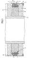
- a safety strip S is shown as a contact ring in section, which is placed around an inner tube 11.
- This contact ring has two superimposed receiving body, which are formed as contact strips 1, 2, each with contact elements 3, 4 abut each other, wherein the two contact elements 3 and 4 are formed for example by hollow rivets.
- the contact elements 3, 4 are at contact points A and B to each other.
- a piece of expander cord is inserted into the contact element 3 or 4 as a biasing element 6, which is the two receiving body, d. H.
- the contact strips 1 and 2 forces each other so that the two contact elements 3, 4 abuts each other and thus close the contact points A and B.
- the two contact strips 1 and 2 are wedge-shaped open to the outside and in this wedge space is a lsolierkeilelement 5 is inserted, which is covered to the outside by a housing wall 7.
- the contact strips 1 and 2 are in a receiving space 1, this receiving space 10 is formed by horizontally oriented wall elements 8 and 8 made of polyurethane foam, which between them include a wall element 9, which also consists of polyurethane foam, but may have a different strength than the wall elements
- the housing wall 7 terminating outwardly of the receiving space 10 consists of a relatively rigid material, so that when abutting an obstacle, this housing wall is moved inwardly towards the receiving space 10, which is possible is because the wall elements 8 and 8 can yield elastically.
- the wall element 9 forms a certain resistance, so that the Isolierkeilelement 5 can penetrate into the corresponding space between the two contact strips 1 and 2 and the contact between the contact points A and B cancels and thus causes a switching action.
- Fig. 2 shows a cutaway arrangement of an elongated safety strip S.
- the receiving body are designed as contact strips 1 and 2
- the contact elements 3 and 4 are clearly visible and in particular
- Fig. 3 shows the wedge-shaped Isolierkeilark 5, in the pressurization now the two contact strips and 2 moved apart and thereby the contact points A and B are separated from each other.
- the means for forcing the two contact strips 1 and 2 towards one another in the quiescent state are not shown in FIGS. 2 and 3, but the electrical connections between the successive contact elements.
- an electrical line 12 is provided, which may be formed in a manner belonging to the prior art.
- an electrical line 12a leads to the lower contact element 4 located on the right in the drawing, and from this representation it can be seen that the electrical line 12 lies on the upper side of the contact strip 1. that the individual contact elements are connected in series one behind the other, so that the current can flow from the contact element 3 located on the left to the contact element 3 in the middle, then passes through the contact elements 3 and 4 to the bottom of the bar 2 and here via the line 12 a Contact element 4 on the right side of the representation, from where the current then flows again to the disposed on the contact strip 1 contact element and here via the electrical connection 12 shown in the drawing to the next contact element.
- Fig. 4 shows an arrangement with two contact strips 1 and 2 and a Isolierkeilelement 5, but wherein the two contact strips 1 and 2 by a hinge member 16 fixed to each other, d. H. materially connected to each other.
- This hinge strip 16 may be formed as a film strip, so that the two contact strips 1 and 2 are easy to open and folded. But it is also possible, as shown in Fig. 4, this hinge strip 16 also form relatively large, so that thereby already the required bias of the two contact strips 1 and 2 is achieved.
- FIG. 5 shows that a circular safety strip 5, for example, six contact elements 3 and 4 may have.
- Fig. 5 which shows a plan view of the upper contact strip 1, the upper contact elements. 3 recognizable.
- an electrical lead is shown leading to the contact element 3 of the upper contact strip 1. From here leads to the right in the illustrated embodiment, an electrical line 12 to the contact element 3 of the upper contact strip 1 and from here the current through the upper contact element 3 and the lower contact element 4 to the bottom of the lower contact strip 2 flow. As shown by dashed lines at 12a, then takes place an electrical connection to the next contact element 4 of the lower contact strip 2, and from here the current through the upper contact element 3 of the upper contact strip 1 can flow upwards and gets back to an electrical line 12th
- Fig. 6 shows an annular safety strip S with the contact strips 1 and 2 and for clarity without lsolierkeilmann 5, wherein in the plan view, the upper contact elements 3 are recognizable.
- the elastic bias between the two contact strips 1 and 2 is carried out in this embodiment by pieces of hose 15, which should be clarified that the elastic bias, with which the two contact strips 1 and 2 are pressed against each other, may be formed in any manner.
- the two contact strips can be accommodated in a rubber profile hose that the profile is extruded, which in contrast to the prior art now when the insulating wedge strip such a hose is not stretched in length, but the diameter of the hose is increased.
- Fig. 7 shows in section a safety strip S with a U-shaped spring clip 101, wherein in the stirrup legs 102, 103, the contact elements 3 and 4 are housed.
- An Isolierkeilelement 104 engages with its wedge part between the wedge-shaped widening ends of the bar arms 102 and 103 and thus causes the movement apart of the contact elements 3 and 4.
- the cable lugs 105 and 106 can be seen, to which the corresponding power lines 12 and Connect 12a.
- the actual safety strip S made of metal, but can be made in the same way as a plastic molding.
Landscapes
- Push-Button Switches (AREA)
- Portable Nailing Machines And Staplers (AREA)
- Spinning Or Twisting Of Yarns (AREA)
Priority Applications (1)
| Application Number | Priority Date | Filing Date | Title |
|---|---|---|---|
| PL04727228T PL1616342T3 (pl) | 2003-04-19 | 2004-04-14 | Listwa zabezpieczająca do zabezpieczenia przed uderzeniem lub zabezpieczenia krawędzi zamykających |
Applications Claiming Priority (3)
| Application Number | Priority Date | Filing Date | Title |
|---|---|---|---|
| DE10318319 | 2003-04-19 | ||
| DE10322866A DE10322866B3 (de) | 2003-04-19 | 2003-05-21 | Sicherheitsleiste für eine Stoß- oder Schließkantensicherung |
| PCT/DE2004/000765 WO2004095486A1 (de) | 2003-04-19 | 2004-04-14 | Sicherheitsleiste für eine stoss- oder schliesskantensicherung |
Publications (2)
| Publication Number | Publication Date |
|---|---|
| EP1616342A1 EP1616342A1 (de) | 2006-01-18 |
| EP1616342B1 true EP1616342B1 (de) | 2006-12-06 |
Family
ID=33311749
Family Applications (1)
| Application Number | Title | Priority Date | Filing Date |
|---|---|---|---|
| EP04727228A Expired - Lifetime EP1616342B1 (de) | 2003-04-19 | 2004-04-14 | Sicherheitsleiste für eine stoss- oder schliesskantensicherung |
Country Status (7)
| Country | Link |
|---|---|
| US (1) | US7220928B2 (pl) |
| EP (1) | EP1616342B1 (pl) |
| AT (1) | ATE347733T1 (pl) |
| DE (1) | DE502004002240D1 (pl) |
| ES (1) | ES2277252T3 (pl) |
| PL (1) | PL1616342T3 (pl) |
| WO (1) | WO2004095486A1 (pl) |
Families Citing this family (1)
| Publication number | Priority date | Publication date | Assignee | Title |
|---|---|---|---|---|
| AU2013217184A1 (en) * | 2012-02-02 | 2014-08-21 | Tata Consultancy Services Limited | A system and method for identifying and analyzing personal context of a user |
Family Cites Families (12)
| Publication number | Priority date | Publication date | Assignee | Title |
|---|---|---|---|---|
| US3654411A (en) * | 1970-11-23 | 1972-04-04 | United Filtration Corp | Break-away switch |
| GB2080029B (en) * | 1980-07-08 | 1984-04-18 | Philips Electronic Associated | Push button switch |
| US4446342A (en) * | 1980-12-15 | 1984-05-01 | Advanced Circuit Technology | Electrical switch assembly and method of manufacture |
| US4636603A (en) * | 1984-12-03 | 1987-01-13 | Illinois Tool Works Inc. | Two-position electrical switch assembly |
| US4701582A (en) * | 1985-02-22 | 1987-10-20 | Omron Tateisi Electronics Co. | Plunger sensing switch |
| DE3606499C1 (de) | 1986-02-28 | 1987-07-16 | Werner Haake | Schliesskanten-Sicherung |
| DE19647720B4 (de) * | 1996-11-19 | 2004-05-13 | Wampfler Aktiengesellschaft | Schließkantensicherheitsleiste |
| EP0935268A3 (en) * | 1998-02-09 | 2000-09-06 | Shinmei Rubber Ind. Co., Ltd. | Omnidirectional response cable switch |
| US6198056B1 (en) * | 1999-10-12 | 2001-03-06 | General Electric Company | Electrical circuit disrupter |
| US6396010B1 (en) * | 2000-10-17 | 2002-05-28 | Matamatic, Inc. | Safety edge switch for a movable door |
| US6635834B1 (en) * | 2001-09-19 | 2003-10-21 | Justin Bernard Wenner | System and method to delay closure of a normally closed electrical circuit |
| JP2003217393A (ja) * | 2002-01-24 | 2003-07-31 | Seiko Instruments Inc | 電子機器のスイッチ |
-
2004
- 2004-04-14 ES ES04727228T patent/ES2277252T3/es not_active Expired - Lifetime
- 2004-04-14 AT AT04727228T patent/ATE347733T1/de active
- 2004-04-14 EP EP04727228A patent/EP1616342B1/de not_active Expired - Lifetime
- 2004-04-14 US US10/520,877 patent/US7220928B2/en not_active Expired - Fee Related
- 2004-04-14 WO PCT/DE2004/000765 patent/WO2004095486A1/de not_active Ceased
- 2004-04-14 PL PL04727228T patent/PL1616342T3/pl unknown
- 2004-04-14 DE DE502004002240T patent/DE502004002240D1/de not_active Expired - Lifetime
Also Published As
| Publication number | Publication date |
|---|---|
| PL1616342T3 (pl) | 2007-05-31 |
| WO2004095486A1 (de) | 2004-11-04 |
| DE502004002240D1 (de) | 2007-01-18 |
| US7220928B2 (en) | 2007-05-22 |
| US20050259367A1 (en) | 2005-11-24 |
| ES2277252T3 (es) | 2007-07-01 |
| ATE347733T1 (de) | 2006-12-15 |
| EP1616342A1 (de) | 2006-01-18 |
Similar Documents
| Publication | Publication Date | Title |
|---|---|---|
| DE3606499C1 (de) | Schliesskanten-Sicherung | |
| DE2258772C2 (de) | Aufprallsensor für ein Fahrzeug-Sicherheitssystem | |
| EP0103726B1 (de) | Sicherheitsleiste | |
| EP3132156B1 (de) | Anordnung zur aufnahme einer tragfeder eines federbeins und federteller hierzu | |
| DE102014110770A1 (de) | Lenkvorrichtung | |
| WO2012062537A1 (de) | Lenkerelement mit überlastsicherungid50000035154940 isr 2012-01-16 | |
| EP1616342B1 (de) | Sicherheitsleiste für eine stoss- oder schliesskantensicherung | |
| DE10322866B3 (de) | Sicherheitsleiste für eine Stoß- oder Schließkantensicherung | |
| DE2401918A1 (de) | Kollisionsschalter, insbesondere fuer kraftfahrzeuge | |
| DE102004015843B4 (de) | Führungseinrichtung für Rollelemente | |
| DE3883124T2 (de) | Elektrisches Massenkraftschalter. | |
| WO2005075222A1 (de) | Vorrichtung zum werkzeugfreien verstellbaren verbinden zweier kettenglieder einer geschlossenen gliederkette in unterschiedlichen abständen und/oder reparieren einer gebrochenen gliederkette | |
| WO1995026035A1 (de) | Doppeltemperatursicherung | |
| DE10144143C1 (de) | Torsionsmodul für eine Drehmomenterfassungseinrichtung | |
| DE202004018318U1 (de) | Schutzabdeckung | |
| EP1120527B1 (de) | Schaltleiste für eine Schliesskanten-Sicherung | |
| DE19946923B4 (de) | Nabenabdeckung für eine Radlagerung, vorzugsweise für eine Nutzfahrzeug-Radlagerung | |
| DE4434028C2 (de) | Türfeststeller, insbesondere für Automobile | |
| EP1633948B1 (de) | Sicherheitsleiste für eine stoss- oder schliesskantensicherung | |
| DE102006026221A1 (de) | Drehsperre | |
| DE3742273C1 (en) | Electrical contact cable | |
| DE102005040947B4 (de) | Signalgebende Schaltleiste für Sicherheitseinrichtungen | |
| EP1591609B1 (de) | Sicherheitsleiste als Schaltleiste | |
| EP1707725A2 (de) | Sicherheitsleiste als Schaltleiste | |
| DE102006011977B4 (de) | Selbstsperrender Gurtaufroller |
Legal Events
| Date | Code | Title | Description |
|---|---|---|---|
| PUAI | Public reference made under article 153(3) epc to a published international application that has entered the european phase |
Free format text: ORIGINAL CODE: 0009012 |
|
| AK | Designated contracting states |
Kind code of ref document: A1 Designated state(s): AT BE BG CH CY CZ DE DK EE ES FI FR GB GR HU IE IT LI LU MC NL PL PT RO SE SI SK TR |
|
| AX | Request for extension of the european patent |
Extension state: AL HR LT LV MK |
|
| 17P | Request for examination filed |
Effective date: 20041110 |
|
| GRAP | Despatch of communication of intention to grant a patent |
Free format text: ORIGINAL CODE: EPIDOSNIGR1 |
|
| DAX | Request for extension of the european patent (deleted) | ||
| GRAS | Grant fee paid |
Free format text: ORIGINAL CODE: EPIDOSNIGR3 |
|
| GRAA | (expected) grant |
Free format text: ORIGINAL CODE: 0009210 |
|
| AK | Designated contracting states |
Kind code of ref document: B1 Designated state(s): AT BE BG CH CY CZ DE DK EE ES FI FR GB GR HU IE IT LI LU MC NL PL PT RO SE SI SK TR |
|
| PG25 | Lapsed in a contracting state [announced via postgrant information from national office to epo] |
Ref country code: IE Free format text: LAPSE BECAUSE OF FAILURE TO SUBMIT A TRANSLATION OF THE DESCRIPTION OR TO PAY THE FEE WITHIN THE PRESCRIBED TIME-LIMIT Effective date: 20061206 Ref country code: SK Free format text: LAPSE BECAUSE OF FAILURE TO SUBMIT A TRANSLATION OF THE DESCRIPTION OR TO PAY THE FEE WITHIN THE PRESCRIBED TIME-LIMIT Effective date: 20061206 Ref country code: FI Free format text: LAPSE BECAUSE OF FAILURE TO SUBMIT A TRANSLATION OF THE DESCRIPTION OR TO PAY THE FEE WITHIN THE PRESCRIBED TIME-LIMIT Effective date: 20061206 Ref country code: SI Free format text: LAPSE BECAUSE OF FAILURE TO SUBMIT A TRANSLATION OF THE DESCRIPTION OR TO PAY THE FEE WITHIN THE PRESCRIBED TIME-LIMIT Effective date: 20061206 Ref country code: RO Free format text: LAPSE BECAUSE OF FAILURE TO SUBMIT A TRANSLATION OF THE DESCRIPTION OR TO PAY THE FEE WITHIN THE PRESCRIBED TIME-LIMIT Effective date: 20061206 Ref country code: CZ Free format text: LAPSE BECAUSE OF FAILURE TO SUBMIT A TRANSLATION OF THE DESCRIPTION OR TO PAY THE FEE WITHIN THE PRESCRIBED TIME-LIMIT Effective date: 20061206 Ref country code: DK Free format text: LAPSE BECAUSE OF FAILURE TO SUBMIT A TRANSLATION OF THE DESCRIPTION OR TO PAY THE FEE WITHIN THE PRESCRIBED TIME-LIMIT Effective date: 20061206 |
|
| REG | Reference to a national code |
Ref country code: GB Ref legal event code: FG4D Free format text: NOT ENGLISH |
|
| REG | Reference to a national code |
Ref country code: CH Ref legal event code: EP |
|
| REG | Reference to a national code |
Ref country code: IE Ref legal event code: FG4D Free format text: LANGUAGE OF EP DOCUMENT: GERMAN |
|
| REF | Corresponds to: |
Ref document number: 502004002240 Country of ref document: DE Date of ref document: 20070118 Kind code of ref document: P |
|
| PG25 | Lapsed in a contracting state [announced via postgrant information from national office to epo] |
Ref country code: BG Free format text: LAPSE BECAUSE OF FAILURE TO SUBMIT A TRANSLATION OF THE DESCRIPTION OR TO PAY THE FEE WITHIN THE PRESCRIBED TIME-LIMIT Effective date: 20070306 Ref country code: SE Free format text: LAPSE BECAUSE OF FAILURE TO SUBMIT A TRANSLATION OF THE DESCRIPTION OR TO PAY THE FEE WITHIN THE PRESCRIBED TIME-LIMIT Effective date: 20070306 |
|
| GBT | Gb: translation of ep patent filed (gb section 77(6)(a)/1977) |
Effective date: 20070214 |
|
| PG25 | Lapsed in a contracting state [announced via postgrant information from national office to epo] |
Ref country code: PT Free format text: LAPSE BECAUSE OF FAILURE TO SUBMIT A TRANSLATION OF THE DESCRIPTION OR TO PAY THE FEE WITHIN THE PRESCRIBED TIME-LIMIT Effective date: 20070507 |
|
| REG | Reference to a national code |
Ref country code: PL Ref legal event code: T3 |
|
| ET | Fr: translation filed | ||
| REG | Reference to a national code |
Ref country code: ES Ref legal event code: FG2A Ref document number: 2277252 Country of ref document: ES Kind code of ref document: T3 |
|
| PLBE | No opposition filed within time limit |
Free format text: ORIGINAL CODE: 0009261 |
|
| STAA | Information on the status of an ep patent application or granted ep patent |
Free format text: STATUS: NO OPPOSITION FILED WITHIN TIME LIMIT |
|
| 26N | No opposition filed |
Effective date: 20070907 |
|
| BERE | Be: lapsed |
Owner name: HAAKE, OLIVER Effective date: 20070430 Owner name: HAAKE, PATRICK Effective date: 20070430 Owner name: HAAKE, ANDRE Effective date: 20070430 |
|
| PG25 | Lapsed in a contracting state [announced via postgrant information from national office to epo] |
Ref country code: BE Free format text: LAPSE BECAUSE OF NON-PAYMENT OF DUE FEES Effective date: 20070430 |
|
| PG25 | Lapsed in a contracting state [announced via postgrant information from national office to epo] |
Ref country code: GR Free format text: LAPSE BECAUSE OF FAILURE TO SUBMIT A TRANSLATION OF THE DESCRIPTION OR TO PAY THE FEE WITHIN THE PRESCRIBED TIME-LIMIT Effective date: 20070307 |
|
| PG25 | Lapsed in a contracting state [announced via postgrant information from national office to epo] |
Ref country code: EE Free format text: LAPSE BECAUSE OF FAILURE TO SUBMIT A TRANSLATION OF THE DESCRIPTION OR TO PAY THE FEE WITHIN THE PRESCRIBED TIME-LIMIT Effective date: 20061206 |
|
| PG25 | Lapsed in a contracting state [announced via postgrant information from national office to epo] |
Ref country code: MC Free format text: LAPSE BECAUSE OF NON-PAYMENT OF DUE FEES Effective date: 20070430 |
|
| PG25 | Lapsed in a contracting state [announced via postgrant information from national office to epo] |
Ref country code: LU Free format text: LAPSE BECAUSE OF NON-PAYMENT OF DUE FEES Effective date: 20070414 Ref country code: CY Free format text: LAPSE BECAUSE OF FAILURE TO SUBMIT A TRANSLATION OF THE DESCRIPTION OR TO PAY THE FEE WITHIN THE PRESCRIBED TIME-LIMIT Effective date: 20061206 |
|
| PG25 | Lapsed in a contracting state [announced via postgrant information from national office to epo] |
Ref country code: TR Free format text: LAPSE BECAUSE OF FAILURE TO SUBMIT A TRANSLATION OF THE DESCRIPTION OR TO PAY THE FEE WITHIN THE PRESCRIBED TIME-LIMIT Effective date: 20061206 Ref country code: HU Free format text: LAPSE BECAUSE OF FAILURE TO SUBMIT A TRANSLATION OF THE DESCRIPTION OR TO PAY THE FEE WITHIN THE PRESCRIBED TIME-LIMIT Effective date: 20070607 |
|
| PGFP | Annual fee paid to national office [announced via postgrant information from national office to epo] |
Ref country code: ES Payment date: 20110419 Year of fee payment: 8 |
|
| PGFP | Annual fee paid to national office [announced via postgrant information from national office to epo] |
Ref country code: PL Payment date: 20110301 Year of fee payment: 8 Ref country code: NL Payment date: 20110420 Year of fee payment: 8 |
|
| PGFP | Annual fee paid to national office [announced via postgrant information from national office to epo] |
Ref country code: GB Payment date: 20120423 Year of fee payment: 9 |
|
| REG | Reference to a national code |
Ref country code: NL Ref legal event code: V1 Effective date: 20121101 |
|
| PG25 | Lapsed in a contracting state [announced via postgrant information from national office to epo] |
Ref country code: NL Free format text: LAPSE BECAUSE OF NON-PAYMENT OF DUE FEES Effective date: 20121101 |
|
| REG | Reference to a national code |
Ref country code: ES Ref legal event code: FD2A Effective date: 20130715 |
|
| PG25 | Lapsed in a contracting state [announced via postgrant information from national office to epo] |
Ref country code: ES Free format text: LAPSE BECAUSE OF NON-PAYMENT OF DUE FEES Effective date: 20120415 |
|
| PGFP | Annual fee paid to national office [announced via postgrant information from national office to epo] |
Ref country code: CH Payment date: 20130423 Year of fee payment: 10 |
|
| GBPC | Gb: european patent ceased through non-payment of renewal fee |
Effective date: 20130414 |
|
| PG25 | Lapsed in a contracting state [announced via postgrant information from national office to epo] |
Ref country code: GB Free format text: LAPSE BECAUSE OF NON-PAYMENT OF DUE FEES Effective date: 20130414 |
|
| REG | Reference to a national code |
Ref country code: PL Ref legal event code: LAPE |
|
| PG25 | Lapsed in a contracting state [announced via postgrant information from national office to epo] |
Ref country code: PL Free format text: LAPSE BECAUSE OF NON-PAYMENT OF DUE FEES Effective date: 20130414 |
|
| PGFP | Annual fee paid to national office [announced via postgrant information from national office to epo] |
Ref country code: AT Payment date: 20140417 Year of fee payment: 11 |
|
| REG | Reference to a national code |
Ref country code: CH Ref legal event code: PL |
|
| PG25 | Lapsed in a contracting state [announced via postgrant information from national office to epo] |
Ref country code: CH Free format text: LAPSE BECAUSE OF NON-PAYMENT OF DUE FEES Effective date: 20140430 Ref country code: LI Free format text: LAPSE BECAUSE OF NON-PAYMENT OF DUE FEES Effective date: 20140430 |
|
| REG | Reference to a national code |
Ref country code: AT Ref legal event code: MM01 Ref document number: 347733 Country of ref document: AT Kind code of ref document: T Effective date: 20150414 |
|
| PG25 | Lapsed in a contracting state [announced via postgrant information from national office to epo] |
Ref country code: AT Free format text: LAPSE BECAUSE OF NON-PAYMENT OF DUE FEES Effective date: 20150414 |
|
| REG | Reference to a national code |
Ref country code: FR Ref legal event code: PLFP Year of fee payment: 13 |
|
| PGFP | Annual fee paid to national office [announced via postgrant information from national office to epo] |
Ref country code: IT Payment date: 20160422 Year of fee payment: 13 Ref country code: FR Payment date: 20160422 Year of fee payment: 13 |
|
| REG | Reference to a national code |
Ref country code: FR Ref legal event code: ST Effective date: 20171229 |
|
| PG25 | Lapsed in a contracting state [announced via postgrant information from national office to epo] |
Ref country code: FR Free format text: LAPSE BECAUSE OF NON-PAYMENT OF DUE FEES Effective date: 20170502 |
|
| PG25 | Lapsed in a contracting state [announced via postgrant information from national office to epo] |
Ref country code: IT Free format text: LAPSE BECAUSE OF NON-PAYMENT OF DUE FEES Effective date: 20170414 |
|
| PGFP | Annual fee paid to national office [announced via postgrant information from national office to epo] |
Ref country code: DE Payment date: 20200219 Year of fee payment: 17 |
|
| REG | Reference to a national code |
Ref country code: DE Ref legal event code: R119 Ref document number: 502004002240 Country of ref document: DE |
|
| PG25 | Lapsed in a contracting state [announced via postgrant information from national office to epo] |
Ref country code: DE Free format text: LAPSE BECAUSE OF NON-PAYMENT OF DUE FEES Effective date: 20211103 |