EP1614980A2 - Système frigorifique - Google Patents
Système frigorifique Download PDFInfo
- Publication number
- EP1614980A2 EP1614980A2 EP20050013938 EP05013938A EP1614980A2 EP 1614980 A2 EP1614980 A2 EP 1614980A2 EP 20050013938 EP20050013938 EP 20050013938 EP 05013938 A EP05013938 A EP 05013938A EP 1614980 A2 EP1614980 A2 EP 1614980A2
- Authority
- EP
- European Patent Office
- Prior art keywords
- cold
- hot water
- heat
- heat exchanger
- thermal storage
- Prior art date
- Legal status (The legal status is an assumption and is not a legal conclusion. Google has not performed a legal analysis and makes no representation as to the accuracy of the status listed.)
- Withdrawn
Links
Images


Classifications
-
- F—MECHANICAL ENGINEERING; LIGHTING; HEATING; WEAPONS; BLASTING
- F25—REFRIGERATION OR COOLING; COMBINED HEATING AND REFRIGERATION SYSTEMS; HEAT PUMP SYSTEMS; MANUFACTURE OR STORAGE OF ICE; LIQUEFACTION SOLIDIFICATION OF GASES
- F25B—REFRIGERATION MACHINES, PLANTS OR SYSTEMS; COMBINED HEATING AND REFRIGERATION SYSTEMS; HEAT PUMP SYSTEMS
- F25B13/00—Compression machines, plants or systems, with reversible cycle
-
- F—MECHANICAL ENGINEERING; LIGHTING; HEATING; WEAPONS; BLASTING
- F25—REFRIGERATION OR COOLING; COMBINED HEATING AND REFRIGERATION SYSTEMS; HEAT PUMP SYSTEMS; MANUFACTURE OR STORAGE OF ICE; LIQUEFACTION SOLIDIFICATION OF GASES
- F25B—REFRIGERATION MACHINES, PLANTS OR SYSTEMS; COMBINED HEATING AND REFRIGERATION SYSTEMS; HEAT PUMP SYSTEMS
- F25B29/00—Combined heating and refrigeration systems, e.g. operating alternately or simultaneously
- F25B29/003—Combined heating and refrigeration systems, e.g. operating alternately or simultaneously of the compression type system
-
- F—MECHANICAL ENGINEERING; LIGHTING; HEATING; WEAPONS; BLASTING
- F25—REFRIGERATION OR COOLING; COMBINED HEATING AND REFRIGERATION SYSTEMS; HEAT PUMP SYSTEMS; MANUFACTURE OR STORAGE OF ICE; LIQUEFACTION SOLIDIFICATION OF GASES
- F25B—REFRIGERATION MACHINES, PLANTS OR SYSTEMS; COMBINED HEATING AND REFRIGERATION SYSTEMS; HEAT PUMP SYSTEMS
- F25B9/00—Compression machines, plants or systems, in which the refrigerant is air or other gas of low boiling point
- F25B9/002—Compression machines, plants or systems, in which the refrigerant is air or other gas of low boiling point characterised by the refrigerant
- F25B9/008—Compression machines, plants or systems, in which the refrigerant is air or other gas of low boiling point characterised by the refrigerant the refrigerant being carbon dioxide
-
- F—MECHANICAL ENGINEERING; LIGHTING; HEATING; WEAPONS; BLASTING
- F25—REFRIGERATION OR COOLING; COMBINED HEATING AND REFRIGERATION SYSTEMS; HEAT PUMP SYSTEMS; MANUFACTURE OR STORAGE OF ICE; LIQUEFACTION SOLIDIFICATION OF GASES
- F25B—REFRIGERATION MACHINES, PLANTS OR SYSTEMS; COMBINED HEATING AND REFRIGERATION SYSTEMS; HEAT PUMP SYSTEMS
- F25B2309/00—Gas cycle refrigeration machines
- F25B2309/06—Compression machines, plants or systems characterised by the refrigerant being carbon dioxide
- F25B2309/061—Compression machines, plants or systems characterised by the refrigerant being carbon dioxide with cycle highest pressure above the supercritical pressure
-
- F—MECHANICAL ENGINEERING; LIGHTING; HEATING; WEAPONS; BLASTING
- F25—REFRIGERATION OR COOLING; COMBINED HEATING AND REFRIGERATION SYSTEMS; HEAT PUMP SYSTEMS; MANUFACTURE OR STORAGE OF ICE; LIQUEFACTION SOLIDIFICATION OF GASES
- F25B—REFRIGERATION MACHINES, PLANTS OR SYSTEMS; COMBINED HEATING AND REFRIGERATION SYSTEMS; HEAT PUMP SYSTEMS
- F25B2400/00—General features or devices for refrigeration machines, plants or systems, combined heating and refrigeration systems or heat-pump systems, i.e. not limited to a particular subgroup of F25B
- F25B2400/22—Refrigeration systems for supermarkets
-
- F—MECHANICAL ENGINEERING; LIGHTING; HEATING; WEAPONS; BLASTING
- F25—REFRIGERATION OR COOLING; COMBINED HEATING AND REFRIGERATION SYSTEMS; HEAT PUMP SYSTEMS; MANUFACTURE OR STORAGE OF ICE; LIQUEFACTION SOLIDIFICATION OF GASES
- F25B—REFRIGERATION MACHINES, PLANTS OR SYSTEMS; COMBINED HEATING AND REFRIGERATION SYSTEMS; HEAT PUMP SYSTEMS
- F25B2400/00—General features or devices for refrigeration machines, plants or systems, combined heating and refrigeration systems or heat-pump systems, i.e. not limited to a particular subgroup of F25B
- F25B2400/24—Storage receiver heat
-
- F—MECHANICAL ENGINEERING; LIGHTING; HEATING; WEAPONS; BLASTING
- F25—REFRIGERATION OR COOLING; COMBINED HEATING AND REFRIGERATION SYSTEMS; HEAT PUMP SYSTEMS; MANUFACTURE OR STORAGE OF ICE; LIQUEFACTION SOLIDIFICATION OF GASES
- F25D—REFRIGERATORS; COLD ROOMS; ICE-BOXES; COOLING OR FREEZING APPARATUS NOT OTHERWISE PROVIDED FOR
- F25D17/00—Arrangements for circulating cooling fluids; Arrangements for circulating gas, e.g. air, within refrigerated spaces
- F25D17/02—Arrangements for circulating cooling fluids; Arrangements for circulating gas, e.g. air, within refrigerated spaces for circulating liquids, e.g. brine
Definitions
- the present invention relates to a refrigeration system, and particularly to a refrigeration systemhaving a refrigerating cycle for heat source that can be operated with nighttime power.
- the heat generated in the condenser is discharged to the outside during the thermal storage operation under which heat is thermally stored in the ice thermal storage tank, and thus the heat concerned is not effectively used.
- heat pump type hot water supply equipment also generates hot water by using as a heat source the heat generated in a condenser in a refrigerating cycle, and stores the heat of the hot water thus generated in a hot-water stocking tank.
- the heat of the condenser is also discharged to the outside during the hot-water stocking operation, and thus the heat concerned is not effectively used.
- a refrigeration system comprising: a refrigerating cycle for heat source that is operated with nighttime power and generates cold water and hot water; first and second cold/hot water thermal storage device for individually stocking hot water or cold water generated in the refrigerating cycle for heat source; a hot water supply device using the hot water stocked in the first cold/hot water thermal storage device; and an air conditioner using the cold water stocked in the second cold/hot water thermal storage device as a part of a heat source of an air-conditioning refrigerating cycle.
- a refrigerating system comprising: a refrigerating cycle for heat source including a first compressor, a first four-way valve, a first heat exchanger, a first pressure-reducing device and a second heat exchanger that are successively connected through a refrigerant pipe in this order, the first four-way valve being switched so that the first heat exchanger acts as one of a heat-radiating heat source and a heat-absorbing heat source while the second heat exchanger acts as the other heat source; a first cold/hot water thermal storage device that is connected to the first heat exchanger through a water pipe and stocks hot water when the first heat exchanger acts as the heat-radiating heat source or stocks cold water when the first heat exchanger acts as the heat-absorbing heat source; a refrigerating machine that is connected to the first cold/hot water thermal storage device and enables supercooling operation using cold water when the cold water is stocked in the first cold/hot water thermal storage device; a second cold/hot water thermal storage device that
- the air-conditioning refrigerating cycle has a bypass circuit through which refrigerant bypasses the fourth heat exchanger.
- the refrigerating machine comprises a third compressor, a condenser for heat-exchanging with the cold/hot water in the first cold/hot water thermal storage device, a third pressure-reducing device and an evaporator that are connected through a refrigerant pipe in this order.
- the refrigerating cycle for heat source is equipped with an air heat source type sixth heat exchanger between the first heat exchanger and the first pressure-reducing device.
- refrigerant with which a high-pressure side is set to supercritical pressure is filled in the refrigerating cycle for heat source.
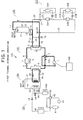
- a refrigeration system (refrigeration facilities) 100 mainly comprises a refrigerating cycle 101 for heat source which is operated with nighttime power, a first cold/hot water thermal storage device 102 constituting a so-called hot-water stocking tank, a showcase for a shop or a refrigerating machine 103 such as a large-size refrigerator/freezer 103, a second cold/hot water thermal storage device 104, and an air-conditioning refrigerating cycle 105 for air-conditioning a room to be air-conditioned.
- the refrigerating cycle 101 for heat source is constructed by successively connecting a first compressor 1, a first four-way valve 2, a first heat exchanger 3, a first pressure-reducing device 4 and a second heat exchanger 5 through a refrigerant pipe in this order, and also connecting an auxiliary pressure-reducing device 6 and an air heat source type sixth heat exchanger 7 in series between the first heat exchanger 3 and the first pressure-reducing device 4.
- Reference numeral 8 represents an air blower.
- the first heat exchanger 3 acts as a heat-radiating heat source or heat-absorbing heat source
- the second heat exchanger 5 acts as a heat-absorbing heat source or a heat-radiating heat source.
- the first cold/hot water thermal storage device 102 is connected to the showcase for the shop or the refrigerating machine 103 such as a large-size refrigerator/freezer or the like, and when cold water is stocked in the first cold/hot water thermal storage device 102, the refrigerating machine 103 is designed so that supercooling operation using the cold water concerned can be performed by the refrigerating machine 103 as described later.
- each of the refrigerating machines 103 is constructed by connecting a third compressor 21A, 21B, a condenser 22A, 22B for carrying out heat-exchange with cold/hot water of the hot-water stocking tank 11, a third pressure-reducing device 23A, 23B and an evaporator 24A, 24B through a refrigerant pipe in this order.
- Each condenser 22A, 22B is connected to a water pipe 25 in series, and the water pipe 25 is connected to the feed pipe 13.
- the water pipe 25 is connected between the feed pipe 13 and an electrically-operated three-way valve 26, and the three-way valve 26 is connected to the return pipe 17 between the other three-way valve 18 and the hot-water stocking tank 11.
- Reference numeral 27 represents a pump.
- the second cold/hot water thermal storage device 104 is equipped with a thermal storage tank 31, and water pipes 33 and 34 for circulating water or brine are connected between the thermal storage tank 31 and the second heat exchanger 5, and a pump 35 is connected to the water pipe 34.
- a pump 35 is connected to the water pipe 34.
- the air-conditioning refrigerating cycle 105 is constructed by successively connecting a second compressor 41, a second four-way valve 42, a third heat exchanger 43, a fourth heat exchanger 44 for heat-exchanging with cold/hot water of the thermal storage tank 31, a second pressure-reducing device 45, a fifth heat exchanger 46 for heat-exchanging with indoor air in the room to be air-conditioned and an accumulator 47 in this order. Furthermore, a bypass circuit 48 through which the refrigerant bypasses the fourth heat exchanger 44 is provided, and an opening and closing valve 49 is connected to the bypass circuit 48.
- Reference numeral 50 represents an opening and closing valve
- reference numeral 43A represents an air blower.
- the refrigerating cycle 105 it is possible to carry out supercooling operation or refrigerating heating operation which uses hot water, cold water and/or ice.
- any one of hot water and cold water is stocked in the hot-water stocking tank 11, and any one of hot water and ice (cold water) is stocked in the thermal storage tank 31.
- the state of the refrigerant at the outlet of the compressor 1 is represented by "a".
- the refrigerant is passed through the heat exchanger 3 and circulated, and cooled till the state a of the refrigerant is shifted to a state b while he heat of the refrigerant is radiated to water.
- the refrigerant is cooled till the state b is shifted to a state c as occasion demands.
- the refrigerant is reduced in pressure in the pressure-reducing device 4 so that the state of the refrigerant reaches a state d. Under the state d, two-phase mixture of gas/liquid refrigerant is formed.
- the above construction is provided with a controller 106 for controlling the operation of the first compressor 1 in the refrigerating cycle 101 for heat source, and the controller 106 drives the first compressor 1 in only an operating time zone for nighttime power (for example, 8:00PM - 6:00AM) in which the power consumption charge is generally set to a low value.
- a controller 106 for controlling the operation of the first compressor 1 in the refrigerating cycle 101 for heat source, and the controller 106 drives the first compressor 1 in only an operating time zone for nighttime power (for example, 8:00PM - 6:00AM) in which the power consumption charge is generally set to a low value.
- This thermal storage operation is an operation of stocking hot-water heat in the thermal storage tank 31 and also stocking cold-water heat in the hot-water stocking tank 11 as shown in Fig. 1, and it is carried out by driving the first compressor 1 of the refrigerating cycle 101 for heat source with nighttime power.
- the refrigerant discharged from the first compressor 1 is circulated through the first four-way valve 2, the second heat exchanger 5, the first pressure-reducing device 4 and the first heat exchanger 3, and then it is further passed through the first four-way valve 2 and returned to the first compressor 1 as indicated by a heavy line in Fig. 1.
- the auxiliary pressure-reducing device 6 is fully opened, and the air blower 8 is stopped.
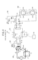
- the opening and closing valve 50 When no hot water exists in the thermal storage tank 31, the opening and closing valve 50 is closed while the opening and closing valve 49 is opened. Under this state, the refrigerant bypasses the fourth heat exchanger 44, and it is passed through the bypass pipe 48 and then circulated through the third heat exchanger 43.
Landscapes
- Engineering & Computer Science (AREA)
- Physics & Mathematics (AREA)
- Mechanical Engineering (AREA)
- Thermal Sciences (AREA)
- General Engineering & Computer Science (AREA)
- Chemical & Material Sciences (AREA)
- Chemical Kinetics & Catalysis (AREA)
- Heat-Pump Type And Storage Water Heaters (AREA)
- Compression-Type Refrigeration Machines With Reversible Cycles (AREA)
- Air Conditioning Control Device (AREA)
- Other Air-Conditioning Systems (AREA)
Applications Claiming Priority (1)
| Application Number | Priority Date | Filing Date | Title |
|---|---|---|---|
| JP2004201001A JP2006023006A (ja) | 2004-07-07 | 2004-07-07 | 冷凍設備 |
Publications (1)
| Publication Number | Publication Date |
|---|---|
| EP1614980A2 true EP1614980A2 (fr) | 2006-01-11 |
Family
ID=35241062
Family Applications (1)
| Application Number | Title | Priority Date | Filing Date |
|---|---|---|---|
| EP20050013938 Withdrawn EP1614980A2 (fr) | 2004-07-07 | 2005-06-28 | Système frigorifique |
Country Status (3)
| Country | Link |
|---|---|
| EP (1) | EP1614980A2 (fr) |
| JP (1) | JP2006023006A (fr) |
| CN (1) | CN100419349C (fr) |
Cited By (9)
| Publication number | Priority date | Publication date | Assignee | Title |
|---|---|---|---|---|
| ITMI20090331A1 (it) * | 2009-03-06 | 2010-09-07 | Ecold S N C Di Colferai Roberta & C | Impianto termico particolarmente per punti vendita di prodotti alimentari come supermercati e simili. |
| NL2003113C2 (nl) * | 2009-07-01 | 2011-01-04 | Hoogvliet B V | Warmteterugwinningseenheid, utiliteitsgebouw met warmteterugwinningseenheid, werkwijze voor het terugwinnen van warmte, gebruik van een warmtepomp. |
| CN101504210B (zh) * | 2009-03-17 | 2011-07-20 | 贝莱特空调有限公司 | 一种六合一风冷热泵机组 |
| CN103075843A (zh) * | 2013-01-21 | 2013-05-01 | 深圳市庄合地能产业科技有限公司 | 一种冷热内平衡机组 |
| EP2213962A3 (fr) * | 2009-01-28 | 2014-12-03 | SANYO Electric Co., Ltd. | Appareil de réfrigération |
| CN106765916A (zh) * | 2016-12-07 | 2017-05-31 | 郑喜勋 | 温度控制系统和温度控制方法 |
| US9765977B2 (en) | 2009-09-29 | 2017-09-19 | Mitsubishi Electric Corporation | Heat-accumulating hot-water-supplying air conditioner |
| CN107655126A (zh) * | 2017-11-01 | 2018-02-02 | 江苏高菱蓄能科技有限公司 | 一种全效水蓄冷系统 |
| DE102023202885A1 (de) | 2023-03-29 | 2024-10-02 | ECOOLTEC Grosskopf GmbH | Vorrichtung zum Temperieren eines Raums, Gas-Flüssigkeits-Wärmetauscher und Lastkraftwagen |
Families Citing this family (12)
| Publication number | Priority date | Publication date | Assignee | Title |
|---|---|---|---|---|
| JP2008241203A (ja) * | 2007-03-28 | 2008-10-09 | Toshiba Carrier Corp | ヒートポンプ冷暖房給湯機 |
| JP5585003B2 (ja) * | 2009-05-27 | 2014-09-10 | 三洋電機株式会社 | 冷凍装置 |
| JP5327308B2 (ja) * | 2011-09-30 | 2013-10-30 | ダイキン工業株式会社 | 給湯空調システム |
| JP5333557B2 (ja) * | 2011-09-30 | 2013-11-06 | ダイキン工業株式会社 | 給湯空調システム |
| JP2013104605A (ja) * | 2011-11-14 | 2013-05-30 | Panasonic Corp | 冷温水給湯装置 |
| CN102679622A (zh) * | 2012-05-22 | 2012-09-19 | 青岛大学 | 一种模块化变热容自匹配多温系统 |
| CN103090592A (zh) * | 2013-01-21 | 2013-05-08 | 深圳市庄合地能产业科技有限公司 | 一种冷热外平衡机组 |
| CN103090486A (zh) * | 2013-01-30 | 2013-05-08 | 深圳市庄合地能产业科技有限公司 | 一种热平衡一体机 |
| CN104315739B (zh) * | 2014-10-17 | 2016-09-28 | 合肥天鹅制冷科技有限公司 | 具有双冷凝双散热的冷液机 |
| CN106500399A (zh) * | 2015-09-08 | 2017-03-15 | 吴伟佳 | 一种蓄能式热泵或空调 |
| CN110857818A (zh) * | 2018-08-24 | 2020-03-03 | 约克广州空调冷冻设备有限公司 | 空调系统 |
| JP6729653B2 (ja) * | 2018-09-28 | 2020-07-22 | ダイキン工業株式会社 | 空調システム |
Family Cites Families (5)
| Publication number | Priority date | Publication date | Assignee | Title |
|---|---|---|---|---|
| JP2000179970A (ja) * | 1998-12-11 | 2000-06-30 | Sanyo Electric Co Ltd | 空気調和システム |
| JP2002081815A (ja) * | 2000-09-07 | 2002-03-22 | Sanyo Electric Co Ltd | ダクト式貯冷システム |
| JP2002089957A (ja) * | 2000-09-12 | 2002-03-27 | Sanyo Electric Co Ltd | 温水・冷水供給装置 |
| JP2003139434A (ja) * | 2001-11-06 | 2003-05-14 | Hitachi Air Conditioning System Co Ltd | 蓄熱式空調給湯システム |
| JP4062663B2 (ja) * | 2001-12-25 | 2008-03-19 | 清水建設株式会社 | 過冷却水および温水の製造システム |
-
2004
- 2004-07-07 JP JP2004201001A patent/JP2006023006A/ja not_active Withdrawn
-
2005
- 2005-04-05 CN CNB2005100628933A patent/CN100419349C/zh not_active Expired - Fee Related
- 2005-06-28 EP EP20050013938 patent/EP1614980A2/fr not_active Withdrawn
Cited By (10)
| Publication number | Priority date | Publication date | Assignee | Title |
|---|---|---|---|---|
| EP2213962A3 (fr) * | 2009-01-28 | 2014-12-03 | SANYO Electric Co., Ltd. | Appareil de réfrigération |
| ITMI20090331A1 (it) * | 2009-03-06 | 2010-09-07 | Ecold S N C Di Colferai Roberta & C | Impianto termico particolarmente per punti vendita di prodotti alimentari come supermercati e simili. |
| CN101504210B (zh) * | 2009-03-17 | 2011-07-20 | 贝莱特空调有限公司 | 一种六合一风冷热泵机组 |
| NL2003113C2 (nl) * | 2009-07-01 | 2011-01-04 | Hoogvliet B V | Warmteterugwinningseenheid, utiliteitsgebouw met warmteterugwinningseenheid, werkwijze voor het terugwinnen van warmte, gebruik van een warmtepomp. |
| US9765977B2 (en) | 2009-09-29 | 2017-09-19 | Mitsubishi Electric Corporation | Heat-accumulating hot-water-supplying air conditioner |
| CN103075843A (zh) * | 2013-01-21 | 2013-05-01 | 深圳市庄合地能产业科技有限公司 | 一种冷热内平衡机组 |
| CN106765916A (zh) * | 2016-12-07 | 2017-05-31 | 郑喜勋 | 温度控制系统和温度控制方法 |
| CN106765916B (zh) * | 2016-12-07 | 2022-09-30 | 重庆中源绿蓝能源科技有限公司 | 温度控制系统和温度控制方法 |
| CN107655126A (zh) * | 2017-11-01 | 2018-02-02 | 江苏高菱蓄能科技有限公司 | 一种全效水蓄冷系统 |
| DE102023202885A1 (de) | 2023-03-29 | 2024-10-02 | ECOOLTEC Grosskopf GmbH | Vorrichtung zum Temperieren eines Raums, Gas-Flüssigkeits-Wärmetauscher und Lastkraftwagen |
Also Published As
| Publication number | Publication date |
|---|---|
| CN100419349C (zh) | 2008-09-17 |
| CN1719159A (zh) | 2006-01-11 |
| JP2006023006A (ja) | 2006-01-26 |
Similar Documents
| Publication | Publication Date | Title |
|---|---|---|
| EP1614980A2 (fr) | Système frigorifique | |
| EP1103770B1 (fr) | Dispositif frigorifique | |
| CN103229003B (zh) | 空气调节装置 | |
| US9593872B2 (en) | Heat pump | |
| JP2894421B2 (ja) | 蓄熱式空気調和装置及び除霜方法 | |
| US9513036B2 (en) | Air-conditioning apparatus | |
| JP5383816B2 (ja) | 空気調和装置 | |
| US9353958B2 (en) | Air-conditioning apparatus | |
| US20090260389A1 (en) | Co2 refrigeration unit | |
| CN103874892B (zh) | 空气调节装置 | |
| WO2014083680A1 (fr) | Dispositif de conditionnement d'air | |
| JP5312075B2 (ja) | 二酸化炭素循環・冷却システムにおけるデフロスト装置 | |
| AU2011358039A1 (en) | Air-conditioning apparatus | |
| EP2584285B1 (fr) | Dispositif de climatisation à réfrigération | |
| US7533539B2 (en) | Refrigerating machine | |
| JP2007100987A (ja) | 冷凍システム | |
| JP4660334B2 (ja) | 冷凍システム | |
| JP5375333B2 (ja) | 自動販売機 | |
| JP2004360999A (ja) | 冷凍システム | |
| JP4488767B2 (ja) | 空調冷凍装置 | |
| JP4073375B2 (ja) | 冷凍システム及び冷凍システムの制御方法 | |
| JP2004361000A (ja) | 冷凍システム | |
| JP4073376B2 (ja) | 冷凍システム及び冷凍システムの制御方法 | |
| JP2005249242A (ja) | 空調冷凍装置 | |
| JP2004361001A (ja) | 冷凍システム |
Legal Events
| Date | Code | Title | Description |
|---|---|---|---|
| PUAI | Public reference made under article 153(3) epc to a published international application that has entered the european phase |
Free format text: ORIGINAL CODE: 0009012 |
|
| 17P | Request for examination filed |
Effective date: 20050628 |
|
| AK | Designated contracting states |
Kind code of ref document: A2 Designated state(s): AT BE BG CH CY CZ DE DK EE ES FI FR GB GR HU IE IS IT LI LT LU MC NL PL PT RO SE SI SK TR |
|
| AX | Request for extension of the european patent |
Extension state: AL BA HR LV MK YU |
|
| STAA | Information on the status of an ep patent application or granted ep patent |
Free format text: STATUS: THE APPLICATION HAS BEEN WITHDRAWN |
|
| 18W | Application withdrawn |
Effective date: 20110524 |