EP1614780A2 - Cleaning apparatus for draft roller - Google Patents
Cleaning apparatus for draft roller Download PDFInfo
- Publication number
- EP1614780A2 EP1614780A2 EP05007207A EP05007207A EP1614780A2 EP 1614780 A2 EP1614780 A2 EP 1614780A2 EP 05007207 A EP05007207 A EP 05007207A EP 05007207 A EP05007207 A EP 05007207A EP 1614780 A2 EP1614780 A2 EP 1614780A2
- Authority
- EP
- European Patent Office
- Prior art keywords
- draft roller
- roller
- holder
- scraper
- cleaning apparatus
- Prior art date
- Legal status (The legal status is an assumption and is not a legal conclusion. Google has not performed a legal analysis and makes no representation as to the accuracy of the status listed.)
- Granted
Links
Images




Classifications
-
- D—TEXTILES; PAPER
- D01—NATURAL OR MAN-MADE THREADS OR FIBRES; SPINNING
- D01H—SPINNING OR TWISTING
- D01H5/00—Drafting machines or arrangements ; Threading of roving into drafting machine
- D01H5/18—Drafting machines or arrangements without fallers or like pinned bars
- D01H5/60—Arrangements maintaining drafting elements free of fibre accumulations
- D01H5/62—Non-rotary cleaning pads or plates; Scrapers
Definitions
- the invention relates to a cleaning apparatus for a draft roller in a draft apparatus.
- Draft rollers for a draft apparatus in a spinning machine, a roving machine or the like are constituted of top rollers on the upper side and bottom rollers on the lower side. Since a sliver is drafted between the top rollers and the bottom rollers, honey dew in a case where a raw material of a sliver is cotton, an oil solution in a case where a raw material of sliver is chemical fibers or other material such as cotton fly is attached on the outer surface of a draft roller. Hence, a cleaning apparatus for removing such attachment regularly and cleaning the roller is equipped to the draft roller.
- Patent Document 1 a construction in which a belt constituted of a flexible member (a fin) is brought into contact with a draft roller to thereby slap down cotton fly or the like
- Patent Document 2 a construction in which a rubber pat is brought into contact with the outer surface of a draft roller to scratch off cotton fly or the like
- a cleaning apparatus using a belt or a rubber pat in which the belt or the rubber pat has a weak scratching force so as to contact a roller surface and rub it along tangent direction and cannot remove with certainty for cleaning.
- the apparatus using the rubber pat since the pat is regularly moved away from a roller to remove the attachment down, there has remained a problem that the attachment on the roller cannot be removed when the pat moves away.
- the invention has been made in view of the above problem and it is an object of the invention to provide a cleaning apparatus capable of removing even an attachment such as honey dew or an oil solution strongly stuck on the outer surface of a roller with certainty to thereby cleaning it.
- a cleaning apparatus for a draft roller concerning the invention is equipped with a scraper member extending in the axial direction of the draft roller, and having a sharp end edge in contact with the outer surface of the draft roller and the sharp end edge of the scraper member is brought into contact with the outer surface of the draft roller in parallel to the central axis line thereof.
- press means for pressing the scraper member against the outer surface of the draft roller in press contact therewith are provided to the cleaning apparatus.
- the cleaning apparatus is equipped with a holder member for holding the scraper member, the holder member is provided to bearing houses of the draft roller so as to be freely mounted or dismounted, and the bearing houses position the holder member.
- the bearing houses have respective holder support holes for inserting or drawing out the holding member so as to be freely mounted or dismounted, is the scraper member held so that it can freely protrude from or retreat into the holder member, has tapered portions on both ends thereof in a way such that a width increases toward the center of the holder member in a direction of inserting or drawing out of the holder member, wherein when the holder member is inserted or drawn out, a tapered portion is brought into contact with the holder support hole and the scraper member sinks in the holder member.
- the scraper member is made of synthetic resin and lower in hardness than the outer surface of the draft roller.
- a cleaning apparatus of the invention is in contact with the draft roller so that the sharp end edge of the scraper member is in parallel to the central axis line of the draft roller, honey dew, oil solution or the like attached on the outer surface of the roller is scratched off by the sharp end edge with certainty as the roller rotates.
- honey dew, oil solution or the like can be strongly scratched off under pressure from the press member. Even if the sharp end edge of the scraper member is worn more or less as time elapses, the press member can maintain a prescribed press force against the roller; therefore, unevenness in cleaning can be minimized.
- the holder member holding the scraper member or the like can be dismounted and maintenance such as adjustment of a roller gauge or exchange of scraper members can be conducted with ease by providing the holding member to the bearing house of the draft roller so as to be freely mounted or dismounted.
- the scraper member is made of synthetic resin to thereby enable a honey dew or oil solution to be scratched off with certainty with a hard characteristic of a synthetic resin. Since such a scraper is excellent in productivity and cost and softer than the metal draft roller, no damage occurs on the outer surface of the roller in a press contact with the scraper.
- a spinning machine of the embodiment has many spinning units 15, 15, ⁇ in parallel between a motor box 16 and a dust box 17.
- a spinning unit 15 includes a draft apparatus 10 having a back roller 1, a third roller 2, a second roller 3 and a front roller 4 therein and a sliver S drawn out from a sliver cans (not shown) is drafted.
- An air spinning section 11 is provided below a draft apparatus 10 and a sliver S sent out from a draft apparatus 10 is spun by the air spinning section 11.
- the spun sliver S becomes yarn Y and the yarn Y is drawn out by a yarn feed roller 12 and taken up on a take-up package 13 while being traversed.
- Back rollers 1 and third rollers 2 are, as shown in Fig. 2, constituted of top rollers 1a and 2a disposed in upper positions and bottom rollers 1 b and 2b disposed in lower positions, and a sliver S is caused to pass through between the top rollers 1 a and 2a and the bottom rollers 1 band 2b and drafted.
- a sliver S is drafted, oil solution or honey dew, or cotton fly attaches to the outer surfaces of the rollers of a draft apparatus.
- the cleaning apparatuses 5 and 5 are equipped to the lower sides of the back roller 1 and the third roller 2 for removing attachment on the bottom rollers 1 b and 2b.
- Cleaning apparatuses 5 and 5 each, as shown in Fig. 3 to 6, provide a scraper member 50, and the scraper member 50 is held by a holder member 51.
- a sharp end edge 50a is formed at the distal end of the scraper member 50, and the sharp end edge 50a is disposed so as to be in contact with the outer surface of each of the bottom rollers 1 band 2b.
- the scraper members 50 are pressed against the central axis lines 1 c and 2c of respective bottom rollers 1 band 2b by a press member 52 provided in the holder member 51, and the sharp end edge 50a of the scraper member 50 is in press contact with the outer surface of respective the bottom rollers 1b and 2b along the entire length.
- a suction member 55 is installed below the scraper member 50 and cotton fly or the like scratched off can be sucked and removed by a suction action of the suction member 55 with certainty.
- the suction member 55 is constructed so as to obtain a suction force by being connected to the dust box 17 or the like of the spinning machine.
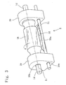
- the back bottom roller 1 b is, as shown in Fig. 3, provided with shafts 1 d and 1 d on both sides thereof.
- Bearing houses 20 and 20 are disposed on both sides of the back bottom roller 1b, and roller support holes 20b and 20b provided in the top portions of the bearing houses 20 and 20 support the shafts 1 d and 1 d and rotatably support the back bottom roller 1 b.
- Holder support holes 20a and 20a are provided in the bottom portions of the bearing houses 20, and a holder member 51 is inserted through and supported by the holder support holes 20a and 20a.
- the holder member 51 and the scraper member 50 are provided so as to extend in the axial direction of the back bottom roller 1b, and the sharp end edge 50a disposed in the axial direction of the scraper member 50 is in contact with the outer surface of a third bottom roller 2b.
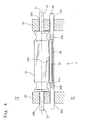
- the holder member 51 provides a housing groove 51 a in the axial direction.
- the press member 52 constituted of a leaf spring or the like is housed in the housing groove 51 a and the scraper member 50 is disposed on the press member 52.
- the press member 52 presses the scraper member 50 against the back bottom roller 1b, thereby the sharp end edge 50a of the scraper member 50 is in press contact with the outer surface of the bottom roller 1 b.
- the scraper member 50 is made of a hard synthetic resin less in deformation and adopted so as to be lower in hardness than the roller, which is an object to be cleaned. With such a construction adopted, the outer surfaces of the metal bottom rollers 1 b and 2b are not damaged physically during cleaning.
- the sharp end edge 50a of the scraper member 50 is designed so as to be constantly aligned with the central axis line 1 c of the back bottom roller 1b. That is, each of the holder support hole 20a and 20a has a sectional shape of almost an ellipse and the holder member 51 is formed so as to have a sectional shape of a polygon that can be inserted into the holder support holes 20a and 20a, and thereby, the holder member 51 inserted through the holder support holes 20a and 20a does not rotate in company with rotation of the back bottom roller 1 b and constantly assumes a position so that the sharp end edge 50a is in parallel contact with the central axis line 1c.
- the holder member 51 is constructed so as to be freely mounted to or dismounted from the bearing houses 20 and 20, whereby operations is easy in maintenance such as exchange of scraper members 50 or adjustment of a roller gauge.
- Figs. 6(a) and 6(b) are partially sectional view for describing a procedure for mounting or dismounting a holder member.
- the scraper member 50 is constructed so as to freely protrude from or retreat into the housing groove 51 a of the holder member 51 by the press member 52. Tapered sections 50b and 50b are formed on both sides of the scraper member 50.
- the holder member 51 When the holder member 51 is, as shown in Fig. 6(a), dismounted from the bearing houses 20 and 20, the holder member 51 is at first pulled in the axial direction (the direction of inserting or drawing out) C to thereby cause a tapered portion 50b of the scraper member 50 to be in contact with a hold support hole 20a. Then, the holder member 51 is further pulled in the axial direction (the direction of inserting or drawing out) C, whereby the scraper member 50 is pressed downwardly against a press force of the press member 52 and housed and sinks in the housing groove 51 a, and in this state, the holder member 51 is drawn out through the holder support hole 20a and can be dismounted.
- tapered portions 50b and 50b are formed on both ends of the scraper member 50 in a way such that a width increases toward the center of the holder member 51 in a direction of inserting or drawing out of the holder member, and the holder member 51 can be inserted into or drawn out from the holder support holes 20a smoothly on both sides of the axial direction.
- a cleaning apparatus concerning the invention can be installed in various kinds of textile machines each equipped with a draft apparatus including a spinning machine.
- the cleaning apparatus can also be applied to top rollers or the like in a draft roller.
Landscapes
- Engineering & Computer Science (AREA)
- Mechanical Engineering (AREA)
- Textile Engineering (AREA)
- Spinning Or Twisting Of Yarns (AREA)
- Cleaning In General (AREA)
Abstract
Description
- The invention relates to a cleaning apparatus for a draft roller in a draft apparatus.
- Draft rollers for a draft apparatus in a spinning machine, a roving machine or the like are constituted of top rollers on the upper side and bottom rollers on the lower side. Since a sliver is drafted between the top rollers and the bottom rollers, honey dew in a case where a raw material of a sliver is cotton, an oil solution in a case where a raw material of sliver is chemical fibers or other material such as cotton fly is attached on the outer surface of a draft roller. Hence, a cleaning apparatus for removing such attachment regularly and cleaning the roller is equipped to the draft roller. As conventional cleaning apparatuses, there have been available a construction in which a belt constituted of a flexible member (a fin) is brought into contact with a draft roller to thereby slap down cotton fly or the like (see Patent Document 1); and a construction in which a rubber pat is brought into contact with the outer surface of a draft roller to scratch off cotton fly or the like (see Patent Document 2).
- Patent Document 1: Japanese Utility Model Application Laid-open No. 6-10376
- Patent Document 2: Japanese Utility Model Registration No. 2605843
- Since a honey dew, oil solution or the like, however, has a viscosity and strongly attached on the outer surface of a roller, a cleaning apparatus using a belt or a rubber pat, in which the belt or the rubber pat has a weak scratching force so as to contact a roller surface and rub it along tangent direction and cannot remove with certainty for cleaning. In the apparatus using the rubber pat, since the pat is regularly moved away from a roller to remove the attachment down, there has remained a problem that the attachment on the roller cannot be removed when the pat moves away.
- The invention has been made in view of the above problem and it is an object of the invention to provide a cleaning apparatus capable of removing even an attachment such as honey dew or an oil solution strongly stuck on the outer surface of a roller with certainty to thereby cleaning it.
- In order to solve the problem, a cleaning apparatus for a draft roller concerning the invention is equipped with a scraper member extending in the axial direction of the draft roller, and having a sharp end edge in contact with the outer surface of the draft roller and the sharp end edge of the scraper member is brought into contact with the outer surface of the draft roller in parallel to the central axis line thereof.
- It is preferable that press means for pressing the scraper member against the outer surface of the draft roller in press contact therewith are provided to the cleaning apparatus.
- It is preferable that the cleaning apparatus is equipped with a holder member for holding the scraper member, the holder member is provided to bearing houses of the draft roller so as to be freely mounted or dismounted, and the bearing houses position the holder member.
- It is further preferable that the bearing houses have respective holder support holes for inserting or drawing out the holding member so as to be freely mounted or dismounted, is the scraper member held so that it can freely protrude from or retreat into the holder member, has tapered portions on both ends thereof in a way such that a width increases toward the center of the holder member in a direction of inserting or drawing out of the holder member, wherein when the holder member is inserted or drawn out, a tapered portion is brought into contact with the holder support hole and the scraper member sinks in the holder member.
- It is preferable that the scraper member is made of synthetic resin and lower in hardness than the outer surface of the draft roller.
- Since a cleaning apparatus of the invention is in contact with the draft roller so that the sharp end edge of the scraper member is in parallel to the central axis line of the draft roller, honey dew, oil solution or the like attached on the outer surface of the roller is scratched off by the sharp end edge with certainty as the roller rotates.
- The honey dew, oil solution or the like can be strongly scratched off under pressure from the press member. Even if the sharp end edge of the scraper member is worn more or less as time elapses, the press member can maintain a prescribed press force against the roller; therefore, unevenness in cleaning can be minimized.
- The holder member holding the scraper member or the like can be dismounted and maintenance such as adjustment of a roller gauge or exchange of scraper members can be conducted with ease by providing the holding member to the bearing house of the draft roller so as to be freely mounted or dismounted.
- The scraper member is made of synthetic resin to thereby enable a honey dew or oil solution to be scratched off with certainty with a hard characteristic of a synthetic resin. Since such a scraper is excellent in productivity and cost and softer than the metal draft roller, no damage occurs on the outer surface of the roller in a press contact with the scraper.
-
- Fig. 1 is a front view of a spinning machine equipped with a cleaning apparatus for a draft roller concerning the invention.
- Fig. 2 is a side view showing a main section of a draft apparatus equipped with a cleaning apparatus.
- Fig. 3 is a perspective, enlarged view of a section in the vicinity of a back bottom roller.
- Fig. 4 is a partially sectional view in a direction B of Fig. 2.
- Fig. 5 is a sectional view taken along a line A-A of Fig. 4.
- Figs. 6(a) and 6(b) are partially sectional views for describing a procedure for mounting or dismounting a holder member.
- Hereinafter, a cleaning apparatus for a draft roller concerning the present invention will be concretely described with referent to the drawing.
- As shown in Fig. 1, a spinning machine of the embodiment has
many spinning units motor box 16 and adust box 17. Aspinning unit 15 includes adraft apparatus 10 having aback roller 1, athird roller 2, asecond roller 3 and a front roller 4 therein and a sliver S drawn out from a sliver cans (not shown) is drafted. Anair spinning section 11 is provided below adraft apparatus 10 and a sliver S sent out from adraft apparatus 10 is spun by theair spinning section 11. The spun sliver S becomes yarn Y and the yarn Y is drawn out by ayarn feed roller 12 and taken up on a take-up package 13 while being traversed. -
Back rollers 1 andthird rollers 2 are, as shown in Fig. 2, constituted oftop rollers 1a and 2a disposed in upper positions andbottom rollers top rollers 1 a and 2a and thebottom rollers 1band 2b and drafted. When a sliver S is drafted, oil solution or honey dew, or cotton fly attaches to the outer surfaces of the rollers of a draft apparatus. Hence, thecleaning apparatuses back roller 1 and thethird roller 2 for removing attachment on thebottom rollers -
Cleaning apparatuses scraper member 50, and thescraper member 50 is held by aholder member 51. Asharp end edge 50a is formed at the distal end of thescraper member 50, and thesharp end edge 50a is disposed so as to be in contact with the outer surface of each of thebottom rollers 1band 2b. Thescraper members 50 are pressed against thecentral axis lines respective bottom rollers 1band 2b by apress member 52 provided in theholder member 51, and thesharp end edge 50a of thescraper member 50 is in press contact with the outer surface of respective thebottom rollers - Since the outer surface of each of the
bottom rollers sharp end edge 50a of thescraper member 50, thesharp end edge 50a scratches off attachment such as honey dew attached on the outer surface of each of thebottom rollers bottom rollers suction member 55 is installed below thescraper member 50 and cotton fly or the like scratched off can be sucked and removed by a suction action of thesuction member 55 with certainty. Thesuction member 55 is constructed so as to obtain a suction force by being connected to thedust box 17 or the like of the spinning machine. - The
back bottom roller 1 b is, as shown in Fig. 3, provided withshafts houses back bottom roller 1b, androller support holes bearing houses shafts back bottom roller 1 b. Holder supportholes bearing houses 20, and aholder member 51 is inserted through and supported by theholder support holes - The
holder member 51 and thescraper member 50 are provided so as to extend in the axial direction of theback bottom roller 1b, and thesharp end edge 50a disposed in the axial direction of thescraper member 50 is in contact with the outer surface of athird bottom roller 2b. As shown in Fig. 4, theholder member 51 provides ahousing groove 51 a in the axial direction. Thepress member 52 constituted of a leaf spring or the like is housed in thehousing groove 51 a and thescraper member 50 is disposed on thepress member 52. Thepress member 52 presses thescraper member 50 against theback bottom roller 1b, thereby thesharp end edge 50a of thescraper member 50 is in press contact with the outer surface of thebottom roller 1 b. For example, thescraper member 50 is made of a hard synthetic resin less in deformation and adopted so as to be lower in hardness than the roller, which is an object to be cleaned. With such a construction adopted, the outer surfaces of themetal bottom rollers - In order to improve a scratching force on the outer surface of a roller, the
sharp end edge 50a of thescraper member 50 is designed so as to be constantly aligned with thecentral axis line 1 c of theback bottom roller 1b. That is, each of theholder support hole holder member 51 is formed so as to have a sectional shape of a polygon that can be inserted into theholder support holes holder member 51 inserted through theholder support holes back bottom roller 1 b and constantly assumes a position so that thesharp end edge 50a is in parallel contact with thecentral axis line 1c. - In a case of
Patent Document 2, conventionally, there has been a problem that a rubber pat or a belt is an obstacle in adjustment of a roller gauge. Therefore, theholder member 51 is constructed so as to be freely mounted to or dismounted from the bearinghouses scraper members 50 or adjustment of a roller gauge. Figs. 6(a) and 6(b) are partially sectional view for describing a procedure for mounting or dismounting a holder member. As shown in Fig. 4, thescraper member 50 is constructed so as to freely protrude from or retreat into thehousing groove 51 a of theholder member 51 by thepress member 52. Taperedsections scraper member 50. When theholder member 51 is, as shown in Fig. 6(a), dismounted from thebearing houses holder member 51 is at first pulled in the axial direction (the direction of inserting or drawing out) C to thereby cause atapered portion 50b of thescraper member 50 to be in contact with ahold support hole 20a. Then, theholder member 51 is further pulled in the axial direction (the direction of inserting or drawing out) C, whereby thescraper member 50 is pressed downwardly against a press force of thepress member 52 and housed and sinks in thehousing groove 51 a, and in this state, theholder member 51 is drawn out through theholder support hole 20a and can be dismounted. That is, taperedportions scraper member 50 in a way such that a width increases toward the center of theholder member 51 in a direction of inserting or drawing out of the holder member, and theholder member 51 can be inserted into or drawn out from theholder support holes 20a smoothly on both sides of the axial direction. - A cleaning apparatus concerning the invention can be installed in various kinds of textile machines each equipped with a draft apparatus including a spinning machine. The cleaning apparatus can also be applied to top rollers or the like in a draft roller.
Claims (5)
- A cleaning apparatus for a draft roller, characterized in that a scraper member extending in the axial direction of the draft roller and having a sharp end edge in contact with the outer surface of the draft roller is equipped, the sharp end edge of the scraper member is brought into contact with the outer surface of the draft roller in parallel to the central axis line thereof.
- A cleaning apparatus for a draft roller as claimed in claim 1, characterized in that press means for pressing said scraper member against the outer surface of the draft roller in press contact therewith is provided.
- A cleaning apparatus for a draft roller as claimed in claim 1 or 2, characterized in that a holder member for holding the scraper member is provided, the holder member is provided to bearing houses of the draft roller so as to be freely mounted or dismounted, and the bearing houses position the holder member.
- A cleaning apparatus for a draft roller as claimed in claim 3, characterized in that the bearing houses have respective holder support holes for inserting or drawing out the holding member so as to be freely mounted or dismounted, is the scraper member held so that it can freely protrude from or retreat into the holder member, and has tapered portions on both ends thereof in a way such that a width increases toward the center of the holder member in a direction of inserting or drawing out of the holder member, wherein when the holder member is inserted or drawn out, a tapered portion is brought into contact with the holder support hole and the scraper member sinks in the holder member.
- A cleaning apparatus for a draft roller as claimed in any of claims 1 to 4, characterized in that the scraper member is made of synthetic resin and lower in hardness than the outer surface of the draft roller.
Applications Claiming Priority (1)
| Application Number | Priority Date | Filing Date | Title |
|---|---|---|---|
| JP2004202618A JP4379599B2 (en) | 2004-07-09 | 2004-07-09 | Draft roller cleaning device |
Publications (3)
| Publication Number | Publication Date |
|---|---|
| EP1614780A2 true EP1614780A2 (en) | 2006-01-11 |
| EP1614780A3 EP1614780A3 (en) | 2006-11-02 |
| EP1614780B1 EP1614780B1 (en) | 2012-06-13 |
Family
ID=35169544
Family Applications (1)
| Application Number | Title | Priority Date | Filing Date |
|---|---|---|---|
| EP20050007207 Expired - Lifetime EP1614780B1 (en) | 2004-07-09 | 2005-04-01 | Cleaning apparatus for draft roller |
Country Status (3)
| Country | Link |
|---|---|
| EP (1) | EP1614780B1 (en) |
| JP (1) | JP4379599B2 (en) |
| CN (1) | CN1718878B (en) |
Cited By (4)
| Publication number | Priority date | Publication date | Assignee | Title |
|---|---|---|---|---|
| CN102652191A (en) * | 2009-12-16 | 2012-08-29 | 村田机械株式会社 | Draft machine and roller unit |
| EP3260585A1 (en) * | 2016-06-24 | 2017-12-27 | Murata Machinery, Ltd. | Cleaning device for drafting roller |
| CN110965158A (en) * | 2019-11-25 | 2020-04-07 | 张家港市澳源毛条有限公司 | An improved cleaning device for the top drafting roller in the sliver making machine |
| CN114016171A (en) * | 2021-11-19 | 2022-02-08 | 浙江金元亚麻有限公司 | Independent cleaning device and method for drafting shaft of flax drawing frame |
Families Citing this family (12)
| Publication number | Priority date | Publication date | Assignee | Title |
|---|---|---|---|---|
| DE102011113367A1 (en) * | 2011-09-15 | 2013-03-21 | Trützschler GmbH & Co Kommanditgesellschaft | Device on a spinning preparation machine, in particular track, carding machine, combing machine or the like. with a drafting system |
| JP2013067871A (en) | 2011-09-20 | 2013-04-18 | Murata Mach Ltd | Draft device and spinning machine |
| CN102433616A (en) * | 2011-10-09 | 2012-05-02 | 常熟市威腾进出口有限公司 | Textile hook roller safety protection device |
| JP2014009404A (en) * | 2012-06-27 | 2014-01-20 | Murata Mach Ltd | Cleaning device, draft machine and spinning machine of draft roller |
| JP2015101797A (en) | 2013-11-21 | 2015-06-04 | 村田機械株式会社 | Cleaning device, draft device and spinning unit |
| CN108035066A (en) * | 2017-12-15 | 2018-05-15 | 新昌县开心纺织有限公司 | A kind of man-made fur knitting machine roller device |
| CN109049985A (en) * | 2018-09-19 | 2018-12-21 | 武汉易制科技有限公司 | A kind of automatic cleaning apparatus of inkjet style printer piezoelectric type spray head |
| CN111441143A (en) * | 2019-01-17 | 2020-07-24 | 天津市奥丰地毯有限公司 | Stable thread feeding and tightening equipment for carpet gun embroidery machine |
| CN111101247A (en) * | 2019-11-15 | 2020-05-05 | 西安优信机电工程有限公司 | A kind of spacer gauge for insert type spinning cleaning |
| DE102020132058A1 (en) * | 2020-12-02 | 2022-06-02 | Maschinenfabrik Rieter Ag | Elastic cleaning lip, support element and cleaning device |
| CN114808208B (en) * | 2022-05-06 | 2023-04-11 | 巢湖市春维纺织有限公司 | Environment-friendly air flow spinning machine |
| CN118854501B (en) * | 2024-07-26 | 2026-05-01 | 杭州凤谊纺织有限公司 | Auto-leveling drawing frame |
Family Cites Families (17)
| Publication number | Priority date | Publication date | Assignee | Title |
|---|---|---|---|---|
| GB476514A (en) * | 1936-07-17 | 1937-12-10 | J & T M Greeves Ltd | Improvements in the rubbers or clearers for the pressing rollers of machines used in the drawing of flax and other fibres for forming slivers or yarn |
| US3101504A (en) * | 1959-09-12 | 1963-08-27 | Luwa Ag | Cleaning device for yarn carrying rotary cylinders of textile machines |
| FR2145411B1 (en) * | 1969-12-05 | 1974-03-29 | Sant Andrea Novara Officine | |
| JPS5455919U (en) * | 1977-09-20 | 1979-04-18 | ||
| IT8053458U1 (en) * | 1980-08-04 | 1982-02-04 | Hotz Hans Rudolf | CLEANING DEVICE FOR CYLINDERS OF TEXTILE MACHINERY IRONING MILLS. |
| CH659088A5 (en) * | 1983-06-20 | 1986-12-31 | Galipag | SCRAPER FOR THE CYLINDER OF TEXTILE MACHINES. |
| JPS60246827A (en) * | 1984-05-21 | 1985-12-06 | Kanai Hiroyuki | Apparatus for intermittent driving of clearer for draft roller of spinning frame |
| JPH0657891B2 (en) * | 1986-02-14 | 1994-08-03 | 豊和工業株式会社 | Spinning machine drafting equipment |
| JPH0426460Y2 (en) * | 1986-12-25 | 1992-06-25 | ||
| JPH0740528Y2 (en) * | 1989-07-13 | 1995-09-20 | 陽司 北村 | Pad type clearer clearer material |
| CH681459A5 (en) * | 1990-01-19 | 1993-03-31 | Rieter Ag Maschf | |
| JP2633771B2 (en) * | 1991-07-05 | 1997-07-23 | 陽司 北村 | Plate-shaped clearer and clearer device |
| JPH064080U (en) * | 1992-06-10 | 1994-01-18 | 豊和工業株式会社 | Spinning machine new muffler |
| JPH0610376U (en) * | 1992-07-10 | 1994-02-08 | 村田機械株式会社 | Draft device cleaning device |
| JP2605843Y2 (en) * | 1993-09-06 | 2000-08-21 | 村田機械株式会社 | Draft roller cleaning device |
| CN2334768Y (en) * | 1998-05-11 | 1999-08-25 | 李鹤松 | The Automatic Cleaning Device of the Upper Cot Roller Behind the Pressing Arm of the Spinning Frame |
| CN2666940Y (en) * | 2003-11-21 | 2004-12-29 | 东台纺织机械有限责任公司 | Rover roller cleaning device |
-
2004
- 2004-07-09 JP JP2004202618A patent/JP4379599B2/en not_active Expired - Lifetime
-
2005
- 2005-04-01 EP EP20050007207 patent/EP1614780B1/en not_active Expired - Lifetime
- 2005-07-08 CN CN 200510083546 patent/CN1718878B/en not_active Expired - Fee Related
Cited By (5)
| Publication number | Priority date | Publication date | Assignee | Title |
|---|---|---|---|---|
| CN102652191A (en) * | 2009-12-16 | 2012-08-29 | 村田机械株式会社 | Draft machine and roller unit |
| CN102652191B (en) * | 2009-12-16 | 2014-11-26 | 村田机械株式会社 | Draft machine and roller unit |
| EP3260585A1 (en) * | 2016-06-24 | 2017-12-27 | Murata Machinery, Ltd. | Cleaning device for drafting roller |
| CN110965158A (en) * | 2019-11-25 | 2020-04-07 | 张家港市澳源毛条有限公司 | An improved cleaning device for the top drafting roller in the sliver making machine |
| CN114016171A (en) * | 2021-11-19 | 2022-02-08 | 浙江金元亚麻有限公司 | Independent cleaning device and method for drafting shaft of flax drawing frame |
Also Published As
| Publication number | Publication date |
|---|---|
| CN1718878B (en) | 2011-01-12 |
| CN1718878A (en) | 2006-01-11 |
| EP1614780B1 (en) | 2012-06-13 |
| EP1614780A3 (en) | 2006-11-02 |
| JP2006022443A (en) | 2006-01-26 |
| JP4379599B2 (en) | 2009-12-09 |
Similar Documents
| Publication | Publication Date | Title |
|---|---|---|
| EP1614780B1 (en) | Cleaning apparatus for draft roller | |
| KR101460481B1 (en) | Module Type Automatic Filter Exchanging Apparatus | |
| JP2015036456A (en) | Cleaning device for fiber bundle delivery device in pre-spinning machine | |
| EP2876193A1 (en) | Cleaning device, drafting device, and spinning unit | |
| CN100415964C (en) | Fiber Bundle Concentrating Devices in Spinning Machinery | |
| CN102652191B (en) | Draft machine and roller unit | |
| JP2009013550A (en) | Cleaner for draft rollers, draft device, and textile machine | |
| JP2009068126A (en) | Cleaner for draft roller, draft device, and textile machine | |
| EP0900864A2 (en) | Cleaner for roving apparatus | |
| CN218554849U (en) | Laminating roller with paper dirt cleaning device | |
| CN207987396U (en) | The cleaning device of carry-over pinch rolls | |
| KR20100019911A (en) | Apparatus for cleaning conveyor belt | |
| CN107962004B (en) | Paper dust collector | |
| CN212797703U (en) | Bobbin storage device | |
| WO2011045896A1 (en) | Panel cleaning apparatus and panel cleaning method | |
| JPS63303130A (en) | Bottom epron cradle apparatus for spinning frame | |
| CN220767271U (en) | Impurity removing device for cotton dripping plate of carding machine | |
| CN1185493A (en) | Device for keeping clean of texitile fiber material conveying roller in machine | |
| CN216330988U (en) | Cleaning rubber roller in preceding-stage counter-pressure roller assembly for thermal transfer printer | |
| US2391754A (en) | Roll cleaning apparatus for spinning frames and the like | |
| CN201003089Y (en) | Two-for-one twister friction disk filth-separation device | |
| US3541630A (en) | Roll clearing | |
| JPH0719367U (en) | Draft roller cleaning device | |
| JP2515697Y2 (en) | Receiving device in collector device of spinning machine | |
| JP3473159B2 (en) | Support structure of pneumatic nozzle in spinning machine and supporting member |
Legal Events
| Date | Code | Title | Description |
|---|---|---|---|
| PUAI | Public reference made under article 153(3) epc to a published international application that has entered the european phase |
Free format text: ORIGINAL CODE: 0009012 |
|
| AK | Designated contracting states |
Kind code of ref document: A2 Designated state(s): AT BE BG CH CY CZ DE DK EE ES FI FR GB GR HU IE IS IT LI LT LU MC NL PL PT RO SE SI SK TR |
|
| AX | Request for extension of the european patent |
Extension state: AL BA HR LV MK YU |
|
| PUAL | Search report despatched |
Free format text: ORIGINAL CODE: 0009013 |
|
| AK | Designated contracting states |
Kind code of ref document: A3 Designated state(s): AT BE BG CH CY CZ DE DK EE ES FI FR GB GR HU IE IS IT LI LT LU MC NL PL PT RO SE SI SK TR |
|
| AX | Request for extension of the european patent |
Extension state: AL BA HR LV MK YU |
|
| 17P | Request for examination filed |
Effective date: 20070103 |
|
| AKX | Designation fees paid |
Designated state(s): CH DE LI TR |
|
| 17Q | First examination report despatched |
Effective date: 20080304 |
|
| GRAP | Despatch of communication of intention to grant a patent |
Free format text: ORIGINAL CODE: EPIDOSNIGR1 |
|
| GRAS | Grant fee paid |
Free format text: ORIGINAL CODE: EPIDOSNIGR3 |
|
| GRAA | (expected) grant |
Free format text: ORIGINAL CODE: 0009210 |
|
| AK | Designated contracting states |
Kind code of ref document: B1 Designated state(s): CH DE LI TR |
|
| REG | Reference to a national code |
Ref country code: CH Ref legal event code: EP |
|
| REG | Reference to a national code |
Ref country code: DE Ref legal event code: R096 Ref document number: 602005034617 Country of ref document: DE Effective date: 20120809 |
|
| PLBE | No opposition filed within time limit |
Free format text: ORIGINAL CODE: 0009261 |
|
| STAA | Information on the status of an ep patent application or granted ep patent |
Free format text: STATUS: NO OPPOSITION FILED WITHIN TIME LIMIT |
|
| 26N | No opposition filed |
Effective date: 20130314 |
|
| REG | Reference to a national code |
Ref country code: DE Ref legal event code: R097 Ref document number: 602005034617 Country of ref document: DE Effective date: 20130314 |
|
| PG25 | Lapsed in a contracting state [announced via postgrant information from national office to epo] |
Ref country code: DE Free format text: LAPSE BECAUSE OF NON-PAYMENT OF DUE FEES Effective date: 20131101 |
|
| REG | Reference to a national code |
Ref country code: DE Ref legal event code: R119 Ref document number: 602005034617 Country of ref document: DE Effective date: 20131101 |
|
| PG25 | Lapsed in a contracting state [announced via postgrant information from national office to epo] |
Ref country code: TR Free format text: LAPSE BECAUSE OF FAILURE TO SUBMIT A TRANSLATION OF THE DESCRIPTION OR TO PAY THE FEE WITHIN THE PRESCRIBED TIME-LIMIT Effective date: 20120613 |
|
| PGFP | Annual fee paid to national office [announced via postgrant information from national office to epo] |
Ref country code: CH Payment date: 20190418 Year of fee payment: 15 |
|
| REG | Reference to a national code |
Ref country code: CH Ref legal event code: PL |
|
| PG25 | Lapsed in a contracting state [announced via postgrant information from national office to epo] |
Ref country code: CH Free format text: LAPSE BECAUSE OF NON-PAYMENT OF DUE FEES Effective date: 20200430 Ref country code: LI Free format text: LAPSE BECAUSE OF NON-PAYMENT OF DUE FEES Effective date: 20200430 |