EP1614552B1 - Brückenförmige Halterung für elektromechanische Wandler in Reifen - Google Patents
Brückenförmige Halterung für elektromechanische Wandler in Reifen Download PDFInfo
- Publication number
- EP1614552B1 EP1614552B1 EP05014765A EP05014765A EP1614552B1 EP 1614552 B1 EP1614552 B1 EP 1614552B1 EP 05014765 A EP05014765 A EP 05014765A EP 05014765 A EP05014765 A EP 05014765A EP 1614552 B1 EP1614552 B1 EP 1614552B1
- Authority
- EP
- European Patent Office
- Prior art keywords
- tire
- pad
- bridge member
- bridge
- set forth
- Prior art date
- Legal status (The legal status is an assumption and is not a legal conclusion. Google has not performed a legal analysis and makes no representation as to the accuracy of the status listed.)
- Expired - Lifetime
Links
Images


Classifications
-
- B—PERFORMING OPERATIONS; TRANSPORTING
- B60—VEHICLES IN GENERAL
- B60C—VEHICLE TYRES; TYRE INFLATION; TYRE CHANGING; CONNECTING VALVES TO INFLATABLE ELASTIC BODIES IN GENERAL; DEVICES OR ARRANGEMENTS RELATED TO TYRES
- B60C23/00—Devices for measuring, signalling, controlling, or distributing tyre pressure or temperature, specially adapted for mounting on vehicles; Arrangement of tyre inflating devices on vehicles, e.g. of pumps or of tanks; Tyre cooling arrangements
- B60C23/02—Signalling devices actuated by tyre pressure
- B60C23/04—Signalling devices actuated by tyre pressure mounted on the wheel or tyre
- B60C23/0491—Constructional details of means for attaching the control device
- B60C23/0493—Constructional details of means for attaching the control device for attachment on the tyre
Definitions
- the present invention relates generally to a bridge patch attached to the inner liner of a tire that carries an electrical circuit with an electromechanical transducer element.
- the bridge patch is configured to impart mechanical forces to the electromechanical transducer element in a predetermined fashion when the tire experiences deformation.
- DE 102 55 138 A1 discloses a tire assembly comprising a tire having an inner liner on which a mounting patch is attached.
- an electromechanical transducer element such as a piezo element
- the electromechanical transducer element converts forces imparted thereon into electrical power for use in running the electrical circuit.
- DE 195 22 269 A1 discloses a piezo-electric element being incorporated into a body member forming a space underneath said element. The body member is attached to the inner liner of a tire. The piezo-electric element generates a pulse-like signal for counting the revolutions of the tire.
- One way of imparting forces to the electromechanical transducer element resides in utilizing tire deformation during vehicle operation.
- Deformation in the tire may produce, for example, a strain field of up to 50,000 microstrain that can be converted into electrical energy.
- subjecting the electromechanical transducer element to this amount of strain may cause the element to break if, for instance, the optimum peak strain of the element is 3000 microstrain.
- the present invention provides a bridge patch for supporting electronics, including an electromechanical transducer element, within a tire.
- one or more pads are configured for attachment to, or integration with, the inner liner of a tire and provide support to a bridge member that is attached to the pad but separated from the inner liner.
- Various parameters in the construction of the bridge member and pads may be altered to impart a particular and desired stress-strain relationship to the electromechanical transducer element during tire operation. As such, the amount and direction of forces applied to the electromechanical transducer element are controlled in a manner that protects the element from excessive force while applying the amount necessary to power associated electronics.
- the bridge patch of the present invention can have a variety of configurations.
- the bridge member may be either substantially straight or arch-shaped.
- arch-shaped the bridge member may be arranged so that it is either concave or convex with respect to the inner liner of the tire.
- One or more supporting rails may also be located on the bridge member for increasing the stiffness of the bridge member if desired.
- one or more ends of the bridge member may be cylindrical in shape in order to form a larger surface area at the point connection to the pad.
- the present invention provides a tire assembly that includes a tire having an inner liner.
- a first pad and a second pad are attached to the inner liner of the tire and are separated from one another by a predetermined distance.
- a bridge member is provided that has at least two ends. On end is attached to the first pad, the another end attached to the second pad. The bridge member is separated from contact with the tire.
- An electromechanical transducer element is attached to the bridge member and is configured with the first and second pads so as to control the mechanical energy imparted to the electromechanical transducer element as a result of the deformation of the inner liner during operation of the tire.
- the present invention provides a bridge patch assembly for use with a tire having an inner liner.
- the assembly includes at least one pad configured for placement upon the inner liner of the tire.
- a bridge member is attached to the pad and configured to be separated from contact with the tire when the pad is attached to the tire.
- An electromechanical transducer element is located upon the bridge member and is configured for converting mechanical energy from deformation of the tire into electrical energy.
- the pad may consist of a single pad to which the bridge member is attached. Alternatively, three pads may be provided, including a first pad, a second pad, and a third pad. As such, the third pad is located substantially between the first pad and the second pad.
- the bridge member is attached to the first pad and the second pad; at least one connecting element is attached to the third pad and the bridge member so as to further constrain the movement of the bridge member during use of the bridge patch with the tire.
- the patch may be attached to the inner liner of a tire so that a chamber is formed having an interior space defined by the bridge member, the single pad, and the inner liner of the tire.
- the interior space may be fluidly sealed from the remaining interior space of the tire or, an aperture may be created to provide fluid communication with the interior space so defined.
- the bridge member may be arched, substantially flat, or other shapes may be used. When arch-shaped, the bridge member may arch towards or away from the inner liner of the tire. To help reduce stress concentrations, the bridge member may include rolled or cylindrically-shaped ends where connected to the pad. One or more rails may be included with the bridge member to increase its stiffness.
- the present invention also provides a method for obtaining a desired stress-strain relationship on an electromechanical transducer element.
- a method of the present invention includes providing a tire having a pair of pads located on the inner liner of the tire, bridging the pads with a bridge member such that the bridge member is separated from contact with the inner liner of the tire, and attaching an electromechanical transducer element to the bridge member.
- An additional step of sizing the thickness of the bridge member in order to provide the desired stress-strain relationship on the electromechanical transducer element during tire operation may be included.
- this method may include a step of sizing the width of the bridge member in order to provide the desired stress-strain relationship on the electromechanical transducer element during tire operation.
- a step of spacing the bridge member from the inner liner of the tire in order to provide the desired stress-strain relationship on the electromechanical transducer element during tire operation may also be added.
- a step may be included for selecting a material for the bridge member such that the material has a modulus of elasticity that contributes to creating the desired stress-strain relationship on the electromechanical transducer element during tire operation.
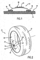
- Figure 1 is a cross-sectional view of an exemplary embodiment of abridge patch taken along line 1-1 of Fig. 2 .
- Figure 2 is a perspective view of a tire assembly incorporating the exemplary embodiment of Fig. 1 .
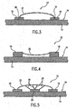
- Figure 3 is a cross-sectional view of an exemplary embodiment of a bridge patch with a pair of cylindrically-shaped ends.
- Figure 4 is a cross-sectional view of another exemplary embodiment of a bridge patch arching towards the tire surface.
- Figure 5 is a cross-aectional view of an exemplary embodiment of a bridge patch having a plurality of connecting elements and a third pad.
- Figure 6 is a cross-sectional view taken along line of 6-6 of Fig. 7 .
- Figure 7 is a perspective view of an exemplary embodiment of a bridge patch without an arch shape.
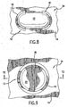
- Figure 8 is a plan view of an exemplary embodiment of a bridge patch with arch-shaped pads.
- Figure 9 is a plan view of an exemplary embodiment of a bridge patch with a single pad.
- Figure 10 is a cross-sectional view taken along line 10-10 of Fig. 9 .
- Figure 11 is a perspective view of an exemplary embodiment of a bridge patch with a single pad having a passageway defined therethrough.
- Figs. 1 and 2 illustrate an exemplary embodiment of a bridge patch 12 of the present invention attached to inner liner 34 of a tire 14.
- Fig. 1 provides a cross-sectional view of patch 12 while
- Fig. 2 shows a tire assembly 10 with bridge patch 12 attached to the inner liner 34 of tire 14.
- bridge patch 12 may be located at a variety of other positions and orientations with respect to tire 14.
- a pair of pads 16 and 18 are attached to the inner liner 34, and an arch-shaped bridge member 22 is attached on either end to pads 16 and 18.
- An electrical circuit 24 that includes an electromechanical transducer element 26, such as a piezo element, is attached to the bridge member 22.
- the bridge member 22 is thus suspended over and does not contact the inner liner 34.
- the electromechanical transducer element 26 may require a different stress-strain relationship from that imparted to the inner liner 34 during operation of tire 14.
- the desired stress-strain relationship for transducer element 26 can be created through placement of transducer element 26 onto bridge patch 12. More specifically, bridge patch 12 and pads 16 and 18 can be configured to convert the stress-strain relationship imparted by deformation of the inner liner 34 into the desired stress-strain relationship for the electromechanical transducer element 26.
- bridge member 22 is configured into an arch-shape between pads 16 and 18.
- This configuration can be used to reduce the magnitude of the stress-strain relationship the electromechanical transducer element 26 would otherwise experience if it were attached directly to inner liner 34.
- the materials used in the construction ofpads 16 and 18 can also allow for a reduction in the stress-strain experienced by transducer element 26 by operating to absorb or deflect part of the stress-strain that occurs during deformation of inner liner 34.
- Figs. 1 and 2 are provided by way of example of the present invention.
- bridge patch 12 may also be used to redirect the stress-strain relationship in order to accommodate a desired orientation of the stress-strain relationship on the electromechanical transducer element 26.
- the bridge patch 12 may be configured so that the magnitude and orientation of the stress-strain relationship is uniform across the entire bridge member 22.
- the bridge patch 12 may be configured so that the magnitude and orientation of the stress-strain relationship is different at various locations on the bridge member 22.
- various elements of the construction of the bridge patch 12 can be altered to provide the desired result.
- the width, thickness, shape and/or modulus of elasticity of the bridge member 22 or pads 16 and 18 may be varied to obtain the desired stress-strain relationship for the electromechanical transducer element 26.
- the distance separating the inner liner 34 from the bridge member 22 may also be varied in order to help obtain the desired stress-strain relationship.
- various parameters may be adjusted in order to transform the stress-strain relationship of the inner liner 34 into the desired stress-strain for bridge patch 12.
- Various exemplary embodiments of the bridge patch 12 will now be discussed in greater detail.
- bridge patch 12 may be alternatively configured so that bridge member 22 is arched in and towards inner liner 34.
- the electromechanical transducer element 26 maybe attached to either side of the bridge member 22 depending upon the stress-strain relationship desired during operation of tire 14.
- bridge patch 12 may be configured as shown in Fig. 5 .
- an additional pad 20 is attached to the: inner liner 34 and is located between pads 16 and 18.
- One or more connecting elements 28 may be attached to both pad 20 and bridge member 22. The connecting elements 28 stiffen the bridge member 22 and help obtain the desired stress-strain relationship.
- bridge member 22 may also be configured to be substantially straight, as shown in Figs. 6 and 7 .
- Bridge member 22 may be provided with one or more supporting rails 32 in order to help stiffen bridge member 22 and subsequently produce the desired stress-strain relationship.
- Supporting rails 32 may be provided in any number, thickness, cross-sectional shape, or size in order to achieve a desired stiffness of bridge member 22.
- pads 16 and 18 may be configured in order to help obtain the desired stress-strain relationship.
- the thickness, shape, or materials of construction selected for pads 16 and 18 can be varied in order to help obtain the desired stress-strain relationship on bridge member 22.
- Fig. 8 shows a configuration where the pads 16 and 18 are arch-shaped, instead of being simply rectangular as shown in other exemplary embodiments.
- bridge patch 12 can be configured so that only a single pad 16 is present.
- Fig. 9 shows one such exemplary embodiment where the perimeter of bridge member 22 is attached to a single pad 16.
- This arrangement of bridge patch 12 causes tire 14, pad 16, and bridge member 22 to define an interior space 36 as shown in Fig. 10 .
- Interior space 36 may be fluidly sealed from the rest of the air in tire 14 when tire 14 is mounted onto a wheel.
- the difference in air pressure between interior space 36 and the rest of the air in tire 14 could be used to help impart a desired stress-strain relationship on bridge member 22 that is subsequently transferred to the electromechanical transducer element 26.
- an aperture 38 may be defined through pad 16 in order to equalize the air pressure between interior space 36 and the rest of the air in tire 14.
- pads 16 and 18, shown throughout the exemplary embodiments in the figures provided herein, can be provided as separate parts that are attached to the inner liner 34.
- pads 16 and 18 may be molded onto the inner liner 34 during the building process of the tire 14.
- Pads 16 and 18, along with bridge member 22, may be made of a variety of different materials.
- pads 16 and 18 may be made of rubber while bridge member 22 may be made of steel, polymers, fiberglass, or a composite structure
- bridge member 22 is made of a material that is capable of experiencing repeated deformations without fatigue failure.
- Pads 16, 18 may be anchored to inner liner 34 in such a manner so as to pre-stress electromechanical transducer element 26 in either compression or tension should such a condition benefit the performance of electromechanical transducer element 26.
- Electromechanical transducer element 26 can be attached to bridge member 22 in any manner commonly known in the art.
- an adhesive may be used to attach electrical circuit 24.
- Electromechanical transducer element 26 may be incorporated into the electrical circuit 24, or may alternatively be attached to bridge member 22 separate from electrical circuit 24. Although shown in Fig. 1 as being attached to the side of bridge member 22 that is opposite inner liner 34, it should be understood that electromechanical transducer element 26 may be attached to either side of bridge member 22.
- bridge patch 12 may be designed so as to reduce or eliminate a possible stress concentration located at the point of attachment between the bridge member 22 and pads 16 and 18.
- Fig. 3 shows bridge member 22 with a pair of cylindrically shaped ends 30 and 31 that are attached to pads 16 and 18. The enlarged surface area of cylindrically-shaped ends 30 and 31 helps to distribute stress located at the point of attachment between bridge member 22 and pads 16 and 18 so that a stress concentration at this location is either reduced or eliminated.
- Cylindrically shaped ends 30 and 31 may be formed into bridge member 22 in a variety of manners. For instance, if bridge member 22 is made of a metal, the ends may be simply rolled into a cylindrical shape in order to form cylindrically-shaped ends 30 and 31.
- bridge member 22 is made of a stiff polymer
- bridge member 22 may be molded with cylinders on each end or alternatively, could have cylinders adhered onto each end in order to form the cylindrically shaped ends 30, 31.
- this stress-reducing feature may be used with any of the exemplary embodiments described herein.
Landscapes
- Engineering & Computer Science (AREA)
- Mechanical Engineering (AREA)
- Tires In General (AREA)
- Measuring Fluid Pressure (AREA)
Claims (24)
- Reifen-Anordnung, umfassend:einen Reifen (14), der eine Innen-Auskleidung (34) hat;eine erste Stütze (16) und eine zweite Stütze (18), die an der Innen-Auskleidung (34) des Reifens (14) befestigt sind und voneinander einen vorher festgelegten Abstand haben;ein Brücken-Element (22), das mindestens zwei Enden hat, wobei mindestens ein Ende an der ersten Stütze (16) befestigt ist, das andere Ende an der zweiten Stütze (18) befestigt ist, wobei das Brücken-Element (22) keinen Kontakt zum Reifen (14) hat; undein elektromechanisches Energieumwandler-Element (26), das an dem Brücken-Element (22) befestigt und konfiguriert ist, mechanische Energie von dem Reifen (34) in elektrische Energie umzuwandeln,wobei das Brücken-Element (22) mit der ersten und zweiten Stütze (16, 18) so konfiguriert ist, dass sie die mechanische Energie kontrolliert, die als Folge der Deformation der Innen-Auskleidung (34) im Betrieb des Reifens (14) an das elektromechanische Energieumwandler-Element (26) weitergegeben wird.
- Reifen-Anordnung nach Anspruch 1, ferner umfassend:Eine dritte Stütze (20), die an der Innen-Auskleidung (34) des Reifens (14) befestigt ist und sich zwischen der ersten Stütze (16) und der zweiten Stütze (18) befindet; undmindestens ein Verbindungselement (28), mit dem die dritte Stütze (20) an dem Brücken-Element (22) befestigt ist.
- Reifen-Anordnung nach Anspruch 1, dadurch gekennzeichnet, dass die Enden des Brücken-Elementes (22) zylindrisch geformt sind, um Belastungs-Konzentrationen im Betrieb des Reifens (14) zu verringern.
- Reifen-Anordnung nach Anspruch 1, die ferner einen elektrischen Schaltkreis (24) enthält, der sich auf dem Brücken-Element (22) befindet und elektrisch mit dem elektromechanischen Energieumwandler-Element (26) verbunden ist.
- Reifen-Anordnung nach Anspruch 4, dadurch gekennzeichnet, dass der elektrische Schaltkreis (24) und der elektromechanische Energieumwandler (26) sich zwischen dem Brücken-Element (22) und der Innen-Verkleidung (34) befinden.
- Reifen-Anordnung nach Anspruch 1, dadurch gekennzeichnet, dass die erste Stütze (16) und die zweite Stütze (18) bogenförmig sind.
- Reifen-Anordnung nach Anspruch 1, dadurch gekennzeichnet, dass das Brücken-Element (22) mindestens eine darauf befindliche Halteschiene (32) hat, um die Steifigkeit des Brücken-Elementes (22) zu erhöhen.
- Reifen-Anordnung nach Anspruch 1, dadurch gekennzeichnet, dass das Brücken-Element (22) zwischen der ersten Stütze (16) und der zweiten Stütze (18) zur Innen-Auskleidung (34) des Reifens (14) hin gebogen ist.
- Reifen-Anordnung nach Anspruch 1, dadurch gekennzeichnet, dass das Brücken-Element (22) zwischen der ersten Stütze (16) und der zweiten Stütze (18) weg von der Innen-Auskleidung (34) des Reifens (14) gebogen ist.
- Brücken-Ansetzstück-Anordnung zur Verwendung mit einem Reifen (14), der eine Innen-Auskleidung (34) hat, umfassend:mindestens eine Stütze (16; 16,18; 16, 18, 20), die konfiguriert ist, um die auf die Innen-Auskleidung (34) des Reifens (14) zu platzieren;ein Brücken-Element (22), das an der Stütze (16; 16,18; 16, 18, 20) befestigt und konfiguriert ist, keinen Kontakt zum Reifen (14) zu haben, wenn die mindestens eine Stütze (16; 16,18; 16, 18, 20) am Reifen (14) befestigt ist; undein elektromechanisches Energieumwandler-Element (26), das sich auf dem Brücken-Element (22) befindet und konfiguriert ist, mechanische Energie aus der Deformation des Reifens (14) in elektrische Energie umzuwandeln.
- Brücken-Ansetzstück nach Anspruch 10, dadurch gekennzeichnet, dass mindestens eine Stütze (16; 16,18) eine einzelne Stütze (16) umfasst, an der das Brücken-Element (22) befestigt ist.
- Brücken-Ansetzstück nach Anspruch 11, ferner umfassend:einen Reifen (14), der eine Innen-Auskleidung (34) hat;wobei die einzelne Stütze (16) so an der Innen-Auskleidung (34) befestigt ist, dass sie eine Kammer bildet, die einen Innenraum (36) hat, der durch das Brücken-Element (22), die einzelne Stütze (16) und die Innen-Auskleidung (34) des Reifens (14) definiert wird.
- Brücken-Ansetzstück nach Anspruch 12, dadurch gekennzeichnet, dass der Innenraum (36) gegen Flüssigkeiten abgedichtet ist.
- Brücken-Ansetzstück nach Anspruch 12, dadurch gekennzeichnet, dass die einzelne Stütze (16) eine Öffnung (38) definiert, die eine Flüssigkeits-Übertragung zu dem Innenraum (36) bietet.
- Brücken-Ansetzstück nach Anspruch 10, dadurch gekennzeichnet, dass das Brücken-Element (22) im Wesentlichen flach ist.
- Brücken-Ansetzstück nach Anspruch 10, dadurch gekennzeichnet, dass das Brücken-Element (22) bogenförmig ist.
- Brücken-Ansetzstück nach Anspruch 10, wobei:die mindestens eine Stütze (16; 16, 18; 16, 18, 20) ferner eine erste Stütze (16), eine zweite Stütze (18) und eine dritte Stütze (20) umfasst, wobei sich die dritte Stütze (20) im Wesentlichen zwischen der ersten Stütze (16) und der zweiten Stütze (18) befindet;das Brücken-Element (22) an der ersten Stütze (16) und der zweiten Stütze (18) befestigt ist;mindestens ein Verbindungselement (28) die dritte Stütze (20) am Brücken-Element (22) befestigt, um die Bewegung des Brücken-Elementes (22) während der Benutzung des Brücken-Ansetzstückes (12) mit dem Reifen (14) weiter einzuschränken.
- Brücken-Ansetzstück nach Anspruch 10, wobei das Brücken-Element (22) ferner mindestens ein Ende umfasst, das zylindrisch geformt ist und an der mindestens einen Stütze (16; 16, 18; 16, 18, 20) befestigt ist.
- Brücken-Ansetzstück nach Anspruch 10, wobei das Brücken-Element (22) mindestens eine darauf befindliche Halteschiene (32) hat, um die Steifigkeit des Brücken-Elementes (22) zu erhöhen.
- Verfahren zum Erhalten einer gewünschten Druck-Zug-Beziehung an einem elektromechanischen Energieumwandler-Element (26), das folgende Schritte umfasst:Zurverfügungstellen eines Reifens (14), der ein Paar von Stützen (16, 18) hat, die sich auf der Innen-Auskleidung (34) des Reifens (14) befinden;Überbrücken der Stützen (16, 18) mit einem Brücken-Element (22), so dass das Brücken-Element (22) keinen Kontakt zur Innen-Auskleidung (34) des Reifens (14) hat; undBefestigen eines elektromechanischen Energieumwandler-Elementes (26) am Brücken-Element (22).
- Verfahren nach Anspruch 20, das ferner den Schritt umfasst, die Dicke des Brücken-Elementes (22) so zu dimensionieren, dass die gewünschte Druck-Zug-Beziehung für das elektromechanische Energieumwandler-Element (26) im Betrieb des Reifens vorgesehen wird.
- Verfahren nach Anspruch 20, das ferner den Schritt umfasst, die Breite des Brücken-Elementes (22) so zu dimensionieren, dass die gewünschte Druck-Zug-Beziehung für das elektromechanische Energieumwandler-Element (26) im Betrieb des Reifens vorgesehen wird.
- Verfahren nach Anspruch 20, das ferner den Schritt umfasst, die Entfernung des Brücken-Elementes (22) von der Innen-Auskleidung (34) des Reifens (14) so zu wählen, dass die gewünschte Druck-Zug-Beziehung für das elektromechanische Energieumwandler-Element (26) im Betrieb des Reifens vorgesehen wird.
- Verfahren nach Anspruch 20, das ferner den Schritt umfasst, ein Material für das Brücken-Element (22) so auszuwählen, dass das Material einen Elastizitätsmodul hat, der dazu beiträgt, die gewünschte Druck-Zug-Beziehung für das elektromechanische Energieumwandler-Element (26) im Betrieb des Reifens zu schaffen.
Applications Claiming Priority (1)
| Application Number | Priority Date | Filing Date | Title |
|---|---|---|---|
| US10/887,945 US7353720B2 (en) | 2004-07-09 | 2004-07-09 | Bridge patch for electromechanical transducer elements in tire assemblies |
Publications (2)
| Publication Number | Publication Date |
|---|---|
| EP1614552A1 EP1614552A1 (de) | 2006-01-11 |
| EP1614552B1 true EP1614552B1 (de) | 2008-05-21 |
Family
ID=35124646
Family Applications (1)
| Application Number | Title | Priority Date | Filing Date |
|---|---|---|---|
| EP05014765A Expired - Lifetime EP1614552B1 (de) | 2004-07-09 | 2005-07-07 | Brückenförmige Halterung für elektromechanische Wandler in Reifen |
Country Status (6)
| Country | Link |
|---|---|
| US (1) | US7353720B2 (de) |
| EP (1) | EP1614552B1 (de) |
| JP (1) | JP4904023B2 (de) |
| CN (1) | CN1719694B (de) |
| DE (1) | DE602005006898D1 (de) |
| TW (1) | TW200602215A (de) |
Families Citing this family (20)
| Publication number | Priority date | Publication date | Assignee | Title |
|---|---|---|---|---|
| FR2894519B1 (fr) * | 2005-12-13 | 2010-02-12 | Michelin Soc Tech | Emplatre pour fixer un systeme electronique sur un pneumatique |
| US7770444B2 (en) * | 2005-12-13 | 2010-08-10 | Michelin Recherche Et Technique S.A. | Patch for fixing an electronic system to a tire |
| DE102007007016B4 (de) * | 2006-02-08 | 2016-01-14 | Continental Teves Ag & Co. Ohg | Reifenmodul |
| DE102007010780B4 (de) * | 2006-03-02 | 2016-01-28 | Continental Teves Ag & Co. Ohg | Reifenmodul mit piezoelektrischem Wandler |
| EP1993857B1 (de) | 2006-03-02 | 2016-10-26 | Continental Teves AG & Co. oHG | Reifenmodul mit piezoelektrischem wandler |
| DE102007010782B4 (de) * | 2006-03-02 | 2016-02-04 | Continental Teves Ag & Co. Ohg | Reifenmodul mit piezoelektrischem Wandler |
| JP2008181848A (ja) * | 2006-12-27 | 2008-08-07 | Tonichi Kyosan Cable Ltd | 並列型マルチユニットケーブル |
| WO2008147409A1 (en) * | 2007-05-25 | 2008-12-04 | Societe De Technologie Michelin | Method to protect tire electronics |
| US8387452B2 (en) * | 2007-07-18 | 2013-03-05 | Pirelli Tyre S.P.A. | Method and system for generating electrical energy within a vehicle tyre |
| DE102007041920A1 (de) * | 2007-09-04 | 2009-03-05 | Siemens Ag | Piezoelektrischer Mikroenergiewandler zur Energiegewinnung in Reifen, insbesondere Autoreifen |
| JP4989449B2 (ja) * | 2007-12-25 | 2012-08-01 | 横浜ゴム株式会社 | 空気入りタイヤの製造方法及び空気入りタイヤ |
| DE102010019725A1 (de) * | 2009-12-07 | 2011-06-09 | Siemens Aktiengesellschaft | Überlast geschützter Piezogenerator |
| FI123941B (fi) * | 2010-09-07 | 2013-12-31 | Murata Electronics Oy | Energiankerääjärakenne ja -menetelmä |
| US8596117B2 (en) | 2011-10-03 | 2013-12-03 | Bridgestone Americas Tire Operations, Llc | Attachment patch for mounting various devices |
| EP3166342B1 (de) * | 2014-08-26 | 2019-05-29 | Huawei Technologies Co., Ltd. | Verarbeitungsverfahren und vorrichtung für mehrere embms-dienstquellen |
| WO2016099633A1 (en) | 2014-12-19 | 2016-06-23 | Bridgestone Americas Tire Operations, Llc | Attachment patch for mounting devices |
| US11117429B2 (en) | 2017-12-21 | 2021-09-14 | The Goodyear Tire & Rubber Company | Tire with sensor attachment reservoir and method of attaching sensor |
| CN214057141U (zh) * | 2019-11-27 | 2021-08-27 | 财团法人工业技术研究院 | 发电感测传输装置 |
| CN112622536B (zh) * | 2020-12-25 | 2023-10-31 | 中国农业大学 | 车辆轮胎工作状态监测传感装置及方法 |
| ES3057868T3 (en) * | 2022-06-27 | 2026-03-05 | Bridgestone Europe Nv Sa | A method of adhering a device to a tyre |
Family Cites Families (33)
| Publication number | Priority date | Publication date | Assignee | Title |
|---|---|---|---|---|
| US3004176A (en) * | 1959-03-30 | 1961-10-10 | Bell Telephone Labor Inc | Electromechanical transducers |
| US4510484A (en) * | 1983-03-28 | 1985-04-09 | Imperial Clevite Inc. | Piezoelectric reed power supply for use in abnormal tire condition warning systems |
| JPS6276606A (ja) * | 1985-09-30 | 1987-04-08 | Toshiba Corp | ロ−タリ−トランス及びその製造方法 |
| US5301553A (en) * | 1989-12-20 | 1994-04-12 | Tjs Development Corporation | Apparatus for remote sensing and receiving |
| FR2673187B1 (fr) | 1991-02-25 | 1994-07-01 | Michelin & Cie | Composition de caoutchouc et enveloppes de pneumatiques a base de ladite composition. |
| US5181975A (en) | 1991-03-27 | 1993-01-26 | The Goodyear Tire & Rubber Company | Integrated circuit transponder with coil antenna in a pneumatic tire for use in tire identification |
| US6087930A (en) | 1994-02-22 | 2000-07-11 | Computer Methods Corporation | Active integrated circuit transponder and sensor apparatus for transmitting vehicle tire parameter data |
| US5500065A (en) | 1994-06-03 | 1996-03-19 | Bridgestone/Firestone, Inc. | Method for embedding a monitoring device within a tire during manufacture |
| US5731754A (en) | 1994-06-03 | 1998-03-24 | Computer Methods Corporation | Transponder and sensor apparatus for sensing and transmitting vehicle tire parameter data |
| DE19522269A1 (de) | 1995-06-20 | 1997-01-02 | Continental Ag | Vorrichtung zum Ermitteln und Aufaddieren der Umdrehungen eines Reifens |
| GB9619181D0 (en) | 1996-09-13 | 1996-10-23 | Sumitomo Rubber Ind | Sensor for a pneumatic tyre |
| US6147659A (en) | 1996-10-14 | 2000-11-14 | Yokohama Rubber Co., Ltd. | Tire with transponder and transponder for tire |
| US6030478A (en) * | 1998-02-10 | 2000-02-29 | Bridgestone/Firestone, Inc. | Method and apparatus for removably inserting an electric tire tag into a tire |
| US6309494B1 (en) | 1998-12-04 | 2001-10-30 | Bridgestone/Firestone Research, Inc. | Method of attaching sensitive electronic equipment to the inner surface of a tire |
| US6388567B1 (en) | 1999-04-29 | 2002-05-14 | Bridgestone/Firestone North American Tire, Llc | Combination monitoring device and patch for a pneumatic tire and method of installing the same |
| US6192746B1 (en) | 1999-04-29 | 2001-02-27 | Bridgestone/Firestone Research, Inc. | Apparatus and method of providing electrical power to an active electronic device embedded within a tire |
| US6244116B1 (en) * | 1999-08-16 | 2001-06-12 | Cts Corporation | Automobile seat weight sensor |
| US6255940B1 (en) | 1999-10-01 | 2001-07-03 | The Goodyear Tire & Rubber Company | Apparatus for monitoring a condition of a tire |
| US6462650B1 (en) | 2000-08-11 | 2002-10-08 | Raymond J. Balzer | Tire module attachment mount |
| US7331367B2 (en) | 2000-03-31 | 2008-02-19 | Bridgestone Firestone North American Tire, Llc | Monitoring device and patch assembly |
| US6810753B2 (en) * | 2000-08-29 | 2004-11-02 | The Cleveland Clinic Foundation | Displacement transducer |
| EP1617197B8 (de) | 2001-07-10 | 2009-04-15 | Commissariat A L'energie Atomique | Eine Kraftmesseinrichtung beinhaltender Reifen |
| FR2837748A1 (fr) | 2002-04-02 | 2003-10-03 | Michelin Soc Tech | Pneumatique dote d'une antenne receptrice |
| JP2003315175A (ja) * | 2002-04-25 | 2003-11-06 | Resuka:Kk | スクラッチ式試験機用ロードセル |
| DE10223800A1 (de) | 2002-05-29 | 2003-12-18 | Continental Ag | Transponder zum Einbau in oder auf die Oberfläche von Gegenständen |
| WO2003105509A1 (en) | 2002-06-11 | 2003-12-18 | Societe De Technologie Michelin | A radio frequency antenna embedded in a tire |
| JP2004053344A (ja) * | 2002-07-18 | 2004-02-19 | Tem-Tech Kenkyusho:Kk | 荷重変換型の金属ダイヤフラム圧力センサ |
| JP3969228B2 (ja) * | 2002-07-19 | 2007-09-05 | 松下電工株式会社 | 機械的変形量検出センサ及びそれを用いた加速度センサ、圧力センサ |
| DE10243441B4 (de) | 2002-09-18 | 2004-12-30 | Continental Aktiengesellschaft | Transponder für Reifen |
| DE10255138A1 (de) | 2002-11-26 | 2004-06-17 | Iq-Mobil Electronics Gmbh | Haltevorrichtung zur Befestigung eines elektronischen Bauteils |
| JP2004294413A (ja) * | 2003-02-12 | 2004-10-21 | Pacific Ind Co Ltd | 圧力センサ、送信機、及びタイヤ状態監視装置 |
| US7186308B2 (en) | 2003-10-09 | 2007-03-06 | Michelin Recherche Et Technique S.A. | System and method for providing tire electronics mounting patches |
| US7132939B2 (en) * | 2004-07-07 | 2006-11-07 | Michelin Recherche Et Technique S.A. | Integrated self-powered tire revolution counter |
-
2004
- 2004-07-09 US US10/887,945 patent/US7353720B2/en not_active Expired - Lifetime
-
2005
- 2005-05-06 TW TW094114778A patent/TW200602215A/zh unknown
- 2005-06-15 CN CN200510077063.8A patent/CN1719694B/zh not_active Expired - Lifetime
- 2005-07-07 EP EP05014765A patent/EP1614552B1/de not_active Expired - Lifetime
- 2005-07-07 DE DE602005006898T patent/DE602005006898D1/de not_active Expired - Lifetime
- 2005-07-11 JP JP2005201576A patent/JP4904023B2/ja not_active Expired - Fee Related
Non-Patent Citations (1)
| Title |
|---|
| None * |
Also Published As
| Publication number | Publication date |
|---|---|
| US20060006728A1 (en) | 2006-01-12 |
| CN1719694A (zh) | 2006-01-11 |
| JP4904023B2 (ja) | 2012-03-28 |
| TW200602215A (en) | 2006-01-16 |
| CN1719694B (zh) | 2010-05-12 |
| JP2006023311A (ja) | 2006-01-26 |
| US7353720B2 (en) | 2008-04-08 |
| DE602005006898D1 (de) | 2008-07-03 |
| EP1614552A1 (de) | 2006-01-11 |
Similar Documents
| Publication | Publication Date | Title |
|---|---|---|
| EP1614552B1 (de) | Brückenförmige Halterung für elektromechanische Wandler in Reifen | |
| US11312177B2 (en) | Shear band with interlaced reinforcements | |
| US6170544B1 (en) | Nonpneumatic deformable wheel | |
| EP3393771B1 (de) | Verstärkungsstruktur für nichtpneumatisches rad | |
| JP2006025593A (ja) | 金属コアを有する圧電セラミックファイバ | |
| WO2005012007A1 (ja) | 低騒音空気入りタイヤ | |
| EP4418687A1 (de) | Lautsprecher | |
| JP2005508784A5 (de) | ||
| CN1107599C (zh) | 非充气式的可变形车轮 | |
| KR20080080258A (ko) | 기계-음향 변환기용 최적 압전체 설계 | |
| JP5020618B2 (ja) | 電子システムをタイヤに固定するためのパッチ | |
| CN100380550C (zh) | 箔型开关元件 | |
| JP2008519732A (ja) | 剛性構造体をタイヤに取り付けるためのメサ型取付パッチ | |
| JP4061818B2 (ja) | 免震装置 | |
| JP6498731B2 (ja) | インターレースされた補強を備えるせん断バンド | |
| CN119231967A (zh) | 悬架元件 | |
| US20080150395A1 (en) | Broadband energy harvester apparatus and method | |
| JP6260881B2 (ja) | インターレースされた補強を備えるせん断バンド | |
| JP2018109434A (ja) | 空気ばね | |
| CN119278133B (zh) | 用于非充气轮胎的自支撑轮辐结构的安装布置 | |
| RU2223867C2 (ru) | Деформируемое колесо, не являющееся пневматическим | |
| JP7643164B2 (ja) | エアレスタイヤ | |
| KR200459180Y1 (ko) | 우레탄 규제봉 케이스 | |
| WO2007018493A1 (en) | Antenna block with float mounted antenna circuit board |
Legal Events
| Date | Code | Title | Description |
|---|---|---|---|
| PUAI | Public reference made under article 153(3) epc to a published international application that has entered the european phase |
Free format text: ORIGINAL CODE: 0009012 |
|
| AK | Designated contracting states |
Kind code of ref document: A1 Designated state(s): AT BE BG CH CY CZ DE DK EE ES FI FR GB GR HU IE IS IT LI LT LU LV MC NL PL PT RO SE SI SK TR |
|
| AX | Request for extension of the european patent |
Extension state: AL BA HR MK YU |
|
| 17P | Request for examination filed |
Effective date: 20060530 |
|
| R17C | First examination report despatched (corrected) |
Effective date: 20060630 |
|
| AKX | Designation fees paid |
Designated state(s): DE FR GB IT |
|
| GRAP | Despatch of communication of intention to grant a patent |
Free format text: ORIGINAL CODE: EPIDOSNIGR1 |
|
| GRAS | Grant fee paid |
Free format text: ORIGINAL CODE: EPIDOSNIGR3 |
|
| GRAA | (expected) grant |
Free format text: ORIGINAL CODE: 0009210 |
|
| AK | Designated contracting states |
Kind code of ref document: B1 Designated state(s): DE FR GB IT |
|
| REG | Reference to a national code |
Ref country code: GB Ref legal event code: FG4D |
|
| REF | Corresponds to: |
Ref document number: 602005006898 Country of ref document: DE Date of ref document: 20080703 Kind code of ref document: P |
|
| PLBE | No opposition filed within time limit |
Free format text: ORIGINAL CODE: 0009261 |
|
| STAA | Information on the status of an ep patent application or granted ep patent |
Free format text: STATUS: NO OPPOSITION FILED WITHIN TIME LIMIT |
|
| 26N | No opposition filed |
Effective date: 20090224 |
|
| PGFP | Annual fee paid to national office [announced via postgrant information from national office to epo] |
Ref country code: GB Payment date: 20150701 Year of fee payment: 11 |
|
| REG | Reference to a national code |
Ref country code: FR Ref legal event code: PLFP Year of fee payment: 12 |
|
| GBPC | Gb: european patent ceased through non-payment of renewal fee |
Effective date: 20160707 |
|
| PG25 | Lapsed in a contracting state [announced via postgrant information from national office to epo] |
Ref country code: GB Free format text: LAPSE BECAUSE OF NON-PAYMENT OF DUE FEES Effective date: 20160707 |
|
| REG | Reference to a national code |
Ref country code: FR Ref legal event code: PLFP Year of fee payment: 13 |
|
| REG | Reference to a national code |
Ref country code: FR Ref legal event code: PLFP Year of fee payment: 14 |
|
| REG | Reference to a national code |
Ref country code: DE Ref legal event code: R081 Ref document number: 602005006898 Country of ref document: DE Owner name: COMPAGNIE GENERALE DES ETABLISSEMENTS MICHELIN, FR Free format text: FORMER OWNERS: SOCIETE DE TECHNOLOGIE MICHELIN, CLERMONT-FERRAND, FR; MICHELIN RECHERCHE ET TECHNIQUE S.A., GRANGES-PACCOT, CH |
|
| PGFP | Annual fee paid to national office [announced via postgrant information from national office to epo] |
Ref country code: DE Payment date: 20240719 Year of fee payment: 20 |
|
| PGFP | Annual fee paid to national office [announced via postgrant information from national office to epo] |
Ref country code: FR Payment date: 20240729 Year of fee payment: 20 |
|
| PGFP | Annual fee paid to national office [announced via postgrant information from national office to epo] |
Ref country code: IT Payment date: 20240725 Year of fee payment: 20 |
|
| REG | Reference to a national code |
Ref country code: DE Ref legal event code: R071 Ref document number: 602005006898 Country of ref document: DE |