EP1613869B2 - Tolerance ring assembly - Google Patents
Tolerance ring assembly Download PDFInfo
- Publication number
- EP1613869B2 EP1613869B2 EP04727948.4A EP04727948A EP1613869B2 EP 1613869 B2 EP1613869 B2 EP 1613869B2 EP 04727948 A EP04727948 A EP 04727948A EP 1613869 B2 EP1613869 B2 EP 1613869B2
- Authority
- EP
- European Patent Office
- Prior art keywords
- tolerance ring
- band
- bore
- shaft
- ring
- Prior art date
- Legal status (The legal status is an assumption and is not a legal conclusion. Google has not performed a legal analysis and makes no representation as to the accuracy of the status listed.)
- Expired - Lifetime
Links
- 238000000034 method Methods 0.000 claims description 8
- 239000012858 resilient material Substances 0.000 claims description 5
- 239000002245 particle Substances 0.000 abstract description 26
- 238000004519 manufacturing process Methods 0.000 abstract description 15
- 238000003780 insertion Methods 0.000 abstract description 3
- 230000037431 insertion Effects 0.000 abstract description 3
- 239000012634 fragment Substances 0.000 description 6
- 239000000463 material Substances 0.000 description 5
- 230000008901 benefit Effects 0.000 description 4
- 230000015572 biosynthetic process Effects 0.000 description 4
- 238000005755 formation reaction Methods 0.000 description 4
- 230000002411 adverse Effects 0.000 description 3
- 238000005096 rolling process Methods 0.000 description 3
- 229910000639 Spring steel Inorganic materials 0.000 description 2
- 238000005299 abrasion Methods 0.000 description 2
- 230000000712 assembly Effects 0.000 description 2
- 238000000429 assembly Methods 0.000 description 2
- 230000003749 cleanliness Effects 0.000 description 2
- 229910052751 metal Inorganic materials 0.000 description 2
- 239000002184 metal Substances 0.000 description 2
- 229910000831 Steel Inorganic materials 0.000 description 1
- 239000004411 aluminium Substances 0.000 description 1
- 229910052782 aluminium Inorganic materials 0.000 description 1
- XAGFODPZIPBFFR-UHFFFAOYSA-N aluminium Chemical compound [Al] XAGFODPZIPBFFR-UHFFFAOYSA-N 0.000 description 1
- 230000000694 effects Effects 0.000 description 1
- 238000009987 spinning Methods 0.000 description 1
- 239000010959 steel Substances 0.000 description 1
Images

Classifications
-
- F—MECHANICAL ENGINEERING; LIGHTING; HEATING; WEAPONS; BLASTING
- F16—ENGINEERING ELEMENTS AND UNITS; GENERAL MEASURES FOR PRODUCING AND MAINTAINING EFFECTIVE FUNCTIONING OF MACHINES OR INSTALLATIONS; THERMAL INSULATION IN GENERAL
- F16D—COUPLINGS FOR TRANSMITTING ROTATION; CLUTCHES; BRAKES
- F16D1/00—Couplings for rigidly connecting two coaxial shafts or other movable machine elements
- F16D1/06—Couplings for rigidly connecting two coaxial shafts or other movable machine elements for attachment of a member on a shaft or on a shaft-end
- F16D1/08—Couplings for rigidly connecting two coaxial shafts or other movable machine elements for attachment of a member on a shaft or on a shaft-end with clamping hub; with hub and longitudinal key
- F16D1/0829—Couplings for rigidly connecting two coaxial shafts or other movable machine elements for attachment of a member on a shaft or on a shaft-end with clamping hub; with hub and longitudinal key with radial loading of both hub and shaft by an intermediate ring or sleeve
- F16D1/0835—Couplings for rigidly connecting two coaxial shafts or other movable machine elements for attachment of a member on a shaft or on a shaft-end with clamping hub; with hub and longitudinal key with radial loading of both hub and shaft by an intermediate ring or sleeve due to the elasticity of the ring or sleeve
-
- F—MECHANICAL ENGINEERING; LIGHTING; HEATING; WEAPONS; BLASTING
- F16—ENGINEERING ELEMENTS AND UNITS; GENERAL MEASURES FOR PRODUCING AND MAINTAINING EFFECTIVE FUNCTIONING OF MACHINES OR INSTALLATIONS; THERMAL INSULATION IN GENERAL
- F16B—DEVICES FOR FASTENING OR SECURING CONSTRUCTIONAL ELEMENTS OR MACHINE PARTS TOGETHER, e.g. NAILS, BOLTS, CIRCLIPS, CLAMPS, CLIPS OR WEDGES; JOINTS OR JOINTING
- F16B2/00—Friction-grip releasable fastenings
- F16B2/20—Clips, i.e. with gripping action effected solely by the inherent resistance to deformation of the material of the fastening
- F16B2/22—Clips, i.e. with gripping action effected solely by the inherent resistance to deformation of the material of the fastening of resilient material, e.g. rubbery material
- F16B2/24—Clips, i.e. with gripping action effected solely by the inherent resistance to deformation of the material of the fastening of resilient material, e.g. rubbery material of metal
- F16B2/241—Clips, i.e. with gripping action effected solely by the inherent resistance to deformation of the material of the fastening of resilient material, e.g. rubbery material of metal of sheet metal
-
- F—MECHANICAL ENGINEERING; LIGHTING; HEATING; WEAPONS; BLASTING
- F16—ENGINEERING ELEMENTS AND UNITS; GENERAL MEASURES FOR PRODUCING AND MAINTAINING EFFECTIVE FUNCTIONING OF MACHINES OR INSTALLATIONS; THERMAL INSULATION IN GENERAL
- F16C—SHAFTS; FLEXIBLE SHAFTS; ELEMENTS OR CRANKSHAFT MECHANISMS; ROTARY BODIES OTHER THAN GEARING ELEMENTS; BEARINGS
- F16C27/00—Elastic or yielding bearings or bearing supports, for exclusively rotary movement
-
- F—MECHANICAL ENGINEERING; LIGHTING; HEATING; WEAPONS; BLASTING
- F16—ENGINEERING ELEMENTS AND UNITS; GENERAL MEASURES FOR PRODUCING AND MAINTAINING EFFECTIVE FUNCTIONING OF MACHINES OR INSTALLATIONS; THERMAL INSULATION IN GENERAL
- F16C—SHAFTS; FLEXIBLE SHAFTS; ELEMENTS OR CRANKSHAFT MECHANISMS; ROTARY BODIES OTHER THAN GEARING ELEMENTS; BEARINGS
- F16C35/00—Rigid support of bearing units; Housings, e.g. caps, covers
- F16C35/02—Rigid support of bearing units; Housings, e.g. caps, covers in the case of sliding-contact bearings
-
- F—MECHANICAL ENGINEERING; LIGHTING; HEATING; WEAPONS; BLASTING
- F16—ENGINEERING ELEMENTS AND UNITS; GENERAL MEASURES FOR PRODUCING AND MAINTAINING EFFECTIVE FUNCTIONING OF MACHINES OR INSTALLATIONS; THERMAL INSULATION IN GENERAL
- F16C—SHAFTS; FLEXIBLE SHAFTS; ELEMENTS OR CRANKSHAFT MECHANISMS; ROTARY BODIES OTHER THAN GEARING ELEMENTS; BEARINGS
- F16C35/00—Rigid support of bearing units; Housings, e.g. caps, covers
- F16C35/04—Rigid support of bearing units; Housings, e.g. caps, covers in the case of ball or roller bearings
- F16C35/06—Mounting or dismounting of ball or roller bearings; Fixing them onto shaft or in housing
- F16C35/07—Fixing them on the shaft or housing with interposition of an element
-
- F—MECHANICAL ENGINEERING; LIGHTING; HEATING; WEAPONS; BLASTING
- F16—ENGINEERING ELEMENTS AND UNITS; GENERAL MEASURES FOR PRODUCING AND MAINTAINING EFFECTIVE FUNCTIONING OF MACHINES OR INSTALLATIONS; THERMAL INSULATION IN GENERAL
- F16C—SHAFTS; FLEXIBLE SHAFTS; ELEMENTS OR CRANKSHAFT MECHANISMS; ROTARY BODIES OTHER THAN GEARING ELEMENTS; BEARINGS
- F16C35/00—Rigid support of bearing units; Housings, e.g. caps, covers
- F16C35/04—Rigid support of bearing units; Housings, e.g. caps, covers in the case of ball or roller bearings
- F16C35/06—Mounting or dismounting of ball or roller bearings; Fixing them onto shaft or in housing
- F16C35/07—Fixing them on the shaft or housing with interposition of an element
- F16C35/073—Fixing them on the shaft or housing with interposition of an element between shaft and inner race ring
-
- F—MECHANICAL ENGINEERING; LIGHTING; HEATING; WEAPONS; BLASTING
- F16—ENGINEERING ELEMENTS AND UNITS; GENERAL MEASURES FOR PRODUCING AND MAINTAINING EFFECTIVE FUNCTIONING OF MACHINES OR INSTALLATIONS; THERMAL INSULATION IN GENERAL
- F16C—SHAFTS; FLEXIBLE SHAFTS; ELEMENTS OR CRANKSHAFT MECHANISMS; ROTARY BODIES OTHER THAN GEARING ELEMENTS; BEARINGS
- F16C35/00—Rigid support of bearing units; Housings, e.g. caps, covers
- F16C35/04—Rigid support of bearing units; Housings, e.g. caps, covers in the case of ball or roller bearings
- F16C35/06—Mounting or dismounting of ball or roller bearings; Fixing them onto shaft or in housing
- F16C35/07—Fixing them on the shaft or housing with interposition of an element
- F16C35/077—Fixing them on the shaft or housing with interposition of an element between housing and outer race ring
-
- F—MECHANICAL ENGINEERING; LIGHTING; HEATING; WEAPONS; BLASTING
- F16—ENGINEERING ELEMENTS AND UNITS; GENERAL MEASURES FOR PRODUCING AND MAINTAINING EFFECTIVE FUNCTIONING OF MACHINES OR INSTALLATIONS; THERMAL INSULATION IN GENERAL
- F16C—SHAFTS; FLEXIBLE SHAFTS; ELEMENTS OR CRANKSHAFT MECHANISMS; ROTARY BODIES OTHER THAN GEARING ELEMENTS; BEARINGS
- F16C43/00—Assembling bearings
-
- G—PHYSICS
- G11—INFORMATION STORAGE
- G11B—INFORMATION STORAGE BASED ON RELATIVE MOVEMENT BETWEEN RECORD CARRIER AND TRANSDUCER
- G11B25/00—Apparatus characterised by the shape of record carrier employed but not specific to the method of recording or reproducing, e.g. dictating apparatus; Combinations of such apparatus
- G11B25/04—Apparatus characterised by the shape of record carrier employed but not specific to the method of recording or reproducing, e.g. dictating apparatus; Combinations of such apparatus using flat record carriers, e.g. disc, card
- G11B25/043—Apparatus characterised by the shape of record carrier employed but not specific to the method of recording or reproducing, e.g. dictating apparatus; Combinations of such apparatus using flat record carriers, e.g. disc, card using rotating discs
-
- G—PHYSICS
- G11—INFORMATION STORAGE
- G11B—INFORMATION STORAGE BASED ON RELATIVE MOVEMENT BETWEEN RECORD CARRIER AND TRANSDUCER
- G11B33/00—Constructional parts, details or accessories not provided for in the other groups of this subclass
- G11B33/12—Disposition of constructional parts in the apparatus, e.g. of power supply, of modules
- G11B33/121—Disposition of constructional parts in the apparatus, e.g. of power supply, of modules the apparatus comprising a single recording/reproducing device
- G11B33/123—Mounting arrangements of constructional parts onto a chassis
-
- G—PHYSICS
- G11—INFORMATION STORAGE
- G11B—INFORMATION STORAGE BASED ON RELATIVE MOVEMENT BETWEEN RECORD CARRIER AND TRANSDUCER
- G11B5/00—Recording by magnetisation or demagnetisation of a record carrier; Reproducing by magnetic means; Record carriers therefor
- G11B5/48—Disposition or mounting of heads or head supports relative to record carriers ; arrangements of heads, e.g. for scanning the record carrier to increase the relative speed
- G11B5/4806—Disposition or mounting of heads or head supports relative to record carriers ; arrangements of heads, e.g. for scanning the record carrier to increase the relative speed specially adapted for disk drive assemblies, e.g. assembly prior to operation, hard or flexible disk drives
- G11B5/4813—Mounting or aligning of arm assemblies, e.g. actuator arm supported by bearings, multiple arm assemblies, arm stacks or multiple heads on single arm
-
- F—MECHANICAL ENGINEERING; LIGHTING; HEATING; WEAPONS; BLASTING
- F16—ENGINEERING ELEMENTS AND UNITS; GENERAL MEASURES FOR PRODUCING AND MAINTAINING EFFECTIVE FUNCTIONING OF MACHINES OR INSTALLATIONS; THERMAL INSULATION IN GENERAL
- F16C—SHAFTS; FLEXIBLE SHAFTS; ELEMENTS OR CRANKSHAFT MECHANISMS; ROTARY BODIES OTHER THAN GEARING ELEMENTS; BEARINGS
- F16C2370/00—Apparatus relating to physics, e.g. instruments
- F16C2370/12—Hard disk drives or the like
-
- F—MECHANICAL ENGINEERING; LIGHTING; HEATING; WEAPONS; BLASTING
- F16—ENGINEERING ELEMENTS AND UNITS; GENERAL MEASURES FOR PRODUCING AND MAINTAINING EFFECTIVE FUNCTIONING OF MACHINES OR INSTALLATIONS; THERMAL INSULATION IN GENERAL
- F16D—COUPLINGS FOR TRANSMITTING ROTATION; CLUTCHES; BRAKES
- F16D1/00—Couplings for rigidly connecting two coaxial shafts or other movable machine elements
- F16D1/06—Couplings for rigidly connecting two coaxial shafts or other movable machine elements for attachment of a member on a shaft or on a shaft-end
- F16D2001/062—Couplings for rigidly connecting two coaxial shafts or other movable machine elements for attachment of a member on a shaft or on a shaft-end characterised by adaptors where hub bores being larger than the shaft
-
- G—PHYSICS
- G11—INFORMATION STORAGE
- G11B—INFORMATION STORAGE BASED ON RELATIVE MOVEMENT BETWEEN RECORD CARRIER AND TRANSDUCER
- G11B33/00—Constructional parts, details or accessories not provided for in the other groups of this subclass
- G11B33/12—Disposition of constructional parts in the apparatus, e.g. of power supply, of modules
-
- G—PHYSICS
- G11—INFORMATION STORAGE
- G11B—INFORMATION STORAGE BASED ON RELATIVE MOVEMENT BETWEEN RECORD CARRIER AND TRANSDUCER
- G11B5/00—Recording by magnetisation or demagnetisation of a record carrier; Reproducing by magnetic means; Record carriers therefor
- G11B5/48—Disposition or mounting of heads or head supports relative to record carriers ; arrangements of heads, e.g. for scanning the record carrier to increase the relative speed
- G11B5/4806—Disposition or mounting of heads or head supports relative to record carriers ; arrangements of heads, e.g. for scanning the record carrier to increase the relative speed specially adapted for disk drive assemblies, e.g. assembly prior to operation, hard or flexible disk drives
-
- Y—GENERAL TAGGING OF NEW TECHNOLOGICAL DEVELOPMENTS; GENERAL TAGGING OF CROSS-SECTIONAL TECHNOLOGIES SPANNING OVER SEVERAL SECTIONS OF THE IPC; TECHNICAL SUBJECTS COVERED BY FORMER USPC CROSS-REFERENCE ART COLLECTIONS [XRACs] AND DIGESTS
- Y10—TECHNICAL SUBJECTS COVERED BY FORMER USPC
- Y10T—TECHNICAL SUBJECTS COVERED BY FORMER US CLASSIFICATION
- Y10T29/00—Metal working
- Y10T29/49—Method of mechanical manufacture
- Y10T29/49636—Process for making bearing or component thereof
- Y10T29/49696—Mounting
-
- Y—GENERAL TAGGING OF NEW TECHNOLOGICAL DEVELOPMENTS; GENERAL TAGGING OF CROSS-SECTIONAL TECHNOLOGIES SPANNING OVER SEVERAL SECTIONS OF THE IPC; TECHNICAL SUBJECTS COVERED BY FORMER USPC CROSS-REFERENCE ART COLLECTIONS [XRACs] AND DIGESTS
- Y10—TECHNICAL SUBJECTS COVERED BY FORMER USPC
- Y10T—TECHNICAL SUBJECTS COVERED BY FORMER US CLASSIFICATION
- Y10T29/00—Metal working
- Y10T29/49—Method of mechanical manufacture
- Y10T29/49826—Assembling or joining
- Y10T29/49945—Assembling or joining by driven force fit
-
- Y—GENERAL TAGGING OF NEW TECHNOLOGICAL DEVELOPMENTS; GENERAL TAGGING OF CROSS-SECTIONAL TECHNOLOGIES SPANNING OVER SEVERAL SECTIONS OF THE IPC; TECHNICAL SUBJECTS COVERED BY FORMER USPC CROSS-REFERENCE ART COLLECTIONS [XRACs] AND DIGESTS
- Y10—TECHNICAL SUBJECTS COVERED BY FORMER USPC
- Y10T—TECHNICAL SUBJECTS COVERED BY FORMER US CLASSIFICATION
- Y10T403/00—Joints and connections
- Y10T403/45—Flexibly connected rigid members
- Y10T403/451—Rigid sleeve encompasses flexible bushing
- Y10T403/452—Longitudinally divided sleeve
-
- Y—GENERAL TAGGING OF NEW TECHNOLOGICAL DEVELOPMENTS; GENERAL TAGGING OF CROSS-SECTIONAL TECHNOLOGIES SPANNING OVER SEVERAL SECTIONS OF THE IPC; TECHNICAL SUBJECTS COVERED BY FORMER USPC CROSS-REFERENCE ART COLLECTIONS [XRACs] AND DIGESTS
- Y10—TECHNICAL SUBJECTS COVERED BY FORMER USPC
- Y10T—TECHNICAL SUBJECTS COVERED BY FORMER US CLASSIFICATION
- Y10T403/00—Joints and connections
- Y10T403/45—Flexibly connected rigid members
- Y10T403/453—Flexible sleeve-type coupling
-
- Y—GENERAL TAGGING OF NEW TECHNOLOGICAL DEVELOPMENTS; GENERAL TAGGING OF CROSS-SECTIONAL TECHNOLOGIES SPANNING OVER SEVERAL SECTIONS OF THE IPC; TECHNICAL SUBJECTS COVERED BY FORMER USPC CROSS-REFERENCE ART COLLECTIONS [XRACs] AND DIGESTS
- Y10—TECHNICAL SUBJECTS COVERED BY FORMER USPC
- Y10T—TECHNICAL SUBJECTS COVERED BY FORMER US CLASSIFICATION
- Y10T403/00—Joints and connections
- Y10T403/70—Interfitted members
- Y10T403/7047—Radially interposed shim or bushing
-
- Y—GENERAL TAGGING OF NEW TECHNOLOGICAL DEVELOPMENTS; GENERAL TAGGING OF CROSS-SECTIONAL TECHNOLOGIES SPANNING OVER SEVERAL SECTIONS OF THE IPC; TECHNICAL SUBJECTS COVERED BY FORMER USPC CROSS-REFERENCE ART COLLECTIONS [XRACs] AND DIGESTS
- Y10—TECHNICAL SUBJECTS COVERED BY FORMER USPC
- Y10T—TECHNICAL SUBJECTS COVERED BY FORMER US CLASSIFICATION
- Y10T403/00—Joints and connections
- Y10T403/70—Interfitted members
- Y10T403/7047—Radially interposed shim or bushing
- Y10T403/7049—Biased by distinct radially acting means
-
- Y—GENERAL TAGGING OF NEW TECHNOLOGICAL DEVELOPMENTS; GENERAL TAGGING OF CROSS-SECTIONAL TECHNOLOGIES SPANNING OVER SEVERAL SECTIONS OF THE IPC; TECHNICAL SUBJECTS COVERED BY FORMER USPC CROSS-REFERENCE ART COLLECTIONS [XRACs] AND DIGESTS
- Y10—TECHNICAL SUBJECTS COVERED BY FORMER USPC
- Y10T—TECHNICAL SUBJECTS COVERED BY FORMER US CLASSIFICATION
- Y10T403/00—Joints and connections
- Y10T403/70—Interfitted members
- Y10T403/7047—Radially interposed shim or bushing
- Y10T403/7051—Wedging or camming
- Y10T403/7052—Engaged by axial movement
- Y10T403/7058—Split or slotted bushing
-
- Y—GENERAL TAGGING OF NEW TECHNOLOGICAL DEVELOPMENTS; GENERAL TAGGING OF CROSS-SECTIONAL TECHNOLOGIES SPANNING OVER SEVERAL SECTIONS OF THE IPC; TECHNICAL SUBJECTS COVERED BY FORMER USPC CROSS-REFERENCE ART COLLECTIONS [XRACs] AND DIGESTS
- Y10—TECHNICAL SUBJECTS COVERED BY FORMER USPC
- Y10T—TECHNICAL SUBJECTS COVERED BY FORMER US CLASSIFICATION
- Y10T403/00—Joints and connections
- Y10T403/70—Interfitted members
- Y10T403/7047—Radially interposed shim or bushing
- Y10T403/7061—Resilient
Definitions
- This invention relates to tolerance ring assemblies, wherein a tolerance ring provides an interference fit between parts of an assembly, where a first part has a cylindrical portion located in a cylindrical bore of a second part.
- the invention particularly relates to assemblies having a tolerance ring that provides an interference fit between a cylindrical component such as a shaft or a bearing and a housing for the shaft.
- Tolerance rings may be used to provide an interference fit between parts required to transmit torque. Tolerance rings provide a low cost means of providing an interference fit between parts that may not be machined to exact dimensions. Tolerance rings have a number of other potential advantages, such as compensating for different linear coefficients of expansion between the parts, allowing rapid apparatus assembly, and durability.
- a tolerance ring generally comprises a strip of resilient material, for example a metal such as spring steel, the ends of which are brought together to form a ring.
- a band of protrusions extend radially outwards from the ring, or radially inwards towards the centre of the ring.
- the protrusions are formations, possibly regular formations, such as corrugations, ridges or waves.
- the protrusions When the ring is located in the annular space between, for example, a shaft and a bore in a housing in which the shaft is located, the protrusions are compressed. Each protrusion acts as a spring and exerts a radial force against the shaft and the surface of the bore, providing an interference fit between the shaft and the housing. Rotation of the housing or the shaft will produce similar rotation in the other of the shaft or the housing, as torque is transmitted by the tolerance ring.
- the band of protrusions is axially flanked by annular regions of the ring that have no formations (known in the art as "unformed regions" of the tolerance ring).
- tolerance rings usually comprise a strip of resilient material that is curved to allow the easy formation of a ring by overlapping the ends of the strip, a tolerance ring may also be manufactured as an annular band.
- tolerance ring as used hereafter includes both types of tolerance ring.
- shaft as used hereafter includes any assembly component with a cylindrical portion, such as a shaft or a bearing.
- the material of the housing e.g. aluminium
- the material of the shaft e.g. steel
- the protrusions slide relative to the shaft during assembly to minimise particle production.
- the tolerance ring's protrusions point inwards.
- the bearing has the tolerance ring fitted thereto, and the protrusions engage the surface of the bearing in the housing i.e. the protrusions point outwards.
- the arrangement may be useful where the tolerance ring distributes torque from the housing to the bearing, as load is distributed evenly over a large contact area of the shaft provided by the tolerance ring. Where the surface area is not maximised, for example when the protrusions engage the bearing under load, there may be problems with an effect known as "torque ripple" where the torque in the bearing is not generated at a continuous level. It is preferable that load is distributed over as large an area as possible, for example over the base of the protrusions of the tolerance ring.
- a tolerance ring with inward protrusions may be advantageous to fit to the shaft, and insert the shaft and tolerance ring into the bore.
- the inward protrusions do not rub against the surface of the bore, particles may be produced when the rim of the tolerance ring rubs against the edge of the bore in the housing, owing to the tight fit between the ring and the housing.
- the need to reduce or eliminate particle production can therefore impose restrictions on the type of tolerance ring used.
- the tolerance ring that minimises particle production may not be the best choice for operation of the apparatus.
- JP-A-59-166711 discloses a bush which is mounted between a shaft and a housing.
- the bush has a V-shaped outer profile and in normal operation the base of the V contacts the shaft and the arms contact the housing.
- the bush also has projections within the V which contact the housing when the structure is subject to impact on the other extreme loads.
- US-A-4981390 discloses an arrangement in which a shaft is mounted in a housing using a tolerance ring.
- the shaft has a disk thereon with the tolerance ring mounted on the periphery of that dish and held in place by tabs on the tolerance ring.
- a first aspect of the present invention proposes a method according to claim 1.
- a second aspect of the present invention proposes a method according to claim 2.
- the angle of inclination of the at least one guide surface relative to the axis may be constant along the length of the guide surface, so that the guide surface defines the major part of a frusto-cone.
- the angle of inclination may change so that the guide surface is curved in an axial section.
- An advantage of the present invention is correct assembly of a ring in a bore despite some axial misalignment of the ring and the bore.
- the tolerance ring may be made of any suitable resilient material, preferably a metal, most preferably spring steel.
- the guide surfaces of the guide portion may be flared relative to the inside surface of the band of the tolerance ring.
- the guide surfaces of the guide portion are sufficiently free of obstruction so as to guide a shaft inserted axially into the guide portion into the band. If there is axial misalignment of the shaft and the axis of the tolerance ring, the guide surfaces of the guide portion serve to align axially the shaft with the band as the shaft is inserted into the band.
- the guide portion may include walls that are substantially parallel to the axis of the ring, for example near to the entrance.
- the entrance of the guide portion is circular or oval shaped.
- the entrance may be concentric with the band.
- the entrance may be rectangular or square in shape.
- the plane of the entrance is substantially perpendicular to the axis of the tolerance ring.
- the plane of the opening may be slanted relative to the axis of the ring, and a segment of the entrance is axially closer to the band than the rest of the entrance.
- the guide surface of any guide portion of the present invention is sufficiently smooth to prevent the production of particles when the guide surface rubs or slides against a shaft and / or the entrance to a bore in a housing.
- a possible advantage of the present invention is therefore a reduction in the particles normally generated when the tolerance ring is inserted inside a bore and/or fitted onto other apparatus, such as a shaft.
- the present invention is particularly suited to uses where particle production is undesirable, for example the hard disk drive of a computer. Additionally, or alternatively, the present invention may be particularly useful where it is advantageous to distribute tolerance ring loading over as wide an area as possible on a component that has to be inserted into or over the tolerance ring.
- the invention is used to produce a hard disk drive and the shaft is a bearing or bearing assembly and the housing is an actuator arm.
- the actuator arm pivots around the bearing or bearing assembly.
- the bearing or bearing assembly remains stationary.
- the apparatus produced may be a torque limiting apparatus such as EPAS or a steering column lock, where slip occurs between the ring and another surface, an electric generator, a centrifugal pump, an air blower, a fan, a crane, woodworking or spinning machinery, a machine tool, a shaker or crusher.
- EPAS torque limiting apparatus
- a steering column lock where slip occurs between the ring and another surface
- an electric generator a centrifugal pump, an air blower, a fan, a crane, woodworking or spinning machinery, a machine tool, a shaker or crusher.
- the guide surfaces of the guide portion may correct any axial misalignment between the shaft / ring and the bore to implement an interference fit between the ring and the shaft.
- the guide surface(s) of the guide portion may correct any axial misalignment between the shaft and the tolerance ring / bore.
- chamfer or flare at the mouth of the bore relative to the sides of the main section of the bore.
- This chamfer may act as a further guide, particularly in embodiments which the tolerance ring is mounted on a shaft prior to insertion in the bore.
- Such chamfers are, in themselves, already known.
- Figures 1 to 3 illustrate use of a known tolerance ring to mount a shaft in a bore.
- the bearing 3 and tolerance ring 1 comprise a sub-assembly, which is axially inserted into the bore 4 of a body which may be an actuator arm 5 of a hard disk drive, indicated in Figure 1 by the arrow 6.
- Unformed, annular portions 7 of the tolerance ring 1 which have no radial protrusions, axially flank the waves 2.
- Tolerance rings with outwardly facing protrusions are generally known in the art as S.V rings ( S haft V ariable), as the diameter of the tolerance ring to be fitted to the bearing may be varied by differing amounts of overlap of the ends of the strip that forms the tolerance ring.
- the waves 2 of the ring 1 resiliently engage the surface 8 of the bore 4.
- the waves 2 of the tolerance ring 1 are compressed. Unformed portions 7 of the tolerance ring 1 that axially flank the waves 2 prevent changes in the pitch of the waves 2, allowing only resilient deformation of each wave. A radial force is created between the surface 8 of the bore 4 and the bearing 3. An interference fit is thus provided by the tolerance ring 1.
- the waves 2 of the tolerance ring 1 slide relative to the surface 8 of the bore 4. Abrasion of the waves against the surface 8 can cause small fragments of the housing 5 to be removed from the surface 8 of the bore 4 (and possibly tolerance ring 1). This problem is compounded if the material of the actuator arm 5 is softer than the material of the waves 2 of the ring 1.
- the fragments are known in the art as particles, which can adversely affect the operation of the apparatus in which the tolerance ring 1 is fitted. In the example, particles are extremely undesirable as cleanliness is important for proper functioning of the hard disk drive.
- An alternative known assembly method comprises inserting the tolerance ring 1 into the bore 4 so that the tolerance ring 1 sits concentrically in the bore 4.
- the bearing 3 is inserted into the bore 4 and slides into the tolerance ring 1, as shown by the arrow 9 in Figure 2 .
- the bearing 3 may foul on the edge 10 of the ring as the bearing 3 is axially inserted into the ring 1, causing fragments of the ring 1 and / or bearing 3 to be removed.
- the fragments are known in the art as particles.
- Particles may also be produced when using a tolerance ring with inwardly extending protrusions, for example as shown Figure 3 .
- a tolerance ring 11, with inwardly extending waves 2 sits concentrically in the bore 4 of the actuator arm 5, with the sides of the ring engaging the sides 8 of the bore 4.
- This type of ring is known in the art as an H.V. tolerance ring ( H ousing V ariable).
- a bearing 3 is axially inserted into the ring 11, as indicated in Figure 3 by the arrow 12. The bearing 3 moves relative to the waves 2. As the bearing 3 is made of harder material than the actuator arm 5, particle production is more limited.
- the arrangement using a tolerance ring with inwardly extending waves may not be suitable for all types of apparatus, for example where it is desirable to have a load on the bearing spread over a wider area than can be provided by the tops of the waves. It is undesirable that a requirement to minimise particle production during assembly imposes a working arrangement that is sub-optimal for the apparatus.
- a tolerance ring according to the present invention modifies known tolerance rings by providing a guide portion which is inclined relative to the axis of the tolerance ring.
- the first embodiment of the present invention will now be described with reference to Figure 4 . Some of the features of the tolerance ring of this embodiment are the same in the tolerance rings described previously, and the same reference numerals will be used to indicate corresponding parts.
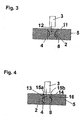
- a tolerance ring 13 being the first embodiment of the present invention allows a tolerance ring with outward waves 2 to be used in the apparatus but minimises or eliminates the particle production that results from the arrangements shown in Figures 1, 2 and 3 .
- the tolerance ring 13 includes a guide portion indicated generally in Figure 4 by 14.
- the guide portion 14 resembles a funnel, which flares towards the entrance of the bore 4.
- the guide portion comprises flared guide surfaces, indicated in cross section by 15a and 15b in Figure 4 , extending axially from the band 16 of the ring 13 towards the entrance of the bore 4.
- the guide surfaces 15a and 15b provide an enlarged entrance to the band 16 of the ring 13 for receiving the bearing, eliminating foul on the edge of the ring as described in Example 2.
- Guide surfaces 15a and 15b are sufficiently smooth so as to guide the bearing 3 into the ring 13, even if there is some axial misalignment of the bearing 3 and the ring 13. As the waves 2 of the ring 13 do not abrade against any surface during assembly and the end of the bearing 3 does not abrade against the ring 13, particle production is avoided.
- the arrangement using an S.V. type ring is preferable for the hard disk drive.
- the ring may be fitted to the end of a shaft and inserted into a bore in the housing, as shown in Figure 5 .
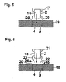
- the tolerance ring 17, with inwardly facing protrusions 2 is fitted to a shaft 18 and the shaft 18 and ring 17 inserted axially into the bore 4 of a housing 19.
- the diameter of the ring 17 is similar to the diameter of the bore 4 and so the ring 17 fouls on the edge 20 of the bore 4, producing particles from the ring 17 and / or the housing 19.
- This known tolerance ring can be modified by the provision of an inclined guide portion, in a manner similar to the first embodiment, but with the angle of inclination being inward rather than outward.
- Such an embodiment is illustrated in Figure 6 , and again reference numerals are used to indicate corresponding parts.
- Tolerance ring 21 of the second embodiment is fitted to a shaft 18, and axially inserted into the bore 4 of a housing 19.
- the ring 21 includes inward protrusions in the form of waves to the grip shaft 18.
- the ring includes a tapered guide portion indicated generally in Figure 6 by 22, extending axially from the band 23 of the ring, away from the shaft 18.
- the guide portion comprises guide surfaces, indicated in cross section in Figure 6 by 24a and 24b, sloping towards the axis of the ring to narrow the opening of the band 23.
- the guide surfaces 24a and 24b axially lead into the bore 4 during assembly.
- the guide surfaces allow correction of axial misalignment of the bearing and the bore.
- the guide portion prevents the ring fouling on the edge of the bore 20, reducing or even eliminating particle production.
- the bore 4 has straight side walls. It is possible for the ends of the bore to be chamfered, although the presence of the guide portion makes such chamfering of little benefit.
- the tolerance ring of the invention may be used on a hard disk drive, although there are numerous other applications of the present invention, for example any apparatus that uses a tolerance ring.
- the hard disk drive has an actuator arm pivotable around a bearing or bearing assembly.
- the actuator arm has an electronic transducer at one end for reading and writing data stored on a media disk.
- the arm pivots around a stationary shaft, which is mounted perpendicular to the plane of rotation of the media disk and arm.
- the pivot mechanism comprises a centre shaft and one or a plurality of rolling element bearings surrounding the shaft.
- Each rolling element bearing includes an inner race attached to the shaft, an outer race located concentrically around the inner race, and a plurality of rolling elements located in the annular space between the inner and outer races.
- Such an assembly is commonly known as a bearing cartridge assembly.
- An outer cylinder or sleeve may surround the outer race or races of the bearing or bearings.
Landscapes
- Engineering & Computer Science (AREA)
- General Engineering & Computer Science (AREA)
- Mechanical Engineering (AREA)
- Mounting Of Bearings Or Others (AREA)
- Laying Of Electric Cables Or Lines Outside (AREA)
- Snaps, Bayonet Connections, Set Pins, And Snap Rings (AREA)
- Paper (AREA)
- Control Of Motors That Do Not Use Commutators (AREA)
- Support Of The Bearing (AREA)
- Pens And Brushes (AREA)
- Coupling Device And Connection With Printed Circuit (AREA)
Abstract
Description
- This invention relates to tolerance ring assemblies, wherein a tolerance ring provides an interference fit between parts of an assembly, where a first part has a cylindrical portion located in a cylindrical bore of a second part. The invention particularly relates to assemblies having a tolerance ring that provides an interference fit between a cylindrical component such as a shaft or a bearing and a housing for the shaft.
- Improved engineering techniques have resulted in the need for greater accuracy of machine parts, raising manufacturing costs. Very close tolerances are required where press fits, splines, pins or keyways are employed to transmit torque in applications such as pulleys, flywheels or driveshafts.
- Tolerance rings may be used to provide an interference fit between parts required to transmit torque. Tolerance rings provide a low cost means of providing an interference fit between parts that may not be machined to exact dimensions. Tolerance rings have a number of other potential advantages, such as compensating for different linear coefficients of expansion between the parts, allowing rapid apparatus assembly, and durability.
- A tolerance ring generally comprises a strip of resilient material, for example a metal such as spring steel, the ends of which are brought together to form a ring. A band of protrusions extend radially outwards from the ring, or radially inwards towards the centre of the ring. Usually, the protrusions are formations, possibly regular formations, such as corrugations, ridges or waves.
- When the ring is located in the annular space between, for example, a shaft and a bore in a housing in which the shaft is located, the protrusions are compressed. Each protrusion acts as a spring and exerts a radial force against the shaft and the surface of the bore, providing an interference fit between the shaft and the housing. Rotation of the housing or the shaft will produce similar rotation in the other of the shaft or the housing, as torque is transmitted by the tolerance ring. Typically, the band of protrusions is axially flanked by annular regions of the ring that have no formations (known in the art as "unformed regions" of the tolerance ring).
- Although tolerance rings usually comprise a strip of resilient material that is curved to allow the easy formation of a ring by overlapping the ends of the strip, a tolerance ring may also be manufactured as an annular band. The term "tolerance ring" as used hereafter includes both types of tolerance ring. The term "shaft" as used hereafter includes any assembly component with a cylindrical portion, such as a shaft or a bearing.
- Problems can occur during assembly of parts that use tolerance rings. As the tolerance ring requires a tight fit in the apparatus, there may be abrasion between the ring and various parts of the apparatus, which removes small fragments from the surface of the affected parts. These fragments are known in the art as particles. In particular, parts of the protrusions distal to the band of the ring may generate particles when sliding relative to part(s) of the apparatus. In certain apparatus, such as a computer hard disk drive where cleanliness is essential, production of particles is extremely undesirable, as the particles can adversely affect the function of the apparatus.
- If the material of the housing (e.g. aluminium) is softer than the material of the shaft (e.g. steel), it may be desirable to have the protrusions slide relative to the shaft during assembly to minimise particle production. Normally, for this type of arrangement, the tolerance ring's protrusions point inwards.
- For apparatus that includes a bearing, however, it may also be desirable that the bearing has the tolerance ring fitted thereto, and the protrusions engage the surface of the bearing in the housing i.e. the protrusions point outwards. The arrangement may be useful where the tolerance ring distributes torque from the housing to the bearing, as load is distributed evenly over a large contact area of the shaft provided by the tolerance ring. Where the surface area is not maximised, for example when the protrusions engage the bearing under load, there may be problems with an effect known as "torque ripple" where the torque in the bearing is not generated at a continuous level. It is preferable that load is distributed over as large an area as possible, for example over the base of the protrusions of the tolerance ring.
- It may be advantageous to provide in the bore a tolerance ring with outward protrusions and fit the shaft into the ring. In this arrangement, although there may be reduced particle production as the protrusions do not slide relative to an apparatus component, particles may still be produced, as the end of the shaft may rub against the rim of the tolerance ring during assembly owing to the tight fit between the tolerance ring and the shaft.
- Alternatively, it may be advantageous to fit a tolerance ring with inward protrusions to the shaft, and insert the shaft and tolerance ring into the bore. Although the inward protrusions do not rub against the surface of the bore, particles may be produced when the rim of the tolerance ring rubs against the edge of the bore in the housing, owing to the tight fit between the ring and the housing.
- The need to reduce or eliminate particle production can therefore impose restrictions on the type of tolerance ring used. The tolerance ring that minimises particle production may not be the best choice for operation of the apparatus.
-
JP-A-59-166711 -
US-A-4981390 discloses an arrangement in which a shaft is mounted in a housing using a tolerance ring. In some embodiments the shaft has a disk thereon with the tolerance ring mounted on the periphery of that dish and held in place by tabs on the tolerance ring. - Therefore, a first aspect of the present invention proposes a method according to
claim 1. - A second aspect of the present invention proposes a method according to
claim 2. - The angle of inclination of the at least one guide surface relative to the axis may be constant along the length of the guide surface, so that the guide surface defines the major part of a frusto-cone. Alternatively, the angle of inclination may change so that the guide surface is curved in an axial section.
- An advantage of the present invention is correct assembly of a ring in a bore despite some axial misalignment of the ring and the bore.
- The tolerance ring may be made of any suitable resilient material, preferably a metal, most preferably spring steel. The guide surfaces of the guide portion may be flared relative to the inside surface of the band of the tolerance ring.
- Conveniently, the guide surfaces of the guide portion are sufficiently free of obstruction so as to guide a shaft inserted axially into the guide portion into the band. If there is axial misalignment of the shaft and the axis of the tolerance ring, the guide surfaces of the guide portion serve to align axially the shaft with the band as the shaft is inserted into the band. The guide portion may include walls that are substantially parallel to the axis of the ring, for example near to the entrance.
- Preferably, the entrance of the guide portion is circular or oval shaped. The entrance may be concentric with the band. The entrance may be rectangular or square in shape.
- Preferably, the plane of the entrance is substantially perpendicular to the axis of the tolerance ring. Alternatively, the plane of the opening may be slanted relative to the axis of the ring, and a segment of the entrance is axially closer to the band than the rest of the entrance.
- Ideally, the guide surface of any guide portion of the present invention is sufficiently smooth to prevent the production of particles when the guide surface rubs or slides against a shaft and / or the entrance to a bore in a housing. A possible advantage of the present invention is therefore a reduction in the particles normally generated when the tolerance ring is inserted inside a bore and/or fitted onto other apparatus, such as a shaft.
- The present invention is particularly suited to uses where particle production is undesirable, for example the hard disk drive of a computer. Additionally, or alternatively, the present invention may be particularly useful where it is advantageous to distribute tolerance ring loading over as wide an area as possible on a component that has to be inserted into or over the tolerance ring.
- Preferably the invention is used to produce a hard disk drive and the shaft is a bearing or bearing assembly and the housing is an actuator arm. Preferably, the actuator arm pivots around the bearing or bearing assembly. Preferably the bearing or bearing assembly remains stationary.
- Alternatively, the apparatus produced may be a torque limiting apparatus such as EPAS or a steering column lock, where slip occurs between the ring and another surface, an electric generator, a centrifugal pump, an air blower, a fan, a crane, woodworking or spinning machinery, a machine tool, a shaker or crusher.
- The guide surfaces of the guide portion may correct any axial misalignment between the shaft / ring and the bore to implement an interference fit between the ring and the shaft.
- The guide surface(s) of the guide portion may correct any axial misalignment between the shaft and the tolerance ring / bore.
- There may be a chamfer or flare at the mouth of the bore relative to the sides of the main section of the bore. This chamfer may act as a further guide, particularly in embodiments which the tolerance ring is mounted on a shaft prior to insertion in the bore. Such chamfers are, in themselves, already known.
- Embodiments of the present invention will now be described in detail, by way of example, reference to the accompanying drawings, in which:
-
Figure 1 shows in cross section a bearing and a known tolerance ring, which are about to be inserted into a bore in a pivotable actuator arm of a hard disk drive; -
Figure 2 shows in cross section another known tolerance ring with outward protrusions located in a bore in an actuator arm, and a bearing ready to be inserted into the tolerance ring; -
Figure 3 shows in cross section another known tolerance ring with inward protrusions located in a bore in an actuator arm, and a bearing ready to be inserted into the tolerance ring; -
Figure 4 shows in cross section a tolerance ring of the present invention located in a bore in an actuator arm, and a bearing ready to be inserted into the tolerance ring; -
Figure 5 shows in cross section, another known tolerance ring which is fitted to the end of a shaft and is about to be inserted into a bore in a housing; and -
Figure 6 shows in cross section a tolerance ring of the present invention, which is fitted to a shaft and is about to be inserted in a bore into a housing. - Before describing embodiments of the invention, it will be useful to understand conventional arrangements. Thus,
Figures 1 to 3 illustrate use of a known tolerance ring to mount a shaft in a bore. - Thus, as shown in
Figure 1 , a known tolerance ring with outwardly facing protrusions in the form ofwaves 2 and is fitted around abearing 3 or bearing assembly 3 (hereinafter referred to as the bearing 3). Thebearing 3 andtolerance ring 1 comprise a sub-assembly, which is axially inserted into thebore 4 of a body which may be anactuator arm 5 of a hard disk drive, indicated inFigure 1 by thearrow 6. Unformed, annular portions 7 of thetolerance ring 1, which have no radial protrusions, axially flank thewaves 2. Tolerance rings with outwardly facing protrusions are generally known in the art as S.V rings (Shaft Variable), as the diameter of the tolerance ring to be fitted to the bearing may be varied by differing amounts of overlap of the ends of the strip that forms the tolerance ring. Thewaves 2 of thering 1 resiliently engage thesurface 8 of thebore 4. - As the sub-assembly is inserted into the
bore 4, thewaves 2 of thetolerance ring 1 are compressed. Unformed portions 7 of thetolerance ring 1 that axially flank thewaves 2 prevent changes in the pitch of thewaves 2, allowing only resilient deformation of each wave. A radial force is created between thesurface 8 of thebore 4 and thebearing 3. An interference fit is thus provided by thetolerance ring 1. - During assembly, the
waves 2 of thetolerance ring 1 slide relative to thesurface 8 of thebore 4. Abrasion of the waves against thesurface 8 can cause small fragments of thehousing 5 to be removed from thesurface 8 of the bore 4 (and possibly tolerance ring 1). This problem is compounded if the material of theactuator arm 5 is softer than the material of thewaves 2 of thering 1. The fragments are known in the art as particles, which can adversely affect the operation of the apparatus in which thetolerance ring 1 is fitted. In the example, particles are extremely undesirable as cleanliness is important for proper functioning of the hard disk drive. - An alternative known assembly method comprises inserting the
tolerance ring 1 into thebore 4 so that thetolerance ring 1 sits concentrically in thebore 4. Thebearing 3 is inserted into thebore 4 and slides into thetolerance ring 1, as shown by thearrow 9 inFigure 2 . Thebearing 3 may foul on theedge 10 of the ring as thebearing 3 is axially inserted into thering 1, causing fragments of thering 1 and / orbearing 3 to be removed. The fragments are known in the art as particles. - Particles may also be produced when using a tolerance ring with inwardly extending protrusions, for example as shown
Figure 3 . Atolerance ring 11, with inwardly extendingwaves 2, sits concentrically in thebore 4 of theactuator arm 5, with the sides of the ring engaging thesides 8 of thebore 4. This type of ring is known in the art as an H.V. tolerance ring (Housing Variable). Abearing 3 is axially inserted into thering 11, as indicated inFigure 3 by thearrow 12. Thebearing 3 moves relative to thewaves 2. As thebearing 3 is made of harder material than theactuator arm 5, particle production is more limited. - The arrangement using a tolerance ring with inwardly extending waves may not be suitable for all types of apparatus, for example where it is desirable to have a load on the bearing spread over a wider area than can be provided by the tops of the waves. It is undesirable that a requirement to minimise particle production during assembly imposes a working arrangement that is sub-optimal for the apparatus.
- In a computer hard disk drive the arrangement using a tolerance ring with inwardly extending waves (H.V) is undesirable, as load must be spread over as wide an area of the bearing as possible to avoid torque ripple. Furthermore, axial alignment, required in a hard disk drive, is usually better with tolerance rings having outwardly extending waves (S.V), shown in
Figures 1 and 2 . However, manufacturers may use the H.V ring and assembly method described in Example 3, as it minimises particle production during assembly. Particles will adversely affect the functioning of the hard disk drive. - As had previously been mentioned, a tolerance ring according to the present invention modifies known tolerance rings by providing a guide portion which is inclined relative to the axis of the tolerance ring. The first embodiment of the present invention will now be described with reference to
Figure 4 . Some of the features of the tolerance ring of this embodiment are the same in the tolerance rings described previously, and the same reference numerals will be used to indicate corresponding parts. - A
tolerance ring 13 being the first embodiment of the present invention allows a tolerance ring withoutward waves 2 to be used in the apparatus but minimises or eliminates the particle production that results from the arrangements shown inFigures 1, 2 and3 . Thetolerance ring 13 includes a guide portion indicated generally inFigure 4 by 14. Theguide portion 14 resembles a funnel, which flares towards the entrance of thebore 4. The guide portion comprises flared guide surfaces, indicated in cross section by 15a and 15b inFigure 4 , extending axially from theband 16 of thering 13 towards the entrance of thebore 4. - The guide surfaces 15a and 15b provide an enlarged entrance to the
band 16 of thering 13 for receiving the bearing, eliminating foul on the edge of the ring as described in Example 2. Guide surfaces 15a and 15b are sufficiently smooth so as to guide thebearing 3 into thering 13, even if there is some axial misalignment of thebearing 3 and thering 13. As thewaves 2 of thering 13 do not abrade against any surface during assembly and the end of thebearing 3 does not abrade against thering 13, particle production is avoided. The arrangement using an S.V. type ring is preferable for the hard disk drive. - It is also known to use a tolerance ring with inwardly facing protrusions. The ring may be fitted to the end of a shaft and inserted into a bore in the housing, as shown in
Figure 5 . Thetolerance ring 17, with inwardly facingprotrusions 2, is fitted to ashaft 18 and theshaft 18 andring 17 inserted axially into thebore 4 of ahousing 19. The diameter of thering 17 is similar to the diameter of thebore 4 and so thering 17 fouls on theedge 20 of thebore 4, producing particles from thering 17 and / or thehousing 19. - This known tolerance ring can be modified by the provision of an inclined guide portion, in a manner similar to the first embodiment, but with the angle of inclination being inward rather than outward. Such an embodiment is illustrated in
Figure 6 , and again reference numerals are used to indicate corresponding parts.Tolerance ring 21 of the second embodiment is fitted to ashaft 18, and axially inserted into thebore 4 of ahousing 19. Thering 21 includes inward protrusions in the form of waves to thegrip shaft 18. - The ring includes a tapered guide portion indicated generally in
Figure 6 by 22, extending axially from theband 23 of the ring, away from theshaft 18. The guide portion comprises guide surfaces, indicated in cross section inFigure 6 by 24a and 24b, sloping towards the axis of the ring to narrow the opening of theband 23. The guide surfaces 24a and 24b axially lead into thebore 4 during assembly. The guide surfaces allow correction of axial misalignment of the bearing and the bore. The guide portion prevents the ring fouling on the edge of thebore 20, reducing or even eliminating particle production. - In the embodiments described above, the
bore 4 has straight side walls. It is possible for the ends of the bore to be chamfered, although the presence of the guide portion makes such chamfering of little benefit. - The tolerance ring of the invention may be used on a hard disk drive, although there are numerous other applications of the present invention, for example any apparatus that uses a tolerance ring. In the example, the hard disk drive has an actuator arm pivotable around a bearing or bearing assembly. Typically, the actuator arm has an electronic transducer at one end for reading and writing data stored on a media disk. The arm pivots around a stationary shaft, which is mounted perpendicular to the plane of rotation of the media disk and arm.
- Conventionally, the pivot mechanism comprises a centre shaft and one or a plurality of rolling element bearings surrounding the shaft. Each rolling element bearing includes an inner race attached to the shaft, an outer race located concentrically around the inner race, and a plurality of rolling elements located in the annular space between the inner and outer races. Such an assembly is commonly known as a bearing cartridge assembly. An outer cylinder or sleeve may surround the outer race or races of the bearing or bearings. Although such a hard disk drive is a typical arrangement, it will be appreciated by those in the art that there are other possible arrangements to which the invention can be applied.
Claims (3)
- A method of assembling an apparatus comprising:inserting a tolerance ring (13) in a bore in a housing, the tolerance ring comprising:a band (16) of resilient material having corrugated protrusions (2) extending radially outwards from the band, and a guide portion (14) contiguous with, and extending axially from the whole circumference of the band (16), wherein the band has annular portions, which have no radial protrusions, axially flanking the protrusions, and the guide portion (14) comprises at least one guide surface (15a, 15b) inclined at an constant angle relative to the axis of the band along the length of the guide surface such that the free end of the guide portion is wider than the opening of the band, the protrusions of the tolerance ring engaging the wall of the bore when the tolerance ring is inserted into the bore;inserting an end of a shaft into the guide portion of the tolerance ring; andmoving the shaft along the axis of the band into the band, so that the band engages the shaft, whereby the protrusions are compressed to exert a radial spring force between the shaft and the wall of the bore.
- A method of assembling an apparatus, comprising:mounting a tolerance ring (22) on a shaft, the tolerance ring comprising a band (23) of resilient material having corrugated protrusions (2) extending radially inwards towards the axis of the band, and a guide portion (24a, 24b) contiguous with, and extending axially from the whole circumference of the band, wherein the band has annular portions, which have no radial protrusions, axially flanking the protrusions, and the guide portion (24a, 24b) comprises at least one guide surface inclined relative to the axis of the band such that the free end of the guide portion is narrower than the opening of the band, the protrusions of the tolerance ring engaging the shaft;inserting the guide portion of the tolerance ring into a bore in a housing; andmoving the shaft and tolerance ring axially into the bore such that the band engages the wall of the bore, whereby the protrusions are compressed to exert a radial spring force between the shaft and the wall of the bore.
- A method according to claim 2 wherein the angle of inclination of the at least one guide surface relative to said axis is constant along the length of the guide surface.
Priority Applications (1)
| Application Number | Priority Date | Filing Date | Title |
|---|---|---|---|
| EP09013623.5A EP2154388B1 (en) | 2003-04-17 | 2004-04-16 | Tolerance ring assembly |
Applications Claiming Priority (2)
| Application Number | Priority Date | Filing Date | Title |
|---|---|---|---|
| GBGB0308957.0A GB0308957D0 (en) | 2003-04-17 | 2003-04-17 | Tolerance ring assembly |
| PCT/GB2004/001681 WO2004094852A1 (en) | 2003-04-17 | 2004-04-16 | Tolerance ring assembly |
Related Child Applications (2)
| Application Number | Title | Priority Date | Filing Date |
|---|---|---|---|
| EP09013623.5A Division EP2154388B1 (en) | 2003-04-17 | 2004-04-16 | Tolerance ring assembly |
| EP09013623.5A Division-Into EP2154388B1 (en) | 2003-04-17 | 2004-04-16 | Tolerance ring assembly |
Publications (3)
| Publication Number | Publication Date |
|---|---|
| EP1613869A1 EP1613869A1 (en) | 2006-01-11 |
| EP1613869B1 EP1613869B1 (en) | 2010-01-06 |
| EP1613869B2 true EP1613869B2 (en) | 2014-09-03 |
Family
ID=9956991
Family Applications (2)
| Application Number | Title | Priority Date | Filing Date |
|---|---|---|---|
| EP04727948.4A Expired - Lifetime EP1613869B2 (en) | 2003-04-17 | 2004-04-16 | Tolerance ring assembly |
| EP09013623.5A Expired - Lifetime EP2154388B1 (en) | 2003-04-17 | 2004-04-16 | Tolerance ring assembly |
Family Applications After (1)
| Application Number | Title | Priority Date | Filing Date |
|---|---|---|---|
| EP09013623.5A Expired - Lifetime EP2154388B1 (en) | 2003-04-17 | 2004-04-16 | Tolerance ring assembly |
Country Status (9)
| Country | Link |
|---|---|
| US (7) | US9206853B2 (en) |
| EP (2) | EP1613869B2 (en) |
| CN (1) | CN100340784C (en) |
| AT (1) | ATE454563T1 (en) |
| DE (1) | DE602004024971D1 (en) |
| ES (1) | ES2339020T5 (en) |
| GB (1) | GB0308957D0 (en) |
| PL (1) | PL2154388T3 (en) |
| WO (1) | WO2004094852A1 (en) |
Families Citing this family (65)
| Publication number | Priority date | Publication date | Assignee | Title |
|---|---|---|---|---|
| GB0308957D0 (en) | 2003-04-17 | 2003-05-28 | Lillishall Plastics And Engine | Tolerance ring assembly |
| US20060046858A1 (en) * | 2004-08-26 | 2006-03-02 | Ronald Brissette | Driveshaft assembly with torque ring coupling |
| GB0615672D0 (en) * | 2006-08-07 | 2006-09-13 | Rencol Tolerance Rings Ltd | Assembly of a shaft and a housing assembly |
| US7850389B2 (en) * | 2006-08-15 | 2010-12-14 | Intriplex Technologies, Inc. | Tolerance ring having various end tab designs to prevent interlocking |
| US7583476B2 (en) * | 2006-08-22 | 2009-09-01 | Intri-Plex Technologies, Inc. | Tolerance ring for data storage with cut-out feature for mass control |
| SE530706C2 (en) * | 2006-12-27 | 2008-08-19 | Hudiksvalls Teknik Ct Ab | Coupling |
| US8233242B2 (en) | 2007-04-24 | 2012-07-31 | Saint-Gobain Performance Plastics Rencol Limited | Tolerance ring with overlapping layers |
| EP1985875B1 (en) * | 2007-04-24 | 2013-10-02 | Saint-Gobain Performance Plastics Rencol Limited | Mounting assembly |
| KR101062201B1 (en) * | 2007-05-22 | 2011-09-05 | 삼성전자주식회사 | Flat panel display and flat panel display device having the same |
| EP2218070B1 (en) * | 2007-11-15 | 2012-06-06 | Intri-Plex Technologies, Inc. | Tolerance ring for data storage with overlapping tab feature for mass control |
| DE102007056340A1 (en) * | 2007-11-22 | 2009-05-28 | Wabco Gmbh | Clamping bush for a sensor |
| ES2447591T3 (en) * | 2008-05-14 | 2014-03-12 | Saint-Gobain Performance Plastics Rencol Ltd. | Mounting method and device |
| EP2337962B1 (en) * | 2008-09-10 | 2014-04-16 | Saint-Gobain Performance Plastics Rencol Ltd. | Tolerance ring and mounting assembly with such a tolerance ring |
| GB2465435B (en) * | 2008-11-25 | 2011-02-23 | Saint Gobain Performance Plast | Process control of tolerance rings |
| US8944690B2 (en) * | 2009-08-28 | 2015-02-03 | Saint-Gobain Performance Plastics Pampus Gmbh | Corrosion resistant bushing |
| US20110076096A1 (en) | 2009-09-25 | 2011-03-31 | Saint-Gobain Performance Plastics Rencol Limited | System, method and apparatus for tolerance ring control of slip interface sliding forces |
| US9812684B2 (en) | 2010-11-09 | 2017-11-07 | GM Global Technology Operations LLC | Using elastic averaging for alignment of battery stack, fuel cell stack, or other vehicle assembly |
| US9399556B2 (en) * | 2011-08-11 | 2016-07-26 | Mol Belting Systems, Inc. | End lid design and removal tool |
| US9618026B2 (en) | 2012-08-06 | 2017-04-11 | GM Global Technology Operations LLC | Semi-circular alignment features of an elastic averaging alignment system |
| US9463538B2 (en) | 2012-08-13 | 2016-10-11 | GM Global Technology Operations LLC | Alignment system and method thereof |
| US20140041185A1 (en) * | 2012-08-13 | 2014-02-13 | GM Global Technology Operations LLC | Elastic tube alignment and attachment system and method for precisely locating and attaching components |
| US9556890B2 (en) | 2013-01-31 | 2017-01-31 | GM Global Technology Operations LLC | Elastic alignment assembly for aligning mated components and method of reducing positional variation |
| US9382935B2 (en) | 2013-04-04 | 2016-07-05 | GM Global Technology Operations LLC | Elastic tubular attachment assembly for mating components and method of mating components |
| US9388838B2 (en) | 2013-04-04 | 2016-07-12 | GM Global Technology Operations LLC | Elastic retaining assembly for matable components and method of assembling |
| US9278642B2 (en) | 2013-04-04 | 2016-03-08 | GM Global Technology Operations LLC | Elastically deformable flange locator arrangement and method of reducing positional variation |
| US9297400B2 (en) | 2013-04-08 | 2016-03-29 | GM Global Technology Operations LLC | Elastic mating assembly and method of elastically assembling matable components |
| US9447840B2 (en) | 2013-06-11 | 2016-09-20 | GM Global Technology Operations LLC | Elastically deformable energy management assembly and method of managing energy absorption |
| US9243655B2 (en) | 2013-06-13 | 2016-01-26 | GM Global Technology Operations LLC | Elastic attachment assembly and method of reducing positional variation and increasing stiffness |
| US9488205B2 (en) | 2013-07-12 | 2016-11-08 | GM Global Technology Operations LLC | Alignment arrangement for mated components and method |
| US9303667B2 (en) | 2013-07-18 | 2016-04-05 | Gm Global Technology Operations, Llc | Lobular elastic tube alignment system for providing precise four-way alignment of components |
| US9863454B2 (en) | 2013-08-07 | 2018-01-09 | GM Global Technology Operations LLC | Alignment system for providing precise alignment and retention of components of a sealable compartment |
| US9458876B2 (en) | 2013-08-28 | 2016-10-04 | GM Global Technology Operations LLC | Elastically deformable alignment fastener and system |
| US9463831B2 (en) | 2013-09-09 | 2016-10-11 | GM Global Technology Operations LLC | Elastic tube alignment and fastening system for providing precise alignment and fastening of components |
| US9457845B2 (en) | 2013-10-02 | 2016-10-04 | GM Global Technology Operations LLC | Lobular elastic tube alignment and retention system for providing precise alignment of components |
| US9511802B2 (en) | 2013-10-03 | 2016-12-06 | GM Global Technology Operations LLC | Elastically averaged alignment systems and methods |
| US9669774B2 (en) | 2013-10-11 | 2017-06-06 | GM Global Technology Operations LLC | Reconfigurable vehicle interior assembly |
| US9481317B2 (en) | 2013-11-15 | 2016-11-01 | GM Global Technology Operations LLC | Elastically deformable clip and method |
| US9447806B2 (en) | 2013-12-12 | 2016-09-20 | GM Global Technology Operations LLC | Self-retaining alignment system for providing precise alignment and retention of components |
| US9428123B2 (en) | 2013-12-12 | 2016-08-30 | GM Global Technology Operations LLC | Alignment and retention system for a flexible assembly |
| US9216704B2 (en) | 2013-12-17 | 2015-12-22 | GM Global Technology Operations LLC | Elastically averaged strap systems and methods |
| US9599279B2 (en) | 2013-12-19 | 2017-03-21 | GM Global Technology Operations LLC | Elastically deformable module installation assembly |
| US9446722B2 (en) | 2013-12-19 | 2016-09-20 | GM Global Technology Operations LLC | Elastic averaging alignment member |
| US9238488B2 (en) | 2013-12-20 | 2016-01-19 | GM Global Technology Operations LLC | Elastically averaged alignment systems and methods |
| US9541113B2 (en) | 2014-01-09 | 2017-01-10 | GM Global Technology Operations LLC | Elastically averaged alignment systems and methods |
| US9463829B2 (en) | 2014-02-20 | 2016-10-11 | GM Global Technology Operations LLC | Elastically averaged alignment systems and methods |
| US9428046B2 (en) | 2014-04-02 | 2016-08-30 | GM Global Technology Operations LLC | Alignment and retention system for laterally slideably engageable mating components |
| CN103912415A (en) * | 2014-04-22 | 2014-07-09 | 无锡隆盛科技股份有限公司 | Center pole end cover structure of electric EGR (exhaust gas recirculation) valve of gasoline engine |
| US9657807B2 (en) | 2014-04-23 | 2017-05-23 | GM Global Technology Operations LLC | System for elastically averaging assembly of components |
| US9429176B2 (en) | 2014-06-30 | 2016-08-30 | GM Global Technology Operations LLC | Elastically averaged alignment systems and methods |
| WO2016005817A2 (en) | 2014-07-11 | 2016-01-14 | Saint-Gobain Performance Plastics Rencol Limited | Stepped assembly |
| US9293162B1 (en) * | 2014-09-09 | 2016-03-22 | HGST Netherlands B.V. | Actuator comb having a stepped inner bore |
| CN204419897U (en) * | 2014-09-23 | 2015-06-24 | 美国圣戈班性能塑料公司 | The reeded assembly of tool |
| US9758110B2 (en) | 2015-01-12 | 2017-09-12 | GM Global Technology Operations LLC | Coupling system |
| CN107250542B (en) * | 2015-01-27 | 2020-04-03 | 株式会社电装 | Fuel pump |
| US9908167B1 (en) | 2015-03-02 | 2018-03-06 | Western Digital Technologies, Inc. | Disk drive tolerance ring with edge rounding from opposite major faces |
| US10107319B2 (en) | 2015-03-02 | 2018-10-23 | GM Global Technology Operations LLC | Elastically averaged alignment systems and methods |
| DE102016214505A1 (en) | 2016-08-05 | 2018-02-08 | Robert Bosch Gmbh | Compensation sleeve for a bearing device, bearing device with a compensating sleeve and method for mounting a compensating sleeve |
| CN107791242A (en) * | 2017-11-23 | 2018-03-13 | 深圳市优必选科技有限公司 | Steering wheel and robot |
| JP2021507659A (en) | 2017-12-15 | 2021-02-22 | サン−ゴバン パフォーマンス プラスティックス レンコール リミティド | Cyclic members, methods, and assemblies for component displacement control |
| CA3160529A1 (en) | 2019-11-07 | 2021-05-14 | Saint-Gobain Performance Plastics Rencol Limited | Electrically conductive bearings |
| WO2021113599A1 (en) | 2019-12-06 | 2021-06-10 | Saint-Gobain Performance Plastics Corporation | Flanged bearing, assembly, and method of making and using the same |
| EP4073397B1 (en) | 2019-12-13 | 2026-03-25 | Saint-Gobain Performance Plastics Rencol Limited | Assembly comprising a tolerance ring between two components with desired slipping torque at the surfaces of contact |
| JP2024520214A (en) | 2021-07-02 | 2024-05-22 | サン-ゴバン パフォーマンス プラスチックス パンプス ゲゼルシャフト ミット ベシュレンクテル ハフツング | Flanged bearings, assemblies, and methods of making and using same |
| KR20240124302A (en) | 2021-12-21 | 2024-08-16 | 생-고뱅 퍼포먼스 플라스틱스 코포레이션 | Electrically conductive bearing having ribs, and method for manufacturing and using the same |
| CN116292318A (en) * | 2023-04-12 | 2023-06-23 | 浙江尔格科技股份有限公司 | Transformer oil-immersed oil pump and its bearing assembly structure and bearing assembly method |
Citations (6)
| Publication number | Priority date | Publication date | Assignee | Title |
|---|---|---|---|---|
| GB414631A (en) † | 1932-10-31 | 1934-08-09 | Hermann Facklam | Bolt retainer |
| DD50166A1 (en) † | 1965-11-09 | 1966-10-25 | RADIAL SPANNING ELEMENT FOR THE CONVENTIONAL CONNECTION OF A CYLINDRICAL SHAPED BODY INSERTABLE INTO A CYLINDRICAL HOLE OR HUB | |
| US3838928A (en) † | 1972-03-06 | 1974-10-01 | Star Kugelhalter Gmbh Dt | Spacer ring |
| US4828423A (en) † | 1987-04-06 | 1989-05-09 | Cramer Jr Arthur A | Tolerance ring and shim |
| US4981390A (en) † | 1987-03-06 | 1991-01-01 | The Ray Engineering Co., Ltd. | Tolerance ring with retaining means |
| WO2001059314A1 (en) † | 2000-02-09 | 2001-08-16 | Seagate Technology Llc | Tolerance ring with high hoop strength to resist deformation |
Family Cites Families (187)
| Publication number | Priority date | Publication date | Assignee | Title |
|---|---|---|---|---|
| DE50166C (en) | E. PLESS in Berlin, Kochstrafse 48 | Automatic vending machine | ||
| US1469880A (en) * | 1920-10-08 | 1923-10-09 | Schraders Son Inc | Dust-cap spring |
| GB195795A (en) | 1922-01-19 | 1923-04-12 | Sidney Harold Oldfield | Improvements relating to tripod and like stands |
| US1931073A (en) * | 1931-11-07 | 1933-10-17 | Bantam Ball Bearing Company | Antifriction bearing |
| US2386951A (en) * | 1942-04-23 | 1945-10-16 | Gen Motors Corp | Method of making bearings |
| US2886354A (en) * | 1950-02-02 | 1959-05-12 | Bjorklund Gustaf Erik | Fasteners |
| GB687691A (en) | 1950-02-02 | 1953-02-18 | Gustaf Erik Bjorklund | Improvement in friction connections |
| DK76160C (en) * | 1950-05-10 | 1953-07-27 | Star Kugelhalter Gmbh Dt | Spring strap and a curved ring of corrugated steel sheet thereof. |
| US2931412A (en) * | 1954-10-14 | 1960-04-05 | Luman B Wing | Corrugated spring steel bushing |
| FR1116088A (en) * | 1954-11-09 | 1956-05-03 | Hohenzollern Huettenverwalt | Composite pad |
| GB866678A (en) * | 1958-01-01 | 1961-04-26 | Star Kugelhalter Gmbh Dt | Improvements in or relating to seatings for machine parts |
| US2992868A (en) * | 1958-05-07 | 1961-07-18 | Vacha Fred | Mounting sleeve |
| US3094376A (en) * | 1958-10-03 | 1963-06-18 | American Metal Prod | Method of construction of low friction elements |
| US3104136A (en) * | 1960-05-19 | 1963-09-17 | Henry H Merriman | Bushing |
| US3142887A (en) * | 1960-09-14 | 1964-08-04 | Star Kugelhalter Gmbh Dt | Method of making a split annular tolerance ring |
| US3061386A (en) * | 1961-10-04 | 1962-10-30 | Star Kugelhalter Gmbh Dt | Tolerance rings |
| US3151330A (en) * | 1962-02-13 | 1964-10-06 | Gen Am Transport | Tools for driving thin-walled metal ferrules |
| DE1872950U (en) | 1963-02-25 | 1963-05-30 | Star Kugelhalter Gmbh Dt | TOLERANCE RING. |
| GB972589A (en) | 1963-04-16 | 1964-10-14 | John Wilfred Sandberg | Locking mechanism for telescoping members |
| US3438660A (en) * | 1964-10-23 | 1969-04-15 | Lajos Steiner | Mechanical clamping means |
| GB1205749A (en) * | 1966-11-29 | 1970-09-16 | Silentbloc | Pivotal joint |
| JPS4821050B1 (en) | 1967-10-14 | 1973-06-26 | ||
| US3586402A (en) * | 1967-11-09 | 1971-06-22 | Textron Inc | Self-locking bearing ring |
| US3626743A (en) * | 1969-12-22 | 1971-12-14 | Roller Bearing Co | Making corrugated elastic shims |
| US3633398A (en) * | 1970-01-21 | 1972-01-11 | Roller Bearing Co Of America | Making corrugated elastic shims |
| DE2018367B1 (en) * | 1970-04-16 | 1971-07-29 | Deutsche Star Kugelhalter Gmbh, 8720 Schweinfurt | Connection element for a coupling with clamping sleeve for fastening a hub on a shaft |
| US3747997A (en) * | 1971-07-22 | 1973-07-24 | Mechanical Tech Inc | Hydrodynamic foil bearings |
| SE414137B (en) * | 1972-01-12 | 1980-07-14 | Stihl Maschf Andreas | CLUTCH DEVICE FOR ADDITIVES, SEPARATE ADDITIVES FOR ENGINE CHAIN SAW |
| FR2271443B2 (en) * | 1974-01-23 | 1977-06-10 | Pitner Alfred | |
| DE2527681C3 (en) * | 1975-06-21 | 1978-05-24 | Multi-Contact Ag, Allschwil (Schweiz) | Electrical contact arrangement |
| AT335234B (en) * | 1975-09-24 | 1977-02-25 | Miba Gleitlager Ag | SLIDING BEARING AND METHOD OF ITS MANUFACTURING |
| US4079168A (en) * | 1976-11-01 | 1978-03-14 | Lord Corporation | Rubber-metal composite structures having improved resistance to corrosion |
| US4286894A (en) * | 1979-03-21 | 1981-09-01 | Roller Bearing Company Of America | Tolerance rings |
| DE2934271C2 (en) | 1979-08-24 | 1983-11-10 | MTU Motoren- und Turbinen-Union München GmbH, 8000 München | Aerodynamic radial bearing for high-speed flow machines |
| JPS5649415A (en) | 1979-09-28 | 1981-05-06 | Taiho Kogyo Co Ltd | Sliding bearing |
| US4269550A (en) * | 1980-03-14 | 1981-05-26 | Digiulio Mario | Drill bushing for use in a metal tooling plate |
| US4376254A (en) | 1981-06-10 | 1983-03-08 | General Motors Corporation | Annular molded article secured to a shaft |
| DE3248148C2 (en) * | 1982-12-27 | 1985-01-31 | Daimler-Benz Ag, 7000 Stuttgart | Clamping sleeve |
| JPS59166711A (en) * | 1983-03-11 | 1984-09-20 | Taiho Kogyo Co Ltd | Bush |
| JPS59166711U (en) | 1983-04-26 | 1984-11-08 | 日本ノ−シヨン工業株式会社 | Buttons for clothing, etc. |
| DD218655A1 (en) | 1983-05-02 | 1985-02-13 | Elektrogeraete Ingbuero Veb | ELASTIC ELEMENT FOR TOLERANCE-EFFICIENT INSTALLATION OF BEARINGS |
| DE3405083A1 (en) * | 1983-10-10 | 1985-08-14 | Ed. Scharwächter GmbH & Co KG, 5630 Remscheid | REMOVABLE WING HINGE |
| CH671239A5 (en) * | 1986-07-15 | 1989-08-15 | Balzers Hochvakuum | |
| JPS6376908A (en) | 1986-09-18 | 1988-04-07 | Yobea Rulon Kogyo Kk | Rolling bearing |
| ATE80671T1 (en) * | 1986-12-23 | 1992-10-15 | Balzers Hochvakuum | COMPOSITE MATERIAL WITH A SLIDING LAYER APPLIED BY CATHODE SPRAYING. |
| US4790683A (en) * | 1987-10-05 | 1988-12-13 | Cramer Jr Arthur A | Tolerance ring and shim and method of use |
| JPH02101947A (en) * | 1988-10-07 | 1990-04-13 | Asmo Co Ltd | Commutator and manufacture thereof |
| US4932795A (en) * | 1988-11-10 | 1990-06-12 | Outboard Marine Corporation | Electrically conductive plastic bushings for marine propulsion devices |
| SU1646706A2 (en) * | 1989-06-06 | 1991-05-07 | Предприятие П/Я А-3680 | Workpiece clamping device |
| JPH0348013A (en) | 1989-07-13 | 1991-03-01 | Showa Aircraft Ind Co Ltd | bearing device |
| US5030260A (en) | 1989-12-04 | 1991-07-09 | International Business Machines Corporation | Disk drive breather filter |
| JPH0737679B2 (en) * | 1989-12-05 | 1995-04-26 | 大同メタル工業株式会社 | Plain bearing |
| EP0503213A1 (en) | 1991-03-08 | 1992-09-16 | The Pullman Company | Improved rubber-metal bushing and method of producing same |
| JP2959165B2 (en) | 1991-03-13 | 1999-10-06 | オイレス工業株式会社 | Oil-free bearing and manufacturing method thereof |
| GB2254399B (en) | 1991-04-03 | 1995-02-01 | Stanton Plc | Seal bushes for rotary shafts |
| DE4114643C2 (en) * | 1991-05-04 | 1995-12-21 | Schaeffler Waelzlager Kg | Rolling bearings, in particular for steering columns |
| EP0514329B1 (en) | 1991-05-16 | 1995-09-20 | The Pullman Company | Improved rubber-metal bushing and method of producing same |
| US5315465A (en) | 1991-07-12 | 1994-05-24 | Seagate Technology, Inc. | Compliant pivot mechanism for a rotary actuator |
| JP3009516B2 (en) | 1991-08-21 | 2000-02-14 | エヌティエヌ株式会社 | Anti-corrosion rolling bearing |
| JP2967245B2 (en) | 1991-08-22 | 1999-10-25 | 株式会社日立製作所 | Waterless pump |
| US5413374A (en) * | 1991-08-30 | 1995-05-09 | Nai Neway, Inc. | Adjustable bushing |
| JPH0598463A (en) | 1991-10-04 | 1993-04-20 | Hitachi Metals Ltd | Composite surface treating method and cast iron member subjected to composite surface treatment |
| JP3110537B2 (en) | 1991-12-27 | 2000-11-20 | 倉敷化工株式会社 | Sliding body |
| FR2686951B1 (en) * | 1992-01-31 | 1996-06-07 | Nadella | RADIAL BEARING WITHOUT IMPROVED GAME AND ITS APPLICATION TO AN AUTOMOBILE STEERING COLUMN. |
| DE4213831C2 (en) * | 1992-04-28 | 1996-06-20 | Glyco Metall Werke | Rolled bearing bush and pin or shaft connection with such a bearing bush |
| US5305654A (en) * | 1993-06-07 | 1994-04-26 | Durham Roger O | Headset for bicycles with external forks |
| GB9312445D0 (en) | 1993-06-16 | 1993-07-28 | Lillishaw Plastics And Enginee | Tolerance rings |
| JPH0790533A (en) | 1993-09-14 | 1995-04-04 | Hitachi Ltd | Sleeve, manufacturing method thereof, and drainage pump including the sleeve |
| NZ279471A (en) | 1994-02-08 | 1998-02-26 | Plastic Bearings & Housings Au | Bearing; structural details of a plain bearing |
| EP0749449A1 (en) * | 1994-03-11 | 1996-12-27 | Raychem Corporation | Curable polymeric composition and use in protecting a substrate |
| DE4442186C2 (en) * | 1994-11-26 | 1999-03-04 | Glyco Metall Werke | Layer material and process for its production |
| CN1126286A (en) | 1995-01-05 | 1996-07-10 | 孟凡昌 | Composite bearing and its prepn. technique |
| JP3411726B2 (en) | 1995-05-01 | 2003-06-03 | 光洋精工株式会社 | Electric power steering device |
| US5633086A (en) * | 1995-05-31 | 1997-05-27 | The United States Of America As Represented By The Secretary Of Commerce | Friction and wear resistant coating for titanium and its alloys |
| JPH0960397A (en) | 1995-08-17 | 1997-03-04 | Norton Kk | Bearing for hinge |
| US5803614A (en) * | 1996-07-15 | 1998-09-08 | Daido Metal Company, Ltd. | Bearing structure of sliding bearing |
| US6228471B1 (en) * | 1997-02-04 | 2001-05-08 | N.V. Bekaert S.A. | Coating comprising layers of diamond like carbon and diamond like nanocomposite compositions |
| US6130404A (en) | 1997-03-03 | 2000-10-10 | Itt Automotive, Inc. | Electro-optical removal of plastic layer bonded to a metal tube |
| US5906029A (en) * | 1997-03-25 | 1999-05-25 | Fox; Larry | Hinge repair kit and installation method |
| US5902049A (en) | 1997-03-28 | 1999-05-11 | Mohawk Innovative Technology, Inc. | High load capacity compliant foil hydrodynamic journal bearing |
| JP3168538B2 (en) * | 1997-04-19 | 2001-05-21 | チャン リー ウー | Sliding bearing and method of manufacturing the same |
| US5999373A (en) | 1997-09-29 | 1999-12-07 | Seagate Technology, Inc. | Bearing cartridge for a disc drive |
| US5964474A (en) * | 1997-12-30 | 1999-10-12 | Chen; Chia-Chin | Headset assembly for a bicycle |
| JP3859344B2 (en) * | 1998-01-28 | 2006-12-20 | 株式会社小松製作所 | Sliding material, sliding member and method of manufacturing the sliding member |
| US6163441A (en) | 1998-02-24 | 2000-12-19 | Seagate Technology Llc | Resonance dampening actuator bearing assembly |
| CA2321641A1 (en) | 1998-02-27 | 1999-09-02 | Allison Engine Company, Inc. | Method and apparatus for mounting a bearing |
| DE19915417C2 (en) * | 1998-04-04 | 2001-07-19 | Gkn Automotive Gmbh | Tripod joint with elastic means |
| US6000853A (en) * | 1998-05-01 | 1999-12-14 | Federal-Mogul World Wide, Inc. | Multi-layer engine bearings and method of manufacture |
| US6603634B1 (en) * | 1998-06-05 | 2003-08-05 | Seagate Technology Llc | Compressive spring sleeve for reducing disc slippage |
| US6018441A (en) * | 1998-06-08 | 2000-01-25 | Read-Rite Corporation | Disk drive pivot bearing and actuator arm assembly |
| EP1123246A4 (en) * | 1998-07-31 | 2003-04-09 | Shuttleworth Inc | Low electrostatic discharge conveyor |
| US6114040A (en) * | 1998-09-09 | 2000-09-05 | E. I. Du Pont De Nemours And Company | Cathodic electrodeposited coatings having high lubricity |
| GB2342425B (en) | 1998-10-03 | 2002-12-04 | Jaguar Cars | Centering bush |
| JP2000120663A (en) | 1998-10-20 | 2000-04-25 | Ebara Corp | Bearing |
| JP2000188856A (en) | 1998-12-22 | 2000-07-04 | Matsushita Electric Ind Co Ltd | Spindle motor |
| AUPP924699A0 (en) * | 1999-03-17 | 1999-04-15 | 21St Century Coatings (Aust) Pty. Ltd. | Fluorinated polymer and coating composition |
| US6411472B1 (en) * | 1999-04-21 | 2002-06-25 | Seagate Technology Llc | Dual metal laminate tolerance ring for acoustic and vibration damping |
| US6813120B1 (en) | 1999-05-12 | 2004-11-02 | Seagate Technology Llc | Encased E-block |
| JP2001027251A (en) * | 1999-07-14 | 2001-01-30 | Minebea Co Ltd | Bearing and manufacture thereof |
| US7367107B1 (en) * | 1999-07-15 | 2008-05-06 | Maxtor Corporation | Method for making a disk drive head stack assembly having a tapered pivot bearing |
| JP2001208082A (en) | 1999-11-16 | 2001-08-03 | Minebea Co Ltd | Pivot bearing |
| DE10085247T1 (en) | 1999-12-03 | 2002-11-07 | Seagate Technology Llc | Tolerance ring with a consistent low installation force profile |
| US6186027B1 (en) * | 2000-02-23 | 2001-02-13 | Peter M. Nielsen | Handlebar stem assembly for bicycle fork |
| JP2001240933A (en) * | 2000-02-29 | 2001-09-04 | Daido Metal Co Ltd | Copper-based sliding material, its manufacturing method and sliding bearing material, its manufacturing method |
| US6321712B1 (en) * | 2000-04-07 | 2001-11-27 | Dana Corporation | Racing engine having trimetal bearings with a thick overlay for high speed and/or high load applications |
| US6480363B1 (en) * | 2000-05-22 | 2002-11-12 | International Business Machines Corporation | Hard disk drive actuator assembly with damped tolerance ring for enhancing drive performance during structural resonance modes |
| DE10027513A1 (en) | 2000-06-06 | 2001-12-13 | Schaeffler Waelzlager Ohg | Bearing for bearing a steering shaft |
| NL1015724C2 (en) * | 2000-07-14 | 2002-01-15 | Skf Eng & Res Centre Bv | Method for assembling a double row angular contact rolling element bearing unit, and unit manufactured according to that method. |
| JP2002039334A (en) * | 2000-07-21 | 2002-02-06 | Nsk Ltd | Rolling bearing unit |
| GB0018904D0 (en) | 2000-08-03 | 2000-09-20 | Dana Corp | Bearings |
| US6654208B2 (en) | 2000-08-23 | 2003-11-25 | Seagate Technology Llc | Reduced inertia actuator pivot assembly |
| JP3536022B2 (en) | 2000-10-04 | 2004-06-07 | ミネベア株式会社 | Pivot bearing device |
| DE10196833T1 (en) | 2000-11-06 | 2003-11-13 | Seagate Technology Llc | Cartridge bearing with friction sleeve |
| JP4416313B2 (en) * | 2000-12-15 | 2010-02-17 | 株式会社小松製作所 | Sliding material, composite sintered sliding member, and method for manufacturing the same |
| KR100413059B1 (en) | 2001-01-19 | 2003-12-31 | 한국과학기술연구원 | An air foil journal bearing having multileaf foil with bump stiffener and method of manufacturing foil element therefor |
| JP4538960B2 (en) | 2001-01-23 | 2010-09-08 | オイレス工業株式会社 | Sliding bearing structure |
| US20020155957A1 (en) * | 2001-02-14 | 2002-10-24 | Danly, James C. | Sintered anti-friction bearing surface |
| US6935005B2 (en) * | 2001-03-06 | 2005-08-30 | The Timken Company | Installation of, a hub/bearing assembly for an automotive vehicle |
| US6744604B2 (en) | 2001-03-21 | 2004-06-01 | Seagate Technology Llc | Low particulating latch for a disc drive |
| WO2003025907A1 (en) | 2001-09-20 | 2003-03-27 | Seagate Technology Llc | Increased slip force pivot bearing |
| KR100993158B1 (en) * | 2001-09-26 | 2010-11-09 | 가부시키가이샤 고마쓰 세이사쿠쇼 | Work tool connector |
| FR2830912B1 (en) | 2001-10-15 | 2003-12-19 | Nacam | DEVICE FOR COUPLING ROTATION OF TWO TELESCOPIC SHAFTS |
| GB2382386B (en) | 2001-11-26 | 2003-11-12 | Nsk Steering Sys Europ Ltd | Tolerance take-up member |
| JP4145525B2 (en) | 2001-12-19 | 2008-09-03 | アクロス株式会社 | Plating coating composition |
| JP2003247542A (en) | 2002-02-25 | 2003-09-05 | Shigetaka Yoshimoto | Foil gas bearing and its manufacturing method |
| US6740428B2 (en) * | 2002-03-19 | 2004-05-25 | Daido Metal Company Ltd. | Slide member |
| US6889956B2 (en) * | 2002-08-16 | 2005-05-10 | Delphi Technologies, Inc. | Poppet valve bushing with tolerance ring |
| US7085108B1 (en) | 2002-09-30 | 2006-08-01 | Western Digital Technologies, Inc. | Disk drive including pivot-bearing cartridge tolerance ring having a damping layer for actuator resonance reduction |
| CN100394047C (en) * | 2002-10-14 | 2008-06-11 | 圣戈班性能塑料帕姆普斯有限公司 | Plain bearing material |
| US7054111B2 (en) | 2002-11-18 | 2006-05-30 | Hitachi Global Storage Technologies Netherlands B.V. | Disk drive actuator-pivot assembly with corrugated rings |
| US7007386B1 (en) * | 2002-12-20 | 2006-03-07 | General Sullivan Group, Inc. | Light duty bearing assembly |
| EP1590099A4 (en) * | 2003-02-07 | 2009-08-05 | Diamond Innovations Inc | WEAR SURFACES OF EXTENDED RESISTANCE EQUIPMENT AND METHODS OF MAKING SAME |
| JP2004277565A (en) | 2003-03-14 | 2004-10-07 | Nippon Paint Co Ltd | Cationic electrodeposition coating composition and electrodeposition coating |
| GB0308957D0 (en) * | 2003-04-17 | 2003-05-28 | Lillishall Plastics And Engine | Tolerance ring assembly |
| FR2853990B1 (en) | 2003-04-17 | 2006-12-29 | Ge Med Sys Global Tech Co Llc | DEVICE FOR MOUNTING A ROTATING ANODE OF AN X-RAY TUBE AND METHOD FOR MANUFACTURING THE SAME |
| DE102004020385B4 (en) | 2003-05-23 | 2008-07-10 | Saint-Gobain Performance Plastics Pampus Gmbh | Method for producing plain bearing bushes |
| JP4289926B2 (en) * | 2003-05-26 | 2009-07-01 | 株式会社小松製作所 | Sliding material, sliding member, sliding component, and apparatus to which the sliding material is applied |
| JP2004360855A (en) * | 2003-06-06 | 2004-12-24 | Kobe Steel Ltd | Bearing and screw compressor |
| US20040246627A1 (en) * | 2003-06-06 | 2004-12-09 | Durrum Thomas M. | Disc drive pivot bearing assembly |
| DE10331961A1 (en) | 2003-07-15 | 2005-02-03 | Robert Bosch Gmbh | ring magnet |
| JP4195848B2 (en) * | 2003-10-08 | 2008-12-17 | 昭和電線ケーブルシステム株式会社 | Air end polymer sleeve and cable air end connection using the same |
| US7348068B2 (en) * | 2003-11-21 | 2008-03-25 | Jfe Steel Corporation | Surface-treated steel sheet excellent in corrosion resistance, conductivity, and coating appearance |
| EP1571188B1 (en) * | 2004-02-17 | 2012-11-07 | Kabushiki Kaisha Kobe Seiko Sho | Resin coated metal plate having excellent formability, weldability and corrosion resistance, and worked articles using the resin coated metal plate and method for manufacturing same |
| US7070330B2 (en) | 2004-02-19 | 2006-07-04 | R & D Dynamics Corporation | Hydrodynamic fluid film bearing having a key-less foil |
| US20050225903A1 (en) * | 2004-04-02 | 2005-10-13 | Sprankle Matthew S | Tolerance ring with debris-reducing profile |
| EP1622173A1 (en) * | 2004-07-28 | 2006-02-01 | Abb Research Ltd. | High-voltage bushing |
| US7118181B2 (en) | 2004-08-12 | 2006-10-10 | Frear Joseph K | Cutting tool wear sleeves and retention apparatuses |
| JP2006105380A (en) | 2004-10-03 | 2006-04-20 | Shigeto Matsuo | Ring foil bearing |
| GB0425856D0 (en) * | 2004-11-24 | 2004-12-29 | Rencol Tolerance Rings Ltd | Fixing of components |
| US20060181811A1 (en) * | 2005-02-17 | 2006-08-17 | Hanrahan Kevin P | Tolerance ring with debris-reducing profile |
| EP1693635A1 (en) | 2005-02-22 | 2006-08-23 | Vesuvius Crucible Company | Ceramic conveyor roll with metal end caps and its assembly |
| JP2006266369A (en) * | 2005-03-23 | 2006-10-05 | Tokai Rubber Ind Ltd | Anti-vibration rubber bush |
| US7611303B2 (en) | 2005-06-01 | 2009-11-03 | Intri-Plex Technologies, Inc. | Tolerance ring with high axial static friction |
| GB0511494D0 (en) * | 2005-06-06 | 2005-07-13 | Rencol Tolerance Rings Ltd | Force limiting assembly |
| TWI276395B (en) * | 2005-09-30 | 2007-03-11 | Hon Hai Prec Ind Co Ltd | A vent device for covering dust and electronic device employing the same |
| US7610671B2 (en) | 2005-10-31 | 2009-11-03 | A.O. Smith Corporation | Method for assembling an electric motor using a slip fit tolerance ring |
| JP2007186149A (en) | 2006-01-16 | 2007-07-26 | Ntn Corp | Bearing device for wheel |
| JP4736867B2 (en) | 2006-03-07 | 2011-07-27 | オイレス工業株式会社 | Cylindrical cylindrical bearing bush, manufacturing method thereof, and hinge structure using the cylindrical cylindrical bushing |
| US9062380B2 (en) | 2006-04-13 | 2015-06-23 | Ntn Corporation | Pore sealing agent, member for coating spray deposit, and bearing |
| GB0615672D0 (en) | 2006-08-07 | 2006-09-13 | Rencol Tolerance Rings Ltd | Assembly of a shaft and a housing assembly |
| US7850389B2 (en) | 2006-08-15 | 2010-12-14 | Intriplex Technologies, Inc. | Tolerance ring having various end tab designs to prevent interlocking |
| US7580225B2 (en) * | 2006-08-15 | 2009-08-25 | Intri-Plex Technologies, Inc. | Tolerance ring having variable height and/or assymmetrically located bumps |
| US7583476B2 (en) | 2006-08-22 | 2009-09-01 | Intri-Plex Technologies, Inc. | Tolerance ring for data storage with cut-out feature for mass control |
| US7554771B2 (en) | 2006-09-11 | 2009-06-30 | Intri-Plex Technologies, Inc. | Tolerance ring for data storage with overlapping tab feature for mass control |
| JP5118903B2 (en) | 2006-09-15 | 2013-01-16 | Ntn株式会社 | Sealing agent coating apparatus, sealing processing method and bearing |
| JP2008069924A (en) | 2006-09-15 | 2008-03-27 | Ntn Corp | Rolling bearing for electric equipment of automobile |
| JP4746503B2 (en) | 2006-09-15 | 2011-08-10 | Ntn株式会社 | Anti-corrosion rolling bearing for motor |
| JP4843431B2 (en) | 2006-09-15 | 2011-12-21 | Ntn株式会社 | Insulated rolling bearings and rolling bearings for wind power generators |
| JP2008156690A (en) | 2006-12-22 | 2008-07-10 | Ntn Corp | Sprayed coating-coated member, its production method, and bearing |
| JP5069473B2 (en) | 2007-01-26 | 2012-11-07 | Ntn株式会社 | Sealing agent, thermal spray coating member and bearing |
| TW200842174A (en) * | 2006-12-27 | 2008-11-01 | Cheil Ind Inc | Composition for pressure sensitive adhesive film, pressure sensitive adhesive film, and dicing die bonding film including the same |
| EP1961979B1 (en) * | 2007-02-20 | 2013-07-03 | Saint-Gobain Performance Plastics Rencol Limited | Mounting assembly |
| US7626509B2 (en) * | 2007-03-05 | 2009-12-01 | Lance Dean | Solar light for home security signs |
| US20080218008A1 (en) * | 2007-03-08 | 2008-09-11 | General Electric Company | Rotor and Stator Assemblies that Utilize Magnetic Bearings for Use in Corrosive Environments |
| US8233242B2 (en) * | 2007-04-24 | 2012-07-31 | Saint-Gobain Performance Plastics Rencol Limited | Tolerance ring with overlapping layers |
| EP1985875B1 (en) | 2007-04-24 | 2013-10-02 | Saint-Gobain Performance Plastics Rencol Limited | Mounting assembly |
| JP2008281017A (en) | 2007-05-08 | 2008-11-20 | Ntn Corp | Anti-electrolytic corrosion rolling bearing |
| JP2009228725A (en) * | 2008-03-21 | 2009-10-08 | Daido Metal Co Ltd | Sliding bearing |
| ES2447591T3 (en) * | 2008-05-14 | 2014-03-12 | Saint-Gobain Performance Plastics Rencol Ltd. | Mounting method and device |
| GB0808798D0 (en) | 2008-05-15 | 2008-06-18 | Trw Ltd | Adjustable steering column assembly |
| JP5286955B2 (en) | 2008-06-12 | 2013-09-11 | 株式会社Ihi | Foil bearing |
| EP2337962B1 (en) * | 2008-09-10 | 2014-04-16 | Saint-Gobain Performance Plastics Rencol Ltd. | Tolerance ring and mounting assembly with such a tolerance ring |
| US8944690B2 (en) | 2009-08-28 | 2015-02-03 | Saint-Gobain Performance Plastics Pampus Gmbh | Corrosion resistant bushing |
| US20110076096A1 (en) * | 2009-09-25 | 2011-03-31 | Saint-Gobain Performance Plastics Rencol Limited | System, method and apparatus for tolerance ring control of slip interface sliding forces |
| JP5606965B2 (en) | 2011-03-08 | 2014-10-15 | 株式会社東郷製作所 | Manufacturing method of cylindrical object |
| KR101514228B1 (en) * | 2011-03-22 | 2015-04-22 | 생-고뱅 퍼포먼스 플라스틱스 코포레이션 | Bushing with transfigurable electrical conduction state |
| US20140193190A1 (en) * | 2013-01-10 | 2014-07-10 | Intri-Plex Technologies, Inc. | Tolerance ring with edge bump difference |
-
2003
- 2003-04-17 GB GBGB0308957.0A patent/GB0308957D0/en not_active Ceased
-
2004
- 2004-04-16 EP EP04727948.4A patent/EP1613869B2/en not_active Expired - Lifetime
- 2004-04-16 DE DE602004024971T patent/DE602004024971D1/en not_active Expired - Lifetime
- 2004-04-16 EP EP09013623.5A patent/EP2154388B1/en not_active Expired - Lifetime
- 2004-04-16 CN CNB2004800103318A patent/CN100340784C/en not_active Ceased
- 2004-04-16 PL PL09013623T patent/PL2154388T3/en unknown
- 2004-04-16 WO PCT/GB2004/001681 patent/WO2004094852A1/en not_active Ceased
- 2004-04-16 AT AT04727948T patent/ATE454563T1/en not_active IP Right Cessation
- 2004-04-16 US US10/552,875 patent/US9206853B2/en not_active Expired - Lifetime
- 2004-04-16 ES ES04727948.4T patent/ES2339020T5/en not_active Expired - Lifetime
-
2010
- 2010-08-30 US US12/870,978 patent/US8228640B2/en not_active Expired - Lifetime
- 2010-08-30 US US12/870,984 patent/US9004802B2/en not_active Expired - Lifetime
-
2015
- 2015-01-20 US US14/600,758 patent/US9206854B2/en not_active Expired - Lifetime
- 2015-03-03 US US14/636,550 patent/US10203004B2/en not_active Expired - Lifetime
-
2018
- 2018-12-28 US US16/235,199 patent/US10941813B2/en not_active Expired - Fee Related
-
2021
- 2021-02-03 US US17/166,789 patent/US11512742B2/en not_active Expired - Lifetime
Patent Citations (6)
| Publication number | Priority date | Publication date | Assignee | Title |
|---|---|---|---|---|
| GB414631A (en) † | 1932-10-31 | 1934-08-09 | Hermann Facklam | Bolt retainer |
| DD50166A1 (en) † | 1965-11-09 | 1966-10-25 | RADIAL SPANNING ELEMENT FOR THE CONVENTIONAL CONNECTION OF A CYLINDRICAL SHAPED BODY INSERTABLE INTO A CYLINDRICAL HOLE OR HUB | |
| US3838928A (en) † | 1972-03-06 | 1974-10-01 | Star Kugelhalter Gmbh Dt | Spacer ring |
| US4981390A (en) † | 1987-03-06 | 1991-01-01 | The Ray Engineering Co., Ltd. | Tolerance ring with retaining means |
| US4828423A (en) † | 1987-04-06 | 1989-05-09 | Cramer Jr Arthur A | Tolerance ring and shim |
| WO2001059314A1 (en) † | 2000-02-09 | 2001-08-16 | Seagate Technology Llc | Tolerance ring with high hoop strength to resist deformation |
Also Published As
| Publication number | Publication date |
|---|---|
| ATE454563T1 (en) | 2010-01-15 |
| US20190136913A1 (en) | 2019-05-09 |
| EP2154388B1 (en) | 2017-01-04 |
| DE602004024971D1 (en) | 2010-02-25 |
| GB0308957D0 (en) | 2003-05-28 |
| US8228640B2 (en) | 2012-07-24 |
| PL2154388T3 (en) | 2017-06-30 |
| US10941813B2 (en) | 2021-03-09 |
| US9004802B2 (en) | 2015-04-14 |
| US20060228174A1 (en) | 2006-10-12 |
| ES2339020T3 (en) | 2010-05-14 |
| CN100340784C (en) | 2007-10-03 |
| US20100321832A1 (en) | 2010-12-23 |
| ES2339020T5 (en) | 2014-09-29 |
| US20150167746A1 (en) | 2015-06-18 |
| EP1613869A1 (en) | 2006-01-11 |
| US10203004B2 (en) | 2019-02-12 |
| WO2004094852A1 (en) | 2004-11-04 |
| US20210156432A1 (en) | 2021-05-27 |
| US11512742B2 (en) | 2022-11-29 |
| US9206853B2 (en) | 2015-12-08 |
| US20150184697A1 (en) | 2015-07-02 |
| US9206854B2 (en) | 2015-12-08 |
| CN1774580A (en) | 2006-05-17 |
| EP2154388A1 (en) | 2010-02-17 |
| EP1613869B1 (en) | 2010-01-06 |
| US20100321833A1 (en) | 2010-12-23 |
Similar Documents
| Publication | Publication Date | Title |
|---|---|---|
| EP1613869B1 (en) | Tolerance ring assembly | |
| US7922418B2 (en) | Mounting assembly | |
| US6519116B1 (en) | Actuator arm assembly having bearing gap formed between bearing outer race and pivot sleeve for mitigating torque ripple on actuator arm in a disk drive | |
| US10094426B2 (en) | Tolerance ring with divided torque slip | |
| EP2286102B1 (en) | Assembly method and apparatus | |
| JPH09100829A (en) | Clearance-zero bearing | |
| US5435654A (en) | Seal device for rolling bearing | |
| JP2007211793A (en) | Support structure of ball screw shaft | |
| CN106030154B (en) | Ball-screw apparatus | |
| JPS62151624A (en) | Mounting structure of roller bearing | |
| EP1170519B1 (en) | Compound bearing apparatus | |
| JPH10313548A (en) | Adjusting the axial clearance of the rotating shaft of a rotating electrical machine | |
| US7251975B2 (en) | Manufacturing tool for fluid dynamic bearing | |
| KR102889063B1 (en) | Wheel bearing assembly | |
| KR102889001B1 (en) | Wheel bearing assembly | |
| US20250007228A1 (en) | Grounding brush assembly | |
| JP6772774B2 (en) | Planetary roller type transmission motor | |
| JP7112817B2 (en) | Planetary roller variable speed motor | |
| US8579514B2 (en) | Press fitting a cartridge bearing | |
| JP2024000174A (en) | Constant velocity universal joint and method for manufacturing the same | |
| JP2008002544A (en) | Constant velocity universal joint | |
| JPH0857796A (en) | Round blade tool device | |
| KR19990006690U (en) | Bearing Coupling Structure for the Axial Fixed Head Drum Assembly |
Legal Events
| Date | Code | Title | Description |
|---|---|---|---|
| PUAI | Public reference made under article 153(3) epc to a published international application that has entered the european phase |
Free format text: ORIGINAL CODE: 0009012 |
|
| 17P | Request for examination filed |
Effective date: 20051107 |
|
| AK | Designated contracting states |
Kind code of ref document: A1 Designated state(s): AT BE BG CH CY CZ DE DK EE ES FI FR GB GR HU IE IT LI LU MC NL PL PT RO SE SI SK TR |
|
| AX | Request for extension of the european patent |
Extension state: AL HR LT LV MK |
|
| DAX | Request for extension of the european patent (deleted) | ||
| 17Q | First examination report despatched |
Effective date: 20070727 |
|
| RAP1 | Party data changed (applicant data changed or rights of an application transferred) |
Owner name: SAINT-GOBAIN PERFORMANCE PLASTICS RENCOL LIMITED |
|
| GRAP | Despatch of communication of intention to grant a patent |
Free format text: ORIGINAL CODE: EPIDOSNIGR1 |
|
| GRAS | Grant fee paid |
Free format text: ORIGINAL CODE: EPIDOSNIGR3 |
|
| GRAA | (expected) grant |
Free format text: ORIGINAL CODE: 0009210 |
|
| AK | Designated contracting states |
Kind code of ref document: B1 Designated state(s): AT BE BG CH CY CZ DE DK EE ES FI FR GB GR HU IE IT LI LU MC NL PL PT RO SE SI SK TR |
|
| REG | Reference to a national code |
Ref country code: GB Ref legal event code: FG4D |
|
| REG | Reference to a national code |
Ref country code: CH Ref legal event code: EP |
|
| REG | Reference to a national code |
Ref country code: IE Ref legal event code: FG4D |
|
| REF | Corresponds to: |
Ref document number: 602004024971 Country of ref document: DE Date of ref document: 20100225 Kind code of ref document: P |
|
| REG | Reference to a national code |
Ref country code: NL Ref legal event code: VDEP Effective date: 20100106 |
|
| REG | Reference to a national code |
Ref country code: ES Ref legal event code: FG2A Ref document number: 2339020 Country of ref document: ES Kind code of ref document: T3 |
|
| PG25 | Lapsed in a contracting state [announced via postgrant information from national office to epo] |
Ref country code: SI Free format text: LAPSE BECAUSE OF FAILURE TO SUBMIT A TRANSLATION OF THE DESCRIPTION OR TO PAY THE FEE WITHIN THE PRESCRIBED TIME-LIMIT Effective date: 20100106 |
|
| PG25 | Lapsed in a contracting state [announced via postgrant information from national office to epo] |
Ref country code: AT Free format text: LAPSE BECAUSE OF FAILURE TO SUBMIT A TRANSLATION OF THE DESCRIPTION OR TO PAY THE FEE WITHIN THE PRESCRIBED TIME-LIMIT Effective date: 20100106 |
|
| PG25 | Lapsed in a contracting state [announced via postgrant information from national office to epo] |
Ref country code: NL Free format text: LAPSE BECAUSE OF FAILURE TO SUBMIT A TRANSLATION OF THE DESCRIPTION OR TO PAY THE FEE WITHIN THE PRESCRIBED TIME-LIMIT Effective date: 20100106 Ref country code: PT Free format text: LAPSE BECAUSE OF FAILURE TO SUBMIT A TRANSLATION OF THE DESCRIPTION OR TO PAY THE FEE WITHIN THE PRESCRIBED TIME-LIMIT Effective date: 20100506 |
|
| PG25 | Lapsed in a contracting state [announced via postgrant information from national office to epo] |
Ref country code: FI Free format text: LAPSE BECAUSE OF FAILURE TO SUBMIT A TRANSLATION OF THE DESCRIPTION OR TO PAY THE FEE WITHIN THE PRESCRIBED TIME-LIMIT Effective date: 20100106 Ref country code: PL Free format text: LAPSE BECAUSE OF FAILURE TO SUBMIT A TRANSLATION OF THE DESCRIPTION OR TO PAY THE FEE WITHIN THE PRESCRIBED TIME-LIMIT Effective date: 20100106 |
|
| PLBI | Opposition filed |
Free format text: ORIGINAL CODE: 0009260 |
|
| PG25 | Lapsed in a contracting state [announced via postgrant information from national office to epo] |
Ref country code: RO Free format text: LAPSE BECAUSE OF FAILURE TO SUBMIT A TRANSLATION OF THE DESCRIPTION OR TO PAY THE FEE WITHIN THE PRESCRIBED TIME-LIMIT Effective date: 20100106 Ref country code: CY Free format text: LAPSE BECAUSE OF FAILURE TO SUBMIT A TRANSLATION OF THE DESCRIPTION OR TO PAY THE FEE WITHIN THE PRESCRIBED TIME-LIMIT Effective date: 20100106 Ref country code: SE Free format text: LAPSE BECAUSE OF FAILURE TO SUBMIT A TRANSLATION OF THE DESCRIPTION OR TO PAY THE FEE WITHIN THE PRESCRIBED TIME-LIMIT Effective date: 20100106 Ref country code: GR Free format text: LAPSE BECAUSE OF FAILURE TO SUBMIT A TRANSLATION OF THE DESCRIPTION OR TO PAY THE FEE WITHIN THE PRESCRIBED TIME-LIMIT Effective date: 20100407 Ref country code: EE Free format text: LAPSE BECAUSE OF FAILURE TO SUBMIT A TRANSLATION OF THE DESCRIPTION OR TO PAY THE FEE WITHIN THE PRESCRIBED TIME-LIMIT Effective date: 20100106 Ref country code: BE Free format text: LAPSE BECAUSE OF FAILURE TO SUBMIT A TRANSLATION OF THE DESCRIPTION OR TO PAY THE FEE WITHIN THE PRESCRIBED TIME-LIMIT Effective date: 20100106 |
|
| 26 | Opposition filed |
Opponent name: SCHMIDT, RYAN Effective date: 20101006 |
|
| PLAX | Notice of opposition and request to file observation + time limit sent |
Free format text: ORIGINAL CODE: EPIDOSNOBS2 |
|
| PG25 | Lapsed in a contracting state [announced via postgrant information from national office to epo] |
Ref country code: MC Free format text: LAPSE BECAUSE OF NON-PAYMENT OF DUE FEES Effective date: 20100430 Ref country code: CZ Free format text: LAPSE BECAUSE OF FAILURE TO SUBMIT A TRANSLATION OF THE DESCRIPTION OR TO PAY THE FEE WITHIN THE PRESCRIBED TIME-LIMIT Effective date: 20100106 Ref country code: SK Free format text: LAPSE BECAUSE OF FAILURE TO SUBMIT A TRANSLATION OF THE DESCRIPTION OR TO PAY THE FEE WITHIN THE PRESCRIBED TIME-LIMIT Effective date: 20100106 Ref country code: BG Free format text: LAPSE BECAUSE OF FAILURE TO SUBMIT A TRANSLATION OF THE DESCRIPTION OR TO PAY THE FEE WITHIN THE PRESCRIBED TIME-LIMIT Effective date: 20100406 |
|
| REG | Reference to a national code |
Ref country code: CH Ref legal event code: PL |
|
| PG25 | Lapsed in a contracting state [announced via postgrant information from national office to epo] |
Ref country code: DK Free format text: LAPSE BECAUSE OF FAILURE TO SUBMIT A TRANSLATION OF THE DESCRIPTION OR TO PAY THE FEE WITHIN THE PRESCRIBED TIME-LIMIT Effective date: 20100106 |
|
| PG25 | Lapsed in a contracting state [announced via postgrant information from national office to epo] |
Ref country code: LI Free format text: LAPSE BECAUSE OF NON-PAYMENT OF DUE FEES Effective date: 20100430 Ref country code: CH Free format text: LAPSE BECAUSE OF NON-PAYMENT OF DUE FEES Effective date: 20100430 |
|
| PLBB | Reply of patent proprietor to notice(s) of opposition received |
Free format text: ORIGINAL CODE: EPIDOSNOBS3 |
|
| APBM | Appeal reference recorded |
Free format text: ORIGINAL CODE: EPIDOSNREFNO |
|
| APBP | Date of receipt of notice of appeal recorded |
Free format text: ORIGINAL CODE: EPIDOSNNOA2O |
|
| APAH | Appeal reference modified |
Free format text: ORIGINAL CODE: EPIDOSCREFNO |
|
| APBQ | Date of receipt of statement of grounds of appeal recorded |
Free format text: ORIGINAL CODE: EPIDOSNNOA3O |
|
| PLAB | Opposition data, opponent's data or that of the opponent's representative modified |
Free format text: ORIGINAL CODE: 0009299OPPO |
|
| R26 | Opposition filed (corrected) |
Opponent name: SCHMIDT, RYAN Effective date: 20101006 |
|
| PG25 | Lapsed in a contracting state [announced via postgrant information from national office to epo] |
Ref country code: HU Free format text: LAPSE BECAUSE OF FAILURE TO SUBMIT A TRANSLATION OF THE DESCRIPTION OR TO PAY THE FEE WITHIN THE PRESCRIBED TIME-LIMIT Effective date: 20100707 Ref country code: LU Free format text: LAPSE BECAUSE OF NON-PAYMENT OF DUE FEES Effective date: 20100416 |
|
| PG25 | Lapsed in a contracting state [announced via postgrant information from national office to epo] |
Ref country code: TR Free format text: LAPSE BECAUSE OF FAILURE TO SUBMIT A TRANSLATION OF THE DESCRIPTION OR TO PAY THE FEE WITHIN THE PRESCRIBED TIME-LIMIT Effective date: 20100106 |
|
| APBU | Appeal procedure closed |
Free format text: ORIGINAL CODE: EPIDOSNNOA9O |
|
| PUAH | Patent maintained in amended form |
Free format text: ORIGINAL CODE: 0009272 |
|
| STAA | Information on the status of an ep patent application or granted ep patent |
Free format text: STATUS: PATENT MAINTAINED AS AMENDED |
|
| 27A | Patent maintained in amended form |
Effective date: 20140903 |
|
| AK | Designated contracting states |
Kind code of ref document: B2 Designated state(s): AT BE BG CH CY CZ DE DK EE ES FI FR GB GR HU IE IT LI LU MC NL PL PT RO SE SI SK TR |
|
| REG | Reference to a national code |
Ref country code: DE Ref legal event code: R102 Ref document number: 602004024971 Country of ref document: DE |
|
| REG | Reference to a national code |
Ref country code: ES Ref legal event code: DC2A Ref document number: 2339020 Country of ref document: ES Kind code of ref document: T5 Effective date: 20140929 |
|
| REG | Reference to a national code |
Ref country code: DE Ref legal event code: R102 Ref document number: 602004024971 Country of ref document: DE Effective date: 20140903 |
|
| REG | Reference to a national code |
Ref country code: DE Ref legal event code: R082 Ref document number: 602004024971 Country of ref document: DE Representative=s name: CABINET CHAILLOT, FR |
|
| REG | Reference to a national code |
Ref country code: DE Ref legal event code: R082 Ref document number: 602004024971 Country of ref document: DE Representative=s name: CABINET CHAILLOT, FR Effective date: 20141222 Ref country code: DE Ref legal event code: R081 Ref document number: 602004024971 Country of ref document: DE Owner name: SAINT-GOBAIN PERFORMANCE PLASTICS RENCOL LIMIT, GB Free format text: FORMER OWNER: SAINT-GOBAIN PERFORMANCE PLASTICS RENCOL LTD., LONDON, GB Effective date: 20141222 |
|
| REG | Reference to a national code |
Ref country code: FR Ref legal event code: CA Effective date: 20150608 |
|
| REG | Reference to a national code |
Ref country code: FR Ref legal event code: PLFP Year of fee payment: 13 |
|
| REG | Reference to a national code |
Ref country code: FR Ref legal event code: PLFP Year of fee payment: 14 |
|
| REG | Reference to a national code |
Ref country code: FR Ref legal event code: PLFP Year of fee payment: 15 |
|
| PGFP | Annual fee paid to national office [announced via postgrant information from national office to epo] |
Ref country code: IE Payment date: 20230322 Year of fee payment: 20 Ref country code: FR Payment date: 20230321 Year of fee payment: 20 |
|
| PGFP | Annual fee paid to national office [announced via postgrant information from national office to epo] |
Ref country code: IT Payment date: 20230322 Year of fee payment: 20 Ref country code: GB Payment date: 20230321 Year of fee payment: 20 |
|
| PGFP | Annual fee paid to national office [announced via postgrant information from national office to epo] |
Ref country code: ES Payment date: 20230502 Year of fee payment: 20 Ref country code: DE Payment date: 20230321 Year of fee payment: 20 |
|
| REG | Reference to a national code |
Ref country code: DE Ref legal event code: R071 Ref document number: 602004024971 Country of ref document: DE |
|
| REG | Reference to a national code |
Ref country code: ES Ref legal event code: FD2A Effective date: 20240430 |
|
| REG | Reference to a national code |
Ref country code: GB Ref legal event code: PE20 Expiry date: 20240415 |
|
| REG | Reference to a national code |
Ref country code: IE Ref legal event code: MK9A |
|
| PG25 | Lapsed in a contracting state [announced via postgrant information from national office to epo] |
Ref country code: IE Free format text: LAPSE BECAUSE OF EXPIRATION OF PROTECTION Effective date: 20240416 |
|
| PG25 | Lapsed in a contracting state [announced via postgrant information from national office to epo] |
Ref country code: GB Free format text: LAPSE BECAUSE OF EXPIRATION OF PROTECTION Effective date: 20240415 |
|
| PG25 | Lapsed in a contracting state [announced via postgrant information from national office to epo] |
Ref country code: ES Free format text: LAPSE BECAUSE OF EXPIRATION OF PROTECTION Effective date: 20240417 |
|
| PG25 | Lapsed in a contracting state [announced via postgrant information from national office to epo] |
Ref country code: IE Free format text: LAPSE BECAUSE OF EXPIRATION OF PROTECTION Effective date: 20240416 Ref country code: GB Free format text: LAPSE BECAUSE OF EXPIRATION OF PROTECTION Effective date: 20240415 Ref country code: ES Free format text: LAPSE BECAUSE OF EXPIRATION OF PROTECTION Effective date: 20240417 |