EP1613539B1 - Bouton-poussoir de pulverisateur - Google Patents
Bouton-poussoir de pulverisateur Download PDFInfo
- Publication number
- EP1613539B1 EP1613539B1 EP04726505A EP04726505A EP1613539B1 EP 1613539 B1 EP1613539 B1 EP 1613539B1 EP 04726505 A EP04726505 A EP 04726505A EP 04726505 A EP04726505 A EP 04726505A EP 1613539 B1 EP1613539 B1 EP 1613539B1
- Authority
- EP
- European Patent Office
- Prior art keywords
- actuator according
- outer part
- inner part
- parts
- chamber
- Prior art date
- Legal status (The legal status is an assumption and is not a legal conclusion. Google has not performed a legal analysis and makes no representation as to the accuracy of the status listed.)
- Expired - Lifetime
Links
Images
Classifications
-
- B—PERFORMING OPERATIONS; TRANSPORTING
- B65—CONVEYING; PACKING; STORING; HANDLING THIN OR FILAMENTARY MATERIAL
- B65D—CONTAINERS FOR STORAGE OR TRANSPORT OF ARTICLES OR MATERIALS, e.g. BAGS, BARRELS, BOTTLES, BOXES, CANS, CARTONS, CRATES, DRUMS, JARS, TANKS, HOPPERS, FORWARDING CONTAINERS; ACCESSORIES, CLOSURES, OR FITTINGS THEREFOR; PACKAGING ELEMENTS; PACKAGES
- B65D83/00—Containers or packages with special means for dispensing contents
- B65D83/14—Containers for dispensing liquid or semi-liquid contents by internal gaseous pressure, i.e. aerosol containers comprising propellant
- B65D83/16—Actuating means
- B65D83/20—Actuator caps
-
- B—PERFORMING OPERATIONS; TRANSPORTING
- B05—SPRAYING OR ATOMISING IN GENERAL; APPLYING FLUENT MATERIALS TO SURFACES, IN GENERAL
- B05B—SPRAYING APPARATUS; ATOMISING APPARATUS; NOZZLES
- B05B1/00—Nozzles, spray heads or other outlets, with or without auxiliary devices such as valves, heating means
- B05B1/34—Nozzles, spray heads or other outlets, with or without auxiliary devices such as valves, heating means designed to influence the nature of flow of the liquid or other fluent material, e.g. to produce swirl
- B05B1/3405—Nozzles, spray heads or other outlets, with or without auxiliary devices such as valves, heating means designed to influence the nature of flow of the liquid or other fluent material, e.g. to produce swirl to produce swirl
- B05B1/341—Nozzles, spray heads or other outlets, with or without auxiliary devices such as valves, heating means designed to influence the nature of flow of the liquid or other fluent material, e.g. to produce swirl to produce swirl before discharging the liquid or other fluent material, e.g. in a swirl chamber upstream the spray outlet
- B05B1/3421—Nozzles, spray heads or other outlets, with or without auxiliary devices such as valves, heating means designed to influence the nature of flow of the liquid or other fluent material, e.g. to produce swirl to produce swirl before discharging the liquid or other fluent material, e.g. in a swirl chamber upstream the spray outlet with channels emerging substantially tangentially in the swirl chamber
- B05B1/3431—Nozzles, spray heads or other outlets, with or without auxiliary devices such as valves, heating means designed to influence the nature of flow of the liquid or other fluent material, e.g. to produce swirl to produce swirl before discharging the liquid or other fluent material, e.g. in a swirl chamber upstream the spray outlet with channels emerging substantially tangentially in the swirl chamber the channels being formed at the interface of cooperating elements, e.g. by means of grooves
-
- B—PERFORMING OPERATIONS; TRANSPORTING
- B05—SPRAYING OR ATOMISING IN GENERAL; APPLYING FLUENT MATERIALS TO SURFACES, IN GENERAL
- B05B—SPRAYING APPARATUS; ATOMISING APPARATUS; NOZZLES
- B05B11/00—Single-unit hand-held apparatus in which flow of contents is produced by the muscular force of the operator at the moment of use
- B05B11/01—Single-unit hand-held apparatus in which flow of contents is produced by the muscular force of the operator at the moment of use characterised by the means producing the flow
- B05B11/10—Pump arrangements for transferring the contents from the container to a pump chamber by a sucking effect and forcing the contents out through the dispensing nozzle
Definitions
- the invention relates to a push-button sprayer with lateral spray outlet and more particularly relates to an improvement to simplify the structure of this element and in particular to reduce the number of parts constituting it.
- the invention also relates to any manually operated sprayer provided with a pump comprising such a push button.
- Patent FR 2 095 836 discloses a pushbutton with lateral spray outlet, composed mainly of two molded plastic parts, respectively an inner part and an outer part forming a cap, generally coaxial and nested one inside the other.
- the inner part is connected to the end of an outlet tube of the pump. It is simply snapped onto it so that the entire push button is carried by the pump outlet tube.
- the latter is itself mounted in the neck of a bottle containing the product to be sprayed.
- the swirl chamber is made by impression molding an impression on the inner lateral surface of the outer part by means of an internal mechanism of the outer part by means of a necessarily large matrix mechanism. and expensive, difficult to implement and very penalizing from the point of view of the rate of production.
- the bulk of the mechanism called to engage inside said outer part makes this process inapplicable to the manufacture of a push button of small dimensions.
- the invention provides a solution to all problems.
- the basic idea of the invention is to define the essential elements of the swirl chamber by a cavity molded on the inner face of the outer part, around the inner orifice of the ejection duct of the sprayed liquid, without resorting to any movable matrix mechanism transversely on the inside mold but by ensuring that the release of said outer part can be "in the axis" without damaging the footprint.
- the invention relates to a push-button sprayer with lateral spray outlet of the type comprising a swirl chamber with central outlet and peripheral inlet, arranged between two moldings, generally coaxial, respectively an inner part and an outer part, these two parts being nested one inside the other, and a cavity forming part of said swirl chamber being defined inside said outer part which further comprises an ejection duct extending through its wall from the center of said imprint, characterized in that said two parts comprise faces inclined with respect to their common interlocking axis, applying against each other, in that said imprint is made on the face inclined said outer piece and in that said inclined faces are oriented in a direction and at a sufficient angle t, suitable to make possible demolding said outer part along said common axis without damaging said fingerprint.
- angle ( ⁇ ) defined above must be greater than 20 °, preferably between 30 ° and 50 °.
- the inclined faces of the two parts are frustoconical, which makes any indexing superfluous since the swirl chamber is defined entirely by the indentation made on the internal face of the outer part and by the frustoconical wall part of the outer face of the inner part coming to apply next to this footprint.
- an annular shoulder may be provided at the end of said inner part, extending between an end face of this part and said frustoconical face, which has the effect of defining, with the outer part, an annular feeding chamber.
- the inner part comprises an axial duct in which the liquid to be sprayed is discharged by the pump.
- This axial duct opens at the center of the end face of the inner part and at least one transverse passage is defined between said end face and the inner face facing the outer part.
- This transverse passage extends between the axial duct and the annular supply chamber.
- it is defined by at least one groove or rib integrally molded with the inner part and extending on the end face thereof. The transverse passage is thus defined between the two end faces facing the outer part and the inner part.
- a comparable arrangement defined on the inner face of the outer part would define the transverse passage.
- the inner part forms a kind of support pressed against the end of the output tube of the manually operated pump, while the outer part forms a kind of decorative cap to cover the support.
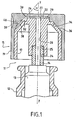
- a sprayer 11 comprising a bottle 12 in the mouth of which is installed a pump 13 manually actuating conventionally an outlet tube 14 through which the liquid under pressure is expelled when the tube is depressed via a push button 15 which is itself installed at the end of this tube.
- the push-button 15 has only two parts, namely an inner part 17 forcibly fitted to the end of the outlet tube 14 and an outer part 19 covering the inner part and forming a sort of decorative cap.
- the inner part 17 constitutes the support of the outer part.
- the two parts are made of molded plastic and are generally coaxial, their common axis yy confusing with that of the outlet tube 14, when the push button is installed at the end thereof.
- the two parts are nested one inside the other along the yy axis, without indexing.
- the inner part 17 comprises an axial conduit 20 opening in the center of an end face 22 thereof, perpendicular to the axis.
- the end of the axial duct which is remote from this end face comprises a widening 24, defining a shoulder 25, adapted to accommodate the end of the outlet tube 14, the mounting being done by force fitting.
- At least one transverse passage is defined between the end face 22 of the inner part and the inner face 27 facing the outer part 19. This transverse passage extends between the axial duct 20 and an annular supply chamber 30 defined between the two pieces. More specifically, the inner part has an annular shoulder 32 defined at the periphery of the end face 22 and extending opposite the inner face of the outer part. It is clear that the axial duct 20 communicates with the transverse passage 26 which opens itself into said annular supply chamber 30. Consequently, the liquid discharged by the pump invades this annular supply chamber.
- the end face of the inner part comprises at least one groove or rib 29, integrally molded and defining the transverse passage 26 between the faces 22 and 27, opposite.
- the two parts 17, 19 comprise faces 34, 36 inclined relative to their common axis and applying against each other.
- the inner inclined face 34 of the outer part 19 carries an impression 38 defining the greater part of a swirl chamber 39.
- the latter is closed by the external inclined face 36 of the inner part 17.
- the swirl chamber communicates with said annular feed chamber 30, as can be seen in FIG. 1.
- an ejection duct 40 for the sprayed liquid extends through the wall of the outer part 19; it opens internally in the center of said footprint 38.
- the ejection duct is perpendicular to the common axis of the two parts; it could also be perpendicular to the inclined face in which the impression is made.
- inclined face we mean more precisely a surface whose section passing through the common axis yy forms an acute angle ⁇ with this axis whose apex is outside and “forwards" with respect to the end face 22 or 27 perpendicular to this axis.
- This type of inclination is favorable to a release "in the axis" of the outer part having the impression, without deterioration of the latter.
- the angle ⁇ has a value of at least about 20 °, it is preferably chosen between 30 ° and 50 °.
- the inclined faces in contact 34, 36 of the two parts are frustoconical, which allows mounting without indexing.
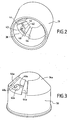
- Figures 2 and 3 provide a better understanding of the structure of the cavity 38 and its ability to be demolded easily "in the axis".
- the cavity comprises a recess 42 with a circular contour, concave or even frustoconical, centered on the internal orifice 43 of the ejection duct 40, two grooves 44 extending substantially parallel to a generator the frustoconical surface 34, on either side of said recess and two channels 46, 48 respectively extending between said recess and each groove 44.
- the two grooves 44 communicate with the annular supply chamber 30 and each channel 46, 48 opens substantially tangentially into the recess at substantially diametrically opposite points.
- each channel 46, 48 comprises two V-section flanks.
- the angle of the two flanks is 90 °.
- One of the flanks extends substantially perpendicularly to the common axis y-y, while the other extends substantially on a cylindrical surface centered on this axis.
- the channel 48 farthest from the annular chamber 30 has a larger section than the other channel 46. This section difference allows to rebalance the liquid swirl in the chamber 39 although the outlet duct 40 is not "perpendicular" to said chamber since it is instead perpendicular to the yy axis.
- FIG. 3 more particularly illustrates the element 50 of the mold which bears in relief the structural elements intended to constitute the impression 38.
- Two ribs 46a, 48a intended to form the channels 46, 48 extend between this frustoconical projection and the ribs 44a.
- the rib 48a has a larger section than the rib 46a.
Landscapes
- Chemical & Material Sciences (AREA)
- Dispersion Chemistry (AREA)
- Engineering & Computer Science (AREA)
- Mechanical Engineering (AREA)
- Containers And Packaging Bodies Having A Special Means To Remove Contents (AREA)
- Closures For Containers (AREA)
- Infusion, Injection, And Reservoir Apparatuses (AREA)
- Combustion Methods Of Internal-Combustion Engines (AREA)
- Nozzles (AREA)
- Pressure-Spray And Ultrasonic-Wave- Spray Burners (AREA)
- Disintegrating Or Milling (AREA)
- Crushing And Grinding (AREA)
Description
- L'invention se rapporte à un bouton-poussoir de pulvérisateur à sortie de pulvérisation latérale et concerne plus particulièrement un perfectionnement permettant de simplifier la structure de cet élément et notamment de réduire le nombre de pièces le constituant. L'invention vise également tout pulvérisateur à actionnement manuel muni d'une pompe comprenant un tel bouton-poussoir.
- Dans le domaine des pulvérisateurs à actionnement manuel, il est classique d'agencer une chambre de tourbillonnement dans le bouton-poussoir, immédiatement en amont du conduit d'éjection de liquide pulvérisé. Cette chambre de tourbillonnement à entrée périphérique et sortie centrale, communiquant avec ledit conduit d'éjection, a pour fonction de mettre le liquide expulsé par la pompe, en circulation rotative tourbillonnaire juste avant son éjection, ce qui provoque la pulvérisation.
- Le brevet FR 2 095 836 décrit un bouton-poussoir à sortie de pulvérisation latérale, composé principalement de deux pièces en matière plastique moulée, respectivement une pièce intérieure et une pièce extérieure formant coiffe, globalement coaxiales et emboîtées l'une dans l'autre. La pièce intérieure est raccordée à l'extrémité d'un tube de sortie de la pompe. Il est simplement emboîté à force sur celui-ci de sorte que l'ensemble du bouton-poussoir est porté par le tube de sortie de la pompe. Cette dernière est elle-même montée dans le col d'un flacon renfermant le produit à pulvériser.
- Dans ce bouton-poussoir, la chambre de tourbillonnement est réalisée au moulage par impression d'une empreinte à la surface latérale interne de la pièce extérieure au moyen d'un mécanisme interne de la pièce extérieure au moyen d'un mécanisme de matrice nécessairement volumineux et coûteux, difficile à mettre en oeuvre et très pénalisant du point de vue de la cadence de production. En outre, l'encombrement du mécanisme appelé à s'engager à l'intérieur de ladite pièce extérieure, rend ce procédé inapplicable à la fabrication d'un bouton-poussoir de petites dimensions. L'invention apporte une solution à cer ensemble de problèmes.
- L'idée de base de l'invention consiste à définir les éléments essentiels de la chambre de tourbillonnement par une empreinte formée au moulage sur la face interne de la pièce extérieure, autour de l'orifice intérieur du conduit d'éjection du liquide pulvérisé, sans avoir recours à un quelconque mécanisme de matrice mobile transversalement à l'intérieur du moule mais en faisant en sorte que le démoulage de ladite pièce extérieure puisse se faire "dans l'axe" sans pour autant endommager l'empreinte.
- Plus précisément, l'invention concerne un bouton-poussoir de pulvérisateur à sortie de pulvérisation latérale du type comportant une chambre de tourbillonnement à sortie centrale et entrée périphérique, agencée entre deux pièces moulées, globalement coaxiales, respectivement une pièce intérieure et une pièce extérieure, ces deux pièces étant emboîtées l'une dans l'autre, et une empreinte faisant partie de ladite chambre de tourbillonnement étant définie à l'intérieur de ladite pièce extérieure laquelle comporte en outre un conduit d'éjection s'étendant au travers de sa paroi à partir du centre de ladite empreinte, caractérisé en ce que lesdites deux pièces comportent des faces inclinées par rapport à leur axe commun d'emboîtement, s'appliquant l'une contre l'autre, en ce que ladite empreinte est pratiquée sur la face inclinée de ladite pièce extérieure et en ce que lèsdites faces inclinées sont orientées dans un sens et selon un angle suffisant, propres à rendre possible un démoulage de ladite pièce extérieure selon ledit axe commun sans endommager ladite empreinte.
- Dans la pratique, l'angle (α) défini ci-dessus, doit être supérieur à 20°, de préférence compris entre 30° et 50°.
- Avantageusement, les faces inclinées des deux pièces sont tronconiques, ce qui rend tout indexage superflu puisque la chambre de tourbillonnement est définie entièrement par l'empreinte pratiquée à la face interne de la pièce extérieure et par la partie de paroi tronconique de la face externe de la pièce intérieure venant s'appliquer en regard de cette empreinte.
- Pour l'alimentation de ladite chambré de tourbillonnement, on peut prévoir un épaulement annulaire à l'extrémité de ladite pièce intérieure, s'étendant entre une face d'extrémité de cette pièce et ladite face tronconique, ce qui a pour effet de définir, avec la pièce extérieure, une chambre d'alimentation annulaire. Par ailleurs, la pièce intérieure comporte un conduit axial dans lequel le liquide à pulvériser est refoulé par la pompe. Ce conduit axial débouche au centre de la face d'extrémité de la pièce intérieure et au moins un passage transversal est défini entre ladite face d'extrémité et la face interne en regard de la pièce extérieure. Ce passage transversal s'étend entre le conduit axial et la chambre d'alimentation annulaire. De préférence, il est défini par au moins une cannelure ou nervure venue de moulage avec la pièce intérieure et s'étendant sur la face d'extrémité de celle-ci. Le passage transversal est ainsi défini entre les deux faces d'extrémité en regard de la pièce extérieure et de la pièce intérieure. Bien entendu, un agencement comparable défini à la face interne de la pièce extérieure permettrait de définir le passage transversal.
- Classiquement, la pièce intérieure forme une sorte de support emboîté à force à l'extrémité du tube de sortie de la pompe à actionnement manuel, tandis que la pièce extérieure forme une sorte de coiffe décorative venant recouvrir le support.
- L'invention sera mieux comprise et d'autres avantages de celle-ci apparaîtront plus clairement à la lumière de la description qui va suivre d'un bouton-poussoir conforme à son principe, donnée uniquement à titre d'exemple et faite en référence aux dessins annexés, dans lesquels :
- la figure 1 est une vue en élévation et en coupe du bouton-poussoir monté à l'extrémité d'une pompe à actionnement manuel ;
- la figure 2 est une vue de détail en perspective de l'intérieur de la pièce extérieure, montrant l'empreinte de la chambre de tourbillonnement ; et
- la figure 3 est une vue en perspective de l'un des éléments du moule de ladite pièce extérieure.
- En considérant plus particulièrement la figure 1, on voit la partie supérieure d'un pulvérisateur 11 comprenant un flacon 12 dans l'embouchure duquel se trouve installée une pompe 13 à actionnement manuel comportant classiquement un tube de sortie 14 par lequel le liquide sous pression est expulsé lorsque le tube est enfoncé par l'intermédiaire d'un bouton-poussoir 15 qui est lui-même installé à l'extrémité de ce tube.
- Le bouton-poussoir 15 comporte seulement deux pièces, à savoir une pièce intérieure 17 emboîtée à force à l'extrémité du tube de sortie 14 et une pièce extérieure 19 recouvrant la pièce intérieure et formant une sorte de coiffe décorative. La pièce intérieure 17 constitue le support de la pièce extérieure. Les deux pièces sont en matière plastique moulée et sont globalement coaxiales, leur axe commun y-y se confondant avec celui du tube de sortie 14, lorsque le bouton-poussoir est installé à l'extrémité de celui-ci. Les deux pièces sont emboîtées l'une dans l'autre selon l'axe y-y, sans indexage. De façon classique, la pièce intérieure 17 comporte un conduit axial 20 débouchant au centre d'une face d'extrémité 22 de celle-ci, perpendiculaire à l'axe. L'extrémité du conduit axial qui est éloignée de cette face d'extrémité comporte un élargissement 24, définissant un épaulement 25, propre à accueillir l'extrémité du tube de sortie 14, le montage se faisant par emboîtement à force. Au moins un passage transversal est défini entre la face d'extrémité 22 de la pièce intérieure et la face interne 27 en regard de la pièce extérieure 19. Ce passage transversal s'étend entre le conduit axial 20 et une chambre d'alimentation annulaire 30 définie entre les deux pièces. Plus précisément, la pièce intérieure comporte un épaulement annulaire 32 défini à la périphérie de la face d'extrémité 22 et s'étendant en regard de la face interne de la pièce extérieure. Il est clair que le conduit axial 20 communique avec le passage transversal 26 qui débouche lui-même dans ladite chambre d'alimentation annulaire 30. Par conséquent, le liquide refoulé par la pompe envahit cette chambre d'alimentation annulaire.
- La face d'extrémité de la pièce intérieure comporte au moins une cannelure ou nervure 29, venue de moulage et définissant le passage transversal 26 entre les faces 22 et 27, en regard.
- Selon une caractéristique importante de l'invention, les deux pièces 17, 19 comportent des faces 34, 36 inclinées par rapport à leur axe commun et s'appliquant l'une contre l'autre. La face inclinée 34 interne de la pièce extérieure 19 porte une empreinte 38 définissant la plus grande partie d'une chambre de tourbillonnement 39. Cette dernière est fermée par la face inclinée externe 36 de la pièce intérieure 17. La chambre de tourbillonnement communique avec ladite chambre d'alimentation annulaire 30, comme cela est visible sur la figure 1. En outre, un conduit d'éjection 40 pour le liquide pulvérisé s'étend au travers de la paroi de la pièce extérieure 19 ; il débouche intérieurement au centre de ladite empreinte 38. Dans l'exemple, le conduit d'éjection est perpendiculaire à l'axe commun des deux pièces ; il pourrait aussi être perpendiculaire à la face inclinée dans laquelle est pratiquée l'empreinte. Par face inclinée, on entend plus précisément une surface dont une section passant par l'axe commun y-y forme un angle aigu α avec cet axe dont le sommet se trouve à l'extérieur et "vers l'avant" par rapport à la face d'extrémité 22 ou 27 perpendiculaire à cet axe. Ce type d'inclinaison est favorable à un démoulage "dans l'axe" de la pièce extérieure comportant l'empreinte, sans détérioration de cette dernière. Comme indiqué ci-dessus, l'angle α a une valeur d'au moins 20°, environ, il est de préférence choisi entre 30° et 50°.
- Selon une autre caractéristique avantageuse, les faces inclinées en contact 34, 36 des deux pièces sont tronconiques, ce qui permet un montage sans indexation.
- Les figures 2 et 3 permettent de mieux comprendre la structure de l'empreinte 38 et son aptitude à être démoulée facilement "dans l'axe". Sur la figure 2, on voit que l'empreinte comporte une creusure à contour circulaire 42, concave, voire tronconique, centrée sur l'orifice interne 43 du conduit d'éjection 40, deux rainures 44 s'étendant sensiblement parallèlement à une génératrice dé la surface tronconique 34, de part et d'autre de ladite creusure et deux canaux 46, 48 s'étendant respectivement entre ladite creusure et chaque rainure 44. Les deux rainures 44 communiquent avec la chambre d'alimentation annulaire 30 et chaque canal 46, 48 débouche sensiblement tangentiellement dans la creusure en des points sensiblement diamétralement opposés. De plus, chaque canal 46, 48 comporte deux flancs à section en V. Dans l'exemple, l'angle des deux flancs est de 90°. L'un des flancs s'étend sensiblement perpendiculairement à l'axe commun y-y, tandis que l'autre s'étend sensiblement sur une surface cylindrique centrée sur cet axe. Dans le cas où le conduit est, comme représenté ici, perpendiculaire à l'axe commun y-y des deux pièces, le canal 48 le plus éloigné de la chambre annulaire 30 a une section plus grande que l'autre canal 46. Cette différence de section permet de rééquilibrer le tourbillonnement de liquide dans la chambre 39 bien que le conduit de sortie 40 ne soit pas "perpendiculaire" à ladite chambre puisqu'il est au contraire perpendiculaire à l'axe y-y.
- La figure 3 illustre plus particulièrement l'élément 50 du moule qui porte en relief les éléments de structure destinés à constituer l'empreinte 38. On distingue deux nervures 44a destinées à former les rainures et s'étendant en relief sur une surface tronconique 34a de part et d'autre d'une saillie tronconique 42a destinée à former la creusure 42. Deux nervures 46a, 48a destinées à former les canaux 46, 48 s'étendent entre cette saillie tronconique et les nervures 44a. Bien entendu, la nervure 48a a une section plus importante que la nervure 46a.
Claims (10)
- Bouton-poussoir de pulvérisateur à sortie de pulvérisation latérale du type comportant une chambre de tourbillonnement (39) à sortie centrale et entrée périphérique, agencée entre deux pièces (17, 19) moulées, globalement coaxiales, respectivement une pièce intérieure (17) et une pièce extérieure (19), ces deux pièces étant emboîtées l'une dans l'autre, et une empreinte (38) faisant partie de ladite chambre de tourbillonnement étant définie à l'intérieur de ladite pièce extérieure laquelle comporte en outre un conduit d'éjection s'étendant au travers de sa paroi à partir du centre de ladite empreinte, lesdites deux pièces comportant des faces inclinées (34, 36) par rapport à leur axe commun d'emboîtement (y-y), s'appliquant l'une contre l'autre, en ce que ladite empreinte est pratiquée sur la face inclinée de ladite pièce extérieure caractérisé en ce que lesdites faces inclinées sont orientées dans un sens et selon un angle (α) suffisant, propres à rendre possible un démoulage de ladite pièce extérieure selon ledit axe commun sans endommager ladite empreinte qui comporte une creusure à contour circulaire (42) centrée sur l'orifice interne dudit conduit d'éjection, deux rainures (44) s'étendant sensiblement parallèlement à une génératrice de ladite surface cylindrique, de part et d'autre de ladite creusure et communiquant avec ladite chambre d'alimentation annulaire et des canaux (46, 48) s'étendant respectivement entre ladite creusure et chaque rainure et débouchant sensiblement tangentiellement dans ladite creusure et en ce que chaque canal (46, 48) comporte deux flancs à section en V ; l'un des flancs dudit canal s'étendant sensiblement perpendiculairement audit axe commun, tandis que l'autre s'étend sensiblement sur une surface cylindrique centrée sur cet axe.
- Bouton-poussoir selon la revendication 1, caractérisé en ce que lesdites faces inclinées (34, 36) des deux pièces sont tronconiques.
- Bouton-poussoir selon la revendication 2, caractérisé en ce que ladite pièce intérieure comporte un épaulement annulaire (32), définissant avec la pièce extérieure une chambre d'alimentation annulaire (30) s'étendant à la périphérie d'une face d'extrémité de ladite pièce intérieure et communiquant avec ladite chambre de tourbillonnement.
- Bouton-poussoir selon la revendication 3, caractérisé en ce que ladite pièce intérieure comporte un conduit axial (20) débouchant au centre de ladite face d'extrémité de ladite pièce intérieure et en ce qu'au moins un passage transversal (26) est défini entre ladite pièce extérieure, ledit passage transversal s'étendant entre ledit conduit axial et ladite chambre d'alimentation annulaire.
- Bouton-poussoir selon la revendication 4, en ce que ladite face d'extrémité de la pièce intérieure comporte au moins une cannelure ou nervure de moulage et définissant ledit passage transversal avec la face en regard de ladite pièce extérieure.
- Bouton-poussoir selon l'une des revendications 4 ou 5, caractérisé en ce que l'extrémité dudit conduit axial éloignée de ladite face d'extrémité comporte un élargissement propre à accueillir l'extrémité d'un tube de sortie d'un mécanisme de pompe.
- Bouton-poussoir selon l'une des revendications précédentes, carcatérisé en ce que ledit conduit d'éjection (40) est perpendiculaire audit axe commun des deux pièces.
- Bouton-poussoir selon la revendication 7, caractérisé en ce que le canal (48) le plus éloigné de ladite chambre annulaire a une section plus grande que l'autre.
- Bouton-poussoir selon l'une des revendications précédentes, caractérisé en ce que l'angle (α) précité est supérieur à 20°, de préférence compris entre 30° et 50°.
- Pulvérisateur équipé d'une pompe à actionnement manuel, caractérisé en ce qu'il comporte un bouton-poussoir selon l'une des revendications précédentes.
Applications Claiming Priority (2)
| Application Number | Priority Date | Filing Date | Title |
|---|---|---|---|
| FR0304418A FR2853635B1 (fr) | 2003-04-09 | 2003-04-09 | Bouton-poussoir de pulverisateur |
| PCT/EP2004/003801 WO2004089783A1 (fr) | 2003-04-09 | 2004-04-08 | Bouton-poussoir de pulvérisateur |
Publications (2)
| Publication Number | Publication Date |
|---|---|
| EP1613539A1 EP1613539A1 (fr) | 2006-01-11 |
| EP1613539B1 true EP1613539B1 (fr) | 2006-08-16 |
Family
ID=33041745
Family Applications (1)
| Application Number | Title | Priority Date | Filing Date |
|---|---|---|---|
| EP04726505A Expired - Lifetime EP1613539B1 (fr) | 2003-04-09 | 2004-04-08 | Bouton-poussoir de pulverisateur |
Country Status (12)
| Country | Link |
|---|---|
| US (1) | US7281674B2 (fr) |
| EP (1) | EP1613539B1 (fr) |
| JP (1) | JP4705016B2 (fr) |
| CN (1) | CN100457285C (fr) |
| AT (1) | ATE336446T1 (fr) |
| BR (1) | BRPI0409533A (fr) |
| CA (1) | CA2519704A1 (fr) |
| DE (1) | DE602004001987T2 (fr) |
| ES (1) | ES2270374T3 (fr) |
| FR (1) | FR2853635B1 (fr) |
| MX (1) | MXPA05010412A (fr) |
| WO (1) | WO2004089783A1 (fr) |
Cited By (2)
| Publication number | Priority date | Publication date | Assignee | Title |
|---|---|---|---|---|
| JP2006522676A (ja) * | 2003-04-09 | 2006-10-05 | レクサム ディスペンシング システムズ | 噴霧器に関するプッシュボタン |
| CN101143636B (zh) * | 2006-09-12 | 2011-05-18 | 雷克斯姆分配系统股份公司 | 流体产品的分配构件、包含并使用该分配构件的分配器 |
Families Citing this family (23)
| Publication number | Priority date | Publication date | Assignee | Title |
|---|---|---|---|---|
| FR2868709B1 (fr) | 2004-04-08 | 2006-06-23 | Rexam Dispensing Systems Sas | Distributeur sans reprise d'air pour la delivrance de faibles doses de produits liquides et, en particulier, de produits cosmetiques ou pharmaceutiques |
| NL1029746C2 (nl) * | 2005-08-16 | 2007-02-19 | Plasticum Group B V | Spuitbusmondstuk. |
| AU2007222673A1 (en) * | 2006-03-07 | 2007-09-13 | Boehringer Ingelheim International Gmbh | Swirl |
| EP2077132A1 (fr) | 2008-01-02 | 2009-07-08 | Boehringer Ingelheim Pharma GmbH & Co. KG | Dispositif distributeur, dispositif de stockage et procédé pour la distribution d'une formulation |
| FR2931136A1 (fr) * | 2008-05-14 | 2009-11-20 | Rexam Dispensing Systems Sas | Bouton poussoir a canaux de distribution convergents |
| EP2414560B1 (fr) | 2009-03-31 | 2013-10-23 | Boehringer Ingelheim International GmbH | Procédé de revêtement d'une surface d'un composant |
| EP3508239B1 (fr) | 2009-05-18 | 2020-12-23 | Boehringer Ingelheim International GmbH | Adaptateur, dispositif d'inhalation et pulvérisateur |
| MX2012005961A (es) | 2009-11-25 | 2012-06-14 | Boehringer Ingelheim Int | Nebulizador. |
| JP5658268B2 (ja) | 2009-11-25 | 2015-01-21 | ベーリンガー インゲルハイム インターナショナル ゲゼルシャフト ミット ベシュレンクテル ハフツング | ネブライザ |
| US10016568B2 (en) | 2009-11-25 | 2018-07-10 | Boehringer Ingelheim International Gmbh | Nebulizer |
| USD657242S1 (en) | 2010-01-14 | 2012-04-10 | S.C. Johnson & Son, Inc. | Container with nozzle |
| USD648216S1 (en) | 2010-01-14 | 2011-11-08 | S.C. Johnson & Son, Inc. | Actuator nozzle for a diffusion device |
| US20110259923A1 (en) * | 2010-04-26 | 2011-10-27 | John Geoffrey Chan | Plug And Valve System |
| JP5874724B2 (ja) | 2010-06-24 | 2016-03-02 | ベーリンガー インゲルハイム インターナショナル ゲゼルシャフト ミット ベシュレンクテル ハフツング | ネブライザ |
| WO2012130757A1 (fr) | 2011-04-01 | 2012-10-04 | Boehringer Ingelheim International Gmbh | Appareil médical pourvu d'un récipient |
| US9827384B2 (en) | 2011-05-23 | 2017-11-28 | Boehringer Ingelheim International Gmbh | Nebulizer |
| WO2013152894A1 (fr) | 2012-04-13 | 2013-10-17 | Boehringer Ingelheim International Gmbh | Pulvérisateur comprenant des moyens de détrompage |
| WO2015018904A1 (fr) | 2013-08-09 | 2015-02-12 | Boehringer Ingelheim International Gmbh | Nébuliseur |
| EP2835146B1 (fr) | 2013-08-09 | 2020-09-30 | Boehringer Ingelheim International GmbH | Atomiseur |
| BR122022010094B1 (pt) | 2014-05-07 | 2023-10-03 | Boehringer Ingelheim International Gmbh | Dispositivo indicador e recipiente |
| MX383195B (es) | 2014-05-07 | 2025-03-13 | Boehringer Ingelheim Int | Recipiente, nebulizador y uso. |
| WO2015169430A1 (fr) | 2014-05-07 | 2015-11-12 | Boehringer Ingelheim International Gmbh | Nébuliseur |
| JP7126254B2 (ja) * | 2018-10-02 | 2022-08-26 | 株式会社三谷バルブ | 内容物噴射ユニット |
Family Cites Families (9)
| Publication number | Priority date | Publication date | Assignee | Title |
|---|---|---|---|---|
| US3075708A (en) * | 1958-03-05 | 1963-01-29 | Drackett Co | One piece aerosol spray head |
| US3112074A (en) * | 1961-11-29 | 1963-11-26 | Edward Howard Green | Spray head for an aerosol dispenser |
| US3319894A (en) * | 1965-08-10 | 1967-05-16 | Diamond Int Corp | Liquid dispenser |
| NL145512C (fr) | 1970-06-12 | |||
| US3942725A (en) * | 1975-01-03 | 1976-03-09 | Green Edward | Sprayhead for swirling spray |
| JPS5831980B2 (ja) * | 1977-10-03 | 1983-07-09 | 東洋エアゾ−ル工業株式会社 | 噴霧器用押釦 |
| JPS62144560U (fr) * | 1986-03-07 | 1987-09-11 | ||
| US5593094A (en) * | 1995-02-07 | 1997-01-14 | Calmar Inc. | Pump sprayer having variable discharge |
| FR2853635B1 (fr) * | 2003-04-09 | 2007-04-06 | Rexam Dispensing Sys | Bouton-poussoir de pulverisateur |
-
2003
- 2003-04-09 FR FR0304418A patent/FR2853635B1/fr not_active Expired - Lifetime
-
2004
- 2004-04-08 WO PCT/EP2004/003801 patent/WO2004089783A1/fr not_active Ceased
- 2004-04-08 JP JP2006505083A patent/JP4705016B2/ja not_active Expired - Lifetime
- 2004-04-08 BR BRPI0409533-2A patent/BRPI0409533A/pt not_active IP Right Cessation
- 2004-04-08 AT AT04726505T patent/ATE336446T1/de not_active IP Right Cessation
- 2004-04-08 CN CNB2004800094925A patent/CN100457285C/zh not_active Expired - Fee Related
- 2004-04-08 MX MXPA05010412A patent/MXPA05010412A/es unknown
- 2004-04-08 CA CA002519704A patent/CA2519704A1/fr not_active Abandoned
- 2004-04-08 DE DE602004001987T patent/DE602004001987T2/de not_active Expired - Lifetime
- 2004-04-08 ES ES04726505T patent/ES2270374T3/es not_active Expired - Lifetime
- 2004-04-08 EP EP04726505A patent/EP1613539B1/fr not_active Expired - Lifetime
-
2005
- 2005-10-11 US US11/247,901 patent/US7281674B2/en not_active Expired - Lifetime
Cited By (2)
| Publication number | Priority date | Publication date | Assignee | Title |
|---|---|---|---|---|
| JP2006522676A (ja) * | 2003-04-09 | 2006-10-05 | レクサム ディスペンシング システムズ | 噴霧器に関するプッシュボタン |
| CN101143636B (zh) * | 2006-09-12 | 2011-05-18 | 雷克斯姆分配系统股份公司 | 流体产品的分配构件、包含并使用该分配构件的分配器 |
Also Published As
| Publication number | Publication date |
|---|---|
| US20060086828A1 (en) | 2006-04-27 |
| CA2519704A1 (fr) | 2004-10-21 |
| JP4705016B2 (ja) | 2011-06-22 |
| MXPA05010412A (es) | 2005-11-04 |
| WO2004089783A1 (fr) | 2004-10-21 |
| ES2270374T3 (es) | 2007-04-01 |
| FR2853635A1 (fr) | 2004-10-15 |
| CN100457285C (zh) | 2009-02-04 |
| JP2006522676A (ja) | 2006-10-05 |
| BRPI0409533A (pt) | 2006-04-18 |
| ATE336446T1 (de) | 2006-09-15 |
| DE602004001987D1 (de) | 2006-09-28 |
| CN1771172A (zh) | 2006-05-10 |
| DE602004001987T2 (de) | 2007-03-29 |
| FR2853635B1 (fr) | 2007-04-06 |
| US7281674B2 (en) | 2007-10-16 |
| EP1613539A1 (fr) | 2006-01-11 |
Similar Documents
| Publication | Publication Date | Title |
|---|---|---|
| EP1613539A1 (fr) | Bouton-poussoir de pulverisateur | |
| EP0802827B1 (fr) | Buse de pulverisation | |
| EP0494803B1 (fr) | Embout-poussoir à jets multiples et à fermeture | |
| EP0437131B1 (fr) | Pompe manuelle à précompression pour la pulvérisation d'un liquide, notamment d'un parfum | |
| FR2784717A1 (fr) | Pompe de faible capacite a compatibilite amelioree | |
| EP2579991B1 (fr) | Tete de distribution de produit fluide | |
| EP2258484B1 (fr) | Bouton poussoir pour un système de distribution d'un liquide sous pression | |
| WO2003066234A1 (fr) | Dispositif d' échantillons de parfum | |
| EP1054820B1 (fr) | Tete de pulverisation de pompe ou de valve | |
| EP1052191A1 (fr) | Récipient équipé d'une tête de distribution | |
| FR2713608A1 (fr) | Valve pour la distribution sous forme pulvérisée d'un liquide, et récipient pressurisé équipé d'une telle valve. | |
| EP0448467B1 (fr) | Poussoir à gicleur interne, avec projection latérale, pour pompe de pulvérisation à haute pression et à cadence rapide | |
| EP0663240B1 (fr) | Dispositif de distribution à pertes de charge réduites comportant une buse de distribution | |
| WO2004043827A1 (fr) | Dispositif de conditionnement et de distribution pour un produit liquide ou semi-liquide | |
| FR2708314A1 (fr) | Perfectionnements aux pompes doseuses. | |
| EP1677916A2 (fr) | Tete de pulverisation de produit fluide | |
| EP0561696B1 (fr) | Buse de distribution | |
| FR2752411A1 (fr) | Organe de fixation d'un dispositif de distribution sur un col d'un reservoir | |
| FR2860771A1 (fr) | Tete de distribution de produit fluide et procede de fabrication d'une telle tete | |
| FR2845623A1 (fr) | Pulverisateur a poussoir muni d'une buse laterale saillante | |
| FR2708908A1 (fr) | Bouton-poussoir à buse de pulvérisation destiné à être monté sur un distributeur et distributeur équipé d'un tel bouton-poussoir. | |
| FR2855159A1 (fr) | Tete de distribution montee ou faisant partie d'un organe de distribution de produit fluide | |
| FR2851483A1 (fr) | Tete de distribution | |
| CH443171A (fr) | Capuchon pour récipient à aérosols |
Legal Events
| Date | Code | Title | Description |
|---|---|---|---|
| PUAI | Public reference made under article 153(3) epc to a published international application that has entered the european phase |
Free format text: ORIGINAL CODE: 0009012 |
|
| GRAP | Despatch of communication of intention to grant a patent |
Free format text: ORIGINAL CODE: EPIDOSNIGR1 |
|
| 17P | Request for examination filed |
Effective date: 20050919 |
|
| AK | Designated contracting states |
Kind code of ref document: A1 Designated state(s): AT BE BG CH CY CZ DE DK EE ES FI FR GB GR HU IE IT LI LU MC NL PL PT RO SE SI SK TR |
|
| AX | Request for extension of the european patent |
Extension state: AL HR LT LV MK |
|
| DAX | Request for extension of the european patent (deleted) | ||
| GRAS | Grant fee paid |
Free format text: ORIGINAL CODE: EPIDOSNIGR3 |
|
| GRAA | (expected) grant |
Free format text: ORIGINAL CODE: 0009210 |
|
| AK | Designated contracting states |
Kind code of ref document: B1 Designated state(s): AT BE BG CH CY CZ DE DK EE ES FI FR GB GR HU IE IT LI LU MC NL PL PT RO SE SI SK TR |
|
| PG25 | Lapsed in a contracting state [announced via postgrant information from national office to epo] |
Ref country code: SI Free format text: LAPSE BECAUSE OF FAILURE TO SUBMIT A TRANSLATION OF THE DESCRIPTION OR TO PAY THE FEE WITHIN THE PRESCRIBED TIME-LIMIT Effective date: 20060816 Ref country code: IT Free format text: LAPSE BECAUSE OF FAILURE TO SUBMIT A TRANSLATION OF THE DESCRIPTION OR TO PAY THE FEE WITHIN THE PRESCRIBED TIME-LIMIT;WARNING: LAPSES OF ITALIAN PATENTS WITH EFFECTIVE DATE BEFORE 2007 MAY HAVE OCCURRED AT ANY TIME BEFORE 2007. THE CORRECT EFFECTIVE DATE MAY BE DIFFERENT FROM THE ONE RECORDED. Effective date: 20060816 Ref country code: RO Free format text: LAPSE BECAUSE OF FAILURE TO SUBMIT A TRANSLATION OF THE DESCRIPTION OR TO PAY THE FEE WITHIN THE PRESCRIBED TIME-LIMIT Effective date: 20060816 Ref country code: CZ Free format text: LAPSE BECAUSE OF FAILURE TO SUBMIT A TRANSLATION OF THE DESCRIPTION OR TO PAY THE FEE WITHIN THE PRESCRIBED TIME-LIMIT Effective date: 20060816 Ref country code: FI Free format text: LAPSE BECAUSE OF FAILURE TO SUBMIT A TRANSLATION OF THE DESCRIPTION OR TO PAY THE FEE WITHIN THE PRESCRIBED TIME-LIMIT Effective date: 20060816 Ref country code: NL Free format text: LAPSE BECAUSE OF FAILURE TO SUBMIT A TRANSLATION OF THE DESCRIPTION OR TO PAY THE FEE WITHIN THE PRESCRIBED TIME-LIMIT Effective date: 20060816 Ref country code: AT Free format text: LAPSE BECAUSE OF FAILURE TO SUBMIT A TRANSLATION OF THE DESCRIPTION OR TO PAY THE FEE WITHIN THE PRESCRIBED TIME-LIMIT Effective date: 20060816 Ref country code: IE Free format text: LAPSE BECAUSE OF FAILURE TO SUBMIT A TRANSLATION OF THE DESCRIPTION OR TO PAY THE FEE WITHIN THE PRESCRIBED TIME-LIMIT Effective date: 20060816 Ref country code: PL Free format text: LAPSE BECAUSE OF FAILURE TO SUBMIT A TRANSLATION OF THE DESCRIPTION OR TO PAY THE FEE WITHIN THE PRESCRIBED TIME-LIMIT Effective date: 20060816 Ref country code: SK Free format text: LAPSE BECAUSE OF FAILURE TO SUBMIT A TRANSLATION OF THE DESCRIPTION OR TO PAY THE FEE WITHIN THE PRESCRIBED TIME-LIMIT Effective date: 20060816 |
|
| REG | Reference to a national code |
Ref country code: GB Ref legal event code: FG4D Free format text: NOT ENGLISH |
|
| REG | Reference to a national code |
Ref country code: CH Ref legal event code: EP |
|
| REG | Reference to a national code |
Ref country code: IE Ref legal event code: FG4D Free format text: LANGUAGE OF EP DOCUMENT: FRENCH |
|
| REF | Corresponds to: |
Ref document number: 602004001987 Country of ref document: DE Date of ref document: 20060928 Kind code of ref document: P |
|
| REG | Reference to a national code |
Ref country code: DE Ref legal event code: R096 Ref document number: 602004001987 Country of ref document: DE Effective date: 20060928 |
|
| GBT | Gb: translation of ep patent filed (gb section 77(6)(a)/1977) |
Effective date: 20061016 |
|
| PG25 | Lapsed in a contracting state [announced via postgrant information from national office to epo] |
Ref country code: SE Free format text: LAPSE BECAUSE OF FAILURE TO SUBMIT A TRANSLATION OF THE DESCRIPTION OR TO PAY THE FEE WITHIN THE PRESCRIBED TIME-LIMIT Effective date: 20061116 Ref country code: DK Free format text: LAPSE BECAUSE OF FAILURE TO SUBMIT A TRANSLATION OF THE DESCRIPTION OR TO PAY THE FEE WITHIN THE PRESCRIBED TIME-LIMIT Effective date: 20061116 Ref country code: BG Free format text: LAPSE BECAUSE OF FAILURE TO SUBMIT A TRANSLATION OF THE DESCRIPTION OR TO PAY THE FEE WITHIN THE PRESCRIBED TIME-LIMIT Effective date: 20061116 |
|
| REG | Reference to a national code |
Ref country code: DE Ref legal event code: R079 Ref document number: 602004001987 Country of ref document: DE Free format text: PREVIOUS MAIN CLASS: B65D0083160000 Ipc: B65D0083140000 |
|
| PG25 | Lapsed in a contracting state [announced via postgrant information from national office to epo] |
Ref country code: PT Free format text: LAPSE BECAUSE OF FAILURE TO SUBMIT A TRANSLATION OF THE DESCRIPTION OR TO PAY THE FEE WITHIN THE PRESCRIBED TIME-LIMIT Effective date: 20070116 |
|
| NLV1 | Nl: lapsed or annulled due to failure to fulfill the requirements of art. 29p and 29m of the patents act | ||
| REG | Reference to a national code |
Ref country code: IE Ref legal event code: FD4D |
|
| REG | Reference to a national code |
Ref country code: ES Ref legal event code: FG2A Ref document number: 2270374 Country of ref document: ES Kind code of ref document: T3 |
|
| PLBE | No opposition filed within time limit |
Free format text: ORIGINAL CODE: 0009261 |
|
| STAA | Information on the status of an ep patent application or granted ep patent |
Free format text: STATUS: NO OPPOSITION FILED WITHIN TIME LIMIT |
|
| 26N | No opposition filed |
Effective date: 20070518 |
|
| REG | Reference to a national code |
Ref country code: DE Ref legal event code: R097 Ref document number: 602004001987 Country of ref document: DE Effective date: 20070518 |
|
| BERE | Be: lapsed |
Owner name: REXAM DISPENSING SYSTEMS Effective date: 20070430 |
|
| PG25 | Lapsed in a contracting state [announced via postgrant information from national office to epo] |
Ref country code: BE Free format text: LAPSE BECAUSE OF NON-PAYMENT OF DUE FEES Effective date: 20070430 |
|
| PG25 | Lapsed in a contracting state [announced via postgrant information from national office to epo] |
Ref country code: GR Free format text: LAPSE BECAUSE OF FAILURE TO SUBMIT A TRANSLATION OF THE DESCRIPTION OR TO PAY THE FEE WITHIN THE PRESCRIBED TIME-LIMIT Effective date: 20061117 |
|
| PG25 | Lapsed in a contracting state [announced via postgrant information from national office to epo] |
Ref country code: EE Free format text: LAPSE BECAUSE OF FAILURE TO SUBMIT A TRANSLATION OF THE DESCRIPTION OR TO PAY THE FEE WITHIN THE PRESCRIBED TIME-LIMIT Effective date: 20060816 |
|
| PGRI | Patent reinstated in contracting state [announced from national office to epo] |
Ref country code: IT Effective date: 20080601 |
|
| REG | Reference to a national code |
Ref country code: CH Ref legal event code: PL |
|
| PG25 | Lapsed in a contracting state [announced via postgrant information from national office to epo] |
Ref country code: LI Free format text: LAPSE BECAUSE OF NON-PAYMENT OF DUE FEES Effective date: 20080430 Ref country code: CH Free format text: LAPSE BECAUSE OF NON-PAYMENT OF DUE FEES Effective date: 20080430 |
|
| PG25 | Lapsed in a contracting state [announced via postgrant information from national office to epo] |
Ref country code: MC Free format text: LAPSE BECAUSE OF NON-PAYMENT OF DUE FEES Effective date: 20070430 |
|
| PG25 | Lapsed in a contracting state [announced via postgrant information from national office to epo] |
Ref country code: LU Free format text: LAPSE BECAUSE OF NON-PAYMENT OF DUE FEES Effective date: 20070408 Ref country code: CY Free format text: LAPSE BECAUSE OF FAILURE TO SUBMIT A TRANSLATION OF THE DESCRIPTION OR TO PAY THE FEE WITHIN THE PRESCRIBED TIME-LIMIT Effective date: 20060816 |
|
| PG25 | Lapsed in a contracting state [announced via postgrant information from national office to epo] |
Ref country code: HU Free format text: LAPSE BECAUSE OF FAILURE TO SUBMIT A TRANSLATION OF THE DESCRIPTION OR TO PAY THE FEE WITHIN THE PRESCRIBED TIME-LIMIT Effective date: 20070217 Ref country code: TR Free format text: LAPSE BECAUSE OF FAILURE TO SUBMIT A TRANSLATION OF THE DESCRIPTION OR TO PAY THE FEE WITHIN THE PRESCRIBED TIME-LIMIT Effective date: 20060816 |
|
| REG | Reference to a national code |
Ref country code: ES Ref legal event code: PC2A Owner name: ALBEA LE TREPORT, SOCIETE PAR ACTIONS SIMPLIFIEE Effective date: 20140617 |
|
| REG | Reference to a national code |
Ref country code: DE Ref legal event code: R082 Ref document number: 602004001987 Country of ref document: DE Representative=s name: ADARES PATENT- UND RECHTSANWAELTE REININGER & , DE |
|
| REG | Reference to a national code |
Ref country code: DE Ref legal event code: R081 Ref document number: 602004001987 Country of ref document: DE Owner name: ALBEA LE TREPORT, FR Free format text: FORMER OWNER: REXAM DISPENSING SYSTEMS, LE TREPORT, FR Effective date: 20140702 Ref country code: DE Ref legal event code: R082 Ref document number: 602004001987 Country of ref document: DE Representative=s name: ADARES PATENT- UND RECHTSANWAELTE REININGER & , DE Effective date: 20140702 |
|
| REG | Reference to a national code |
Ref country code: FR Ref legal event code: CD Owner name: ALBEA LE TREPORT, FR Effective date: 20140822 |
|
| REG | Reference to a national code |
Ref country code: FR Ref legal event code: PLFP Year of fee payment: 12 |
|
| REG | Reference to a national code |
Ref country code: FR Ref legal event code: PLFP Year of fee payment: 13 |
|
| REG | Reference to a national code |
Ref country code: FR Ref legal event code: PLFP Year of fee payment: 14 |
|
| REG | Reference to a national code |
Ref country code: FR Ref legal event code: PLFP Year of fee payment: 15 |
|
| REG | Reference to a national code |
Ref country code: DE Ref legal event code: R082 Ref document number: 602004001987 Country of ref document: DE Representative=s name: ADARES PATENT- UND RECHTSANWAELTE REININGER & , DE |
|
| PGFP | Annual fee paid to national office [announced via postgrant information from national office to epo] |
Ref country code: DE Payment date: 20210428 Year of fee payment: 18 Ref country code: IT Payment date: 20210421 Year of fee payment: 18 |
|
| PGFP | Annual fee paid to national office [announced via postgrant information from national office to epo] |
Ref country code: ES Payment date: 20210504 Year of fee payment: 18 |
|
| REG | Reference to a national code |
Ref country code: DE Ref legal event code: R119 Ref document number: 602004001987 Country of ref document: DE |
|
| PG25 | Lapsed in a contracting state [announced via postgrant information from national office to epo] |
Ref country code: DE Free format text: LAPSE BECAUSE OF NON-PAYMENT OF DUE FEES Effective date: 20221103 |
|
| REG | Reference to a national code |
Ref country code: ES Ref legal event code: FD2A Effective date: 20230526 |
|
| PG25 | Lapsed in a contracting state [announced via postgrant information from national office to epo] |
Ref country code: IT Free format text: LAPSE BECAUSE OF FAILURE TO SUBMIT A TRANSLATION OF THE DESCRIPTION OR TO PAY THE FEE WITHIN THE PRESCRIBED TIME-LIMIT Effective date: 20220408 |
|
| PG25 | Lapsed in a contracting state [announced via postgrant information from national office to epo] |
Ref country code: ES Free format text: LAPSE BECAUSE OF NON-PAYMENT OF DUE FEES Effective date: 20220409 |
|
| PGFP | Annual fee paid to national office [announced via postgrant information from national office to epo] |
Ref country code: FR Payment date: 20230425 Year of fee payment: 20 |
|
| PGFP | Annual fee paid to national office [announced via postgrant information from national office to epo] |
Ref country code: GB Payment date: 20230427 Year of fee payment: 20 |
|
| REG | Reference to a national code |
Ref country code: GB Ref legal event code: PE20 Expiry date: 20240407 |
|
| PG25 | Lapsed in a contracting state [announced via postgrant information from national office to epo] |
Ref country code: GB Free format text: LAPSE BECAUSE OF EXPIRATION OF PROTECTION Effective date: 20240407 |
|
| PG25 | Lapsed in a contracting state [announced via postgrant information from national office to epo] |
Ref country code: GB Free format text: LAPSE BECAUSE OF EXPIRATION OF PROTECTION Effective date: 20240407 |