EP1612824B1 - Beleuchteter Bedienungsgriff zur Benutzung mit Schalter - Google Patents
Beleuchteter Bedienungsgriff zur Benutzung mit Schalter Download PDFInfo
- Publication number
- EP1612824B1 EP1612824B1 EP05014207A EP05014207A EP1612824B1 EP 1612824 B1 EP1612824 B1 EP 1612824B1 EP 05014207 A EP05014207 A EP 05014207A EP 05014207 A EP05014207 A EP 05014207A EP 1612824 B1 EP1612824 B1 EP 1612824B1
- Authority
- EP
- European Patent Office
- Prior art keywords
- handle
- cam
- activation
- contact
- extension
- Prior art date
- Legal status (The legal status is an assumption and is not a legal conclusion. Google has not performed a legal analysis and makes no representation as to the accuracy of the status listed.)
- Active
Links
Images


Classifications
-
- H—ELECTRICITY
- H01—ELECTRIC ELEMENTS
- H01H—ELECTRIC SWITCHES; RELAYS; SELECTORS; EMERGENCY PROTECTIVE DEVICES
- H01H71/00—Details of the protective switches or relays covered by groups H01H73/00 - H01H83/00
- H01H71/04—Means for indicating condition of the switching device
-
- H—ELECTRICITY
- H01—ELECTRIC ELEMENTS
- H01H—ELECTRIC SWITCHES; RELAYS; SELECTORS; EMERGENCY PROTECTIVE DEVICES
- H01H71/00—Details of the protective switches or relays covered by groups H01H73/00 - H01H83/00
- H01H71/10—Operating or release mechanisms
- H01H71/12—Automatic release mechanisms with or without manual release
- H01H71/46—Automatic release mechanisms with or without manual release having means for operating auxiliary contacts additional to the main contacts
-
- H—ELECTRICITY
- H01—ELECTRIC ELEMENTS
- H01H—ELECTRIC SWITCHES; RELAYS; SELECTORS; EMERGENCY PROTECTIVE DEVICES
- H01H11/00—Apparatus or processes specially adapted for the manufacture of electric switches
- H01H11/0006—Apparatus or processes specially adapted for the manufacture of electric switches for converting electric switches
-
- H—ELECTRICITY
- H01—ELECTRIC ELEMENTS
- H01H—ELECTRIC SWITCHES; RELAYS; SELECTORS; EMERGENCY PROTECTIVE DEVICES
- H01H73/00—Protective overload circuit-breaking switches in which excess current opens the contacts by automatic release of mechanical energy stored by previous operation of a hand reset mechanism
- H01H73/02—Details
- H01H73/12—Means for indicating condition of the switch
- H01H73/14—Indicating lamp structurally associated with the switch
-
- H—ELECTRICITY
- H01—ELECTRIC ELEMENTS
- H01H—ELECTRIC SWITCHES; RELAYS; SELECTORS; EMERGENCY PROTECTIVE DEVICES
- H01H9/00—Details of switching devices, not covered by groups H01H1/00 - H01H7/00
- H01H9/0066—Auxiliary contact devices
-
- H—ELECTRICITY
- H01—ELECTRIC ELEMENTS
- H01H—ELECTRIC SWITCHES; RELAYS; SELECTORS; EMERGENCY PROTECTIVE DEVICES
- H01H9/00—Details of switching devices, not covered by groups H01H1/00 - H01H7/00
- H01H9/16—Indicators for switching condition, e.g. "on" or "off"
- H01H9/161—Indicators for switching condition, e.g. "on" or "off" comprising light emitting elements
- H01H9/162—Means to facilitate removal or replacement of light-emitting elements
Definitions
- the present invention relates to electrical circuit disconnecting means (CDM) for mounting in cabinets and having a forwardly-extending, rotary disconnect that engages a handle on a cabinet door when the cabinet door is closed, and in particular to an improvement in such CDM that provide visual indications of assembly states outside the cabinet as well as provide auxiliary contacts within the cabinet that are controllable irrespective of the position of the door.
- CDM electrical circuit disconnecting means
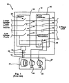
- a standard breaker assembly 10 of the prior art includes several components mounted within a cabinet 12 including a door 20 and several components mounted to the door 20.
- the components within the cabinet include a circuit breaker 16, a power contactor 18 and a disconnector or disconnect means 33.
- Circuit breaker 16 is a three phase breaker including three switches 25, 26 and 58 as well as an auxiliary switch 29.
- Contactor 18 includes three power contacts 56, 50 and 42, a relay coil 44 and two control or auxiliary contacts 51 and 54. Contacts 56, 50, 42 and 54 are normally open while contact 51 is normally closed.
- Three phase high voltage power is provided to breaker 16, a separate phase provided to each of switches 25, 26 and 58.
- single phase low voltage power is provided to switch 29 as well as to each of auxiliary contacts 51 and 54.
- Each of switches 25, 26 and 58 is linked in series with a separate one of power contacts 56, 50 and 42 while auxiliary switch 29 is linked in series with coil 44.
- the output of each power contact 56, 50 and 42 feeds a different phase of a three phase load (e.g., a motor).
- Each of power contacts 56, 50 and 42 as well as auxiliary contacts 51 and 54 is controlled by relay coil 44 such that, when coil 44 is deenergized, the contacts assume their normal condition and, when coil 44 is energized, the contacts transition to their exited states (i.e., normally open contacts close and normally closed contacts open).
- breaker 16 is automatically controlled as a function of system operating parameters to either close switches 25, 26 and 58 thereby providing power to contactor 18 and to close switch 29 thereby exciting coil 44 and in turn transitioning contacts 56, 50, 42, 51 and 534 or to open switches 25, 26, 58 and 29 thereby cutting off power to contactor 18 and de-energizing coil 44.
- components in the illustrated example that are mounted to cabinet door 20 include a handle member or handle 24 and "On" and “Off” lights 60 and 22, respectively.
- On light 60 is linked to auxiliary contact 54 and lights up when contact 54 is closed.
- light 22 is linked to contact 51 and lights up when contact 51 is closed.
- Manual disconnector 33 is a mechanical assembly that links to handle 24 and that can be used to manually open the switches in breaker 16.
- a shaft 30 extends from breaker 16 toward door 20 and is rotatable about its axis of extension to electrically open and close breaker switches 25, 26, 58 and 29.
- Handle 24 is configured to engage the distal end 31 of shaft 30.
- a pair of cylindrical locking pins 34 extends horizontally outwardly from either side of the distal end 31 of shaft 30.
- An extension member 32 extends from the rear side of handle 24 through an opening in door 20, forms a corresponding keyhole 36 that faces into cabinet 12 and includes a first horizontally extending slot 38 sized to receive locking pins 34.
- Key hole 36 further includes a second vertically extending slot 40 that intersects with slot 38 and is sized to receive the outer end 31 of shaft 30.
- the breaker 16 may includes many more switches and/or may feed additional contactors or other relay components.
- additional auxiliary contacts may be provided as well as additional lights to indicate other system and component transitional states.
- the assembly has several shortcomings.
- Figs. 1 and 2 assume that attempts to provide power from the supply lines to the load through cabinet 12 have failed.
- a system operator may attempt transitioning the assembly components and listen for audible tell tale signs of what is going on inside the cabinet.
- audible noise from the closed cabinet is often difficult to ascribe to the various components mounted therein when the door is closed.
- Another solution for determining the source of failure is to open up the cabinet door 20 and visually inspect the components inside the cabinet 12. Consistent with the description above, to open door 20, a system operator turns handle 24 and disconnector 33 to the off position thereby cutting power to contactor 18 and to coil 44. Thereafter, the operator opens door 20 to observe and inspect the components mounted in cabinet 12. While some failures result in easily observable damage to components, in many cases failures do not cause visually recognizable damage. For instance, in some cases normally open power contactor contacts may stick or fuse closed and the fused contacts may not be positioned in any easy to observe orientation or, the source of the sticking may not be readily visually observable. In other cases additional relay contacts may be stuck in abnormal transitional states. In still other cases one or more of the lights (e.g., 60, 22, etc.) used to indicate handle and system states may be burnt out.
- the lights e.g., 60, 22, etc.
- Still one other solution for identifying the source of failure is to cause the cabinet mounted components to transition between states while the cabinet door is open.
- a system operator may use a pliers or the like to manually rotate shaft 30 into the On state wherein switches 25, 26, 58 and 29 are closed at which time coil 44 should excite and transition contacts 56, 50, 42, 51 and 54.
- a noise can typically be heard (e.g., "ker klunk") which is recognizable as a state transition.
- the user can transition the breaker again by turning the shaft in the opposite direction to the Off position.
- the assembly described above requires many parts, requires a good deal of time and labor to configure and therefore is relatively expensive. For instance, three separate holes have to be formed in door 20 to mount handle 24 and lights 60 and 22 and then each of those components have to be separately mounted. In many cases the mounting structure for each of the components includes several screws or the like. Exacerbating matters, many breaker assemblies will include several additional lights and control tools such as buttons, knobs, etc, each of the control tools requiring its own door hole or holes to accommodate mounting assemblies. As another instance, after lights are mounted to door 20, wiring has to be run form the lights to the associated auxiliary contacts and power source which increases configuration costs and time considerably.
- breaker assemblies cannot be easily modified to alter assembly functionality.
- a system operator wants to modify the auxiliary contact logic so that light 60 marked in Fig. 1 as "On” instead illuminates when the handle is in a tripped position, the operator has to rewire light 60 to other system components and, in fact, may also have to add additional components (e.g., another relay) to the assembly.
- a handle assembly may be provided for interacting with a circuit disconnect means where the handle assembly includes auxiliary contacts that are activated by the handle assembly movement itself and independently of the state of the disconnect means.
- the handle mounted auxiliary contacts can be used to control and test control circuitry within the cabinet with the cabinet door open or closed by placing one or more of the handle controlled contacts in control circuits.
- the auxiliary contacts can be linked to lights that reside on the external surface of a cabinet door so that contact state can be visually identified.
- the contacts can be used as trip indication contacts (e.g., linked to trip lights), on/off status contacts (e.g., linked to on/off lights), etc.
- one or more lights can be provided as integral parts of a handle assembly thereby reducing the costs associated with assemblies that require both a handle and one or more lights as well as reducing the amount of labor required to assemble the assembly.
- electricity can be provided to the lights through the same door opening through which the handle extends to link to the disconnect means.
- both lights and auxiliary contacts can be provided as part of a disconnect handle assembly and additional functionality can be provided.
- the contacts may be linked in series with the lights to indicate handle positions.
- some of the lights may be linked to the handle mounted auxiliary contacts while other lights are linked to contacts within the control circuitry in the cabinet.
- Other configurations are contemplated.
- At least some inventive embodiments include an apparatus for use with a control assembly including a power source and a circuit disconnector located on a first side of a planar member forming an opening, the disconnector including a first mechanical linkage having open and closed positions, the apparatus for manipulating the mechanical linkage between the open and closed positions and visually indicating on a second side of the planar member at least a first state of the control assembly when the first state occurs, the apparatus comprising a handle assembly including a handle member moveable between at least first and second positions and positioned on the second side of the planar member adjacent the opening, an extension member rigidly connected to and extending from the handle member through the opening and forming a second mechanical linkage at a distal end that is linkable with the first mechanical linkage on the first side of the planar member, the extension member moving the first mechanical linkage between the closed and open positions when the handle is moved between the first and second positions, respectively and at least a first light emitter positioned on the second side of the planar member and at least a
- some embodiments include a handle assembly for use with a control assembly including a power source and a circuit disconnector located on a first side of a planar member forming an opening, the disconnector including a first mechanical linkage having open and closed positions, the assembly comprising a handle member moveable between at least first and second positions and positioned on the second side of the planar member adjacent the opening, an extension member rigidly connected to and extending from the handle member through the opening and forming a second mechanical linkage at a distal end that is linkable with the first mechanical linkage on the first side of the planar member, the extension member moving the first mechanical linkage between the closed and open positions when the handle is moved between the first and second positions, respectively and at least a first light emitter positioned on the second side of the planar member and including conducting leads that extend from the first side to the second side of the planar member.
- some embodiments include a handle assembly for use with a control assembly including a circuit disconnector located on a first side of a planar member forming an opening, the disconnector including a first mechanical linkage having open and closed positions, the assembly comprising a handle member moveable between at least first and second positions and mounted on the second side of the planar member adjacent the opening, an extension member rigidly connected to and extending from the handle member through the opening and forming a second mechanical linkage at a distal end that is linkable with the first mechanical linkage, the extension member moving the first mechanical linkage between the closed and open positions when the handle is moved between the first and second positions, respectively, a cam at least linkable to the extension member for movement therewith on the first side of the planar member and at least a first contact including a activation member, the first contact closing when the activation member is activated, the cam, extension member and activation member positionable in a first relative juxtaposition with respect to each other such that when the handle member is in one of the first and second positions, the cam activates
- Fig. 1 is a schematic diagram illustrating a prior art breaker block assembly
- Fig. 2 is a partial perspective view of the linking portions of a handle and a disconnect shaft as known in the prior art
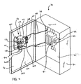
- Fig. 3 is a perspective view of a circuit breaker block including a handle assembly consistent with certain aspects of the present invention
- Fig. 4 is a perspective view of the assembly of Fig. 3 , albeit with a cabinet door in an open position;
- Fig. 5 is a front plan view of the handle assembly of Fig. 3 ;
- Fig. 6 is a rear plan view of the handle assembly of Fig. 4 ;
- Fig. 7 is an exploded view of the handle assembly of Figs. 4 and 5 ;
- Fig. 8 is an exploded view similar to the view of Fig. 7 , albeit from a different vantage point;
- Fig. 9 is a cross-sectional view of the handle assembly of Fig. 5 taken along the line 9-9;
- Fig 10 is a cross-sectional view of the handle assembly of Fig. 5 taken along the line 10-10;
- Fig 11 is a cross-sectional view of the handle assembly of Fig. 6 taken along the line 11-11;
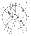
- Fig 12 is a plan view of the cam member of Fig. 7 ;
- Fig 13 is a similar to Fig. 12 , albeit illustrating a second cam member embodiment in a first juxtaposition;
- Fig 14 is similar to Fig 13 , except that the cam member is in a second relative juxtaposition;
- Fig 15 is a diagram similar to that illustrated in Fig 1 , albeit showing one handle assembly embodiment consistent with certain aspects of the present invention.
- FIG. 1 An exemplary breaker block 70 including a rigid metallic cabinet 71, a cabinet door 72, a breaker assembly 78, a mechanical disconnect assembly 99 and an inventive handle assembly identified generally by numeral 76.
- Cabinet 71 is a rectilinear box including a back wall 74 opposite an open front face.
- three-phase power is provided to cabinet 71 via three supply lines (not labeled) and three supply lines exit cabinet 71 and are linked to a load.
- Breaker assembly 78 as illustrated in Fig.
- breaker 416 includes three breaker switches 425, 426 and 458 while power contactor 418 includes a contactor coil 444 and three power contacts 456, 450 and 442.
- Switch 425 and contact 456 are linked in series in a first of the three power phases.
- switch 426 and contact 450 are linked in series with the second of the three power phases and switch 458 and contact 442 are linked in series with the third of the three power phases.
- Contacts 456, 450 and 442 are each normally open contacts.
- disconnect assembly 99 includes a shaft 80 that extends from breaker 416 toward door 72 and is rotatable about its axis of extension to electrically open and close breaker switches 425, 426 and 458.
- An internal or distal end 160 of a handle assembly extension member 100 is keyed so as to receive and be linkable to distal end 81 of shaft 80.
- keyed distal end 160 links to shaft end 81 and latches thereto will not be described in detail. It should suffice to say that the cooperating ends 160 and 81 latch together in a manner similar to that described above with respect to Fig.
- shaft 80 likewise rotates.
- handle assembly 76 can be manipulated to separate ends 160 and 81 so that door 72 can be opened.
- distal end 160 is latched to end 81 and handle assembly 76 cannot be manipulated to de-latch ends 160 and 81 until the breaker switches are open.
- handle assembly 76 various aspects of the present invention are related to the construction and operation of handle assembly 76.
- one inventive aspect of handle assembly 76 is that one or more light emitters 140, 142, 144 and 146 are provided via the handle assembly 76 itself.
- an esthetically pleasing assembly design results where lights to annunciate handle or breaker block status and the handle mechanism are provided in a relatively compact and elegant package.
- only a single hole has to be made in cabinet door 72 to mount components that previously required several holes.
- a single handle assembly including a handle and four lights can be mounted in a single door hole and electrical leads for all four lights can pass through the single hole along with the handle component that mechanically links to the disconnect assembly shaft 80.
- a simplified mounting configuration will be employed to mount the inventive handle assembly.
- a single nut may be provided to secure the entire handle assembly to the door.
- one or more auxiliary contacts 108, 110, 112, 114, etc. may be provided as part of the handle assembly 76 itself that are controllable to transition between closed and open states directly via manipulation of the assembly 76 as opposed to indirectly through the disconnect assembly 99.
- handle member 90 directly controls the state of the auxiliary contacts that comprise part of the handle assembly 76
- the handle assembly 76 can be used to transition the states of the contacts independent of whether or not door 72 is open or closed (i.e., independent of whether or not the handle assembly 76 is linked or delinked from disconnector shaft 80 (see again Fig. 4 )).
- auxiliary contacts that are directly controlled by handle assembly manipulation
- various useful control circuits can be configured.
- one of the handle assembly auxiliary contacts 114 may be provided in series with contactor coil 444 so that, when handle assembly 76 is manipulated into the ON position, handle assembly 76 directly closes contact 114 thereby providing power to coil 444 despite the fact that breaker 416 remains open.
- contactor contacts 456, 450 and 442 transition to their closed states.
- handle assembly 76 can be manipulated into the OFF position thereby causing contactor 114 to open cutting off power to coil 444 and transitioning contactor 418 between the closed and open states.
- one or more auxiliary contacts that change state as a function of handle position may be linked to one or more of the handle assembly lights so that handle positions are easily visually detectable from various distances.
- a handle assembly 76 includes ON and OFF positions (see 216 and 212, respectively)
- one of the contacts 114 may be configured and positioned to be activated when handle assembly 76 is in the OFF position and may be wired in series with a red emitting OFF light 140.
- a second handle assembly contact 112 may be configured and positioned to be activated when handle assembly 76 is in the ON position and may be wired in series with a green emitting ON light 142.
- handle assembly positions e.g., TRIP - see 214, RESET - see 210, etc.
- handle lights may also be annunciated via handle lights.
- auxiliary contacts 108, 110, 112, and 114 are positioned in series with other assembly components (e.g., trip indicating lights, on/off lights, etc.) and, indeed, where at least one and, in many cases, more than one of the auxiliary contacts may not be linked to other block components.
- handle assembly lights may include both handle assembly lights as well as handle assembly auxiliary contacts
- at least some embodiments will include lights and no handle assembly contacts while others will include handle assembly contacts and no handle assembly lights.
- the handle assembly contacts may be used in conjunction with other light devices mounted to cabinet door 72 or otherwise to communicate states/positions.
- the handle assembly lights may be used in conjunction with other contacts in block 70 to indicate states.
- handle assembly 76 includes a plurality of components arranged about an assembly axis 89.
- the assembly components include a handle member 90, a locking member 92, an intermediate member 94, a handle base member 96, an extension member 100, a light module 98, a cam member 102, a mounting member 104, a coupling member in the form of a single nut 106 and first through fourth auxiliary contacts 108, 110, 112 and 114, respectively.
- handle assembly components to be described herein already have relatively complex mechanical structure which operates to facilitate various functions and which is generally well known in the art. Because much of the component structure is well known, much of the detailed structure of the components will not be described in detail. For instance, various structural aspects of handle member 90, locking member 92, intermediate member 94, extension member 100 and base member 96 cooperate to limit movement of handle member 90 to a small number (e.g., 2-4) of positions such as ON and OFF positions and to allow locking member 92 to be positioned so as to lock handle member 90 in the OFF position. The structure that limits handle movement and facilitates locking is known and hence will not be described in detail.
- handle member 90 includes a round disk shaped member 122 and a grip member 120 that is integrally formed with disk member 122 and extends to one side thereof.
- Grip member 120 forms one pointed end 121 and an opposite generally rounded end 123.
- Pointed end 121 aligns with indicia (e.g., ON, OFF, TRIP, etc.) on a front surface 124 of base member 96 to indicate handle position.
- a slot shaped channel 125 is formed in disk member 122 and grip member 120 and a front surface 117 of grip member 120 forms a recess 113 such that slot 125 opens into recess 113.
- Locking member 92 is generally a flat rigid member having a receivable components 126 that, as its label implies, is received within channel 125 formed by handle member 90 and that is accessible within recess 113 when received in slot 125.
- Receivable component 126 forms an aperture 127 that extends therethrough.
- extension members 129 and 131 extend laterally in opposite directions. Extension members 129 and 131 limit the extent to which locking member 92 and, more specifically, component 126, is received within slot channel 125.
- a spring (not illustrated) is provided between extension members 129 and 131 and oppositely facing surfaces of member 90 thereby biasing component 126 into a recessed position with respect to handle member 90.
- this spring force can be overcome by gripping the portion of member 126 that is accessible through recess 113 and pulling member 126 against the force of the spring until aperture 127 is observable within recess 113.
- a padlock or the like can be used to lock member 92 in the extended position.
- the structure of the handle assembly components is such that locking member 92 can only be pulled to its locking position when handle member 90 is in an OFF position and cannot be pulled into its locking position when handle 90 is in an ON position.
- the assembly component structures are such that, when locking member 92 is in its extended and locking positions, handle member 90 cannot be rotated from the OFF position (hence the label "locking member") to the ON or any other position.
- Intermediate member 94 includes a slot end 97 and a distal extending end 95.
- Slot end 97 is formed to receive the portion of locking member 92 opposite component 126 and to enable sliding motion thereof along the assembly axis 89.
- Distal end 95 extends opposite slot end 97.
- extension member 100 includes a proximal end 161 and a distal end 160.
- Proximal end 161 receives end 95 of intermediate member 94 and links thereto in a manner known in the art.
- Proximal end 161 forms a flange 87 that extends laterally to a greater radius than other parts of member 100.
- Distal end 160 includes an external surface that is at least in part threaded.
- Intermediate flange 87 and the threaded surface proximate end 160, member 100 forms two laterally extending ribs 163 and 165 that extend in opposite directions laterally from the main section of member 100.
- Ribs 163 and 165 are provided to lock with recesses 179 and 186 in cam member 102 to be described in greater detail below.
- Base member 96 is a rigid generally rectilinear member having a front surface 124 and an oppositely facing rear surface 134.
- Member 96 forms a central circular opening generally identified by numeral 128 and forms various structural components within opening 128 that operate with mechanical features of locking member 92, intermediate member 94 and extension member 100 to restrict handle 90 movement to only certain positions and to facilitate the locking functionality described above.
- indicia is provided on front surface 124 that is juxtaposed with respect to structure 130 in opening 128 such that the indicia is aligned with pointed end 121 of handle member 90 when handle assembly 76 is in a position associated with the specific indicia.
- Light module 98 includes a generally square plate member 138 that has a rib 136 around its circumference and that forms a central circular hole 150 sized to pass distal end 160 of extension member 100. Rib 136 and plate 138 generally form a cavity 137 for receiving the rear surface 134 of base member 96. Lights 140 , 142, 144 and 146 are provided in rib 136. The lights may take any of several different forms including incandescent light bulbs, LEDs, etc., and may be provided in any of several different arrangements including a single light, multiple lights along one edge of rib 136, lights along opposite edges of rib 136, etc. In the illustrated embodiment a separate light is provided in each of the four rib edges.
- each of the lights may emit the same color light, in at least some embodiments it is contemplated that each light may emit a different color light (e.g., red, green, yellow, blue, etc.) where each color would be associated or associable with a different handle assembly state or a different state of the breaker assembly 70.
- a different color light e.g., red, green, yellow, blue, etc.
- an eight pin electrical port 158 is formed in a rear surface 152 just below opening 150.
- a separate pair of electrical conductors or leads 230 extends from port 158 to each of lights 140, 142, 144 and 146.
- leads 230 are potted within plate member 138 although other accommodating configurations are contemplated.
- two aligning pegs 154 and 156 extend perpendicular to rear surface 152 of light module 98. Pegs 154 and 156 are received within holes formed in door 72 to facilitate alignment of components on the inside and the outside of the door 72.
- door 72 forms an opening 170 through which distal end 160 of extension member 100 extends.
- An eight pin male connector (see 196 in Fig 7 ) that extends from mounting member 104 also extends through opening 170.
- Aligning holes 211 are provided on opposite sides of opening 170 which receive pegs 154 and 156 to align handle assembly components on both internal door surface 84 and external door surface 82.
- cam member 102 is a disk shaped member forming a central circular opening 183.
- Two laterally extending recesses 184 and 186 are formed in opening 183 that are generally of small arc and that open in opposite directions from recess 183.
- Recesses 184 and 186 are sized, dimensioned and juxtaposed such that when distal end 160 of extension member 100 extends through opening 183, ribs 163 and 165 are journalled within recesses 184 and 185, respectively, so that, when extension member 100 is rotated about assembly axis 89, cam member 102 similarly rotates.
- a radial slot 185 is formed to one side of opening 183 to pass male connector 196 that extend from mounting member 104 so that the distal end of the connector 196 can be linked to port 158 in the rear surface 152 of light module 98.
- Slot 185 is dimensioned so that connector 196 passes therethrough independent of the rotational position of cam member 102 with respect to assembly axis 89. Thus, in at least some embodiments, slot 185 will extend about an arc of 140° - 150°.
- Cam 102 includes two cam extensions 180 and 182 that extend from a rear cam surface 179. Each extension 180 and 182 extends from an edge of cam 102 toward opening 183 and are radially positioned with respect to recesses 184 and 186 such that the cam extensions 180 and 182 contact and depress activation members (e.g., 260 and 262 in Fig. 7 ) on contacts 108, 110, 112 and 114 when the cam 102 is in specific positions.
- activation members e.g., 260 and 262 in Fig. 7
- Mounting member 104 includes a generally square plate member 194 and a rib 192 that extends around the edge of plate member 194 so that plate member 194 and rib 192 form a shallow cavity 195.
- Plate 194 includes front and rear surfaces 194 and 198, respectively, and forms a central circular opening 190 suitably dimensioned to pass the threaded end of extension member 100.
- Plate 194 also forms four square shaped apertures 210, 212, 214 and 216 for passing contact activation buttons or members (e.g., 260, 262, etc.), a separate pair of the apertures 210, 212, 214 and 216 formed on each side of assembly axis 89.
- a male electrical connector 196 extend from plate 194 within cavity 195.
- Connector 196 is positioned such that the connector extend through cam slot 185 when cam 102 and mounting member are adjacent and aligned with axis 89.
- Connector 196 has a length dimension such that distal end thereof is receivable within port 158 (see Figs. 8 and 10 ) upon assembly of handle assembly 76.
- connection terminals 600, 602, 604 and 606 are provided near the lower and upper edges of rear surface 198 of mounting member 104.
- the terminals are electrically linked with 8-pin male connector 196 (see also Fig. 7 ) via leads 232.
- leads 232 are potted within plate 198 although other accommodating configurations are contemplated.
- lights 140, 142, 144 and 146 are electrically linked to terminal pairs 600, 602, 604 and 606, respectively.
- nut 106 forms a threaded aperture 202 dimensioned to be threadably receivable on distal end 160 of extension member 100.
- Each of contacts 108, 110, 112 and 114 is a normally closed contact although in some embodiments one or more normally open contacts may be provided.
- Each of contacts 108, 110, 112 and 114 is mechanically activated to change state by depression of an associated push button type activation member.
- contact 108 includes a push button 260 that, when pressed, causes contact 108 to close and, when released, allows contact 108 to again open.
- Activation members for contacts 110, 112, and 114 are identified by numerals 262, 264 and 266, respectively.
- the activation members have length dimensions such that they extend through apertures 210, 212, 214 and 216 formed in plate 198 and into cavity 195 (see again Fig. 7 ) when the contacts are mounted to rear surface 198.
- the cam extension contacts and depresses or activates the activation member thereby causing the associated contact to transition to the closed state.
- the handle assembly components are configured such that, when assembly 76 is linked to shaft 80, handle member 90 is rotatable through 90° of rotation between an ON position in which circuit breaker switches 425, 426 and 458 are closed and an OFF position in which switches 425, 426 and 458 are open.
- handle member 90 is rotated 30° counter-clockwise from the ON position. After the breaker trips, an operator is required to reset the breaker assembly prior to moving handle 90° to the ON position by rotating handle approximately 80° counter-clockwise (i.e., approximately 20° past the OFF handle position) into the RESET position.
- cam extension 180 is aligned with contact activation member 264 (the activation members illustrated in Fig. 12 as crosshatched squares) when handle 90 is in the OFF position.
- contact activation member 264 the activation members illustrated in Fig. 12 as crosshatched squares
- Fig. 12 the rear surface of cam member 102 is illustrated.
- the frame of reference is opposite that of handle assembly 76 as viewed in Fig. 5 (i.e., when handle member 90 is rotated counter-clockwise in Fig. 5 , the rear surface of cam 102 in Fig. 12 rotates clockwise and vice versa).
- cam member 102 rotates 20° clockwise so that extension 182 is aligned with arrow 506 and activates activation button 262.
- cam extension 180 is aligned with arrow 504 and activates activation member 266 and when handle member 90 is in the TRIP position, cam 182 is aligned with arrow 508 and activates activation member 260.
- handle assembly 76 is assembled about assembly axis 89 as follows.
- Extension component 126 is received within slot 125 of handle member 90 and the opposite end of locking member 92 is received by the slot end 97 of intermediate member 94.
- End 95 of intermediate member 94 is received by end 161 of extension member 100.
- End 160 of extension member 100 is received through opening 128 of base member 96.
- Base member 96 is aligned with cavity 137 formed by light module 98 and rear surface 134 of base member 96 is received within cavity 137.
- Light module 98 is aligned with opening 170 and such that pegs 154 and 156 are aligned with alignment apertures 211 and module 98 is held against the external surface 82 of door 72.
- cam member 102 is aligned with end 160 and slid thereon such that ribs 163 and 165 (see again Fig. 12 ) are journalled within recesses 184 and 186, respectively.
- Mounting member 104 is positioned such that the distal end 160 of extension member 100 is aligned with opening 190 and is moved toward internal surface 84 of door 72 such that end 160 passes through opening 190.
- distal ends of pegs 154 and 156 are receivable within corners formed by rib 192 and therefore help align mounting member 104 with module 154 despite the fact that those components are on opposite sides of door 72.
- male connector 196 extends through slot 185 (see again Fig. 12 ) and are received within port 158 such that terminals 600, 602, 604 and 606 are electrically linked to light 140, 142, 144 and 146 as described above.
- Nut 106 is threadably received on distal end 160 of extension member 100 and bears against the rear surface 198 of member 104 thereby holding all of the handle assembly components together.
- Contacts 108, 110, 112 and 114 are mounted to rear surface 198 of mounting member 104 such that activation members (i.e., the push buttons) 260, 262, 264 and 266 extend through apertures 214, 216, 210 and 212 in mounting member 104.
- modules 90, 92, 94, 100 and 96 may be pre-assembled prior to final assembly.
- module 98 may be separate from the pre-assembled subassembly including members 90, 92, 94, 100 and 96.
- any of the lights 140, 142, 144 and 146 may be linked in series with any contacts (none illustrated) located within cabinet 71 to visually annunciate the status of the contact during system operation.
- any of the lights or a subset thereof may be linked in series with any of the handle mounted auxiliary contacts 108, 110, 112 or 114 to visually annunciate (i.e., illuminate an associated light) the status of the handle assembly 76.
- contact 112 may be linked in series with a low voltage power source and light 144 via terminal pair 604.
- contact 112 is normally open, when handle member 90 and hence cam 102 are in the OFF position (see cam 102 position in Fig. 12 ), contact 112 provides power to light 144 and visually annunciates that handle 90 is in the OFF position.
- cam extension 180 releases member 264 and contact 112 opens to turn off light 144.
- contact 114 may be linked in series with light 140 via terminal pair 600.
- cam extension 180 activates member 266 (see arrow 504) to close contact 114 and illuminate light 140 to indicate the ON handle position.
- contact 110 may be linked in series with light 146 via terminal pair 606 so that when cam 102 and handle 90 are rotated to the RESET position, cam extension 182 activates member 262 (see arrow 506) to close contact 110 and illuminate light 146 indicating the RESET handle position.
- contact 108 may be linked in series with light 142 via terminal pair 602 so that when cam 102 and handle member 90 are in the tripped position, cam extension 182 activates member 260 (see arrow 508) to close contact 108 and illuminate light 142 to indicate the handle TRIP position.
- each of the contacts 108, 110, 112 and 114 may be linked to separate lights 140, 142, 144 and 146, in at least some cases only a subset of the linkages maybe made. For instance in some cases only ON and OFF lights 140 and 144 may be linked to contacts. Where only a subset of the contacts are linked to lights, the other contacts may be linked to other components within cabinet 71. In addition, in some cases two or more of the handle lights may be linked in series with a single one of the contacts. For instance, contact 108 may be linked in series with all of lights 140, 142, 144 and 146 so that all of the lights are illuminated when a TRIP condition occurs.
- the contacts 108, 110, 112 and 114 may be pre-wired to specific terminal pairs or indeed directly to specific pins on connector 196 so that the contact functions cannot be altered.
- versatility in assembly 76 functionality may still be achievable by providing two or more swappable cam members 102 where the different cam members have different cam extension characteristics.
- a first cam member may have the characteristics illustrated in Fig. 12
- a second cam member (not illustrated) may only include cam extension 180 and may not include extension 182.
- the handle assembly would be capable of illuminating a different handle light for each of the ON, OFF, TRIP, and RESET positions.
- the handle assembly would only be capable of illuminating separate handle lights for the ON and OFF positions.
- a single cam member may be securable to extension member 100 in two or more relative juxtapositions where the cam extension configuration operates differently in the different juxtapositions.
- a different cam member 300 is illustrated which includes only a single cam extension 330 but that forms two pairs of recesses in a central opening 332.
- the first pair 322 and 323 are arranged with respect to cam extension 330 such that, when ribs 163 and 165 on member 100 are journalled therein, cam extension 330 operates in a fashion similar to that described above with respect to Fig. 12 to activate members 264 and 266 when the handle member 90 is in the OFF (illustrated) and ON (see arrow 289) positions, respectively.
- no cam extensions interact with activation members 260 and 262 in any of the handle positions.
- the second recess pair 320 and 321 are angularly offset from pair 322 and 323 and are juxtaposed with respect to cam extension 330 such that when ribs 163 and 165 are journalled in recesses 322 and 323, respectively, as illustrated in Fig. 14 , cam extension 330 is aligned between activation members 260 and 262.
- cam extension 330 activates member 260 when handle member 90 is in the TRIP position (i.e., when extension 330 is aligned with arrow 352) and activates member 262 when handle member 90 is in the RESET (i.e., when extension 330 is aligned with arrow 350).
- no cam extensions interact with activation members 264 and 266 in any of the handle positions.
- embodiments including more than two swappable cam members are contemplated where each of the cam members has different camming characteristics such that an extremely versatile handle assembly results.
- embodiments having a swappable cam is described above, other embodiments are contemplated where mounting members 96 are swappable to provide similar variable functionality by altering the relative juxtapositions of cam extensions and the contact activation members.
- a single mounting member 96 and associated contacts may be positionable in more than one relative juxtaposition with respect to the base member 96 so as to alter the juxtapositions of contact activation members and the cam extensions and hence alter functionality.
- the cam member may be eliminated and the cam extension(s) may be provided as an integral part(s) of the extension member 100. In cases where the handle assembly does not include auxiliary contacts, the cam member 102 may be completely eliminated.
- the invention discloses an apparatus for use with a control assembly including a power source and a circuit disconnector located on a first side of a planar member forming an opening, the disconnector including a first mechanical linkage having open and closed positions, the apparatus for manipulating the mechanical linkage between the open and closed positions and visually indicating on a second side of the planar member at least a first state of the control assembly when the first state occurs, the apparatus including a handle assembly including a handle member moveable between at least first and second positions and positioned on the second side of the planar member adjacent the opening, an extension member rigidly connected to and extending from the handle member through the opening and forming a second mechanical linkage at a distal end that is linkable with the first mechanical linkage on the first side of the planar member, the extension member moving the first mechanical linkage between the closed and open positions when the handle is moved between the first and second positions, respectively and at least a first light emitter positioned on the second side of the planar member, and at least a first contact linkable between the power source
Claims (31)
- Vorrichtung zur Verwendung mit einer Steueranordnung (70), die eine Energiequelle und einen Stromkreistrenner (78) enthält, der auf einer ersten Seite eines planaren Glieds (72) angeordnet ist, das eine Öffnung bildet, wobei der Trenner auf einer zweiten Seite des planaren Glieds mindestens einen ersten Zustand der Steueranordnung visuell anzeigt, wenn der erste Zustand eintritt, wobei die Vorrichtung Folgendes umfasst:eine Griffanordnung (76), die Folgendes enthält:ein Griffglied (120), das zwischen mindestens einer ersten und einer zweiten Position bewegt werden kann und auf der zweiten Seite des planaren Glieds neben der Öffnung positioniert ist;ein Verlängerungsglied (100), das starr mit dem Griffglied verbunden ist und sich von dem Griffglied durch die Öffnung erstreckt;mindestens einen ersten Lichtsender (140, 142, 144, 146), der auf der zweiten Seite des planaren Glieds positioniert ist; undmindestens einen ersten Kontakt (108, 110, 112, 114), der zwischen der Energiequelle und dem ersten Lichtsender verbunden werden kann und schließt, um dem ersten Lichtsender Energie zuzuführen, wenn der erste Zustand eintritt;gekennzeichnet durchein Koppelglied (106), das mit dem Verlängerungsglied auf der ersten Seite des planaren Glieds verbunden werden kann, um das Griffglied und das Verlängerungsglied mit dem planaren Glied zu koppeln, undwobei der Trenner einen Schaft (80) mit geöffneten und geschlossenen Positionen enthält und die Vorrichtung zur Betätigung des Schafts (80) zwischen den geöffneten und den geschlossenen Positionen bestimmt ist, undwobei das Verlängerungsglied ein zweites mechanisches Gestänge an einem distalen Ende (160) bildet, das mit dem distalen Ende (81) des Schafts (80) auf der ersten Seite des planaren Glieds verbunden werden kann, wobei das Verlängerungsglied den Schaft (80) zwischen den geschlossenen und den geöffneten Positionen bewegt, wenn der Griff zwischen den ersten bzw. zweiten Positionen bewegt wird.
- Vorrichtung nach Anspruch 1, wobei das Griffglied ein drehbarer Griff ist, der sich um eine Griffachse zwischen mindestens den ersten und den zweiten Positionen dreht, und wobei der Lichtsender innerhalb von ungefähr 8 Zentimetern der Griffachse angeordnet ist.
- Vorrichtung nach Anspruch 2, wobei sich der Lichtsender innerhalb von ungefähr 4 Zentimetern der Griffachse befindet.
- Vorrichtung nach Anspruch 1, 2 oder 3, wobei der Kontakt durch die Öffnung in dem planaren Glied mit dem Sender verbunden ist.
- Vorrichtung nach Anspruch 1 bis 4, wobei der erste Zustand eine der ersten und zweiten Griffpositionen ist.
- Vorrichtung nach Anspruch 1 bis 5, wobei der Trenner über ein Leistungsschütz mit einer Last verbunden ist und wobei das Schütz eine Spule enthält, die bei Erregung Leistungsschützkontakte schließt, wobei der erste Kontakt mit der Leistungsschützspule in Reihe geschaltet ist.
- Vorrichtung nach Anspruch 1, wobei eine Außenfläche des Verlängerungsglieds mit einem Gewinde versehen ist und wobei das Koppelglied eine Mutter (106) mit eingängigem Gewinde ist.
- Vorrichtung nach Anspruch 1, wobei die Griffanordnung weiterhin ein Befestigungsglied (104) enthält, das eine Befestigungsgliedöffnung bildet, wobei das Befestigungsglied zwischen der ersten Seite des planaren Glieds und dem Koppelglied eingeklemmt ist, wobei die Befestigungsgliedöffnung auf die durch das planare Glied gebildete Öffnung ausgerichtet ist und wobei sich das Verlängerungsglied durch die Befestigungsgliedöffnung erstreckt, wobei der erste Kontakt an dem Befestigungsglied befestigt ist.
- Vorrichtung nach Anspruch 8, wobei der Kontakt ein Aktivierungsglied (260, 262, 264, 266) enthält und schließt, wenn das Aktivierungsglied aktiviert wird, wobei die Griffanordnung weiterhin ein zwischen dem Koppelglied und der ersten Seite des planaren Glieds angebrachtes Kurvenglied (102) enthält, das mit dem Verlängerungsglied verbunden ist, wobei das Kurvenglied das Aktivierungsglied aktiviert, wenn sich das Griffglied in einer der ersten und der zweiten Positionen befindet.
- Vorrichtung nach Anspruch 9, wobei die Griffanordnung mindestens einen zweiten Lichtsender (142, 144, 146, 140) enthält, wobei die Vorrichtung weiterhin einen zweiten Kontakt (110, 112, 114, 108) enthält, der an dem Befestigungsglied befestigt ist, ein Aktivierungsglied enthält und zwischen der Energiequelle und dem zweiten Lichtsender verbunden werden kann, um dem zweiten Lichtsender Energie zuzuführen, wenn ein zweiter Anordnungszustand eintritt, wobei das Kurvenglied das Aktivierungsglied des zweiten Kontakts aktiviert, wenn sich das Griffglied in der anderen der ersten und zweiten Positionen befindet.
- Vorrichtung nach Anspruch 10, wobei die Griffanordnung einen dritten (144, 146, 140, 142) und einen vierten (146, 140, 142, 144) Lichtsender enthält, wobei die Vorrichtung weiterhin einen dritten (112, 114, 108, 110) und einen vierten (114, 108, 110, 112) Kontakt enthält, die an dem Befestigungsglied befestigt sind, wobei der dritte und der vierte Kontakt Aktivierungsglieder enthalten und zwischen der Energiequelle und dem dritten und vierten Lichtsender verbunden werden können, um dem dritten und vierten Lichtsender Energie zuzuführen, wenn der dritte bzw. vierte Zustand eintritt.
- Vorrichtung nach Anspruch 11, wobei das Griffglied in dritten und vierten Positionen positioniert werden kann und wobei der dritte und der vierte Zustand der dritten bzw. vierten Griffposition entsprechen.
- Vorrichtung nach Anspruch 9 bis 12, wobei das Kurvenglied zwischen dem Befestigungsglied und der ersten Seite des planaren Glieds eingeklemmt ist.
- Vorrichtung nach Anspruch 1, wobei der Kontakt ein Aktivierungsglied (260, 262, 264, 266) enthält und schließt, wenn das Aktivierungsglied aktiviert wird, wobei die Griffanordnung weiterhin ein Kurvenglied (102) enthält, das mindestens mit dem Verlängerungsglied zur Bewegung damit auf der ersten Seite des planaren Glieds verbunden werden kann, wobei die Kurve, das Verlängerungsglied und das Aktivierungsglied in einer ersten relativen Nebeneinanderstellung bezüglich einander positioniert werden können, so dass die Kurve, wenn sich das Griffglied in einer der ersten und zweiten Positionen befindet, das Aktivierungsglied aktiviert, und die Kurve, wenn sich das Griffglied in der anderen der ersten und zweiten Positionen befindet, das Aktivierungsglied freigibt.
- Vorrichtung nach Anspruch 14, wobei die Kurve, das Verlängerungsglied und das Aktivierungsglied in einer zweiten relativen Nebeneinanderstellung bezüglich einander positioniert werden können, so dass die Kurve, wenn sich das Griffglied in einer der ersten und zweiten Positionen befindet, das Aktivierungsglied freigibt, und die Kurve, wenn sich das Griffglied in der anderen der ersten und zweiten Positionen befindet, das Aktivierungsglied aktiviert.
- Vorrichtung nach Anspruch 14 oder 15, wobei der Kontakt in einer ersten Position bezüglich des planaren Glieds befestigt ist und wobei die relativen Nebeneinanderstellungen der Kurve und des Aktivierungsglieds durch Ändern der Position der Kurve bezüglich des Verlängerungsglieds modifiziert werden können.
- Vorrichtung nach Anspruch 14, 15 oder 16, wobei die Kurve integral mit dem Verlängerungsglied ausgebildet ist und wobei die relativen Nebeneinanderstellungen der Kurve und des Aktivierungsglieds durch Ändern der Position des ersten Kontakts bezüglich des planaren Glieds modifiziert werden können.
- Vorrichtung nach Anspruch 15 bis 17, wobei die Kurve, das Verlängerungsglied und das Aktivierungsglied in einer dritten relativen Nebeneinanderstellung bezüglich einander positioniert werden können, so dass die Kurve das Aktivierungsglied freigibt, wenn sich das Griffglied entweder in den ersten oder in den zweiten Positionen befindet.
- Vorrichtung nach Anspruch 18, wobei der Griff in eine dritte Position bewegt werden kann und wobei die Kurve, wenn sich die Kurve, das Verlängerungsglied und das Aktivierungsglied in der dritten relativen Nebeneinanderstellung befinden und sich das Griffglied in der dritten Position befindet, das Aktivierungsglied aktiviert.
- Vorrichtung nach Anspruch 14 bis 19, wobei das Griffglied weiterhin mindestens einen zweiten Lichtsender (142, 144, 146, 140) enthält und die Vorrichtung mindestens einen zweiten Kontakt (110, 112, 114, 108) mit einem Aktivierungsglied enthält, das schließt, wenn das Aktivierungsglied aktiviert wird, wobei der zweite Kontakt die Energiequelle mit dem zweiten Sender verbindet, wobei die Kurve, wenn die Kurve, das Verlängerungsglied und das Aktivierungsglied in der ersten relativen Nebeneinanderstellung bezüglich einander positioniert sind und sich das Griffglied in der anderen der ersten und zweiten Positionen befindet, das Aktivierungsglied des zweiten Kontakts aktiviert, und die Kurve, wenn sich das Griffglied in der einen der ersten und der zweiten Positionen befindet, das Aktivierungsglied des zweiten Kontakts freigibt.
- Vorrichtung nach Anspruch 12 bis 20, die weiterhin Markierungen enthält, die dem Griffglied zugeordnet sind, bezüglich der zweiten Seite des planaren Glieds stationär sind und verschiedene Positionen des Griffglieds angeben.
- Vorrichtung nach Anspruch 1 bis 21, die weiterhin mehrere Kontakte enthält, wobei jeder Kontakt ein einziges Aktivierungsglied enthält, das, wenn es aktiviert ist, den Kontakt schließt, wobei die Griffanordnung weiterhin ein Kurvenglied enthält, das in mindestens ersten und zweiten relativen Nebeneinanderstellungen mit dem Verlängerungsglied verbunden werden kann, wobei das Kurvenglied eine erste Untermenge der Kontaktaktivierungsglieder aktiviert, wenn das Kurvenglied mit dem Verlängerungsglied in der ersten relativen Nebeneinanderstellung verbunden ist und sich das Griffglied in der ersten Position befindet, und die erste Untermenge der Kontaktaktivierungsglieder freigibt, wenn das Kurvenglied mit dem Verlängerungsglied in der zweiten relativen Nebeneinanderstellung verbunden ist und sich das Griffglied in der ersten Position befindet.
- Vorrichtung nach Anspruch 20, 21 oder 22, wobei das Kurvenglied, wenn das Kurvenglied mit dem Verlängerungsglied in der zweiten relativen Nebeneinanderstellung verbunden ist und sich das Griffglied in der ersten Position befindet, eine zweite Untermenge der Kontaktaktivierungsglieder aktiviert.
- Vorrichtung nach Anspruch 23, wobei das Kurvenglied mit dem Verlängerungsglied in einer dritten relativen Nebeneinanderstellung verbunden werden kann, und wobei das Kurvenglied, wenn das Kurvenglied mit dem Verlängerungsglied in der dritten relativen Nebeneinanderstellung verbunden ist und sich das Griffglied in der ersten Position befindet, eine dritte Untermenge der Kontaktaktivierungsglieder aktiviert.
- Vorrichtung nach Anspruch 1 bis 24, wobei die Griffanordnung weiterhin ein Befestigungsglied enthält, das auf der ersten Seite des planaren Glieds befestigt werden kann und Verbindungsanschlüsse enthält, die mit dem mindestens einen ersten Lichtsender elektrisch verbunden sind.
- Vorrichtung nach Anspruch 25, wobei der erste Kontakt an dem Befestigungsglied befestigt ist.
- Vorrichtung nach Anspruch 26, wobei die Griffanordnung weiterhin einen zweiten, dritten und vierten Lichtsender enthält, die auf der zweiten Seite des planaren Glieds positioniert sind, und wobei das Befestigungsglied getrennte Verbindungsanschlüsse für jeden der Lichtsender enthält.
- Vorrichtung nach Anspruch 27, die weiterhin einen zweiten, dritten und vierten Kontakt enthält, die an dem Befestigungsglied befestigt sind.
- Vorrichtung nach Anspruch 1 bis 28, wobei die Griffanordnung weiterhin ein Lichtmodul enthält, das zwischen dem Griffglied und der zweiten Seite des planaren Glieds eingeklemmt ist, wobei das Lichtmodul den ersten Lichtsender enthält.
- Anordnung nach Anspruch 1 bis 29, wobei die Griffanordnung weiterhin ein Griffbasisglied enthält, das zwischen dem Griffglied und der zweiten Seite des planaren Glieds eingeklemmt ist und das bezüglich des planaren Glieds stationär ist.
- Anordnung nach Anspruch 20 bis 30, wobei der erste Lichtsender mit dem Griffglied oder dem Befestigungsglied integral ist.
Applications Claiming Priority (1)
| Application Number | Priority Date | Filing Date | Title |
|---|---|---|---|
| US10/883,365 US7214895B2 (en) | 2004-07-01 | 2004-07-01 | Illuminated disconnecting handle for use with CDM |
Publications (2)
| Publication Number | Publication Date |
|---|---|
| EP1612824A1 EP1612824A1 (de) | 2006-01-04 |
| EP1612824B1 true EP1612824B1 (de) | 2010-08-11 |
Family
ID=35044583
Family Applications (1)
| Application Number | Title | Priority Date | Filing Date |
|---|---|---|---|
| EP05014207A Active EP1612824B1 (de) | 2004-07-01 | 2005-06-30 | Beleuchteter Bedienungsgriff zur Benutzung mit Schalter |
Country Status (4)
| Country | Link |
|---|---|
| US (1) | US7214895B2 (de) |
| EP (1) | EP1612824B1 (de) |
| CA (1) | CA2509482C (de) |
| DE (1) | DE602005022803D1 (de) |
Cited By (1)
| Publication number | Priority date | Publication date | Assignee | Title |
|---|---|---|---|---|
| DE102012215482B3 (de) * | 2012-08-31 | 2013-12-24 | Siemens Aktiengesellschaft | Vorrichtung zum Betätigen eines elektrischen Schalters |
Families Citing this family (25)
| Publication number | Priority date | Publication date | Assignee | Title |
|---|---|---|---|---|
| DE102005005185B4 (de) * | 2005-02-03 | 2007-04-12 | Daimlerchrysler Ag | Schaltanordnung für ein Schaltelement zum Öffnen und Schließen eines Fahrzeugflügels |
| JP4735418B2 (ja) * | 2006-05-29 | 2011-07-27 | 富士電機機器制御株式会社 | 回路遮断器の外部操作ハンドル装置 |
| DK2080206T3 (da) * | 2006-10-31 | 2012-02-13 | Linak As | En motorenhed til switchgear til elforsyningssystemer |
| EP2087496A1 (de) * | 2006-10-31 | 2009-08-12 | Linak A/S | Motorbetätigungsglied für eine schaltanlage für stromnetzsysteme |
| JP4995015B2 (ja) * | 2007-09-13 | 2012-08-08 | 株式会社日立製作所 | 仮想計算機の実行可否検査方法 |
| DE202007013185U1 (de) * | 2007-09-20 | 2009-02-12 | Moeller Gmbh | Zusatzbetätigungsvorrichtung für ein elektromechanisches Schaltgerät |
| EP2339891B1 (de) * | 2008-11-07 | 2016-11-09 | Huawei Technologies Co., Ltd. | Verfahren und netzwerkknoten für relayübertragung |
| WO2012068296A2 (en) * | 2010-11-17 | 2012-05-24 | Colin Johnstone | Seismic actuator |
| US9224548B2 (en) * | 2011-01-19 | 2015-12-29 | Cooper Technologies Company | Disconnect switch including fusible switching disconnect modules |
| US9303432B2 (en) * | 2011-11-15 | 2016-04-05 | Rockwell Automation Technologies, Inc. | Handle with operable barriers and related locking methods |
| US9859069B2 (en) | 2011-11-15 | 2018-01-02 | Rockwell Automation Technologies, Inc. | Handle assembly with defeater and related methods |
| CN103177906A (zh) * | 2011-12-26 | 2013-06-26 | 西门子公司 | 用于中压开关设备的断路器 |
| EP2629382A1 (de) * | 2012-02-15 | 2013-08-21 | Eaton Industries GmbH | Schaltvorrichtung mit externem Modul |
| US8804372B2 (en) * | 2012-03-22 | 2014-08-12 | Eaton Corporation | Electrical disconnect apparatus |
| US20140049936A1 (en) * | 2012-08-14 | 2014-02-20 | Mark Andre Faulkner | Electrical disconnect apparatus with fuse |
| CN103021702A (zh) * | 2012-12-27 | 2013-04-03 | 正泰电气股份有限公司 | 移开式开关设备的紧急分闸装置 |
| US9484163B2 (en) | 2014-02-06 | 2016-11-01 | Eaton Corporation | Disconnect operating handles suitable for circuit breakers and related bucket assemblies |
| US9496101B2 (en) | 2014-02-06 | 2016-11-15 | Eaton Corporation | Disconnect operating handles suitable for circuit breakers and related bucket assemblies and handle interlocks |
| USD762593S1 (en) | 2014-03-24 | 2016-08-02 | Eaton Corporation | Switch handle for circuit breakers |
| USD765045S1 (en) | 2014-03-24 | 2016-08-30 | Eaton Corporation | Switch handle for circuit breakers |
| USD751516S1 (en) | 2014-03-24 | 2016-03-15 | Eaton Corporation | Switch handle for circuit breakers |
| USD750577S1 (en) * | 2014-03-24 | 2016-03-01 | Eaton Corporation | Switch handle for circuit breakers |
| ITUB20155510A1 (it) * | 2015-11-12 | 2017-05-12 | Soldo S R L Socio Unico | Interruttore rotativo adatto all?impiego in condizioni ambientali avverse |
| BR102017017485B1 (pt) * | 2017-08-15 | 2024-02-06 | Weg Drives And Controls Automação Ltda | Dispositivo manípulo rotativo e método de montagem para dispositivo manípulo rotativo |
| JP2023501455A (ja) * | 2019-11-08 | 2023-01-18 | ウェスティングハウス エレクトリック カンパニー エルエルシー | モータ制御センタのサーキットブレーカ交換キットおよび方法 |
Family Cites Families (23)
| Publication number | Priority date | Publication date | Assignee | Title |
|---|---|---|---|---|
| US1404865A (en) | 1922-01-31 | Electric switch | ||
| US1417920A (en) * | 1917-11-06 | 1922-05-30 | Palmer Electric & Mfg Company | Service switch |
| US2053997A (en) * | 1935-04-19 | 1936-09-08 | Krcek Anthony | Combined electric switch and reserve fuse mounting |
| BE438002A (de) * | 1939-02-23 | |||
| US2368083A (en) * | 1943-07-14 | 1945-01-30 | Frank Adam Electric Co | Operating mechanism for toggle type switches and circuit breakers |
| US2761041A (en) * | 1953-06-24 | 1956-08-28 | Ite Circuit Breaker Ltd | Auxiliary and latched contact switches |
| US3301972A (en) * | 1966-02-25 | 1967-01-31 | Ite Circuit Breaker Ltd | Rotary handle mechanism including linkage system with reciprocating circuit breaker handle |
| US4052582A (en) * | 1976-03-08 | 1977-10-04 | Westinghouse Electric Corporation | Rotary selector switch |
| US4612424A (en) * | 1984-10-31 | 1986-09-16 | Square D Company | Door mounted circuit breaker operating apparatus |
| US4851621A (en) * | 1988-01-19 | 1989-07-25 | Borchardt Robert E | Operating handle for an enclosed electric switch |
| US5288958A (en) * | 1992-03-30 | 1994-02-22 | Westinghouse Electric Corp. | Lockable remote rotary handle operator for circuit breakers |
| ES2122201T3 (es) * | 1993-02-16 | 1998-12-16 | Schneider Electric Sa | Dispositivo de mando rotativo de un disyuntor. |
| DE29513405U1 (de) | 1995-08-21 | 1995-10-12 | Siemens Ag | Lasttrennschalter |
| FR2739489B1 (fr) * | 1995-10-03 | 1997-12-12 | Socomec Sa | Appareil interrupteur-fusible |
| US5821487A (en) * | 1996-09-19 | 1998-10-13 | Eaton Corporation | Lock out mechanism for circuit breaker handle operator |
| FR2756412B1 (fr) | 1996-11-25 | 1998-12-31 | Socomec Sa | Appareil de coupure tel qu'un commutateur-inverseur pour une installation electrique |
| DE19939717A1 (de) * | 1999-08-21 | 2001-02-22 | Moeller Gmbh | Handbetätigungsvorrichtung mit Drehgriff für elektrische Schaltgeräte |
| US6342995B1 (en) * | 2000-03-02 | 2002-01-29 | Instrument Transformers, Inc. | Lighted escutcheon plate for power distribution equipment |
| JP4186409B2 (ja) * | 2000-10-30 | 2008-11-26 | 富士電機機器制御株式会社 | 回路しゃ断器 |
| US6492606B1 (en) * | 2001-08-21 | 2002-12-10 | Electroswitch Corporation | Snap action switch |
| US6881909B2 (en) * | 2002-11-18 | 2005-04-19 | Rockwell Automation Technologies, Inc. | Fuse block with integral door sensing rotary disconnect |
| US6797903B1 (en) * | 2004-02-11 | 2004-09-28 | Siemens Energy & Automation, Inc. | Extended rotary handle operator |
| US6989499B2 (en) * | 2004-03-30 | 2006-01-24 | Rockwell Automation Technologies, Inc. | Modular disconnect switch |
-
2004
- 2004-07-01 US US10/883,365 patent/US7214895B2/en active Active
-
2005
- 2005-06-08 CA CA2509482A patent/CA2509482C/en active Active
- 2005-06-30 DE DE602005022803T patent/DE602005022803D1/de active Active
- 2005-06-30 EP EP05014207A patent/EP1612824B1/de active Active
Cited By (1)
| Publication number | Priority date | Publication date | Assignee | Title |
|---|---|---|---|---|
| DE102012215482B3 (de) * | 2012-08-31 | 2013-12-24 | Siemens Aktiengesellschaft | Vorrichtung zum Betätigen eines elektrischen Schalters |
Also Published As
| Publication number | Publication date |
|---|---|
| US20060000697A1 (en) | 2006-01-05 |
| US7214895B2 (en) | 2007-05-08 |
| EP1612824A1 (de) | 2006-01-04 |
| DE602005022803D1 (de) | 2010-09-23 |
| CA2509482A1 (en) | 2006-01-01 |
| CA2509482C (en) | 2011-10-18 |
Similar Documents
| Publication | Publication Date | Title |
|---|---|---|
| EP1612824B1 (de) | Beleuchteter Bedienungsgriff zur Benutzung mit Schalter | |
| CA2937247C (en) | Disconnect operating handles suitable for circuit breakers and related bucket assemblies and handle interlocks | |
| EP1583121B1 (de) | Modulare Trennschalter | |
| US9484163B2 (en) | Disconnect operating handles suitable for circuit breakers and related bucket assemblies | |
| CA2509444C (en) | Disconnecting handle with auxiliary contacts for use with cdm | |
| CN103441439B (zh) | 一种装有隔离开关、真空断路器及接地开关的开关柜 | |
| CN203434502U (zh) | 一种装有隔离开关、真空断路器及接地开关的开关柜 | |
| JPWO2014010110A1 (ja) | スイッチギヤ | |
| US20210066864A1 (en) | Assembly of disconnect terminals having coupling device, disconnect terminal having coupling device, and disconnect terminal having switching status display | |
| CA2449880C (en) | Flexible cable operated fuse switch | |
| CN110010388B (zh) | 带有可锁定致动旋钮的旋转式隔离开关 | |
| US3991348A (en) | Apparatus for controlling access to high voltage metal-enclosed switchgear | |
| EP3913648A1 (de) | Vorrichtung zum betrieb einer elektrischen schaltgeräts | |
| KR102213037B1 (ko) | 전동기 제어반 | |
| JP3385673B2 (ja) | 断路器の鎖錠装置 | |
| CN216980424U (zh) | 用于防止保护单元接地的锁定装置和保护单元 | |
| KR20030068842A (ko) | 배전반의 차단기와 도어 인터록장치 | |
| JPH0321127Y2 (de) | ||
| JPH0586612B2 (de) | ||
| CN114759436A (zh) | 用于电气配电盘的锁定装置 | |
| JPH036086Y2 (de) | ||
| CN117280436A (zh) | 用于断开电路的装置 | |
| JPH10199378A (ja) | インターロック装置 | |
| JPH10149749A (ja) | 開閉装置の操作装置 | |
| JPH09231873A (ja) | コントロールセンタ |
Legal Events
| Date | Code | Title | Description |
|---|---|---|---|
| PUAI | Public reference made under article 153(3) epc to a published international application that has entered the european phase |
Free format text: ORIGINAL CODE: 0009012 |
|
| AK | Designated contracting states |
Kind code of ref document: A1 Designated state(s): AT BE BG CH CY CZ DE DK EE ES FI FR GB GR HU IE IS IT LI LT LU MC NL PL PT RO SE SI SK TR |
|
| AX | Request for extension of the european patent |
Extension state: AL BA HR LV MK YU |
|
| 17P | Request for examination filed |
Effective date: 20060531 |
|
| AKX | Designation fees paid |
Designated state(s): DE FR GB IT |
|
| 17Q | First examination report despatched |
Effective date: 20080205 |
|
| GRAP | Despatch of communication of intention to grant a patent |
Free format text: ORIGINAL CODE: EPIDOSNIGR1 |
|
| GRAS | Grant fee paid |
Free format text: ORIGINAL CODE: EPIDOSNIGR3 |
|
| GRAA | (expected) grant |
Free format text: ORIGINAL CODE: 0009210 |
|
| AK | Designated contracting states |
Kind code of ref document: B1 Designated state(s): DE FR GB IT |
|
| REG | Reference to a national code |
Ref country code: GB Ref legal event code: FG4D |
|
| REF | Corresponds to: |
Ref document number: 602005022803 Country of ref document: DE Date of ref document: 20100923 Kind code of ref document: P |
|
| PG25 | Lapsed in a contracting state [announced via postgrant information from national office to epo] |
Ref country code: IT Free format text: LAPSE BECAUSE OF FAILURE TO SUBMIT A TRANSLATION OF THE DESCRIPTION OR TO PAY THE FEE WITHIN THE PRESCRIBED TIME-LIMIT Effective date: 20100811 |
|
| PLBE | No opposition filed within time limit |
Free format text: ORIGINAL CODE: 0009261 |
|
| STAA | Information on the status of an ep patent application or granted ep patent |
Free format text: STATUS: NO OPPOSITION FILED WITHIN TIME LIMIT |
|
| 26N | No opposition filed |
Effective date: 20110512 |
|
| REG | Reference to a national code |
Ref country code: DE Ref legal event code: R097 Ref document number: 602005022803 Country of ref document: DE Effective date: 20110512 |
|
| REG | Reference to a national code |
Ref country code: FR Ref legal event code: PLFP Year of fee payment: 11 |
|
| REG | Reference to a national code |
Ref country code: FR Ref legal event code: PLFP Year of fee payment: 12 |
|
| REG | Reference to a national code |
Ref country code: FR Ref legal event code: PLFP Year of fee payment: 13 |
|
| REG | Reference to a national code |
Ref country code: FR Ref legal event code: PLFP Year of fee payment: 14 |
|
| P01 | Opt-out of the competence of the unified patent court (upc) registered |
Effective date: 20230404 |
|
| PGFP | Annual fee paid to national office [announced via postgrant information from national office to epo] |
Ref country code: FR Payment date: 20230523 Year of fee payment: 19 Ref country code: DE Payment date: 20230523 Year of fee payment: 19 |
|
| PGFP | Annual fee paid to national office [announced via postgrant information from national office to epo] |
Ref country code: GB Payment date: 20230523 Year of fee payment: 19 |