EP1612499A2 - Plattenwärmetauscher - Google Patents
Plattenwärmetauscher Download PDFInfo
- Publication number
- EP1612499A2 EP1612499A2 EP20050012472 EP05012472A EP1612499A2 EP 1612499 A2 EP1612499 A2 EP 1612499A2 EP 20050012472 EP20050012472 EP 20050012472 EP 05012472 A EP05012472 A EP 05012472A EP 1612499 A2 EP1612499 A2 EP 1612499A2
- Authority
- EP
- European Patent Office
- Prior art keywords
- heat exchanger
- plate
- formations
- type
- types
- Prior art date
- Legal status (The legal status is an assumption and is not a legal conclusion. Google has not performed a legal analysis and makes no representation as to the accuracy of the status listed.)
- Withdrawn
Links
- 230000015572 biosynthetic process Effects 0.000 claims description 68
- 238000005755 formation reaction Methods 0.000 claims description 68
- 239000000110 cooling liquid Substances 0.000 claims description 7
- 239000012809 cooling fluid Substances 0.000 claims description 2
- 238000000465 moulding Methods 0.000 description 6
- 229910052782 aluminium Inorganic materials 0.000 description 2
- XAGFODPZIPBFFR-UHFFFAOYSA-N aluminium Chemical compound [Al] XAGFODPZIPBFFR-UHFFFAOYSA-N 0.000 description 2
- 239000002826 coolant Substances 0.000 description 2
- 238000004519 manufacturing process Methods 0.000 description 2
- 229910052751 metal Inorganic materials 0.000 description 2
- 239000002184 metal Substances 0.000 description 2
- 230000005540 biological transmission Effects 0.000 description 1
- 239000011248 coating agent Substances 0.000 description 1
- 238000000576 coating method Methods 0.000 description 1
- 238000001816 cooling Methods 0.000 description 1
- 230000001419 dependent effect Effects 0.000 description 1
- 230000000694 effects Effects 0.000 description 1
- 238000000034 method Methods 0.000 description 1
- 238000005457 optimization Methods 0.000 description 1
- 230000002093 peripheral effect Effects 0.000 description 1
- 229910000679 solder Inorganic materials 0.000 description 1
- 230000009466 transformation Effects 0.000 description 1
- 238000000844 transformation Methods 0.000 description 1
Images


Classifications
-
- F—MECHANICAL ENGINEERING; LIGHTING; HEATING; WEAPONS; BLASTING
- F28—HEAT EXCHANGE IN GENERAL
- F28F—DETAILS OF HEAT-EXCHANGE AND HEAT-TRANSFER APPARATUS, OF GENERAL APPLICATION
- F28F3/00—Plate-like or laminated elements; Assemblies of plate-like or laminated elements
- F28F3/02—Elements or assemblies thereof with means for increasing heat-transfer area, e.g. with fins, with recesses, with corrugations
- F28F3/04—Elements or assemblies thereof with means for increasing heat-transfer area, e.g. with fins, with recesses, with corrugations the means being integral with the element
-
- F—MECHANICAL ENGINEERING; LIGHTING; HEATING; WEAPONS; BLASTING
- F28—HEAT EXCHANGE IN GENERAL
- F28D—HEAT-EXCHANGE APPARATUS, NOT PROVIDED FOR IN ANOTHER SUBCLASS, IN WHICH THE HEAT-EXCHANGE MEDIA DO NOT COME INTO DIRECT CONTACT
- F28D9/00—Heat-exchange apparatus having stationary plate-like or laminated conduit assemblies for both heat-exchange media, the media being in contact with different sides of a conduit wall
- F28D9/0031—Heat-exchange apparatus having stationary plate-like or laminated conduit assemblies for both heat-exchange media, the media being in contact with different sides of a conduit wall the conduits for one heat-exchange medium being formed by paired plates touching each other
- F28D9/0043—Heat-exchange apparatus having stationary plate-like or laminated conduit assemblies for both heat-exchange media, the media being in contact with different sides of a conduit wall the conduits for one heat-exchange medium being formed by paired plates touching each other the plates having openings therein for circulation of at least one heat-exchange medium from one conduit to another
- F28D9/005—Heat-exchange apparatus having stationary plate-like or laminated conduit assemblies for both heat-exchange media, the media being in contact with different sides of a conduit wall the conduits for one heat-exchange medium being formed by paired plates touching each other the plates having openings therein for circulation of at least one heat-exchange medium from one conduit to another the plates having openings therein for both heat-exchange media
Definitions
- the invention relates to a plate heat exchanger, consisting of at least two types of heat exchanger plates, which are stacked to form between them flow channels, wherein the bottoms of the heat exchanger plates from the plate plane outstanding protrusions, which are supported on the adjacent heat exchanger plate and connected thereto, preferably are soldered.
- plate heat exchangers are known, for example, from FIG. 8 of EP 742 418 B1, and they are provided there as oil coolers. Furthermore, they are known from numerous other publications for other applications, of which DE 100 34 343 C2, DE 201 19 565 U1 and US 4,781,248 are mentioned here.
- the object of the invention is to adapt the plate heat exchanger in terms of strength and heat exchange efficiency to a given application, without having to provide internal inserts in the flow channels, with good results both in terms of internal pressure stability and in terms of heat exchange efficiency to be achieved.
- the solution according to the invention results in the plate heat exchanger according to the preamble of claim 1 from its characteristics.
- the one type of heat exchanger plates has two types of formations which protrude in the opposite direction from the plate plane.
- the first type of moldings is of a different type with the adjacent heat exchanger plate connected.
- the second type of shapes narrows the flow channel by protruding into the space between at least two formations of the other type heat exchanger plates.
- a plurality, for example, three or four, forming the space moldings are provided.
- At least one molding of the mentioned second type protrudes into this space and thereby narrows the flow channel.
- the internal pressure stability is achieved by the connected formations and the improved heat exchange efficiency is achieved by the second type of formations.
- the second type of molds increase the heat exchanging areas and increase the flow rate of the medium by narrowing the channel, thereby achieving the aforementioned improvement in heat exchange efficiency.
- the enlargement of the area available for heat exchange is achieved here in the other flow channel by the second type of formation.
- Both types of formations can be formed with identical shape. However, they can also have different shapes.
- both types of moldings are provided so that the plate heat exchanger can be optimized in terms of strength and heat exchange efficiency.
- Both types of heat exchanger plates are trough-shaped, placed in one another and also connected to each other at the projecting edge.
- one type of molding abuts and is bonded to one type of heat exchanger plates at the plate level of the other type of heat exchanger plate.
- the height of the two types of formations in the one type heat exchanger plates is preferably identical, without excluding embodiments in which the height of the two types of formations is different.
- the height of the formations in the other type of heat exchanger plates is preferably greater than the height of the formations in the one type of heat exchanger plates.
- Different flow channels result for the media involved.
- the shape and height of the various formations must be adapted to the desired heat exchange efficiency.
- the two types of heat exchanger plates thus differ from each other in that their shapes are different.
- One type has formations which protrude from the plane of the plate in one direction only, while the other type has the mentioned two types of formations, the first type protruding in one direction out of the plane of the plate and the second type in the opposite direction the plate plane protrudes.
- heat exchanger plates of one type alternate with heat exchanger plates of a different type, ie, a heat exchanger plate of the other type follows a heat exchanger plate of one type. It is preferably a caseless plate heat exchanger, with at least four openings in all heat exchanger plates. These openings form four vertical channels in the stack, two of which serve to supply and discharge oil and the other two to supply and discharge a cooling fluid.
- the heat exchanger can be produced cheaper in an automated process. It only needs two different types of heat exchanger plates are stacked. In this way, the manufacturing costs can be reduced.
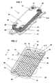
- the accompanying figures show the implementation of the invention with reference to a housing-less plate heat exchanger, which is used for cooling or for controlling the temperature of the transmission oil by means of the cooling liquid of the drive motor in a motor vehicle, the representation is limited to the plate heat exchanger itself.
- the heat exchanger plates 1a, 1b have four openings 21 - 24 in the plate heat exchanger four channels 25 - 28 form, which serve to feed or the discharge of the oil and the coolant.
- the elements of the plate heat exchanger are made of aluminum sheet having a convenient solder coating. From aluminum sheet metal sheet thickness of about 0.3 mm, the heat exchanger plates 1a, 1b are manufactured by means of conventional sheet metal forming.
- the heat exchanger plates 1a, 1b are formed trough-shaped, which is expressed by the peripheral raised edge 10 .
- the plate heat exchanger is closed at the top by a cover plate 30 and at the bottom by a base plate 40 .
- the connections for the two media are provided in the base plate 40 .
- This base plate 40 also serves to secure the plate heat exchanger by means of the bores 41 to another body.
- the knobs 42 in the base plate 40 are used to position the stacked heat exchanger plates 1a, 1b on the base plate 40.
- Shown is a cover plate 30 with cut corners 31, which should allow only a look in the four channels 25-28 - usually the cover plate 30th closed.
- the connections for both media involved in the heat exchange may also be through the cover plate 30, or other arrangements of the connections known in the art may be provided.
- FIGS. 2 and 5 show one of the heat exchanger plates 1a.
- the other heat exchanger plate 1b is shown in FIG.
- Both heat exchanger plates 1a, b show the four openings 21 to 24 forming an annular 50.
- the two types of heat exchanger plates 1a, 1b differ in their grooves 5 third in the floor plate of particular importance is the heat exchanger plate 1a.
- This has first formations 5a , and second formations 5b , which protrude in the opposite direction from the plane of the plate 4 .
- approximately square or rectangular second formations 5b protrude upwards out of the plane of the plate 4
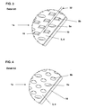
- approximately circular first formations 5a can be seen, which protrude downwards out of the plane of the plate 4 or out of the plate bottom 3. Since Fig.
- FIG. 5 shows a heat exchanger plate 1a of the same kind, but seen from the bottom, there is the direction of the formations 5a, 5b corresponding opposite to the described Fig. 2. This also applies to Fig. 6, only the cutout B from Fig. 5 shows enlarged.
- the rectangular formations 5b have a gradation 15, which can be clearly seen from the enlarged view in FIG. 11.
- the gradation 15 increases the rigidity, it increases the area, and thus contributes to the increased heat exchange efficiency.
- FIGS. 7, 8 and 11 further show, the formation 5b narrows the flow channel 2a .
- the shape of the individual formations 5a , 5b and also that of the formations 5c on the other heat exchanger plates 1b, is in and of itself free and will be selected appropriately by the person skilled in the art.
- FIG. 4 an embodiment is shown in which all the first and second formations 5a , 5b are circular.
- the formations 5c on the heat exchanger plates 1b all point in one direction and, with reference to FIGS. 7 and 8, downwards.
- the height H of the formations 5c is greater than the height h of the formations 5a and 5b.
- the heights H, h determine the distance between the plate bottoms 3 and the height of the flow channels 2a and 2b, which is why in the embodiments shown, the height of the flow channels 2a for the oil is greater than the height of the flow channels 2b for the cooling liquid.
- the height h of the formations 5a and 5b is identical, but this is not absolutely necessary.
- the height h of the formations 5b was provided identically to the height H of the formations 5c , so that the formations 5b also abut the heat exchanger plate 1b and are connected.
- the positioning of the individual formations 5a , 5b in the exemplary embodiment shown is, with reference to FIG.
- rows 11, 12 alternate, viewed in the longitudinal direction 13 of the plate 1a .
- rows 11 formed only of square shapes 5b , and other rows 12 in which a circular shape 5a and a square shape 5b are alternately provided.
- the rows 11, 12 are arranged mirror-inverted to the center 14 of the heat exchanger plate 1a . If necessary, a different order and arrangement of the formations 5a and 5b can be selected. The optimization of the arrangement takes place after the desired minimum pressure loss with simultaneously high heat exchange efficiency.
- the shape of the formations 5a , 5b and 5c can be chosen quite differently, round or oval, square or rectangular, with or without gradation 15 or with more than one gradation 15. Even elongated arcuate formations are possible.
- the circular formations 5a are those which are connected to the adjacent heat exchanger plate 1b of the other type. Set accordingly in the said area 45 between the openings 21 to 24, a particularly high internal pressure stability.
- the formations 5a are connected to the plate bottom 3 of the heat exchanger plates 1b . Since the present application does not exclude such embodiments in which both types of heat exchanger plates 1a, 1b have two types of formations 5 , the formations 5a could also be connected to formations in the plate bottom 3 of the heat exchanger plate 1b .
- the described two types of trough-shaped heat exchanger plates 1a, 1b are alternately stacked one inside the other, so that the flow channels 2a for the oil and 2b for the cooling liquid between the heat exchanger plates 1a and 1b can be seen in FIGS.
- the flow channels 2a are hydraulically connected to the one inlet channel 21 and the one outlet channel 24 and the flow channels 2b corresponding to the other inlet channel 22 and the other outlet channel 23rd
- FIGS. 9, 10 and 11 represent possible directions of flow of the two Media dar.
- the dashed arrows indicate the coolant and the other the oil.
- FIG. 9 shows a horizontal section C - C through part of an oil flow channel 2a of a next embodiment, in which another arrangement of the formations 5a , 5b , 5c has been provided. It is a greatly enlarged representation.
- the cut was made to pass through the protrusions 5c on the heat exchanger plate 1b .
- the section passes through the formations 5b of the heat exchanger plate 1a .
- the formations 5 a on the heat exchanger plate 1 a appear uncut and form a circular ring or ellipse.
- turbulence 29 b results for the oil flowing through.
- the distances 32 should be chosen as small as possible so that the oil is subject to the most efficient heat exchange with the cooling liquid. As can be seen from Fig. 2, the distance 32 can also be almost completely eliminated, so that there is an effective turbulence 29b of the oil.
- FIG. 12 the view from above of a heat exchanger plate 1 b of the other type is shown. Clearly visible is the regular arrangement of the formations 5c, which was down, out of the plate plane 4 of the heat exchanger plate 1b , made. The arrangement of the formations 5a, 5b and 5c of both heat exchanger plates 1a and 1b must be coordinated with each other in order to ensure optimum functioning of the heat exchanger.
- both types of heat exchanger plates 1a, b have a partial deformation 50 and an oppositely directed annular deformation 51 at the openings 21 and 24 .
- Such annular deformations 51 are also located at the other openings 22 and 23.
- the partial deformations 50 serve to effect a flow deflection in the oil-side flow channels 2a into the corners of the plate exchanger to involve the entire surface of the heat exchanger plates in the heat exchange.
Landscapes
- Engineering & Computer Science (AREA)
- Physics & Mathematics (AREA)
- Thermal Sciences (AREA)
- Mechanical Engineering (AREA)
- General Engineering & Computer Science (AREA)
- Heat-Exchange Devices With Radiators And Conduit Assemblies (AREA)
Abstract
Plattenwärmetauscher, bestehend aus wenigstens zwei Arten von Wärmetauscherplatten (1a, 1b), die gestapelt sind, um zwischen sich Strömungskanäle (2a bzw. 2b) zu bilden, wobei die Böden (3) beider Arten Wärmetauscherplatten (1a, 1b) aus der Plattenebene (4) herausragende Ausformungen (5) aufweisen, die sich an der benachbarten Wärmetauscherplatte abstützen und damit verbunden, vorzugsweise verlötet sind.
Die Aufgabe der Erfindung besteht darin, den Plattenwärmetauscher hinsichtlich Festigkeit und Wärmetauscheffizienz an einen vorgegebenen Einsatzfall anzupassen, ohne Inneneinsätze in den Strömungskanälen vorsehen zu müssen, wobei sowohl hinsichtlich der Innendruckstabilität aus auch hinsichtlich der Wärmetauscheffizienz gute Ergebnisse erreicht werden sollen.
Die erfindungsgemäße Lösung ergibt sich dadurch, dass wenigstens die eine Art von Wärmetauscherplatten (1a) zwei Typen von Ausformungen (5a, 5b) aufweist, die in entgegengesetzter Richtung aus der Plattenebene (4) herausragen, wobei der erste Typ von Ausformungen (5a) mit der benachbarten Wärmetauscherplatte (1b) der anderen Art verbunden ist und der zweite Typ von Ausformungen (5b) den Strömungskanal (2a) verengt, indem er in den Raum (16) zwischen wenigstens zwei Ausformungen (5c) an der anderen Art Wärmetauscherplatten (1b) hineinragt.
Description
- Die Erfindung betrifft einen Plattenwärmetauscher, bestehend aus wenigstens zwei Arten von Wärmetauscherplatten, die gestapelt sind, um zwischen sich Strömungskanäle zu bilden, wobei die Böden der Wärmetauscherplatten aus der Plattenebene herausragende Ausformungen aufweisen, die sich an der benachbarten Wärmetauscherplatte abstützen und die damit verbunden, vorzugsweise verlötet sind.
Solche Plattenwärmetauscher sind beispielsweise aus der Fig. 8 des EP 742 418 B1 bekannt, und sie sind dort als Ölkühler vorgesehen. Ferner sind sie aus zahlreichen anderen Veröffentlichungen auch für andere Anwendungsfälle bekannt, von denen DE 100 34 343C2, DE 201 19 565 U1 und US 4 781 248 hier genannt werden.
Bei dem im Oberbegriff beschriebenen Plattenwärmetauscher sind keine Inneneinsätze in den Strömungskanälen vorgesehen, weil diese sehr oft Ursache dafür sind, dass Rückstände in den Strömungskanälen verbleiben, die sehr schwer zu entfernen sind. Die Rückstände sind beispielsweise feine metallische Späne, die bei der Fertigung der Inneneinsätze entstehen. Wenn diese Rückstände beispielsweise in den Ölkreislauf gelangen, kann das zum Ausfall des Systems führen. Bezüglich der Wärmetauscheffizienz sind mit Inneneinsätzen jedoch oft bessere Ergebnisse zu erzielen als mit Ausformungen der Plattenböden. Auch was die Festigkeit des Plattenwärmetauschers, insbesondere seine Widerstandsfähigkeit gegenüber hohen Innendrücken, betrifft, haben die Inneneinsätze oft Vorteile gegenüber den erwähnten Ausformungen, da sie relativ großflächig mit den gegenüberliegenden Plattenböden der Wärmetauscherplatten metallisch verbunden sind. - Die Aufgabe der Erfindung besteht darin, den Plattenwärmetauscher hinsichtlich Festigkeit und Wärmetauscheffizienz an einen vorgegebenen Einsatzfall anzupassen, ohne Inneneinsätze in den Strömungskanälen vorsehen zu müssen, wobei sowohl hinsichtlich der Innendruckstabilität aus auch hinsichtlich der Wärmetauscheffizienz gute Ergebnisse erreicht werden sollen.
Die erfindungsgemäße Lösung ergibt sich bei dem Plattenwärmetauscher gemäß dem Oberbegriff des Anspruchs 1 aus dessen Kennzeichen.
Die eine Art von Wärmetauscherplatten weist zwei Typen von Ausformungen auf, die in entgegengesetzter Richtung aus der Plattenebene herausragen. Der erste Typ von Ausformungen ist mit der benachbarten Wärmetauscherplatte der anderen Art verbunden. Der zweite Typ von Ausformungen verengt den Strömungskanal, indem er in den Raum zwischen wenigstens zwei Ausformungen der anderen Art Wärmetauscherplatten hinein ragt. In einem Ausführungsbeispiel sind mehrere, beispielsweise drei oder vier, den Raum bildende Ausformungen vorgesehen. In diesen Raum hinein ragt wenigstens eine Ausformung des erwähnten zweiten Typs und verengt dadurch den Strömungskanal.
Durch entsprechende Platzierung und Gestaltung der beiden Typen von Ausformungen wird der Plattenwärmetauscher hinsichtlich gewünschter Wärmetauscheffizienz und hinsichtlich der erforderlichen Innendruckstabilität auf den vorhandenen Anwendungsfall angepasst. Die Innendruckstabilität wird durch die verbundenen Ausformungen erreicht und die verbesserte Wärmetauscheffizienz wird durch den zweiten Typ der Ausformungen erreicht. Der Ausformungen zweiten Typs vergrößern die wärmetauschenden Flächen und sie erhöhen die Strömungsgeschwindigkeit des Mediums durch Verengung des Kanals, wodurch die erwähnte Verbesserung der Wärmetauscheffizienz erreicht wird. Die Vergrößerung der Fläche, die zum Wärmeaustausch zur Verfügung steht, wird hier im anderen Strömungskanal durch den zweiten Typ von Ausformung erreicht.
Beide Typen von Ausformungen können mit identischer Gestalt ausgebildet sind.
Sie können jedoch auch unterschiedliche Gestalt aufweisen.
Die Anzahl und Anordnung beider Typen von Ausformungen ist so vorgesehen, dass der Plattenwärmetauscher hinsichtlich Festigkeit und Wärmetauscheffizienz optimierbar ist.
Beide Arten Wärmetauscherplatten sind wannenförmig ausgebildet, ineinander gesetzt und auch am abragenden Rand miteinander verbunden.
Bei einer alternativen Ausführung liegt der eine Typ von Ausformungen an der einen Art von Wärmetauscherplatten an der Plattenebene der anderen Art Wärmetauscherplatte an und ist damit verbunden. - Die Höhe der zwei Typen von Ausformungen in der einen Art Wärmetauscherplatten ist vorzugsweise identisch, ohne dass Ausführungen ausgeschlossen sind, in denen die Höhe der zwei Typen von Ausformungen unterschiedlich ist.
Die Höhe der Ausformungen in der anderen Art Wärmetauscherplatten ist vorzugsweise größer als die Höhe der Ausformungen in der einen Art Wärmetauscherplatten. Je nach Wahl der Höhen der verschiedenen Ausformungen ergeben sich unterschiedlich hohe Strömungskanäle für die beteiligten Medien. Die Form und Höhe der verschiedenen Ausformungen ist der gewünschten Wärmeaustauscheffizienz anzupassen. - Die beiden Arten Wärmetauscherplatten unterscheiden sich also dadurch voneinander, dass ihre Ausformungen unterschiedlich sind. Die eine Art weist Ausformungen auf, die nur in einer Richtung aus der Plattenebene herausragen, während die andere Art die erwähnten zwei Typen von Ausformungen hat, wobei der erste Typ in die eine Richtung aus der Plattenebene herausragt und der zweite Typ in die entgegengesetzte Richtung aus der Plattenebene herausragt.
Im Stapel aus Wärmetauscherplatten wechseln sich Wärmetauscherplatten der einen Art mit Wärmetauscherplatten der anderen Art ab, d. h., auf eine Wärmetauscherplatte der einen Art folgt eine Wärmetauscherplatte der anderen Art.
Es handelt sich vorzugsweise um einen gehäuselosen Plattenwärmetauscher, mit wenigstens vier Öffnungen in allen Wärmetauscherplatten. Diese Öffnungen bilden im Stapel vier vertikale Kanäle, von denen zwei der Zu - bzw. Abführung von Öl und die anderen zwei der Zu - bzw. Abführung einer Kühlflüssigkeit dienen. - Dadurch dass man bei dem erfindungsgemäßen Wärmetauscher darauf verzichtet, zusätzliche Einlege/Turbulenzbleche zu verwenden, lässt sich der Wärmetauscher günstiger in einem automatisierten Prozess herstellen. Es müssen lediglich zwei verschiedene Arten von Wärmetauscherplatten übereinander gestapelt werden. Auf diese Weise können die Herstellungskosten gesenkt werden.
- Weitere Merkmale ergeben sich aus den abhängigen Patentansprüchen sowie aus der nachfolgenden Beschreibung von Ausführungsbeispielen unter Bezugnahme auf die beiliegenden Zeichnungen.
- Die Figuren zeigen Folgendes:
- Fig. 1 Perspektivansicht des Plattenwärmetauschers;
- Fig. 2 eine Wärmetauscherplatte der einen Art, von oben gesehen;
- Fig. 3 Einzelheit A1 aus Fig. 2
- Fig. 4 Einzelheit A2 aus Fig. 2;
- Fig. 5 die Wärmetauscherplatte der einen Art, von unten gesehen;
- Fig. 6 Einzelheit B aus Fig. 5;
- Fig. 7 Schnitt durch den Plattenwärmetauscher;
- Fig. 8 Schnitt durch eine andere Stelle des Plattenwärmetauschers;
- Fig. 9 Schnitt C-C aus Fig. 7;
- Fig. 10 Ausschnitt aus dem Plattenwärmetauscher;
- Fig. 11 Alternative zu Fig. 10;
- Fig. 12 die Wärmetauscherplatte der anderen Art, von oben gesehen,
- Fig. 13 Ausschnitt aus Fig. 1.
- Die beigefügten Abbildungen zeigen die Umsetzung der Erfindung anhand eines gehäuselosen Plattenwärmetauschers, der zur Kühlung bzw. zur Temperierung des Getriebeöls mittels der Kühlflüssigkeit des Antriebsmotors in einem Kraftfahrzeug eingesetzt wird, wobei die Darstellung auf den Plattenwärmetauscher selbst beschränkt ist. Die Wärmetauscherplatten 1a, 1b besitzen vier Öffnungen 21 - 24, die im Plattenwärmetauscher vier Kanäle 25 - 28 bilden, die der Zuführung bzw. der Abführung des Öls und der Kühlflüssigkeit dienen. Die Elemente des Plattenwärmetauschers werden aus Aluminiumblech hergestellt, das eine zweckmäßige Lotbeschichtung aufweist. Aus Aluminiumblech der Blechdicke von etwa 0,3 mm werden die Wärmetauscherplatten 1a, 1b mittels geläufiger Blechumformverfahren gefertigt. Die Wärmetauscherplatten 1a, 1b sind wannenförmig ausgebildet, was durch den umlaufenden hochgestellten Rand 10 zum Ausdruck kommt. Der Plattenwärmetauscher wird oben von einer Deckplatte 30 und unten von einer Grundplatte 40 abgeschlossen. Die Anschlüsse für die beiden Medien sind in der Grundplatte 40 vorgesehen. Diese Grundplatte 40 dient gleichzeitig dazu, den Plattenwärmetauscher mittels der Bohrungen 41 an einem anderen Körper zu befestigen. Die Noppen 42 in der Grundplatte 40 dienen der Positionierung der gestapelten Wärmetauscherplatten 1a, 1b auf der Grundplatte 40. Dargestellt ist eine Deckplatte 30 mit ausgeschnittenen Ecken 31, die nur einen Blick in die vier Kanäle 25-28 ermöglichen sollen - normalerweise ist die Deckplatte 30 geschlossen. Je nach den Anforderungen können die Anschlüsse für beide Medien, die am Wärmeaustausch beteiligt sind, auch durch die Deckplatte 30 erfolgen, oder es können andere aus dem Stand der Technik bekannte Anordnungen der Anschlüsse vorgesehen werden.
- Die Fig. 2 und 5 zeigen eine der Wärmetauscherplatten 1a. Die andere Wärmetauscherplatte 1b ist in der Fig. 12 dargestellt. Beide Wärmetauscherplatten 1a, b zeigen an den vier Öffnungen 21 - 24 eine ringförmige Umformung 50. Die beiden Arten von Wärmetauscherplatten 1a, 1b unterscheiden sich hinsichtlich ihrer Ausformungen 5 im Plattenboden 3. Von besonderer Bedeutung ist hierbei die Wärmetauscherplatte 1a. Diese besitzt erste Ausformungen 5a, und zweite Ausformungen 5b, die in entgegengesetzter Richtung aus der Plattenebene 4 herausragen. In der Fig. 2 ragen etwa quadratische oder rechteckförmige zweite Ausformungen 5b nach oben aus der Plattenebene 4 heraus, und es sind etwa kreisförmige erste Ausformungen 5a zu erkennen, die nach unten aus der Plattenebene 4 bzw. aus dem Plattenboden 3 herausragen. Da die Fig. 5 eine Wärmetauscherplatte 1a derselben Art zeigt, allerdings von der Unterseite gesehen, ist dort die Richtung der Ausformungen 5a, 5b entsprechend entgegengesetzt zur beschriebenen Fig. 2. Dies gilt auch für die Fig. 6, die lediglich den Ausschnitt B aus Fig. 5 vergrößert darstellt. Die rechteckförmigen Ausformungen 5b besitzen eine Abstufung 15, was aus der vergrößerten Darstellung in der Fig. 11 gut zu erkennen ist. Die Abstufung 15 erhöht die Steifigkeit, sie vergrößert die Fläche, und sie trägt somit zur erhöhten Wärmetauscheffizienz bei. Wie die Figuren 7, 8 und 11 weiter zeigen, engt die Ausformung 5b den Strömungskanal 2a ein. Die Gestalt der einzelnen Ausformungen 5a, 5b und auch diejenige der Ausformungen 5c an den anderen Wärmetauscherplatten 1b, ist an und für sich freigestellt und wird vom Fachmann zweckentsprechend ausgewählt werden. In der Fig. 4 ist beispielsweise eine Ausführung gezeigt, bei der alle ersten und zweiten Ausformungen 5a, 5b kreisförmig sind. Die Ausformungen 5c an den Wärmetauscherplatten 1 b weisen alle in eine Richtung und zwar, mit Blick auf die Fig. 7 und 8, nach unten. Die Höhe H der Ausformungen 5c ist größer als die Höhe h der Ausformungen 5a bzw. 5b. Die Höhen H, h bestimmen den Abstand zwischen den Plattenböden 3 bzw. die Höhe der Strömungskanäle 2a bzw. 2b, weshalb in den gezeigten Ausführungsbeispielen die Höhe der Strömungskanäle 2a für das Öl größer ist als die Höhe der Strömungskanäle 2b für die Kühlflüssigkeit. In den gezeigten Ausführungsbeispielen ist die Höhe h der Ausformungen 5a und 5b identisch, dies ist jedoch nicht unbedingt erforderlich. In einem nicht gezeigten Ausführungsbeispiel wurde die Höhe h der Ausformungen 5b identisch mit der Höhe H der Ausformungen 5c vorgesehen, sodass die Ausformungen 5b darüber hinaus ebenfalls an der Wärmetauscherplatte 1b anliegen und verbunden sind.
Die Positionierung der einzelnen Ausformungen 5a, 5b im gezeigten Ausführungsbeispiel ist mit Blick auf die Fig. 2 so, dass sich - in Längsrichtung 13 der Platte 1a gesehen - unterschiedliche Reihen 11, 12 abwechseln. Es sind Reihen 11, die nur aus quadratischen Ausformungen 5b gebildet sind, vorhanden und andere Reihen 12, in denen abwechselnd eine kreisförmige Ausformung 5a und eine quadratische Ausformung 5b vorgesehen ist. Die Reihen 11, 12 sind zur Mitte 14 der Wärmetauscherplatte 1a hin spiegelbildlich angeordnet. Bei Bedarf kann auch eine andere Reihenfolge und Anordnung der Ausformungen 5a und 5b gewählt werden. Die Optimierung der Anordnung erfolgt nach gewünschtem minimalem Druckverlust mit gleichzeitig hoher Wärmetauscheffizienz. Die Form der Ausformungen 5a, 5b und 5c kann recht unterschiedlich gewählt werden, rund oder oval, quadratisch oder rechteckig, mit oder ohne Abstufung 15 oder mit mehr als einer Abstufung 15. Auch lang gestreckte bogenförmige Ausformungen sind möglich.
Im Plattenboden 3 im Gebiet 45 zwischen den Öffnungen 21, 22 bzw. 23, 24 ist auffällig, dass dort eine Vielzahl von kreisförmigen Ausformungen 5a konzentriert ist. Bei den kreisförmigen Ausformungen 5a handelt es sich um diejenigen, die mit der benachbarten Wärmetauscherplatte 1b der anderen Art verbunden sind. Sie stellen demzufolge in dem genannten Gebiet 45 zwischen den Öffnungen 21 - 24 eine besonders hohe Innendruckstabilität zur Verfügung. In den gezeigten Ausführungsbeispielen sind die Ausformungen 5a mit dem Plattenboden 3 der Wärmetauscherplatten 1b verbunden. Da die vorliegende Anmeldung auch solche Ausführungen nicht ausschließt, in denen beide Arten Wärmetauscherplatten 1a, 1b zwei Typen von Ausformungen 5 aufweisen, könnten die Ausformungen 5a auch mit Ausformungen im Plattenboden 3 der Wärmetauscherplatte 1b verbunden sein. (nicht gezeigt)
Die beschriebenen zwei Arten wannenförmiger Wärmetauscherplatten 1a, 1b werden im Wechsel ineinander gestapelt, sodass sich die in den Fig. 7 und 8 zu erkennenden Strömungskanäle 2a für das Öl und 2b für die Kühlflüssigkeit zwischen den Wärmetauscherplatten 1a und 1b ergeben. Die Strömungskanäle 2a sind hydraulisch mit dem einen Eintrittskanal 21 und dem einen Austrittskanal 24 verbunden und die Strömungskanäle 2b entsprechend mit dem anderen Eintrittskanal 22 und dem anderen Austrittskanal 23. - Aus den genannten Abbildungen und aus den Fig. 10 und 11 ist zu sehen, dass die Ausformungen 5b jeweils in einen Raum 16 zwischen zwei Ausformungen 5c ragen und dort Turbulenzen 29b erzeugen Die Pfeile in Fig. 9, 10 und 11 stellen mögliche Strömungsrichtungen der beiden Medien dar. Die gestrichelten Pfeile zeigen die Kühlflüssigkeit an und die anderen das Öl.
- Die Fig. 9 zeigt einen Horizontalschnitt C - C durch einen Teil eines Öl - Strömungskanals 2a eines nächsten Ausführungsbeispiels, in dem eine andere Anordnung der Ausformungen 5a, 5b, 5c vorgesehen wurde. Es handelt sich um eine stark vergrößerte Darstellung. Der Schnitt wurde so gelegt, dass er durch die Ausformungen 5c an der Wärmetauscherplatte 1b hindurchgeht. Außerdem geht der Schnitt durch die Ausformungen 5b der Wärmetauscherplatte 1a. Die Ausformungen 5a an der Wärmetauscherplatte 1 a erscheinen ungeschnitten und stellen sich als Kreisring oder Ellipse dar. In den Bereichen um die Ausformung 5b ergeben sich für das durchströmende Öl Turbulenzen 29b. Zwischen den Ausformungen 5c und 5b kann das Öl geradlinig strömen 29a. Die Abstände 32 sollten möglichst klein gewählt werden, damit das Öl einem möglichst effizienten Wärmeaustausch mit der Kühlflüssigkeit unterliegt. Wie aus Fig. 2 zu erkennen ist, kann der Abstand 32 auch fast ganz wegfallen, sodass es zu einer effektiven Verwirbelung 29b des Öls kommt.
- In Fig. 12 ist die Ansicht von oben auf eine Wärmetauscherplatte 1b der anderen Art dargestellt. Deutlich zu sehen ist die regelmäßige Anordnung der Ausformungen 5c, die nach unten, aus der Plattenebene 4 der Wärmetauscherplatte 1b herausweisend, vorgenommen wurde. Die Anordnung der Ausformungen 5a, 5b und 5c beider Wärmetauscherplatten 1a und 1b muss aufeinander abgestimmt sein, um ein optimales Funktionieren des Wärmetauschers zu gewährleisten.
- Aus den Fig. 2 und 12 ist zu erkennen, dass beide Arten von Wärmetauscherplatten 1a,b an den Öffnungen 21 und 24 eine partielle Umformung 50 und eine entgegengesetzt gerichtete ringförmige Umformung 51 besitzen. Solche ringförmigen Umformungen 51 befinden sich auch an den anderen Öffnungen 22 und 23. Die partiellen Umformungen 50 dienen dazu, in den ölseitigen Strömungskanälen 2a eine Strömungsumlenkung in die Ecken des Plattenwämtauschers hinein zu bewirken, um die gesamte Fläche der Wärmetauscherplatten am Wärmeaustausch zu beteiligen.
- Diese Art der Umformung der Wärmetauscherplatte am Rand der Öffnungen wurde bereits in der noch nicht veröffentlichten Anmeldung mit dem Aktenzeichen DE 103 48 803.0, die der Anmelderin gehört, beschrieben. Im Unterschied zu der genannten Anmeldung wurden hier lediglich zwei der vier Öffnungen mit den partiellen Umformungen 50 versehen. Weitere Ausgestaltungsmöglichkeiten der partiellen Umformung 50 finden sich in der DE 103 48 803.0.
Claims (14)
- Plattenwärmetauscher, bestehend aus wenigstens zwei Arten von Wärmetauscherplatten (1a, 1b), die gestapelt sind, um zwischen sich Strömungskanäle (2a bzw. 2b) zu bilden, wobei die Böden (3) beider Arten Wärmetauscherplatten (1a, 1b) aus der Plattenebene (4) herausragende Ausformungen (5) aufweisen, die sich an der benachbarten Wärmetauscherplatte abstützen und damit verbunden, vorzugsweise verlötet sind,
dadurch gekennzeichnet, dass wenigstens die eine Art von Wärmetauscherplatten (1a) zwei Typen von Ausformungen (5a, 5b) aufweist, die in entgegengesetzter Richtung aus der Plattenebene (4) herausragen, wobei der erste Typ von Ausformungen (5a) mit der benachbarten Wärmetauscherplatte (1b) der anderen Art verbunden ist und der zweite Typ von Ausformungen (5b) den Strömungskanal (2a) verengt, indem er in den Raum (16) zwischen wenigstens zwei Ausformungen (5c) an der anderen Art Wärmetauscherplatten (1b) hineinragt. - Plattenwärmetauscher nach Anspruch 1, dadurch gekennzeichnet, dass beide Typen von Ausformungen (5a, 5b) mit identischer Gestalt ausgebildet sind.
- Plattenwärmetauscher nach Anspruch 1, dadurch gekennzeichnet, dass die beiden Typen von Ausformungen (5a, 5b) unterschiedlicher Gestalt sind.
- Plattenwärmetauscher nach einem der Ansprüche 1 - 3, dadurch gekennzeichnet, dass die Anzahl, die Gestalt und die Anordnung beider Typen von Ausformungen (5a, 5b) so vorgesehen ist, dass der Plattenwärmetauscher hinsichtlich Festigkeit und Wärmetauscheffizienz optimiert ist.
- Plattenwärmetauscher nach einem der vorstehenden Ansprüche, dadurch gekennzeichnet, dass beide Arten Wärmetauscherplatten (1a, 1b) wannenförmig ausgebildet, ineinander gesetzt und auch am abragenden Rand (10) miteinander verbunden sind.
- Plattenwärmetauscher nach einem der vorstehenden Ansprüche, dadurch gekennzeichnet, dass der zweite Typ von Ausformungen (5b) an der einen Art Wärmetauscherplatten (1a) nicht an der anderen Art Wärmetauscherplatte (1b) anliegt und verbunden ist.
- Plattenwärmetauscher nach einem der vorstehenden Ansprüche 1-5, dadurch gekennzeichnet, dass der zweite Typ von Ausformungen (5b) der einen Art von Wärmetauscherplatten (1a) an der Plattenebene (4) der anderen Art Wärmetauscherplatte (1b) anliegt und verbunden ist.
- Plattenwärmetauscher nach einem der vorstehenden Ansprüche, dadurch gekennzeichnet, dass der erste Typ von Ausformungen (5a) an der Plattenebene (4) der anderen Art Wärmetauscherplatte (1b) anliegt und verbunden ist.
- Plattenwärmetauscher nach einem der vorstehenden Ansprüche, dadurch gekennzeichnet, dass die Höhe (h) der zwei Typen von Ausformungen (5a, 5b) in der einen Art Wärmetauscherplatten (1a) identisch ist.
- Plattenwärmetauscher nach einem der vorstehenden Ansprüche 1- 8, dadurch gekennzeichnet, dass die Höhe (h) der zwei Typen von Ausformungen (5a, 5b) in der einen Art Wärmetauscherplatten (1a) unterschiedlich ist.
- Plattenwärmetauscher nach einem der vorstehenden Ansprüche, dadurch gekennzeichnet, dass die Höhe (H) der Ausformungen (5c) in der anderen Art Wärmetauscherplatten (1b) größer ist als die Höhe (h) der Ausformungen ersten und zweiten Typs (5a, 5b) in der einen Art Wärmetauscherplatten (1a).
- Plattenwärmetauscher nach einem der vorstehenden Ansprüche, dadurch gekennzeichnet, dass alle Wärmetauscherplatten (1a, 1b) wenigstens vier Öffnungen (21-24) aufweisen, die im Stapel mittels einer ringförmigen Umformung (51) vier vertikale Kanäle (25 - 28) bilden, von denen zwei der Zu - bzw. Abführung von Öl und die anderen zwei der Zu - bzw. Abführung einer Kühlflüssigkeit dienen.
- Plattenwärmetauscher nach einem der vorstehenden Ansprüche, dadurch gekennzeichnet, dass bei allen Wärmetauscherplatten (1a, 1b) sämtliche oder lediglich zwei der vier Öffnungen (21-24), die zum Öl und/oder zur Kühlflüssigkeit gehören, eine partielle Umformung (50) an ihrem Rand aufweisen, die eine Umlenkung des Öls und / oder der Kühlflüssigkeit bewirkt.
- Plattenwärmetauscher nach einem der vorstehenden Ansprüche, dadurch gekennzeichnet, dass diejenigen Strömungskanäle (2a), in denen der erste Typ von Ausformungen (5a) mit der benachbarten Wärmertauscherplatte (1b) verbunden ist, für die Kühlflüssigkeit vorgesehen sind und die anderen Strömungskanäle (2b), in die der zweite Typ von Ausformungen (5b) hineinragt, für das Öl gedacht sind.
Applications Claiming Priority (1)
| Application Number | Priority Date | Filing Date | Title |
|---|---|---|---|
| DE200410032353 DE102004032353A1 (de) | 2004-07-03 | 2004-07-03 | Plattenwärmetauscher |
Publications (1)
| Publication Number | Publication Date |
|---|---|
| EP1612499A2 true EP1612499A2 (de) | 2006-01-04 |
Family
ID=35045059
Family Applications (1)
| Application Number | Title | Priority Date | Filing Date |
|---|---|---|---|
| EP20050012472 Withdrawn EP1612499A2 (de) | 2004-07-03 | 2005-06-10 | Plattenwärmetauscher |
Country Status (2)
| Country | Link |
|---|---|
| EP (1) | EP1612499A2 (de) |
| DE (1) | DE102004032353A1 (de) |
Cited By (7)
| Publication number | Priority date | Publication date | Assignee | Title |
|---|---|---|---|---|
| WO2008071356A1 (en) * | 2006-12-11 | 2008-06-19 | Invensys Apv A/S | Heat exchanger plate |
| CN101865626A (zh) * | 2010-06-21 | 2010-10-20 | 四川宜宾江源化工机械制造有限责任公司 | 一种用于板式换热器的换热板 |
| DE102012022046A1 (de) | 2012-11-09 | 2014-05-15 | Modine Manufacturing Co. | Wärmetauscher |
| DE102018007010A1 (de) * | 2018-09-05 | 2020-03-05 | Modine Manufacturing Co. | Fluidströmungskanal mit Effizienz-steigernden Umformungen |
| CN115355743A (zh) * | 2022-09-28 | 2022-11-18 | 江阴市亚龙换热设备有限公司 | 高耐压高换热率钎焊式换热器 |
| CN115468443A (zh) * | 2022-09-28 | 2022-12-13 | 江阴市亚龙换热设备有限公司 | 高度均流型钎焊式换热器 |
| WO2025261497A1 (zh) * | 2024-06-20 | 2025-12-26 | 绍兴三花汽车热管理科技有限公司 | 换热器 |
Families Citing this family (6)
| Publication number | Priority date | Publication date | Assignee | Title |
|---|---|---|---|---|
| US7992628B2 (en) | 2006-05-09 | 2011-08-09 | Modine Manufacturing Company | Multi-passing liquid cooled charge air cooler with coolant bypass ports for improved flow distribution |
| AT508058B1 (de) | 2009-03-05 | 2011-01-15 | Mahle Int Gmbh | Plattenwärmetauscher |
| CN111238266A (zh) * | 2014-01-29 | 2020-06-05 | 丹佛斯微通道换热器(嘉兴)有限公司 | 热交换板和具有该热交换板的板式热交换器 |
| CA2959006A1 (en) | 2014-09-09 | 2016-03-17 | Bombardier Recreational Product Inc. | Snowmobile heat exchanger assembly |
| CA2959261A1 (en) | 2014-09-09 | 2016-03-17 | Bombardier Recreational Products Inc. | Heat exchanger for a snowmobile engine air intake |
| DE102016002621A1 (de) * | 2016-03-07 | 2017-09-07 | Modine Manufacturing Company | Multifunktionelle Grundplatte eines Wärmeübertragers |
Family Cites Families (5)
| Publication number | Priority date | Publication date | Assignee | Title |
|---|---|---|---|---|
| DE3622316C1 (de) * | 1986-07-03 | 1988-01-28 | Schmidt W Gmbh Co Kg | Plattenwaermeaustauscher |
| DE3726072A1 (de) * | 1987-08-06 | 1989-02-16 | Thyssen Edelstahlwerke Ag | Loet-verfahren |
| JPH0942865A (ja) * | 1995-07-28 | 1997-02-14 | Honda Motor Co Ltd | 熱交換器 |
| AUPN697995A0 (en) * | 1995-12-04 | 1996-01-04 | Urch, John Francis | Metal heat exchanger |
| SE520703C2 (sv) * | 2001-12-18 | 2003-08-12 | Alfa Laval Corp Ab | Värmeväxlarplatta med korrugerat stödområde, plattpaket samt plattvärmeväxlare |
-
2004
- 2004-07-03 DE DE200410032353 patent/DE102004032353A1/de not_active Withdrawn
-
2005
- 2005-06-10 EP EP20050012472 patent/EP1612499A2/de not_active Withdrawn
Cited By (7)
| Publication number | Priority date | Publication date | Assignee | Title |
|---|---|---|---|---|
| WO2008071356A1 (en) * | 2006-12-11 | 2008-06-19 | Invensys Apv A/S | Heat exchanger plate |
| CN101865626A (zh) * | 2010-06-21 | 2010-10-20 | 四川宜宾江源化工机械制造有限责任公司 | 一种用于板式换热器的换热板 |
| DE102012022046A1 (de) | 2012-11-09 | 2014-05-15 | Modine Manufacturing Co. | Wärmetauscher |
| DE102018007010A1 (de) * | 2018-09-05 | 2020-03-05 | Modine Manufacturing Co. | Fluidströmungskanal mit Effizienz-steigernden Umformungen |
| CN115355743A (zh) * | 2022-09-28 | 2022-11-18 | 江阴市亚龙换热设备有限公司 | 高耐压高换热率钎焊式换热器 |
| CN115468443A (zh) * | 2022-09-28 | 2022-12-13 | 江阴市亚龙换热设备有限公司 | 高度均流型钎焊式换热器 |
| WO2025261497A1 (zh) * | 2024-06-20 | 2025-12-26 | 绍兴三花汽车热管理科技有限公司 | 换热器 |
Also Published As
| Publication number | Publication date |
|---|---|
| DE102004032353A1 (de) | 2006-01-26 |
Similar Documents
| Publication | Publication Date | Title |
|---|---|---|
| DE69422207T2 (de) | Plattenwärmetauscher und entsprechende Platten | |
| EP2045556B1 (de) | Plattenwärmetauscher | |
| DE102006048305B4 (de) | Plattenwärmetauscher | |
| DE60010227T2 (de) | Gehäuseloser wärmetauscher | |
| DE3752324T2 (de) | Kondensator | |
| DE2657308C3 (de) | Querstrom-Wärmetauscher, mit einer Mehrzahl im wesentlichen identischer Platten, welche parallele Strömungswege bilden | |
| EP1273864B1 (de) | Wärmetauscher | |
| DE69907662T2 (de) | Plattenwärmetauscher | |
| DE10118625B4 (de) | Wellenförmige Lamelle mit Versatz für Plattenwärmetauscher | |
| DE69707161T2 (de) | Wärmetauscher | |
| DE102015010310B4 (de) | Gelöteter Wärmetauscher und Herstellungsverfahren | |
| EP1306638B1 (de) | Gehäuseloser Plattenwärmetauscher | |
| DE19802012C2 (de) | Gehäuseloser Plattenwärmetauscher | |
| DE10347181B4 (de) | Wärmetauscher, insbesondere Ölkühler | |
| DE112018004787T5 (de) | Multi-fluid wärmetauscher | |
| DE102004036951A1 (de) | Wärmeübertrager sowie Verfahren zu dessen Herstellung | |
| DE3330385A1 (de) | Aufprall-kuehleinrichtung | |
| DE112018006027T5 (de) | Verbesserte wärmeübertragungsfläche | |
| EP1612499A2 (de) | Plattenwärmetauscher | |
| DE19858652A1 (de) | Plattenwärmeaustauscher | |
| EP1910764B2 (de) | Plattenelement für einen plattenkühler | |
| DE3131737C2 (de) | ||
| DE3023197A1 (de) | Tasche zur leitung eines mediums in einem waermetauscher | |
| DE102015209858B4 (de) | Plattenwärmetauscher | |
| EP0867679A2 (de) | Plattenwärmetauscher, insbesondere Ölkühler |
Legal Events
| Date | Code | Title | Description |
|---|---|---|---|
| PUAI | Public reference made under article 153(3) epc to a published international application that has entered the european phase |
Free format text: ORIGINAL CODE: 0009012 |
|
| AK | Designated contracting states |
Kind code of ref document: A2 Designated state(s): AT BE BG CH CY CZ DE DK EE ES FI FR GB GR HU IE IS IT LI LT LU MC NL PL PT RO SE SI SK TR |
|
| AX | Request for extension of the european patent |
Extension state: AL BA HR LV MK YU |
|
| STAA | Information on the status of an ep patent application or granted ep patent |
Free format text: STATUS: THE APPLICATION HAS BEEN WITHDRAWN |
|
| 18W | Application withdrawn |
Effective date: 20110318 |