EP1612329A1 - Faserverbund Walzenbezug - Google Patents
Faserverbund Walzenbezug Download PDFInfo
- Publication number
- EP1612329A1 EP1612329A1 EP05103508A EP05103508A EP1612329A1 EP 1612329 A1 EP1612329 A1 EP 1612329A1 EP 05103508 A EP05103508 A EP 05103508A EP 05103508 A EP05103508 A EP 05103508A EP 1612329 A1 EP1612329 A1 EP 1612329A1
- Authority
- EP
- European Patent Office
- Prior art keywords
- fiber
- component
- roll cover
- roll
- fiber composite
- Prior art date
- Legal status (The legal status is an assumption and is not a legal conclusion. Google has not performed a legal analysis and makes no representation as to the accuracy of the status listed.)
- Granted
Links
- 239000000835 fiber Substances 0.000 title claims abstract description 173
- 239000011208 reinforced composite material Substances 0.000 title 1
- 239000000945 filler Substances 0.000 claims abstract description 73
- 239000011159 matrix material Substances 0.000 claims abstract description 66
- 239000000203 mixture Substances 0.000 claims abstract description 51
- 238000000034 method Methods 0.000 claims abstract description 42
- 239000000463 material Substances 0.000 claims abstract description 30
- 229920005989 resin Polymers 0.000 claims abstract description 27
- 239000011347 resin Substances 0.000 claims abstract description 27
- 238000009826 distribution Methods 0.000 claims abstract description 19
- 239000002131 composite material Substances 0.000 claims description 34
- 229920000647 polyepoxide Polymers 0.000 claims description 8
- -1 for example Substances 0.000 claims description 7
- OKTJSMMVPCPJKN-UHFFFAOYSA-N Carbon Chemical compound [C] OKTJSMMVPCPJKN-UHFFFAOYSA-N 0.000 claims description 6
- 239000004760 aramid Substances 0.000 claims description 6
- 229920003235 aromatic polyamide Polymers 0.000 claims description 6
- 229910052799 carbon Inorganic materials 0.000 claims description 6
- 239000003822 epoxy resin Substances 0.000 claims description 6
- 239000011521 glass Substances 0.000 claims description 6
- 239000004696 Poly ether ether ketone Substances 0.000 claims description 5
- 239000004734 Polyphenylene sulfide Substances 0.000 claims description 5
- 239000004743 Polypropylene Substances 0.000 claims description 5
- JUPQTSLXMOCDHR-UHFFFAOYSA-N benzene-1,4-diol;bis(4-fluorophenyl)methanone Chemical compound OC1=CC=C(O)C=C1.C1=CC(F)=CC=C1C(=O)C1=CC=C(F)C=C1 JUPQTSLXMOCDHR-UHFFFAOYSA-N 0.000 claims description 5
- 239000003795 chemical substances by application Substances 0.000 claims description 5
- 230000001419 dependent effect Effects 0.000 claims description 5
- 229910052751 metal Inorganic materials 0.000 claims description 5
- 239000002184 metal Substances 0.000 claims description 5
- 229920002530 polyetherether ketone Polymers 0.000 claims description 5
- 229920000069 polyphenylene sulfide Polymers 0.000 claims description 5
- 229920005749 polyurethane resin Polymers 0.000 claims description 5
- 229920001169 thermoplastic Polymers 0.000 claims description 5
- 239000004416 thermosoftening plastic Substances 0.000 claims description 5
- ZOXJGFHDIHLPTG-UHFFFAOYSA-N Boron Chemical compound [B] ZOXJGFHDIHLPTG-UHFFFAOYSA-N 0.000 claims description 3
- 229910052796 boron Inorganic materials 0.000 claims description 3
- 239000004643 cyanate ester Substances 0.000 claims description 3
- 238000002347 injection Methods 0.000 claims description 3
- 239000007924 injection Substances 0.000 claims description 3
- 150000002739 metals Chemical class 0.000 claims description 3
- 229920001568 phenolic resin Polymers 0.000 claims description 3
- 239000005011 phenolic resin Substances 0.000 claims description 3
- 229920000728 polyester Polymers 0.000 claims description 3
- 229920001155 polypropylene Polymers 0.000 claims description 3
- 239000004698 Polyethylene Substances 0.000 claims description 2
- 239000000919 ceramic Substances 0.000 claims description 2
- 150000001913 cyanates Chemical class 0.000 claims description 2
- 229920006258 high performance thermoplastic Polymers 0.000 claims description 2
- 239000012784 inorganic fiber Substances 0.000 claims description 2
- 150000001247 metal acetylides Chemical class 0.000 claims description 2
- 239000004810 polytetrafluoroethylene Substances 0.000 claims description 2
- 229920001343 polytetrafluoroethylene Polymers 0.000 claims description 2
- 229920003225 polyurethane elastomer Polymers 0.000 claims description 2
- 239000012815 thermoplastic material Substances 0.000 claims description 2
- 150000002118 epoxides Chemical class 0.000 claims 1
- 239000004634 thermosetting polymer Substances 0.000 claims 1
- 238000004519 manufacturing process Methods 0.000 abstract description 8
- 239000004848 polyfunctional curative Substances 0.000 abstract description 8
- 238000002156 mixing Methods 0.000 abstract description 6
- 239000002245 particle Substances 0.000 abstract description 3
- 150000001875 compounds Chemical class 0.000 abstract 4
- 230000007423 decrease Effects 0.000 description 4
- 229920001187 thermosetting polymer Polymers 0.000 description 4
- 229920000049 Carbon (fiber) Polymers 0.000 description 3
- 239000004917 carbon fiber Substances 0.000 description 3
- 238000009730 filament winding Methods 0.000 description 3
- 238000003475 lamination Methods 0.000 description 3
- 238000005299 abrasion Methods 0.000 description 2
- 239000004841 bisphenol A epoxy resin Substances 0.000 description 2
- 238000011161 development Methods 0.000 description 2
- 230000018109 developmental process Effects 0.000 description 2
- 229920001971 elastomer Polymers 0.000 description 2
- 238000009499 grossing Methods 0.000 description 2
- 239000002105 nanoparticle Substances 0.000 description 2
- 239000004593 Epoxy Substances 0.000 description 1
- 239000002318 adhesion promoter Substances 0.000 description 1
- 239000000853 adhesive Substances 0.000 description 1
- 230000001070 adhesive effect Effects 0.000 description 1
- 229910052782 aluminium Inorganic materials 0.000 description 1
- 150000001412 amines Chemical class 0.000 description 1
- 150000004982 aromatic amines Chemical class 0.000 description 1
- 239000004842 bisphenol F epoxy resin Substances 0.000 description 1
- 239000003054 catalyst Substances 0.000 description 1
- 238000004132 cross linking Methods 0.000 description 1
- ZBCBWPMODOFKDW-UHFFFAOYSA-N diethanolamine Chemical compound OCCNCCO ZBCBWPMODOFKDW-UHFFFAOYSA-N 0.000 description 1
- 230000000694 effects Effects 0.000 description 1
- 239000000806 elastomer Substances 0.000 description 1
- 230000005670 electromagnetic radiation Effects 0.000 description 1
- 125000003700 epoxy group Chemical group 0.000 description 1
- 239000004744 fabric Substances 0.000 description 1
- 239000007789 gas Substances 0.000 description 1
- 239000003365 glass fiber Substances 0.000 description 1
- 230000002401 inhibitory effect Effects 0.000 description 1
- 239000007769 metal material Substances 0.000 description 1
- 229910044991 metal oxide Inorganic materials 0.000 description 1
- 150000004706 metal oxides Chemical class 0.000 description 1
- TWNQGVIAIRXVLR-UHFFFAOYSA-N oxo(oxoalumanyloxy)alumane Chemical compound O=[Al]O[Al]=O TWNQGVIAIRXVLR-UHFFFAOYSA-N 0.000 description 1
- 230000002093 peripheral effect Effects 0.000 description 1
- 230000002787 reinforcement Effects 0.000 description 1
- 238000004073 vulcanization Methods 0.000 description 1
Images



Classifications
-
- D—TEXTILES; PAPER
- D21—PAPER-MAKING; PRODUCTION OF CELLULOSE
- D21F—PAPER-MAKING MACHINES; METHODS OF PRODUCING PAPER THEREON
- D21F3/00—Press section of machines for making continuous webs of paper
- D21F3/02—Wet presses
- D21F3/08—Pressure rolls
-
- D—TEXTILES; PAPER
- D21—PAPER-MAKING; PRODUCTION OF CELLULOSE
- D21G—CALENDERS; ACCESSORIES FOR PAPER-MAKING MACHINES
- D21G1/00—Calenders; Smoothing apparatus
- D21G1/02—Rolls; Their bearings
- D21G1/0233—Soft rolls
Definitions
- the invention relates to a roll cover made of a fiber composite material and a method for its production.
- Roll coverings made of fiber composite materials are used in web-processing machines in a variety of ways. The most demanding requirements are placed on elastic calendar covers with regard to compressive stress and dynamic stress on paper machines. These covers are usually constructed of fiber composite material.
- the so-called filament winding method in which fiber bundles are wound onto a roll body and then joined together by means of resins to form a fiber composite material.
- the disadvantage is that the finished roll cover is made up of different layers.
- the interface between different layers is often here, due to the sudden change in material properties, the starting point for Delaminationserscheinonne in roll cover.
- the second application method is not suitable, for example, for the production of wear layers to be brought into contact with the paper web in straighteners, since such roll shells lead to an uneven smoothing of the paper web, since the wound fibers are substantially rectified.
- roller covers produced by the filament winding method are additionally provided with one or more laminated layers, which takes over the function of the wear layer.
- roller covers are created here, which are composed of several different layers.
- roller covers known from the prior art it is the object of the present invention to propose a roller cover and a method for its production, in which the o. Disadvantages are prevented.
- the present invention is based on the idea that the load capacity of roll coverings can be increased by inhibiting a step-by-step change in the material properties as a result of the lamination process. Accordingly, the present invention provides a fiber composite roll cover made of a material with a fiber component and with a matrix component in which the material composition of fiber component and matrix component changes quantitatively and qualitatively at least in sections continuously.
- a matrix component is to be understood as meaning the material or the material composition in which other dissolved or undissolved materials are embedded.
- the fiber component is embedded in the matrix component.
- the invention thus provides, at least in sections, a roll cover without boundary layers, since the material composition of the roll cover changes continuously in sections.
- a roll cover which has a continuous course of characteristic properties such as, for example, Young's modulus, fracture toughness, abrasion resistance or hardness.
- the material of the roll cover has a filler component, wherein the material composition of fiber component and / or matrix component and / or filler component changes continuously at least in sections.
- a roll cover At a roll cover a variety of requirements are made. So it is e.g. often necessary that a roll cover is dimensionally stable and at the same time has a high wear resistance.
- the dimensional stability is realized here by the radially inward areas.
- the wear resistance is realized by the radially outward areas.
- a preferred embodiment of the invention therefore provides that the material composition in the axial direction and / or in the radial direction of the roll cover changes continuously at least in sections.
- the material composition of the roll cover material can change continuously.
- the proportion of the material composition of at least one of the components namely the fiber component and / or the matrix component and / or the filler component, to change.
- the proportion of the fiber component in the radial direction it is possible for the proportion of the fiber component in the radial direction to be reduced from 30% to 5% to the outside, whereas the proportion of the matrix component increases correspondingly while the proportion of the filler component remains the same.
- composition of one or more of the components changes.
- the fiber component is preferably formed by one or more fiber types.
- a change in the composition of the fiber component should be understood to mean that the proportion and / or the diameter and / or the length distribution and / or the orientation of the fibers of at least one fiber type change.
- a desired property profile of the roll cover can be adjusted depending on the location.
- the stability can be influenced location-dependent.
- the tensile strength is heavily dependent on the orientation of the fibers.
- the matrix component preferably comprises one or more resin types and one or more types of curing agents.
- a change in the composition of the matrix component should be understood to mean that the mixing ratio of at least one type of resin and / or at least one hardener component in the matrix component changes.
- the mixing ratio of at least one type of resin changes while maintaining the hardness in the radial direction of the roll cover, in which the proportion of epoxy resin from the interior of the roll cover towards the outside (paper side) of the roll cover from 100% to 0% continuously decreases whereas the proportion of polyurethane resin inversely increases from 0% to 100% in the direction of the outside of the roll cover from the inside of the roll cover.
- a roll cover is produced, which has a paper-side wear layer of polyurethane resin and a base layer of epoxy resin, wherein the two layers merge continuously in the radial direction.
- the filler component is preferably formed by one or more types of fillers.
- a change in the composition of the filler component should be understood to mean that the proportion and / or the grain size of at least one filler type changes.
- Preferred fiber types include inorganic fibers of glass, metal, ceramic fibers, boron or organic fibers, for example carbon and / or aramid and / or polypropylene or polyester or high-performance thermoplastics such as, for example, PPS or PEEK or PTFE fibers.
- the fiber component consists of only one type of fiber
- the proportion of one fiber type for example glass fibers
- the proportion of the fiber component in the material composition can be changed continuously in the radial direction.
- a preferred embodiment of the invention provides that at least one fiber type is formed by fiber pieces with a defined length distribution, which are not connected to one another before being embedded in the matrix component.
- Fiber pieces should be understood in this context that the fibers are not formed as fiber bundles (in contrast to filament winding process) or as fiber mats (in contrast to the lamination process). Rather, pieces of fiber having a defined length distribution prior to embedding in the matrix component are discrete, i.e., loose. unconnected fiber pieces.
- a preferred embodiment of the invention provides that at least one type of fiber comprises a portion of fiber pieces embedded in an undirected orientation in the matrix component.
- a preferred embodiment of the invention provides that at least one fiber type from the range of inorganic and / or organic fibers (elastomer, thermoplastics or thermosets) fiber pieces with a length distribution of 0.1 to 100 mm, preferably from 1 to 30mm, more preferably from 1 up to 3 mm and / or from 3 to 10 mm, preferably fibers of aramid and / or glass and / or carbon.
- fibers from the range of inorganic and / or organic fibers (elastomer, thermoplastics or thermosets) fiber pieces with a length distribution of 0.1 to 100 mm, preferably from 1 to 30mm, more preferably from 1 up to 3 mm and / or from 3 to 10 mm, preferably fibers of aramid and / or glass and / or carbon.
- the types of resins used are preferably elastomeric or thermosetting resins. Accordingly, one embodiment of the invention provides that at least one type of resin is an elastomeric or thermosetting resin (epoxies, cyanate esters, phenolic resins), but also thermoplastic materials (PE, PP, PPS, PEEK, ...) and / or mixtures thereof.
- elastomeric or thermosetting resin epoxies, cyanate esters, phenolic resins
- thermoplastic materials PE, PP, PPS, PEEK, ...) and / or mixtures thereof.
- a duroplastic resin for example, epoxy resin or cyanate ester resins also phenolic resins may be mentioned.
- bisphenol A epoxy resins with amine hardener wherein the proportions hardener per 100 parts of resin in the range 0 to 300 parts (eg Ancamine 2390 [Air Products] 107 parts), but especially 5 to 40 parts, particularly preferably 5 to 25 parts.
- the crosslinking can also be prepared by catalysts that crosslink the epoxy resin three-dimensionally without curing agents.
- the elastomeric resins polyurethane resin or rubber is used as the elastomeric resins.
- preferred embodiments of the invention provide for use as fillers wear-reducing fillers and / or fillers influencing the viscosity and / or fillers influencing the surface tension and / or fillers influencing the conductivity.
- Carbide or metals or oxides such as, for example, Cr, Fe, Al or their oxides are preferably used as wear-reducing filler types, in a range from 0 to 100% by weight, in particular in a range from 10 to 60% by weight. %, more preferably in a range of 20 to 50 wt.%.
- Thermoplastics or ionic fillers are preferably used as fillers influencing the surface tension, in a range from 0 to 60% by weight, in particular 5 to 20% by weight, to achieve a surface tension of 20 to 70mN / m, preferably 25 to 56mN / m. more preferably from 25 to 48mN / m.
- the filler types may have a grain size in the nanometer and / or micrometer and / or millimeter range, i. Filler types are conceivable which only have particle sizes in the nanometer range as well as filler types which have a particle size distribution from the nanometer range to the millimeter range.
- An embodiment of the method according to the invention provides that a filler component is likewise applied with the fiber component and the matrix component.
- a continuous change of the fiber component can be adjusted if the fiber component is formed by one or more fiber types, wherein prior to application of the fiber component at least one fiber type loose fiber pieces are produced with a defined length distribution. Furthermore, it is particularly easy to distribute the loose fiber pieces with a defined length distribution undirected, whereby the roll cover on the one hand has a lower tendency to mark and on the other hand in all directions of the layer in which the loose fibers are arranged has an equal stability.
- the process according to the invention is particularly simple and cost-effective if the fiber component and / or the matrix component and / or the filler component are applied by an injection process; An application by combining syringes and sprinkling of the fillers is also possible.
- the composition and / or the proportion of the applied fiber component and / or the applied matrix component and / or the applied filler component is dependent on the axial and / or radial position of the application location on the roll body.
- a concrete embodiment of the method provides that the material of the roll cover is applied to the roll body with an applicator, wherein the applicator can move in the axial and / or in the radial direction of the roll body.
- the material composition can be adjusted in the axial direction. This can be constant both in the axial direction as well as varüeren.
- the feed rate of the application device in the axial direction is included in the application quantity of the application device.
- the distance to the roller body can be adjusted and thus specifically the mixing and the impact density, for example, the fiber component, the matrix component or the filler component can be controlled.
- a preferred embodiment of the invention provides that the roller body rotates during application about its axial axis, whereby a uniform thickness in the circumferential direction of the roll cover can be produced.
- the peripheral speed of the roller body is an important factor for the order quantity.
- a plurality of application devices are provided, which are arranged, for example, in the circumferential direction at different positions. With this configuration, it is possible to further improve the continuous blending of fiber component, matrix component and filler component.
- the roll cover is applied in one layer or in several layers.
- a particularly preferred development of the method according to the invention provides that the roll cover is cured in a pressurized or overpressure atmosphere.
- the air released from the fiber composite material can be sucked through the negative pressure, whereby a bubble-free and pore-free roll cover can be produced.
- curing by means of electromagnetic radiation such as UV light or microwaves is possible.
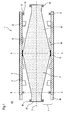
- FIG. 1 shows a roll 1 with a roll cover 8 according to the invention in side view.
- the roll cover according to the invention was applied to a roll body 4 by the method according to the invention.
- the roll cover 8 has a roll side 2 and a paper or wear side 3.
- the roll cover 8 is applied to the roll side 2 on the lateral surface 14 of the roller body 4 and connected thereto.
- the roll cover 8 has a fiber component 5, a matrix component 6 and a filler component 9, wherein the fiber component 5 and the filler component 9 are embedded in the matrix component 6.
- the material composition of the roll cover 8, consisting of fiber component 5, matrix component 6 and filler component 9, changes continuously in the radial direction 7 of the roll 1.
- the fiber component 5 is formed by a single type of fiber, for example in the form of carbon fibers 5.
- the composition of the fiber component changes continuously in the radial direction 7 of the roll cover 8, in which the proportion of carbon fibers 5 in the material composition of fiber component 5, matrix component 6 and filler component 9 in the radial direction 7 of Roll cover 8 from the roll side 2 to the paper or wear side 3 decreases continuously and by the length distribution of the carbon fibers 5 in the radial direction 7 of the roll cover 8 from the roll side 2 to the paper or wear side 3 decreases continuously.
- the matrix component 6 is formed by a first matrix type 10 (shown as a white area) and a second matrix type 11 (shown as a black round dots).
- the first matrix type 10 comprises in the present exemplary embodiment an epoxy resin fraction.
- the second matrix type 11 comprises in the present embodiment, a polyurethane resin portion.
- a roll cover 8 is provided which is dimensionally stable and has an abrasion-resistant paper or wear side 3.
- the filler component 9 (shown as black squares) is formed in the present embodiment by a wear-reducing filler, for example, in the form of nanoparticles 9 made of aluminum oxide or the like.
- the proportion of nanoparticles 9 in the radial direction 7 increases continuously from the roll side 2 towards the paper or wear side 3.
- FIG. 2 shows an arrangement 12 for carrying out the method according to the invention.
- the arrangement is essentially formed by the roll body 4 to be coated with a roll jacket 8 and by an applicator device 18, which is spaced apart from it in the radial direction of the roll body 4.
- roller body 4 of the present embodiment is made of a metallic material. It would also be conceivable that the roller body 8 is at least partially made of a composite material.
- the roller body 4 rotates in the rotational direction 15 about its axial axis of rotation 29 while the applicator 18 moves parallel to the axis of rotation 29 along the direction of movement 16 and optionally additionally can move perpendicular to the axis of rotation 29 along the direction of movement 17.
- the application device 18 has an ejection opening 25 for the exit of loose fiber pieces 26 of the fiber component 5 and an outlet opening 28 for the exit of a mixture 27 of the matrix component 6, the filler component 9 and other components such as. A color component and the like.
- the ejection opening 25 and the outlet opening 28 are set in such a way that the mixture 27 and the loose fiber pieces 26 impinge substantially on the same point of the lateral surface 14 of the roller body 4 and thereby form a fiber composite material.
- the mixture 27 and the loose fiber pieces 26 are thus applied in an injection process in which the loose fiber pieces 26 are embedded in the mixture 27 of matrix component 6, filler component 9 and color component.
- An application of individual components by scattering (not shown) is also possible according to the invention.
- the application device 18 has a feed device 23 for feeding in the fiber component 5.
- the feed device is designed as a feed opening 23 into which the fiber component 5 is introduced.
- the supplied fiber component 5 is in the form of long fiber strands.
- a crushing device 29 is provided between the feed opening 23 and the discharge opening 25, a crushing device 29 is provided.
- the introduced fiber component 5 is comminuted into loose fiber pieces 26 having a defined length distribution.
- the applicator 18 has feed openings 19, 20, 21 and 22 for feeding the matrix component 6, the filler component 9 (also pre-bleached with another component, for example, resin) and the color component.
- the matrix component 6 typically comprises one or more resin types and one or more types of curing agents.
- the resin type (s) of the application device 18 are supplied via the feed opening 19.
- the hardener type or types are supplied to the application device 18 via the feed opening 20.
- the filler component 9 and the color component are supplied to the application device 18 via the feed openings 21 and 22, respectively.
- the supplied matrix component 6, the filler component 9 and the color component are mixed to form the mixture 27, which is injected via the outlet opening 28 onto the roll body 4 to produce a roll cover 8 according to the invention.
- the loose fiber pieces 26 of the fiber component 5 and the mixture 27 of matrix component 6 and filler component 9 by rotating the roller body 4 and by moving the applicator 18 along the direction of movement 16 at different locations applied to the roll body 4, wherein the composition of loose fiber pieces 26 and mixture 27 and the composition of the loose Fasem 26 and / or the mixture 27 itself is set depending on the axial and / or radial position of the location on the roll body 4 to achieve that the material composition of fiber component 5, matrix component 6 and filler component 9 according to the invention, according to the respective requirements of the roll cover 8, at least in sections continuously changes.
- the fiber component 5 is formed by one or more types of fibers, such as glass or carbon or aramid or boron or polypropylene or polyester or PPS or PEEK fibers and / or that the composition the fiber component 5 changes, in which the proportion and / or the diameter and / or the length distribution and / or the orientation of the fiber pieces of at least one fiber type changes.
- the loose fiber pieces have a length distribution of 1 to 10 mm, preferably from 1 to 3 mm and / or from 3 to 10 mm, wherein the length distribution according to the invention depending on the axial and radial position of the location on which these are applied to the roll body 4 may vary or varies.
- the matrix component 6 is formed by one or more resin types and by one or more types of hardeners.
- resin types for example, elastomeric and / or thermoplastic and / or thermosetting resins are conceivable.
- the composition of the matrix component 6 changes, for example, in that the mixing ratio and the components of at least one type of resin and / or at least one hardener component changes, for example the change from a bisphenol A epoxy resin type to a bisphenol F epoxy resin type and / or a variation of aromatic and / or aliphatic amine hardeners.
- the filler component is formed by one or more types of filler, wherein as fillers, for example, wear-reducing fillers and / or viscosity-influencing fillers and / or surface tension influencing fillers and / or conductivity-influencing fillers can be used.
- wear-reducing filler types are carbides or metals or oxides such as metal oxides such as Cr oxide, Fe oxide or Al oxide or fiber pulp of carbon and / or aramid and / or glass in the size range of 1 to 1000 .mu.m, preferably 5 to 100 .mu.m conceivable , Thermoplastics or ionic fillers are conceivable as fillers influencing the surface tension.
- the composition of the filler component changes, for example, in which the proportion and / or the grain size of at least one filler type changes.
- at least one type of filler may have a grain size in the nanometer and / or micrometer and / or millimeter range.
- a typical rubber cover can be applied to the fiber composite roll cover 8 according to the invention, which is crosslinked by vulcanization.
- FIG. 3 shows a further arrangement 30 for carrying out the method according to the invention.
- a plurality of application devices 31, 32 and 33 are provided, which are arranged one behind the other in the circumferential direction of the roll body 4 to be coated with a roll cover 8.
Landscapes
- Rolls And Other Rotary Bodies (AREA)
- Yarns And Mechanical Finishing Of Yarns Or Ropes (AREA)
Abstract

Description
- Die Erfindung betrifft einen Walzenbezug aus einem Faserverbund Material sowie ein Verfahren zu dessen Herstellung.
- Walzenbezüge aus Faserverbund Materialien werden in bahnverarbeitenden Maschinen in vielfältiger Weise eingesetzt. Die anspruchsvollsten Anforderungen werden hierbei im Hinblick auf Druckspannung und dynamische Beanspruchung bei Papiermaschinen an elastische Kalenderbezüge gestellt. Diese Bezüge sind in der Regel aus Faserverbund Material aufgebaut.
- Aus dem Stand der Technik sind hierbei im Wesentlichen zwei Verfahren zur Aufbringung einer Faserverstärkung bekannt.
- Aus der WO 94/09208 ist das sog. Laminierverfahren bekannt, bei dem Faser- und /oder Gewebebänder auf einen Walzenkörper aufgebracht und anschließend mittels Harzen, bspw. Epoxydharzen, zu einem Faserverbund Werkstoff miteinander verbunden werden. Um unterschiedlichen Anforderungen gerecht zu werden, ist ein solcher Walzenbezug aus mehreren unterschiedlich laminierten Schichten aufgebaut.
- Als weitere Auftragsmethode ist das sog. Filament Winding Verfahren bekannt, bei dem Faserbündel auf einen Walzenkörper gewickelt und anschließend mittels Harzen zu einem Faserverbund Werkstoff miteinander verbunden werden.
- Bei der erstgenannten Auftragsmethode besteht der Nachteil darin, dass der fertige Walzenbezug aus unterschiedlichen Schichten aufgebaut ist. Die Grenzfläche zwischen verschiedenen Schichten ist hierbei oftmals, aufgrund der sprungartigen Änderung der Materialeigenschaften, der Ausgangspunkt für Delaminationserscheinungen im Walzenbezug.
- Die zweite Auftragsmethode ist bspw. nicht für die Erzeugung von mit der Papierbahn in Kontakt zu bringende Nutzschichten in Glätteinrichtungen geeignet, da solche Walzenmäntel zu einer ungleichmäßigen Glättung der Papierbahn führen, da die gewickelten Fasern im wesentlichen gleichgerichtet sind.
- Eine zufrieden stellende Glättwirkung kann aber bei applizierten Fasern in Form von Wirrfasern erreicht werden. Somit ist es notwendig, dass die mit dem Filament Winding Verfahren hergestellten Walzenbezüge zusätzlich mit einer oder mehreren laminierten Schichten versehen werden, die die Funktion der Nutzschicht übernimmt. Somit werden auch hier Walzenbezüge geschaffen, die aus mehreren unterschiedlichen Schichten aufgebaut sind.
- Ausgehend von den aus dem Stand der Technik bekannten Walzenbezügen ist es die Aufgabe der vorliegenden Erfindung einen Walzenbezug und ein Verfahren zu dessen Herstellung vorzuschlagen, bei dem die o. g. Nachteile unterbunden sind.
- Die Aufgabe wird erfindungsgemäß durch einen Walzenbezug mit den Merkmalen des Patentanspruch 1 und durch ein Verfahren mit den Merkmalen des Patentanspruchs 22 gelöst.
- Vorteilhafte Ausführungsformen und Weiterbildungen der Erfindung sind in den Unteransprüchen angegeben.
- Die vorliegende Erfindung geht von der Idee aus, dass die Belastbarkeit von Walzenbezügen dadurch gesteigert werden kann, in dem ein stufenartiger Wechsel in den Materialeigenschaften, wie dies das Laminierverfahren zur Folge hat, unterbunden wird. Demzufolge sieht die vorliegende Erfindung einen Faserverbund - Walzenbezug aus einem Material mit einer Faserkomponente und mit einer Matrixkomponente vor, bei dem sich die Materialzusammensetzung aus Faserkomponente und Matrixkomponente quantitativ und qualitativ zumindest abschnittweise kontinuierlich ändert.
- Unter einer Matrixkomponente soll in diesem Zusammenhang das Material oder die Materialzusammensetzung verstanden werden, in die andere gelöste oder ungelöste Materialien eingebettet sind. Im Falle des erfindungsgemäßen Walzenbezugs ist somit die Faserkomponente in die Matrixkomponente eingebettet.
- Durch die Erfindung wird somit zumindest abschnittweise ein Walzenbezug ohne Grenzschichten geschaffen, da sich die Materialzusammensetzung des Walzenbezugs abschnittweise kontinuierlich ändert.
- Somit wird ein Walzenbezug geschaffen, der einen kontinuierlichen Verlauf von kennzeichnenden Eigenschaften wie bspw. E-Modul, Bruchzähigkeit, Abriebbeständigkeit oder Härte aufweist.
- Nach einer bevorzugten Ausführungsform der Erfindung weist das Material des Walzenbezugs eine Füllstoffkomponente auf, wobei sich die Materialzusammensetzung aus Faserkomponente und / oder Matrixkomponente und /oder Füllstoffkomponente zumindest abschnittweise kontinuierlich ändert.
- An einen Walzenbezug werden unterschiedlichste Anforderungen gestellt. So ist es z.B. oftmals notwendig, dass ein Walzenbezug dimensionsstabil ist und gleichzeitig eine hohe Verschleißbeständigkeit aufweist. Die Dimensionsstabilität wird hierbei durch die in radialer Richtung innen liegenden Bereiche realisiert. Die Verschleißbeständigkeit wird hingegen durch die in radialer Richtung außen liegenden Bereiche realisiert.
- Des weiteren gibt es Anwendungen, bei denen es sinnvoll ist, wenn der Walzenbezug sich in axialer Richtung des Walzenkörpers ändernde Eigenschaften aufweist.
- Eine bevorzugte Ausführungsform der Erfindung sieht deshalb vor, dass sich die Materialzusammensetzung in axialer Richtung und / oder in radialer Richtung des Walzenbezugs zumindest abschnittweise kontinuierlich ändert.
- Es sind unterschiedliche Möglichkeiten denkbar, wie sich die Materialzusammensetzung des Walzenbezugsmaterials kontinuierlich ändern kann. Zum einen ist es möglich, dass sich der Anteil an der Materialzusammensetzung zumindest einer der Komponenten ändert, nämlich der Faserkomponente und / oder der Matrixkomponente und / oder der Füllstoffkomponente,.
- So ist es bspw. möglich, dass sich der Anteil der Faserkomponente in radialer Richtung nach außen von 30% auf 5% reduziert, wohingegen sich der Anteil der Matrixkomponente bei gleich bleibendem Anteil der Füllstoffkomponente entsprechend vergrößert.
- Des weiteren ist es denkbar, dass sich die Zusammensetzung einer oder mehrerer der Komponenten ändert.
- So wird die Faserkomponente bevorzugter weise durch einen oder mehrere Fasertypen gebildet.
- Hierbei soll bspw. unter einer Änderung der Zusammensetzung der Faserkomponente verstanden werden, dass sich der Anteil und / oder der Durchmesser und / oder die Längenverteilung und / oder die Orientierung der Fasern zumindest eines Fasertyps ändern.
- Durch die Änderung der verschiedenen Anteile der einzelnen Fasertypen an der Faserkomponente kann ortsabhängig gezielt ein gewünschtes Eigenschaftsprofil des Walzenbezugs eingestellt werden.
- Auch durch die Änderung der Faserdurchmesser, der Längenverteilung und der Orientierung der Fasern kann die Stabilität ortsabhängig beeinflusst werden. So ist die Zugbelastbarkeit bspw. stark abhängig von der Orientierung der Fasem.
- Des weiteren weist die Matrixkomponente bevorzugter weise einen oder mehrere Harztypen und einen oder mehrere Härtertypen auf.
- Hierbei soll bspw. unter einer Änderung der Zusammensetzung der Matrixkomponente verstanden werden, dass sich das Mischungsverhältnis zumindest eines Harztypen und / oder zumindest einer Härterkomponenten in der Matrixkomponente ändert.
- So ist bspw. denkbar dass sich das Mischungsverhältnis zumindest eines Harztypen unter Beibehaltung des Härtertypen in radialer Richtung des Walzenbezugs ändert, in dem der Anteil von Epoxydharz vom Inneren des Walzenbezugs in Richtung zur Außenseite (Papierseite) des Walzenbezug von 100% auf 0% kontinuierlich abnimmt, wohingegen der Anteil von Polyurethanharz umgekehrt vom Inneren des Walzenbezugs in Richtung der Außenseite des Walzenbezugs von 0% auf 100% zunimmt. Somit wird ein Walzenbezug erzeugt, der eine papierseitige Verschleißschicht aus Polyurethanharz und eine Grundschicht aus Epoxydharz aufweist, wobei die beiden Schichten in radialer Richtung kontinuierlich ineinander übergehen.
- Darüber hinaus wird die Füllstoffkomponente bevorzugter weise durch einen oder mehrere Füllstofftypen gebildet wird.
- Hierbei soll bspw. unter einer Änderung der Zusammensetzung der Füllstoffkomponente verstanden werden, dass sich der Anteil und / oder die Korngröße zumindest eines Füllstofftyps ändert.
- Als bevorzugte Fasertypen kommen anorganische Fasem aus Glas, Metall, keramische Fasem, Bor oder organische Fasern bspw. Carbon und / oder Aramid und / oder Polypropylen oder Polyester oder Hochleistungsthermoplaste wie bspw. PPS oder PEEK oder PTFE Fasern in Betracht. So ist es bspw. aufgrund der obigen Ausführungen denkbar, sowohl, wenn die Faserkomponente nur aus einem Fasertyp besteht, den Anteil eines Fasertyps bspw. Glasfasern und damit den Anteil der Faserkomponente an der Materialzusammensetzung kontinuierlich in radialer Richtung zu ändern. Des weiteren ist auch möglich, bei gleich bleibendem Anteil der Faserkomponente in der Materialzusammensetzung aus Faserkomponente und Matrixkomponente den Anteil eines Fasertyps in der Faserkomponente zu erhöhen und den Anteil eines anderen Fasertyps in der Faserkomponente entsprechend zu reduzieren.
- Um auf die Eigenschaften des Walzenbezugs des weiteren gezielt Einfluss nehmen zu können sieht eine bevorzugte Ausführungsform der Erfindung vor, dass zumindest ein Fasertyp durch Faserstücke mit definierter Längenverteilung gebildet wird, die vor dem Einbetten in die Matrixkomponente nicht miteinander verbunden sind.
- Unter Faserstücken soll in diesem Zusammenhang verstanden werden, dass die Fasern nicht als Faserbündel (im Gegensatz zu Filament Winding Prozess) oder als Fasermatten (im Gegensatz zum Laminierprozess) ausgebildet sind. Vielmehr liegen Faserstücke mit definierter Längenverteilung vor dem Einbetten in die Matrixkomponente als einzelne, lose d.h. nicht miteinander verbundene Faserstücke vor.
- Insbesondere für die papierseitige Oberfläche des Walzenbezugs ist es zur Vermeidung von Markierungsneigungen notwendig, dass diese Oberfläche durch Wirrfasern gebildet wird. Demzufolge sieht eine bevorzugte Ausführungsform der Erfindung vor, dass zumindest ein Fasertyp einen Anteil von Faserstücken aufweist, die ungerichtet orientiert in der Matrixkomponente eingebettet sind.
- Eine bevorzugte Ausgestaltung der Erfindung sieht vor, dass zumindest ein Fasertyp aus dem Bereich anorganischer und / oder organischer Fasern (Elastomer, Thermoplaste oder Duroplaste) Faserstücke mit einer Längenverteilung von 0,1 bis 100 mm, bevorzugt von 1 bis 30mm, besonders bevorzugt von 1 bis 3mm und / oder von 3 bis 10 mm, vorzugsweise Fasern aus Aramid und / oder Glas und / oder Carbon aufweist.
- Die verwendeten Harztypen sind vorzugsweise elastomere oder duroplastische Harze. Demzufolge siegt eine Ausführungsform der Erfindung vor, dass zumindest ein Harztyp ein elastomeres oder ein duroplastisches Harz (Epoxide, Cyanatester, Phenolharze) ist, aber auch thermoplastische Werkstoffe (PE, PP, PPS, PEEK,...) und / oder Mischungen derselben.
- Hierbei ist als durolplastisches Harz bspw. Epoxydharz oder Cyanatesterharze auch Phenolharze zu nennen. Insbesondere Bisphenol A Epoxidharze mit aminischen Härter, wobei die Anteile Härter je 100 Teile Harz im Bereich 0 bis 300 Teile betragen (bspw. Ancamine 2390 [Air Products] 107 Teile), insbesondere jedoch 5 bis 40 Teile, besonders bevorzugt 5 bis 25 Teile. Jedoch kann die Vernetzung auch durch Katalysatoren hergestellt werden, die ohne Härter das Epoxidharz dreidimensional vernetzen. Des weiteren werden als elastomere Harze Polyurethanharz oder Gummi verwendet.
- Um bspw. die Eigenschaften der papierseitigen Verschleißschicht gezielt beeinflussen zu können, sehen bevorzugte Ausführungsformen der Erfindung vor, dass als Füllstofftypen Verschleiß mindernde Füllstoffe und / oder die Viskosität beeinflussende Füllstoffe und / oder die Oberflächenspannung beeinflussende Füllstoffe und / oder die Leitfähigkeit beeinflussende Füllstoffe Verwendung finden.
- Als Verschleiß mindernde Füllstofftypen finden bevorzugt Carbide oder Metalle oder Oxide wie bspw. Cr, Fe, Al oder deren Oxide Verwendung, in einem Bereich von 0 bis 100 Gew.%, insbesondere in einem Bereich von 10 bis 60Gew. %, besonders bevorzugt in einem Bereich von 20 bis 50 Gew. %.
- Als die Oberflächenspannung beeinflussende Füllstofftypen finden bevorzugt Thermoplaste oder ionische Füllstoffe Verwendung, in einem Bereich von 0 bis 60 Gew.%, insbesondere 5 bis 20 Gew. %, zur Erreichung einer Oberflächenspannung von 20 bis 70mN/m, vorzugsweise 25 bis 56mN/m, besonders bevorzugt von 25 bis 48mN/m.
- Des weiteren können die Füllstofftypen eine Korngröße im Nanometer- und / oder im Mikrometer- und / oder im Millimeterbereich aufweisen, d.h. es sind sowohl Füllstofftypen denkbar, die nur Korngrößen in Nanometerbereich haben wie auch Füllstofftypen die eine Korngrößenverteilung vom Nanometerbereich bis zum Millimeterbereich haben.
- Nach dem erfindungsgemäßen Verfahren zur Herstellung eines Faserverbund - Walzenbezugs auf einem Walzenkörper, wobei das Material des Walzenbezugs eine Faserkomponente und eine Matrixkomponente aufweist, sind folgende Schritte vorgesehen,
- Aufbringen der Faserkomponente und der Matrixkomponente an einem bestimmten Ort auf dem Walzenkörper, wobei die quantitative und qualitative Materialzusammensetzung aus Faserkomponente und Matrixkomponente abhängig von der axialen und / oder radialen Position des Auftragsorts auf dem Walzenkörper ist,
- Wiederholen der vorgenannten Schritte an einem anderen Ort des Walzenkörpers.
- Eine Ausgestaltung des erfindungsgemäßen Verfahrens sieht vor, dass mit der Faserkomponente und der Matrixkomponente ebenfalls eine Füllstoffkomponente aufgebracht wird.
- Besonders einfach und effektiv kann eine kontinuierliche Änderung der Faserkomponente eingestellt werden, wenn die Faserkomponente durch einen oder mehrere Fasertypen gebildet wird, wobei vor dem Aufbringen der Faserkomponente bei zumindest einem Fasertyp lose Faserstücke mit einer definierten Längenverteilung erzeugt werden. Des weiteren ist es besonders einfach möglich die losen Faserstücke mit definierter Längenverteilung ungerichtet zu verteilen, wodurch der Walzenbezug zum einen eine geringere Markierungsneigung aufweist und zum anderen in alle Richtungen der Schicht in der die losen Fasern angeordnet sind eine gleiche Stabilität hat.
- Besonders einfach und kostengünstig ist das erfindungsgemäße Verfahren, wenn die Faserkomponente und / oder die Matrixkomponente und / oder die Füllstoffkomponente durch einen Spritzprozess aufgetragen werden; eine Aufbringung durch Kombination von Spritzen und Aufstreuen der Füllstoffe ist ebenfalls möglich.
- Nach einer Ausgestaltung der Erfindung ist die Zusammensetzung und / oder der Anteil der aufgetragenen Faserkomponente und / oder der aufgetragenen Matrixkomponente und / oder der aufgetragenen Füllstoffkomponente abhängig von der axialen und / oder radialen Position des Auftragsorts auf dem Walzenkörper.
- Eine konkrete Ausgestaltung des Verfahrens sieht vor, dass das Material des Walzenbezugs mit einer Auftragsvorrichtung auf den Walzenkörper aufgetragen wird, wobei sich die Auftragsvorrichtung in axialer und / oder in radialer Richtung des Walzenkörpers bewegen kann.
- Durch die Bewegung der Auftragsvorrichtung in axialer Richtung des Walzenkörpers kann die Materialzusammensetzung in axialer Richtung eingestellt werden. Diese kann sowohl in axialer Richtung konstant sein wie auch varüeren. In die Auftragsmenge der Auftragsvorrichtung geht des weiteren die Vorschubgeschwindigkeit der Auftragsvorrichtung in axialer Richtung ein.
- Durch die Bewegung der Auftragsvorrichtung in radialer Richtung des Walzenkörpers kann der Abstand zum Walzenkörper eingestellt und somit gezielt die Durchmischung und die Aufpralldichte bspw. der Faserkomponente, der Matrixkomponente oder der Füllstoffkomponente gesteuert werden.
- Eine bevorzugte Ausgestaltung der Erfindung sieht vor, dass der Walzenkörper beim Auftragen um seine axiale Achse rotiert, wodurch eine in Umfangrichtung gleichmäßige Dicke des Walzenbezugs herstellbar ist. Hierbei stellt die Umfanggeschwindigkeit des Walzenkörpers eine wichtige Einflussgröße für die Auftragsmenge dar.
- Nach einer bevorzugten Ausführungsform der Erfindung sind mehrere Auftragsvorrichtungen vorgesehen, die bspw. in Umfangrichtung an verschiedenen Positionen angeordnet sind. Durch diese Ausgestaltung ist es möglich, die kontinuierliche Vermengung von Faserkomponente, Matrixkomponente und Füllstoffkomponente weiter zu verbessern.
- Nach einer weiteren Ausführungsform des erfindungsgemäßen Verfahrens wird der Walzenbezug in einer Lage oder in mehreren Lagen aufgetragen.
- Um während dem Auftragungsverfahren in den Walzenbezug eingeschlossene Gase zu entfemen, sieht eine besonders bevorzugte Weiterbildung des erfindungsgemäßen Verfahrens vor, dass der Walzenbezug in einer Unter- oder Überdruckdruckatmosphäre ausgehärtet wird. Dadurch kann bspw. während der Gelierphase und dem folgenden Aushärtungsprozess die aus dem Faserverbund-Material freiwerdende Luft durch den Unterdruck abgesaugt werden, wodurch ein blasen- und porenfreier Walzenbezug hergestellt werden kann. Ebenso ist eine Aushärtung mittels elektromagnetischer Strahlen wie bspw. UV-Licht oder Mikrowellen möglich.
- Nachfolgend wird die Erfindung anhand der folgenden schematischen nicht maßstäblichen Zeichnungen weiter erläutert werden. Es zeigen:
- Figur 1 eine Walze mit Walzenkörper und erfindungsgemäßem Walzenbezug in Seitenansicht,
- Figur 2 eine Vorrichtung zur Durchführung des erfindungsgemäßen Herstellungsverfahrens,
- Figur 3 eine Vorrichtung zur Durchführung des erfindungsgemäßen Herstellungsverfahrens mit mehreren Auftragsvorrichtungen.
- Die Figur 1 zeigt eine Walze 1 mit einem erfindungsgemäßen Walzenbezug 8 in Seitenansicht. Der erfindungsgemäße Walzenbezug wurde auf einem Walzenkörper 4 nach dem erfindungsgemäßen Verfahren aufgebracht.
- Der Walzenbezug 8 weist eine Walzenseite 2 und eine Papier- oder Verschleißseite 3 auf. Der Walzenbezug 8 ist mit der Walzenseite 2 auf der Mantelfläche 14 des Walzenkörper 4 aufgebracht und mit dieser verbunden. Der Walzenbezug 8 weist eine Faserkomponente 5, eine Matrixkomponente 6 und eine Füllstoffkomponente 9 auf, wobei die Faserkomponente 5 und die Füllstoffkomponente 9 in die Matrixkomponente 6 eingebettet sind.
- Erfindungsgemäß ändert sich die Materialzusammensetzung des Walzenbezugs 8 bestehend aus Faserkomponente 5, Matrixkomponente 6 und Füllstoffkomponente 9 kontinuierlich in radialer Richtung 7 der Walze 1.
- Im vorliegenden Ausführungsbeispiel wird die Faserkomponente 5 durch einen einzigen Fasertypen bspw. in Form von Carbon- Fasern 5 gebildet. Wie aus der Figur 1 zu entnehmen ist, ändert sich die Zusammensetzung der Faserkomponente kontinuierlich in radialer Richtung 7 des Walzenbezugs 8, in dem der Anteil an Carbon-Fasern 5 in der Materialzusammensetzung aus Faserkomponente 5, Matrixkomponente 6 und Füllstoffkomponente 9 in radialer Richtung 7 des Walzenbezugs 8 von der Walzenseite 2 zur Papier- oder Verschleißseite 3 kontinuierlich abnimmt und indem die Längenverteilung der Carbon- Fasern 5 in radialer Richtung 7 des Walzenbezug 8 von der Walzenseite 2 zur Papier- oder Verschleißseite 3 kontinuierlich abnimmt.
- Des weiteren wird im vorliegenden Ausführungsbeispiel die Matrixkomponente 6 durch einen ersten Matrixtyp 10 (als weiße Fläche dargestellt) und durch einen zweiten Matrixtyp 11 (als schwarze runde Punkte dargestellt) gebildet.
- Der erste Matrixtyp 10 umfasst im vorliegenden Ausführungsbeispiel einen Epoxydharzanteil. Der zweite Matrixtyp 11 umfasst im vorliegenden Ausführungsbeispiel einen Polyurethanharzanteil.
- Wie aus der Figur 1 zu erkennen ist, nimmt der Anteil des ersten Matrixtyp 10 in axialer Richtung 7 von der Walzenseite 2 zur Papier- oder Verschleißseite 3 hin kontinuierlich ab. Umgekehrt nimmt der Anteil des zweiten Matrixtyp 11 in radialer Richtung 7 von der Walzenseite 2 zur Papier- oder Verschleißseite 3 hin kontinuierlich zu. Somit wird ein Walzenbezug 8 geschaffen, der dimensionsstabil ist und eine abrasionsresistive Papier- oder Verschleißseite 3 aufweist.
- Die Füllstoffkomponente 9 (als schwarze Vierecke dargestellt) wird im vorliegenden Ausführungsbeispiel durch einen verschleiß mindernden Füllstoff bspw. in Form Nanopartikeln 9 aus Aluminiumoxid oder dgl. gebildet.
- Wie aus der Figur 1 zu erkennen ist, nimmt der Anteil der Nanopartikel 9 in radialer Richtung 7 von der Walzenseite 2 zur Papier- oder Verschleißseite 3 hin kontinuierlich zu.
- Die Figur 2 zeigt eine Anordnung 12 zur Durchführung des erfindungsgemäßen Verfahrens.
- Die Anordnung wird im wesentlichen durch den mit einem Walzenmantel 8 zu beschichtenden Walzenkörper 4 und durch eine Auftragsvorrichtung 18 gebildet, die in radialer Richtung des Walzenkörpers 4 zu diesem beabstandet ist.
- Des weiteren ist ein Teil eines bereits auf dem Walzenkörper 4 gebildeten Walzenbezugs 8 zu erkennen. Der Walzenkörper 4 des vorliegenden Ausführungsbeispiels ist aus einem metallischen Werkstoff hergestellt. Es wäre aber auch denkbar, das der Walzenkörper 8 zumindest teilweise aus einem Verbundwerkstoff hergestellt ist.
- Während dem Auftragsvorgang dreht sich der Walzenkörper 4 in Drehrichtung 15 um seine axiale Drehachse 29 während sich die Auftragsvorrichtung 18 parallel zur Drehachse 29 entlang der Bewegungsrichtung 16 bewegt und optional zusätzlich senkrecht zur Drehachse 29 entlang der Bewegungsrichtung 17 bewegen kann.
- Die Auftragsvorrichtung 18 weist eine Auswurfsöffnung 25 zum Austritt von losen Faserstücken 26 der Faserkomponente 5 und eine Austrittsöffnung 28 zum Austritt eines Gemisches 27 aus der Matrixkomponente 6, der Füllstoffkomponente 9 und weiteren Komponenten wie bspw. einer Farbkomponente und dgl. auf. Die Auswurföffnung 25 und die Austrittsöffnung 28 sind dergestalt eingestellt, dass das Gemisch 27 und die losen Faserstücke 26 im wesentlichen auf die gleiche Stelle der Mantelfläche 14 des Walzenkörpers 4 auftreffen und dabei einen Faserverbund-Werkstoff bilden. Das Gemisch 27 und die losen Faserstücke 26 werden somit in einem Spritzprozess aufgetragen, bei welchem die losen Faserstücke 26 in das Gemisch 27 aus Matrixkomponente 6, Füllstoffkomponente 9 und Farbkomponente eingebettet werden. Eine Aufbringung einzelner Komponenten durch Aufstreuen (nicht dargestellt) ist erfindungsgemäß ebenso möglich.
- Des weiteren weist die Auftragsvorrichtung 18 eine Einspeisvorrichtung 23 zum Einspeisen der Faserkomponente 5 auf. Im vorliegenden Ausführungsbeispiel ist die Einspeisvorrichtung als Einspeisöffnung 23 ausgeführt, in weiche die Faserkomponente 5 eingeführt wird. Im vorliegenden Ausführungsbeispiel liegt die zugeführte Faserkomponente 5 in Form von langen Fasersträngen vor. Zwischen der Einspeisöffnung 23 und der Auswurföffnung 25 ist eine Zerkleinerungsvorrichtung 29 vorgesehen. In der Zerkleinerungsvorrichtung 29 wird die eingeführte Faserkomponente 5 zu losen Faserstücken 26 mit definierter Längenverteilung zerkleinert.
- Darüber hinaus weist die Auftragsvorrichtung 18 Zuführöffnungen 19, 20, 21 und 22 zum Zuführen der Matrixkomponente 6, der Füllstoffkomponente 9 (auch mit einer weiteren Komponente bspw. Harz vorgeschischt) und der Farbkomponente auf. Die Matrixkomponente 6 umfasst üblicherweise einen oder mehrere Harztypen und einen oder mehrere Härtertypen. Im vorliegenden Ausführungsbeispiel werden der oder die Harztypen der Auftragsvorrichtung 18 über die Zuführöffnung 19 zugeführt. Des weiteren werden der oder die Härtertypen der Auftragsvorrichtung 18 über die Zuführöffnung 20 zugeführt. Die Füllstoffkomponente 9 und die Farbkomponente werden der Auftragsvorrichtung 18 über die Zuführöffnungen 21 bzw. 22 zugeführt.
- In der Auftragsvorrichtung 18 selbst werden die zugeführte Matrixkomponente 6, die Füllstoffkomponente 9 und die Farbkomponente zu dem Gemisch 27 vermischt, welches über die Austrittsöffnung 28 auf den Walzenkörper 4 zur Erzeugung eines erfindungsgemäßen Walzenbezugs 8 gespritzt wird.
- Bei der Herstellung des Faserverbund - Walzenbezugs 8 auf dem Walzenkörper 4, werden die losen Faserstücke 26 der Faserkomponente 5 und das Gemisch 27 aus Matrixkomponente 6 und Füllstoffkomponente 9 durch Drehung des Walzenkörpers 4 und durch Bewegung der Auftragsvorrichtung 18 entlang der Bewegungsrichtung 16 an unterschiedlichen Orten auf dem Walzenkörper 4 aufgebracht, wobei die Zusammensetzung aus losen Faserstücken 26 und Gemisch 27 sowie die Zusammensetzung der losen Fasem 26 und / oder des Gemisches 27 selbst abhängig von der axialen und / oder radialen Position des Orts auf dem Walzenkörper 4 eingestellt wird um zu erreichen, dass sich die Materialzusammensetzung aus Faserkomponente 5, Matrixkomponente 6 und Füllstoffkomponente 9 erfindungsgemäß, entsprechend den jeweiligen Anforderungen an den Walzenbezug 8, zumindest abschnittweise kontinuierlich ändert.
- So ist es möglich, dass die Faserkomponente 5 durch einen oder mehrere Fasertypen, wie bspw Glas- oder Carbon- oder Aramid- oder Bor- oder Polypropylen-oder Polyester- oder PPS- oder PEEK- Fasern gebildet wird und / oder dass sich die Zusammensetzung der Faserkomponente 5 ändert, in dem sich der Anteil und / oder der Durchmesser und / oder die Längenverteilung und / oder die Orientierung der Faserstücke zumindest eines Fasertyps ändert. Bevorzugt weisen die losen Faserstücke eine Längenverteilung von 1 bis 10 mm, bevorzugt von 1 bis 3mm und /oder von 3 bis 10 mm auf, wobei die Längenverteilung erfindungsgemäß abhängig von der axialen und radialen Position der Orts auf den diese auf den Walzenkörper 4 aufgetragen werden variieren kann oder variiert.
- Wie bereits erwähnt wird die Matrixkomponente 6 durch einen oder mehrere Harztypen und durch einen oder mehrere Härtertypen gebildet. Als Harztypen sind bspw. elastomere und / oder thermoplastische und / oder duroplastische Harze denkbar. Die Zusammensetzung der Matrixkomponente 6 ändert sich bspw. dadurch, in dem sich das Mischungsverhältnis und die Komponenten zumindest eines Harztypen und / oder zumindest einer Härterkomponenten ändert, bspw. den Wechsel von einem Bisphenol A Epoxidharztyp zu einem Bisphenol F Epoxidharztyp und / oder einer Variation von aromatischen und / oder aliphatischen Aminhärtern.
- Des weiteren wird die Füllstoffkomponente durch einen oder mehrere Füllstofftypen gebildet, wobei als Füllstofftypen bspw. Verschleiß mindernde Füllstoffe und / oder die Viskosität beeinflussende Füllstoffe und / oder die Oberflächenspannung beeinflussende Füllstoffe und / oder die Leitfähigkeit beeinflussende Füllstoffe Verwendung finden können. Als Verschleiß mindernde Füllstofftypen sind Carbide oder Metalle oder Oxide wie bspw. Metalloxide wie Cr-Oxid, Fe-Oxid oder Al-Oxid oder Faserpulp aus Carbon und / oder Aramid und / oder Glas im Größenbereich von 1 bis 1000µm, vorzugsweise 5 bis 100µm denkbar. Als die Oberflächenspannung beeinflussende Füllstofftypen sind Thermoplaste oder ionische Füllstoffe denkbar. Die Zusammensetzung der Füllstoffkomponente ändert sich hierbei bspw., in dem sich der Anteil und / oder die Korngröße zumindest eines Füllstofftyps ändert. Hierbei kann zumindest ein Füllstofftyp eine Komgröße im Nanometer- und / oder im Mikrometer-und / oder im Millimeterbereich aufweisen.
- Selbstverständlich können mit dem erfindungsgemäßen Verfahren unabhängig voneinander mehrere Schichten mit zueinander korrespondierenden Außen- und Innendurchmessem hergestellt werden, die anschließend durch Adhäsive oder Haftvermittler miteinander verbunden werden.
- Des weiteren kann auf den erfindungsgemäßen Faser-Verbund Walzenbezug 8 ein typischer Gummibezug aufgebracht werden, welcher durch Vulkanisieren vemetzt wird.
- Die Figur 3 zeigt eine weitere Anordnung 30 zur Durchführung des erfindungsgemäßen Verfahrens.
- Gemäß der in der Figur 3 gezeigten Anordnung sind mehrere Auftragsvorrichtungen 31, 32 und 33 vorgesehen, die in Umfangrichtung des mit einem Walzenbezug 8 zu beschichtenden Walzenkörpers 4 hintereinander liegend angeordnet sind.
-
- 1
- Walze
- 2
- Walzenseite
- 3
- Verschleißseite
- 4
- Walzenkörper
- 5
- Faserkomponente
- 6
- Matrixkomponente
- 7
- radiale Richtung
- 8
- Walzenbezug
- 9
- Füllstoffkomponente
- 10
- erster Matrixtyp
- 11
- zweiter Matrixtyp
- 12
- Anordnung zur Durchführung des erfindungsgemäßen Verfahrens
- 14
- Mantelfläche
- 15
- Drehrichtung
- 16
- Bewegungsrichtung
- 17
- Bewegungsrichtung
- 18
- Auftragsvorrichtung
- 19
- Zuführöffnung
- 20
- Zuführöffnung
- 21
- Zuführöffnung
- 22
- Zuführöffnung
- 23
- Einspeisöffnung
- 25
- Auswurföffnung
- 26
- lose Faserstücke
- 27
- Gemisch
- 28
- Austrittsöffnung
- 29
- Zerkleinerungsvorrichtung
- 30
- Anordnung zur Durchführung des erfindungsgemäßen Verfahrens
- 31
- Auftragsvorrichtung
- 32
- Auftragsvorrichtung
- 33
- Auftragsvorrichtung
Claims (32)
- Faserverbund - Walzenbezug für den Einsatz in Flächenmaterial verarbeitenden Maschinen, wobei das Material des Walzenbezugs eine Faserkomponente und eine Matrixkomponente aufweist,
dadurch gekennzeichnet,
dass sich die Materialzusammensetzung aus Faserkomponente und Matrixkomponente zumindest abschnittweise kontinuierlich ändert. - Faserverbund - Walzenbezug nach Anspruch 1,
dadurch gekennzeichnet,
dass das Material des Walzenbezugs eine Füllstoffkomponente aufweist, wobei sich die Materialzusammensetzung aus Faserkomponente und / oder Matrixkomponente und / oder Füllstoffkomponente zumindest abschnittweise kontinuierlich ändert. - Faserverbund - Walzenbezug nach einem der Ansprüche 1 bis 2,
dadurch gekennzeichnet,
dass sich die Zusammensetzung und / oder der Anteil der Faserkomponente und / oder der Matrixkomponente und / oder der Füllstoffkomponente kontinuierlich ändert. - Faserverbund - Walzenbezug nach einem der Ansprüche 1 bis 3,
dadurch gekennzeichnet,
dass sich die Zusammensetzung in axialer Richtung und / oder in radialer Richtung der Walzenbezugs zumindest abschnittweise kontinuierlich ändert. - Faserverbund - Walzenbezug nach einem der Ansprüche 1 bis 4,
dadurch gekennzeichnet,
dass die Faserkomponente durch einen oder mehrere Fasertypen gebildet wird. - Faserverbund - Walzenbezug nach Anspruch 5,
dadurch gekennzeichnet,
dass ein Fasertyp durch anorganische Fasern bspw. aus Glas, Metall, keramische Fasern, Bor oder organische Fasern wie bspw. Carbon und / oder Aramid und / oder Polypropylen oder Polyester oder Hochleistungsthermoplaste wie bspw. PPS oder PEEK oder PTFE Fasern gebildet wird. - Faserverbund - Walzenbezug nach Anspruch 5 oder 6,
dadurch gekennzeichnet,
dass sich die Zusammensetzung der Faserkomponente ändert, in dem sich der Anteil und / oder der Durchmesser und / oder die Längenverteilung und / oder die Orientierung der Fasern zumindest eines Fasertyps ändert. - Faserverbund - Walzenbezug nach Anspruch 5,6 oder 7,
dadurch gekennzeichnet,
dass zumindest ein Fasertyp durch lose Faserstücke mit definierter Längenverteilung gebildet wird, die vor dem Einbetten in die Matrixkomponente nicht miteinander verbunden sind. - Faserverbund - Walzenbezug nach einem der Ansprüche 5 bis 8,
dadurch gekennzeichnet,
dass zumindest ein Fasertyp einen Anteil von Faserstücken aufweist, die nicht gerichtet in die Matrixkomponente eingebettet sind. - Faserverbund - Walzenbezug nach einem der Ansprüche 5 bis 9,
dadurch gekennzeichnet,
dass zumindest ein Fasertyp Faserstücke mit einer Längenverteilung von 1 bis 10 mm, bevorzugt von 1 bis 3mm und / oder von 3 bis 10 mm aufweist. - Faserverbund - Walzenbezug nach einem der Ansprüche 1 bis 10,
dadurch gekennzeichnet,
dass die Matrixkomponente einen oder mehrere Harztypen und einen oder mehrere Härtertypen umfasst. - Faserverbund - Walzenbezug nach Anspruch 11,
dadurch gekennzeichnet,
dass ein Harztyp ein elastomeres oder ein duroplastisches Harz (Epoxide, Cyanatester, Phenolharze) und / oder ein thermoplastische Werkstoff (PE, PP, PPS, PEEK,...) und / oder eine Mischung derselben ist. - Faserverbund - Walzenbezug nach Anspruch 12,
dadurch gekennzeichnet,
dass das durolplastische Harz Epoxydharz ist. - Faserverbund - Walzenbezug nach Anspruch 12,
dadurch gekennzeichnet,
dass das elastomere Harz Polyurethanharz oder Gummi ist. - Faserverbund - Walzenbezug nach einem der Ansprüche 11 bis 14,
dadurch gekennzeichnet,
dass sich die Zusammensetzung der Matrixkomponente ändert, in dem sich das Mischungsverhältnis zumindest eines Harztypen und / oder zumindest einer Härterkomponenten ändert. - Faserverbund - Walzenbezug nach einem der Ansprüche 2 bis 15,
dadurch gekennzeichnet,
dass die Füllstoffkomponente durch einen oder mehrere Füllstofftypen gebildet wird. - Faserverbund - Walzenbezug nach Anspruch 16,
dadurch gekennzeichnet,
dass als Füllstofftypen Verschleiß mindernde Füllstoffe und / oder die Viskosität beeinflussende Füllstoffe und / oder die Oberflächenspannung beeinflussende Füllstoffe und / oder die Leitfähigkeit beeinflussende Füllstoffe Verwendung finden. - Faserverbund - Walzenbezug nach Anspruch 17,
dadurch gekennzeichnet,
dass Verschleiß mindernde Füllstofftypen Carbide oder Metalle oder Oxide oder Faserpulp aus Carbon und / oder Aramid und / oder Glas im Größenbereich von 1 bis 1000µm, vorzugsweise 5 bis 100µm sind. - Faserverbund - Walzenbezug nach Anspruch 17,
dadurch gekennzeichnet,
dass die Oberflächenspannung beeinflussende Füllstofftypen Thermoplaste oder ionische Füllstoffe sind. - Faserverbund - Walzenbezug nach einem der Ansprüche 17 bis 19,
dadurch gekennzeichnet,
dass sich die Zusammensetzung der Füllstoffkomponente ändert, in dem sich der Anteil und / oder die Korngröße zumindest eines Füllstofftyps ändert. - Faserverbund - Walzenbezug nach einem der Ansprüche 17 bis 20,
dadurch gekennzeichnet,
dass zumindest ein Füllstofflyp eine Korngröße im Nanometer- und / oder im Mikrometer- und / oder im Millimeterbereich aufweist. - Verfahren zur Herstellung eines Faserverbund - Walzenbezugs auf einem Walzenkörper, wobei das Material des Walzenbezugs eine Faserkomponente und eine Matrixkomponente aufweist, mit folgenden Schritten,- Aufbringen der Faserkomponente und der Matrixkomponente an einem bestimmten Ort auf dem Walzenkörper, wobei die Zusammensetzung aus Faserkomponente und Matrixkomponente abhängig von der axialen und / oder radialen Position des Orts auf dem Walzenkörper ist,- Wiederholen der vorgenannten Schritte an einem anderen Ort des Walzenkörpers.
- Verfahren nach Anspruch 22,
dadurch gekennzeichnet,
dass mit der Faserkomponente und der Matrixkomponente ebenfalls eine Füllstoffkomponente aufgebracht wird. - Verfahren nach einem der Ansprüche 22 bis 23,
dadurch gekennzeichnet,
dass die Faserkomponente und / oder die Matrixkomponente und l oder die Füllstoffkomponente durch einen Spritzprozess aufgetragen werden. - Verfahren nach einem der Ansprüche 22 bis 24,
dadurch gekennzeichnet,
dass die Zusammensetzung und / oder der Gehalt der Faserkomponente und /oder der Matrixkomponente und / oder der Füllstofflcomponente abhängig von der axialen und / oder radialen Position des Orts auf dem Walzenkörper ist, auf den aufgetragen wird. - Verfahren nach einem der Ansprüche 22 bis 25,
dadurch gekennzeichnet,
dass das Material der Walzenbezugs mit einer Auftragsvorrichtung auf den Walzenkörper aufgetragen wird, wobei sich die Auftragsvorrichtung in axialer und / oder in radialer Richtung des Walzenkörpers bewegen kann. - Verfahren nach einem der Ansprüche 22 bis 26,
dadurch gekennzeichnet,
dass mehrere Auftragsvorrichtungen vorgesehen sind. - Verfahren nach einem der Ansprüche 22 bis 27,
dadurch gekennzeichnet,
dass der Walzenkörper beim Auftragen um seine axiale Achse rotiert. - Verfahren nach einem der Ansprüche 22 bis 28,
dadurch gekennzeichnet,
dass der Walzenbezug in einer Lage oder in mehreren Lagen aufgetragen wird. - Verfahren nach einem der Ansprüche 22 bis 29,
dadurch gekennzeichnet,
dass der Walzenbezug in einer Unter- oder Überdruckatmosphäre ausgehärtet wird. - Verfahren nach einem der Ansprüche 22 bis 30,
dadurch gekennzeichnet,
dass die Faserkomponente durch einen oder mehrere Fasertypen gebildet wird, wobei vor dem Aufbringen der Faserkomponente bei zumindest einem Fasertypen Fasern mit definierten Längen erzeugt werden. - Vorrichtung zur Durchführung des Verfahrens nach einem der Ansprüche 22 bis 31.
Applications Claiming Priority (1)
| Application Number | Priority Date | Filing Date | Title |
|---|---|---|---|
| DE102004025116A DE102004025116A1 (de) | 2004-05-21 | 2004-05-21 | Faserverbund Walzenbezug |
Publications (3)
| Publication Number | Publication Date |
|---|---|
| EP1612329A1 true EP1612329A1 (de) | 2006-01-04 |
| EP1612329B1 EP1612329B1 (de) | 2009-06-24 |
| EP1612329B2 EP1612329B2 (de) | 2013-01-09 |
Family
ID=35124569
Family Applications (1)
| Application Number | Title | Priority Date | Filing Date |
|---|---|---|---|
| EP05103508A Expired - Lifetime EP1612329B2 (de) | 2004-05-21 | 2005-04-28 | Faserverbund Walzenbezug |
Country Status (3)
| Country | Link |
|---|---|
| EP (1) | EP1612329B2 (de) |
| AT (1) | ATE434683T1 (de) |
| DE (2) | DE102004025116A1 (de) |
Cited By (7)
| Publication number | Priority date | Publication date | Assignee | Title |
|---|---|---|---|---|
| WO2010079261A1 (en) | 2009-01-07 | 2010-07-15 | Metso Paper, Inc. | A roll of a fiber web machine and a fiber web calender |
| WO2011035969A1 (de) * | 2009-09-23 | 2011-03-31 | Voith Patent Gmbh | Walzenbezug |
| CN101454505B (zh) * | 2006-06-30 | 2011-11-09 | 美卓造纸机械公司 | 弹性辊覆层、带覆层的辊和制造带覆层辊的方法 |
| WO2013160117A1 (de) * | 2012-04-27 | 2013-10-31 | Voith Patent Gmbh | Walze und verfahren zu deren herstellung |
| CN104204347A (zh) * | 2012-03-30 | 2014-12-10 | 福伊特专利公司 | 辊包覆物 |
| CN104220670A (zh) * | 2012-03-30 | 2014-12-17 | 福伊特专利公司 | 制造辊包覆物的方法以及辊包覆物 |
| CN113167027A (zh) * | 2018-12-04 | 2021-07-23 | 安德里茨库斯特斯有限责任公司 | 辊子及辊子的制造方法 |
Families Citing this family (5)
| Publication number | Priority date | Publication date | Assignee | Title |
|---|---|---|---|---|
| DE102006021035B4 (de) * | 2006-04-27 | 2014-03-06 | Paul Sauer Gmbh & Co. Walzenfabrik Kg | Walze mit elastomerer Beschichtung |
| DE102009000738A1 (de) * | 2009-02-10 | 2010-08-12 | Voith Patent Gmbh | Biegeeinstellwalze |
| DE102009028210A1 (de) * | 2009-08-04 | 2011-02-17 | Voith Patent Gmbh | Selbstkonditionierende Walzenbeschabung |
| DE102012205221A1 (de) | 2012-03-30 | 2013-10-02 | Voith Patent Gmbh | Walzenbezug |
| DE102015213512A1 (de) * | 2015-07-17 | 2017-01-19 | Voith Patent Gmbh | Verfahren zur Herstellung eines Walzenbezugs |
Citations (7)
| Publication number | Priority date | Publication date | Assignee | Title |
|---|---|---|---|---|
| EP0487477A1 (de) * | 1990-11-19 | 1992-05-27 | Valmet Paper Machinery Inc. | Verfahren zur Beschichtung einer Walze und Walzenbezug |
| EP0487447A1 (de) | 1990-11-17 | 1992-05-27 | HILTI Aktiengesellschaft | Hartmetall. bzw. hartstoffbestückte Bohr-, Meissel-und Trennwerkzeuge |
| WO1994009208A1 (en) | 1992-10-16 | 1994-04-28 | Beloit Technologies, Inc. | A method of manufacturing a cover for a press roll |
| EP0924337A2 (de) * | 1997-12-17 | 1999-06-23 | Voith Sulzer Papiertechnik Patent GmbH | Presswalze |
| DE19925421A1 (de) | 1999-06-02 | 2000-12-07 | Voith Sulzer Papiertech Patent | Elastische Walze und Verfahren zum Herstellen einer solchen |
| US6319185B1 (en) | 1999-03-31 | 2001-11-20 | Voith Sulzer Papiertechnik Patent Gmbh | Resilient roll and process for producing such a roll |
| US20020045523A1 (en) | 2000-09-18 | 2002-04-18 | Voith Paper Patent Gmbh | Elastic roll |
-
2004
- 2004-05-21 DE DE102004025116A patent/DE102004025116A1/de not_active Withdrawn
-
2005
- 2005-04-28 EP EP05103508A patent/EP1612329B2/de not_active Expired - Lifetime
- 2005-04-28 DE DE502005007553T patent/DE502005007553D1/de not_active Expired - Lifetime
- 2005-04-28 AT AT05103508T patent/ATE434683T1/de active
Patent Citations (7)
| Publication number | Priority date | Publication date | Assignee | Title |
|---|---|---|---|---|
| EP0487447A1 (de) | 1990-11-17 | 1992-05-27 | HILTI Aktiengesellschaft | Hartmetall. bzw. hartstoffbestückte Bohr-, Meissel-und Trennwerkzeuge |
| EP0487477A1 (de) * | 1990-11-19 | 1992-05-27 | Valmet Paper Machinery Inc. | Verfahren zur Beschichtung einer Walze und Walzenbezug |
| WO1994009208A1 (en) | 1992-10-16 | 1994-04-28 | Beloit Technologies, Inc. | A method of manufacturing a cover for a press roll |
| EP0924337A2 (de) * | 1997-12-17 | 1999-06-23 | Voith Sulzer Papiertechnik Patent GmbH | Presswalze |
| US6319185B1 (en) | 1999-03-31 | 2001-11-20 | Voith Sulzer Papiertechnik Patent Gmbh | Resilient roll and process for producing such a roll |
| DE19925421A1 (de) | 1999-06-02 | 2000-12-07 | Voith Sulzer Papiertech Patent | Elastische Walze und Verfahren zum Herstellen einer solchen |
| US20020045523A1 (en) | 2000-09-18 | 2002-04-18 | Voith Paper Patent Gmbh | Elastic roll |
Cited By (9)
| Publication number | Priority date | Publication date | Assignee | Title |
|---|---|---|---|---|
| CN101454505B (zh) * | 2006-06-30 | 2011-11-09 | 美卓造纸机械公司 | 弹性辊覆层、带覆层的辊和制造带覆层辊的方法 |
| WO2010079261A1 (en) | 2009-01-07 | 2010-07-15 | Metso Paper, Inc. | A roll of a fiber web machine and a fiber web calender |
| WO2011035969A1 (de) * | 2009-09-23 | 2011-03-31 | Voith Patent Gmbh | Walzenbezug |
| CN104204347A (zh) * | 2012-03-30 | 2014-12-10 | 福伊特专利公司 | 辊包覆物 |
| CN104220670A (zh) * | 2012-03-30 | 2014-12-17 | 福伊特专利公司 | 制造辊包覆物的方法以及辊包覆物 |
| WO2013160117A1 (de) * | 2012-04-27 | 2013-10-31 | Voith Patent Gmbh | Walze und verfahren zu deren herstellung |
| CN104254646A (zh) * | 2012-04-27 | 2014-12-31 | 福伊特专利公司 | 辊以及制造辊的方法 |
| CN113167027A (zh) * | 2018-12-04 | 2021-07-23 | 安德里茨库斯特斯有限责任公司 | 辊子及辊子的制造方法 |
| CN113167027B (zh) * | 2018-12-04 | 2023-08-29 | 安德里茨库斯特斯有限责任公司 | 辊子及辊子的制造方法 |
Also Published As
| Publication number | Publication date |
|---|---|
| EP1612329B1 (de) | 2009-06-24 |
| DE502005007553D1 (de) | 2009-08-06 |
| DE102004025116A1 (de) | 2005-12-08 |
| ATE434683T1 (de) | 2009-07-15 |
| EP1612329B2 (de) | 2013-01-09 |
Similar Documents
| Publication | Publication Date | Title |
|---|---|---|
| DE69634136T2 (de) | Beschichtete rolle und verfahren zu ihrer herstellung | |
| EP1310316B1 (de) | Sägegarn | |
| EP1612329B2 (de) | Faserverbund Walzenbezug | |
| DE4226789A1 (de) | Faserverstärkte Kunststoffwalze mit äußerer, verschleißfester, füllerhaltiger Kunststoffschicht | |
| EP0655561A1 (de) | Mit Fasern verstärkte Kunststoffwalze mit Rautierung | |
| EP0229983A2 (de) | Schleifscheibe mit Dämpfung | |
| EP1943369B1 (de) | Verfahren zur beschichtung eines bauteils | |
| EP1976697B1 (de) | Verfahren zur herstellung eines verkleidungselements | |
| EP2841648A1 (de) | Walze und verfahren zu deren herstellung | |
| DE102014213294A1 (de) | Verfahren zur Herstellung von Prothesen-Formteilen aus faserverstärktem Kunststoff | |
| EP3651936B1 (de) | Fächerschleifscheibe für einen winkelschleifer | |
| DE2639845C3 (de) | Verfahren zum Ausbilden einer verschleißbeständigen Beschichtung auf der Innenoberfläche eines Rohres | |
| EP3490782B1 (de) | Verfahren zum herstellen eines dreidimensionalen, vielschichtigen faserverbundteils | |
| AT502579A1 (de) | Faserverbund walzenbezug | |
| EP2105211B1 (de) | Verfahren zum Beschichten einer Klinge | |
| EP1116892B1 (de) | Elastische Walze und Verfahren zum Herstellen einer solchen | |
| DE102011075179B4 (de) | Zur Herstellung der Konstruktion einer Faserbahnmaschinen-Walze bestimmtes Verfahren, Mantelkonstruktion einer Faserbahnmaschinen-Walze und Walze einer Faserbahnmaschine | |
| EP1470868A2 (de) | Verfahren zur Beschichtung eines zylindrischen Körpers | |
| EP2274156B1 (de) | Verfahren zur herstellung einer walze für die bearbeitung bandförmigen materiales und nach diesem verfahren hergestellte walze | |
| EP1586703A1 (de) | Oberfläche zur Behandlungseinrichtung und Verfahren zur Herstellung einer solchen Behandlungseinrichtung | |
| DE9318285U1 (de) | Mit Fasern verstärkte Kunststoffwalze mit Rautierung | |
| EP1082206A1 (de) | Beschickungsarm | |
| DE1729771A1 (de) | Verfahren zur Herstellung eines Verstaerkungselementes fuer Gegenstaende aus Gummi | |
| DE4235226C1 (de) | Bahnleitwalze | |
| WO2004092599A1 (de) | Walzenbeschichtungsverfahren und beschichtete walze |
Legal Events
| Date | Code | Title | Description |
|---|---|---|---|
| PUAI | Public reference made under article 153(3) epc to a published international application that has entered the european phase |
Free format text: ORIGINAL CODE: 0009012 |
|
| AK | Designated contracting states |
Kind code of ref document: A1 Designated state(s): AT BE BG CH CY CZ DE DK EE ES FI FR GB GR HU IE IS IT LI LT LU MC NL PL PT RO SE SI SK TR |
|
| AX | Request for extension of the european patent |
Extension state: AL BA HR LV MK YU |
|
| 17P | Request for examination filed |
Effective date: 20060704 |
|
| AKX | Designation fees paid |
Designated state(s): AT BE BG CH CY CZ DE DK EE ES FI FR GB GR HU IE IS IT LI LT LU MC NL PL PT RO SE SI SK TR |
|
| RAP1 | Party data changed (applicant data changed or rights of an application transferred) |
Owner name: VOITH PATENT GMBH |
|
| 17Q | First examination report despatched |
Effective date: 20070228 |
|
| GRAP | Despatch of communication of intention to grant a patent |
Free format text: ORIGINAL CODE: EPIDOSNIGR1 |
|
| GRAS | Grant fee paid |
Free format text: ORIGINAL CODE: EPIDOSNIGR3 |
|
| GRAA | (expected) grant |
Free format text: ORIGINAL CODE: 0009210 |
|
| AK | Designated contracting states |
Kind code of ref document: B1 Designated state(s): AT BE BG CH CY CZ DE DK EE ES FI FR GB GR HU IE IS IT LI LT LU MC NL PL PT RO SE SI SK TR |
|
| REG | Reference to a national code |
Ref country code: GB Ref legal event code: FG4D Free format text: NOT ENGLISH |
|
| REG | Reference to a national code |
Ref country code: CH Ref legal event code: EP |
|
| REG | Reference to a national code |
Ref country code: IE Ref legal event code: FG4D Free format text: LANGUAGE OF EP DOCUMENT: GERMAN |
|
| REF | Corresponds to: |
Ref document number: 502005007553 Country of ref document: DE Date of ref document: 20090806 Kind code of ref document: P |
|
| PG25 | Lapsed in a contracting state [announced via postgrant information from national office to epo] |
Ref country code: LT Free format text: LAPSE BECAUSE OF FAILURE TO SUBMIT A TRANSLATION OF THE DESCRIPTION OR TO PAY THE FEE WITHIN THE PRESCRIBED TIME-LIMIT Effective date: 20090624 |
|
| PG25 | Lapsed in a contracting state [announced via postgrant information from national office to epo] |
Ref country code: SE Free format text: LAPSE BECAUSE OF FAILURE TO SUBMIT A TRANSLATION OF THE DESCRIPTION OR TO PAY THE FEE WITHIN THE PRESCRIBED TIME-LIMIT Effective date: 20090924 Ref country code: SI Free format text: LAPSE BECAUSE OF FAILURE TO SUBMIT A TRANSLATION OF THE DESCRIPTION OR TO PAY THE FEE WITHIN THE PRESCRIBED TIME-LIMIT Effective date: 20090624 Ref country code: PL Free format text: LAPSE BECAUSE OF FAILURE TO SUBMIT A TRANSLATION OF THE DESCRIPTION OR TO PAY THE FEE WITHIN THE PRESCRIBED TIME-LIMIT Effective date: 20090624 |
|
| NLV1 | Nl: lapsed or annulled due to failure to fulfill the requirements of art. 29p and 29m of the patents act | ||
| PG25 | Lapsed in a contracting state [announced via postgrant information from national office to epo] |
Ref country code: ES Free format text: LAPSE BECAUSE OF FAILURE TO SUBMIT A TRANSLATION OF THE DESCRIPTION OR TO PAY THE FEE WITHIN THE PRESCRIBED TIME-LIMIT Effective date: 20091005 Ref country code: IS Free format text: LAPSE BECAUSE OF FAILURE TO SUBMIT A TRANSLATION OF THE DESCRIPTION OR TO PAY THE FEE WITHIN THE PRESCRIBED TIME-LIMIT Effective date: 20091024 Ref country code: EE Free format text: LAPSE BECAUSE OF FAILURE TO SUBMIT A TRANSLATION OF THE DESCRIPTION OR TO PAY THE FEE WITHIN THE PRESCRIBED TIME-LIMIT Effective date: 20090624 Ref country code: CZ Free format text: LAPSE BECAUSE OF FAILURE TO SUBMIT A TRANSLATION OF THE DESCRIPTION OR TO PAY THE FEE WITHIN THE PRESCRIBED TIME-LIMIT Effective date: 20090624 |
|
| REG | Reference to a national code |
Ref country code: IE Ref legal event code: FD4D |
|
| PG25 | Lapsed in a contracting state [announced via postgrant information from national office to epo] |
Ref country code: NL Free format text: LAPSE BECAUSE OF FAILURE TO SUBMIT A TRANSLATION OF THE DESCRIPTION OR TO PAY THE FEE WITHIN THE PRESCRIBED TIME-LIMIT Effective date: 20090624 Ref country code: SK Free format text: LAPSE BECAUSE OF FAILURE TO SUBMIT A TRANSLATION OF THE DESCRIPTION OR TO PAY THE FEE WITHIN THE PRESCRIBED TIME-LIMIT Effective date: 20090624 |
|
| PLBI | Opposition filed |
Free format text: ORIGINAL CODE: 0009260 |
|
| PG25 | Lapsed in a contracting state [announced via postgrant information from national office to epo] |
Ref country code: BG Free format text: LAPSE BECAUSE OF FAILURE TO SUBMIT A TRANSLATION OF THE DESCRIPTION OR TO PAY THE FEE WITHIN THE PRESCRIBED TIME-LIMIT Effective date: 20090924 Ref country code: PT Free format text: LAPSE BECAUSE OF FAILURE TO SUBMIT A TRANSLATION OF THE DESCRIPTION OR TO PAY THE FEE WITHIN THE PRESCRIBED TIME-LIMIT Effective date: 20091024 |
|
| PLAX | Notice of opposition and request to file observation + time limit sent |
Free format text: ORIGINAL CODE: EPIDOSNOBS2 |
|
| 26 | Opposition filed |
Opponent name: METSO PAPER, INC. Effective date: 20100324 |
|
| PG25 | Lapsed in a contracting state [announced via postgrant information from national office to epo] |
Ref country code: IE Free format text: LAPSE BECAUSE OF FAILURE TO SUBMIT A TRANSLATION OF THE DESCRIPTION OR TO PAY THE FEE WITHIN THE PRESCRIBED TIME-LIMIT Effective date: 20090624 Ref country code: DK Free format text: LAPSE BECAUSE OF FAILURE TO SUBMIT A TRANSLATION OF THE DESCRIPTION OR TO PAY THE FEE WITHIN THE PRESCRIBED TIME-LIMIT Effective date: 20090624 |
|
| PLBB | Reply of patent proprietor to notice(s) of opposition received |
Free format text: ORIGINAL CODE: EPIDOSNOBS3 |
|
| PG25 | Lapsed in a contracting state [announced via postgrant information from national office to epo] |
Ref country code: GR Free format text: LAPSE BECAUSE OF FAILURE TO SUBMIT A TRANSLATION OF THE DESCRIPTION OR TO PAY THE FEE WITHIN THE PRESCRIBED TIME-LIMIT Effective date: 20090925 |
|
| BERE | Be: lapsed |
Owner name: VOITH PATENT G.M.B.H. Effective date: 20100430 |
|
| PG25 | Lapsed in a contracting state [announced via postgrant information from national office to epo] |
Ref country code: MC Free format text: LAPSE BECAUSE OF NON-PAYMENT OF DUE FEES Effective date: 20100430 |
|
| REG | Reference to a national code |
Ref country code: CH Ref legal event code: PL |
|
| GBPC | Gb: european patent ceased through non-payment of renewal fee |
Effective date: 20100428 |
|
| REG | Reference to a national code |
Ref country code: FR Ref legal event code: ST Effective date: 20101230 |
|
| PG25 | Lapsed in a contracting state [announced via postgrant information from national office to epo] |
Ref country code: CH Free format text: LAPSE BECAUSE OF NON-PAYMENT OF DUE FEES Effective date: 20100430 Ref country code: LI Free format text: LAPSE BECAUSE OF NON-PAYMENT OF DUE FEES Effective date: 20100430 |
|
| PG25 | Lapsed in a contracting state [announced via postgrant information from national office to epo] |
Ref country code: BE Free format text: LAPSE BECAUSE OF NON-PAYMENT OF DUE FEES Effective date: 20100430 Ref country code: GB Free format text: LAPSE BECAUSE OF NON-PAYMENT OF DUE FEES Effective date: 20100428 Ref country code: IT Free format text: LAPSE BECAUSE OF FAILURE TO SUBMIT A TRANSLATION OF THE DESCRIPTION OR TO PAY THE FEE WITHIN THE PRESCRIBED TIME-LIMIT Effective date: 20090624 |
|
| PG25 | Lapsed in a contracting state [announced via postgrant information from national office to epo] |
Ref country code: FR Free format text: LAPSE BECAUSE OF NON-PAYMENT OF DUE FEES Effective date: 20100430 |
|
| PG25 | Lapsed in a contracting state [announced via postgrant information from national office to epo] |
Ref country code: CY Free format text: LAPSE BECAUSE OF FAILURE TO SUBMIT A TRANSLATION OF THE DESCRIPTION OR TO PAY THE FEE WITHIN THE PRESCRIBED TIME-LIMIT Effective date: 20090624 |
|
| PG25 | Lapsed in a contracting state [announced via postgrant information from national office to epo] |
Ref country code: HU Free format text: LAPSE BECAUSE OF FAILURE TO SUBMIT A TRANSLATION OF THE DESCRIPTION OR TO PAY THE FEE WITHIN THE PRESCRIBED TIME-LIMIT Effective date: 20091225 Ref country code: LU Free format text: LAPSE BECAUSE OF NON-PAYMENT OF DUE FEES Effective date: 20100428 |
|
| PG25 | Lapsed in a contracting state [announced via postgrant information from national office to epo] |
Ref country code: TR Free format text: LAPSE BECAUSE OF FAILURE TO SUBMIT A TRANSLATION OF THE DESCRIPTION OR TO PAY THE FEE WITHIN THE PRESCRIBED TIME-LIMIT Effective date: 20090624 |
|
| PUAH | Patent maintained in amended form |
Free format text: ORIGINAL CODE: 0009272 |
|
| STAA | Information on the status of an ep patent application or granted ep patent |
Free format text: STATUS: PATENT MAINTAINED AS AMENDED |
|
| 27A | Patent maintained in amended form |
Effective date: 20130109 |
|
| AK | Designated contracting states |
Kind code of ref document: B2 Designated state(s): AT BE BG CH CY CZ DE DK EE ES FI FR GB GR HU IE IS IT LI LT LU MC NL PL PT RO SE SI SK TR |
|
| REG | Reference to a national code |
Ref country code: DE Ref legal event code: R102 Ref document number: 502005007553 Country of ref document: DE Effective date: 20130109 |
|
| PG25 | Lapsed in a contracting state [announced via postgrant information from national office to epo] |
Ref country code: RO Free format text: LAPSE BECAUSE OF FAILURE TO SUBMIT A TRANSLATION OF THE DESCRIPTION OR TO PAY THE FEE WITHIN THE PRESCRIBED TIME-LIMIT Effective date: 20090624 |
|
| PGFP | Annual fee paid to national office [announced via postgrant information from national office to epo] |
Ref country code: FI Payment date: 20150413 Year of fee payment: 11 Ref country code: DE Payment date: 20150421 Year of fee payment: 11 |
|
| PGFP | Annual fee paid to national office [announced via postgrant information from national office to epo] |
Ref country code: AT Payment date: 20150421 Year of fee payment: 11 |
|
| REG | Reference to a national code |
Ref country code: DE Ref legal event code: R119 Ref document number: 502005007553 Country of ref document: DE |
|
| REG | Reference to a national code |
Ref country code: AT Ref legal event code: MM01 Ref document number: 434683 Country of ref document: AT Kind code of ref document: T Effective date: 20160428 |
|
| PG25 | Lapsed in a contracting state [announced via postgrant information from national office to epo] |
Ref country code: DE Free format text: LAPSE BECAUSE OF NON-PAYMENT OF DUE FEES Effective date: 20161101 Ref country code: FI Free format text: LAPSE BECAUSE OF NON-PAYMENT OF DUE FEES Effective date: 20160428 |
|
| PG25 | Lapsed in a contracting state [announced via postgrant information from national office to epo] |
Ref country code: AT Free format text: LAPSE BECAUSE OF NON-PAYMENT OF DUE FEES Effective date: 20160428 |