EP1612068A1 - Vehicle axle with longitudinal elasticity limited by a stop device - Google Patents
Vehicle axle with longitudinal elasticity limited by a stop device Download PDFInfo
- Publication number
- EP1612068A1 EP1612068A1 EP05300504A EP05300504A EP1612068A1 EP 1612068 A1 EP1612068 A1 EP 1612068A1 EP 05300504 A EP05300504 A EP 05300504A EP 05300504 A EP05300504 A EP 05300504A EP 1612068 A1 EP1612068 A1 EP 1612068A1
- Authority
- EP
- European Patent Office
- Prior art keywords
- plate
- flexible
- fixed
- edge
- plates
- Prior art date
- Legal status (The legal status is an assumption and is not a legal conclusion. Google has not performed a legal analysis and makes no representation as to the accuracy of the status listed.)
- Granted
Links
Images


Classifications
-
- B—PERFORMING OPERATIONS; TRANSPORTING
- B60—VEHICLES IN GENERAL
- B60G—VEHICLE SUSPENSION ARRANGEMENTS
- B60G21/00—Interconnection systems for two or more resiliently-suspended wheels, e.g. for stabilising a vehicle body with respect to acceleration, deceleration or centrifugal forces
- B60G21/02—Interconnection systems for two or more resiliently-suspended wheels, e.g. for stabilising a vehicle body with respect to acceleration, deceleration or centrifugal forces permanently interconnected
- B60G21/04—Interconnection systems for two or more resiliently-suspended wheels, e.g. for stabilising a vehicle body with respect to acceleration, deceleration or centrifugal forces permanently interconnected mechanically
- B60G21/05—Interconnection systems for two or more resiliently-suspended wheels, e.g. for stabilising a vehicle body with respect to acceleration, deceleration or centrifugal forces permanently interconnected mechanically between wheels on the same axle but on different sides of the vehicle, i.e. the left and right wheel suspensions being interconnected
- B60G21/051—Trailing arm twist beam axles
-
- B—PERFORMING OPERATIONS; TRANSPORTING
- B60—VEHICLES IN GENERAL
- B60G—VEHICLE SUSPENSION ARRANGEMENTS
- B60G7/00—Pivoted suspension arms; Accessories thereof
- B60G7/008—Attaching arms to unsprung part of vehicle
-
- B—PERFORMING OPERATIONS; TRANSPORTING
- B60—VEHICLES IN GENERAL
- B60G—VEHICLE SUSPENSION ARRANGEMENTS
- B60G2200/00—Indexing codes relating to suspension types
- B60G2200/40—Indexing codes relating to the wheels in the suspensions
- B60G2200/462—Toe-in/out
-
- B—PERFORMING OPERATIONS; TRANSPORTING
- B60—VEHICLES IN GENERAL
- B60G—VEHICLE SUSPENSION ARRANGEMENTS
- B60G2204/00—Indexing codes related to suspensions per se or to auxiliary parts
- B60G2204/10—Mounting of suspension elements
- B60G2204/14—Mounting of suspension arms
- B60G2204/148—Mounting of suspension arms on the unsprung part of the vehicle, e.g. wheel knuckle or rigid axle
-
- B—PERFORMING OPERATIONS; TRANSPORTING
- B60—VEHICLES IN GENERAL
- B60G—VEHICLE SUSPENSION ARRANGEMENTS
- B60G2204/00—Indexing codes related to suspensions per se or to auxiliary parts
- B60G2204/40—Auxiliary suspension parts; Adjustment of suspensions
- B60G2204/43—Fittings, brackets or knuckles
-
- B—PERFORMING OPERATIONS; TRANSPORTING
- B60—VEHICLES IN GENERAL
- B60G—VEHICLE SUSPENSION ARRANGEMENTS
- B60G2206/00—Indexing codes related to the manufacturing of suspensions: constructional features, the materials used, procedures or tools
- B60G2206/01—Constructional features of suspension elements, e.g. arms, dampers, springs
- B60G2206/50—Constructional features of wheel supports or knuckles, e.g. steering knuckles, spindle attachments
-
- B—PERFORMING OPERATIONS; TRANSPORTING
- B60—VEHICLES IN GENERAL
- B60G—VEHICLE SUSPENSION ARRANGEMENTS
- B60G2206/00—Indexing codes related to the manufacturing of suspensions: constructional features, the materials used, procedures or tools
- B60G2206/01—Constructional features of suspension elements, e.g. arms, dampers, springs
- B60G2206/70—Materials used in suspensions
- B60G2206/72—Steel
- B60G2206/722—Plates
Landscapes
- Engineering & Computer Science (AREA)
- Mechanical Engineering (AREA)
- Vibration Dampers (AREA)
- Tires In General (AREA)
- Vehicle Body Suspensions (AREA)
- Motor Or Generator Frames (AREA)
- Connection Of Motors, Electrical Generators, Mechanical Devices, And The Like (AREA)
- Springs (AREA)
- Body Structure For Vehicles (AREA)
- Arrangement Or Mounting Of Propulsion Units For Vehicles (AREA)
Abstract
Description
L'invention concerne un train arrière de véhicule automobile comprenant un support de roue, ce train arrière incluant une liaison flexible autorisant un mouvement de rotation du support de roue autour d'un axe de rotation distinct de l'axe de roue, cette liaison flexible comprenant au moins deux plaques flexibles sensiblement planes contenues dans deux plans distincts dont l'intersection coïncide avec l'axe de rotation.The invention relates to a rear axle of a motor vehicle comprising a wheel support, this rear axle including a flexible connection allowing a rotational movement of the wheel support around an axis of rotation distinct from the wheel axle, this flexible connection. comprising at least two substantially flat flexible plates contained in two distinct planes whose intersection coincides with the axis of rotation.
Dans un train de véhicule automobile, la roue est principalement libre de se déplacer verticalement pour amortir les irrégularités du sol. La possibilité de rotation du support de roue autour d'un axe distinct de celui de la roue est un degré de liberté supplémentaire, prévu pour améliorer le comportement routier et le confort du véhicule.In a motor vehicle train, the wheel is mainly free to move vertically to dampen the irregularities of the ground. The possibility of rotation of the wheel support around a separate axis from that of the wheel is an additional degree of freedom, intended to improve the road behavior and comfort of the vehicle.
Ce degré de liberté supplémentaire permet au support de roue de se déplacer avec la roue lorsque des efforts sont appliqués à cette roue, et de revenir à une position de référence lorsqu'aucun effort n'est appliqué à la roue.This additional degree of freedom allows the wheel support to move with the wheel when forces are applied to the wheel, and to return to a reference position when no force is applied to the wheel.
Dans un train arrière multibras qui est connu de la demande de brevet EP1288028, la roue comprend un tel degré de liberté supplémentaire. Quatre bras relient le support de roue au véhicule en formant sensiblement deux parallélogrammes déformables. Les deux bras situés en position basse sont des lames dimensionnées pour avoir une certaine flexibilité de manière à offrir le degré de liberté supplémentaire. Ces lames sont sensiblement parallèles l'une à l'autre tout en étant inscrites dans deux plans formant un angle l'un par rapport à l'autre.In a multi-link rear train which is known from patent application EP1288028, the wheel comprises such an additional degree of freedom. Four arms connect the wheel support to the vehicle substantially forming two deformable parallelograms. The two arms located in the low position are blades sized to have a certain flexibility so as to offer the additional degree of freedom. These blades are substantially parallel to each other while being inscribed in two planes forming an angle relative to each other.
Lorsque les efforts appliqués à la roue sollicitent ces lames en flexion, leur déformation donne lieu à un mouvement de rotation du support de roue autour d'un axe qui est l'intersection des deux plans distincts dans lesquels sont inscrites les deux lames.When the forces applied to the wheel urge these blades in bending, their deformation gives rise to a rotational movement of the wheel support around an axis which is the intersection of the two distinct planes in which the two plates are inscribed.
L'invention concerne l'adjonction d'un tel degré de liberté supplémentaire aux trains semi-déformables qui offrent des performances intéressantes par rapport aux trains multibras, tout en ayant un encombrement beaucoup plus faible, de sorte qu'ils sont de plus en plus répandus.The invention relates to the addition of such an additional degree of freedom to semi-deformable trains that offer interesting performance compared to multi-link trains, while having a much smaller footprint, so that they are more and more widespread.
Le but de l'invention est de proposer une conception de train arrière semi-déformable présentant ce degré de liberté supplémentaire, tout en étant d'une conception simple permettant sa production à faible coût.The object of the invention is to provide a semi-deformable rear axle design with this additional degree of freedom, while being of a simple design allowing its production at low cost.
A cet effet, l'invention a pour objet un train arrière de véhicule automobile comprenant un support de roue, ce train arrière incluant une liaison flexible autorisant un mouvement de rotation du support de roue autour d'un axe de rotation distinct de l'axe de roue, cette liaison flexible comprenant au moins deux plaques flexibles sensiblement planes contenues dans deux plans distincts dont l'intersection coïncide avec l'axe de rotation, caractérisé en ce que ce train arrière comprend un bras oscillant, en ce que chaque plaque flexible a un premier bord rigidement fixé au bras oscillant et un second bord rigidement fixé au support de roue, et en ce qu'il comprend au moins un organe de butée limitant le mouvement du support de roue par rapport au bras oscillant.For this purpose, the subject of the invention is a motor vehicle rear axle comprising a wheel support, this rear axle including a flexible link allowing a rotational movement of the wheel support around a axis of rotation distinct from the axis. wheel, this flexible connection comprising at least two substantially flat flexible plates contained in two distinct planes whose intersection coincides with the axis of rotation, characterized in that the rear axle comprises an oscillating arm, in that each flexible plate has a first edge rigidly fixed to the oscillating arm and a second edge rigidly fixed to the wheel support, and in that it comprises at least one stop member limiting the movement of the wheel support relative to the oscillating arm.
Selon une caractéristique de l'invention, les deux plaques flexibles sont disposées l'une par rapport à l'autre dans des plans distincts sensiblement verticaux et formant un angle entre eux, ces deux plans ayant pour intersection un axe orienté transversalement et situé au sol ou sous le sol.According to a characteristic of the invention, the two flexible plates are arranged relative to one another in distinct substantially vertical planes and forming an angle between them, these two planes having for intersection a transversely oriented axis and located on the ground or under the ground.
Selon une autre caractéristique de l'invention, au moins un organe de butée comprend une plaque de butée sensiblement horizontale ayant un premier bord rigidement fixé au bras oscillant, et un second bord disposé en regard d'une plaque flexible en étant espacé de cette plaque flexible lorsqu'elle est dans un état non fléchi.According to another characteristic of the invention, at least one abutment member comprises a substantially horizontal abutment plate having a first edge rigidly fixed to the oscillating arm, and a second edge disposed in viewed from a flexible plate being spaced from this flexible plate when in an uninflected state.
Selon une autre caractéristique de l'invention, au moins un organe de butée comprend une plaque de butée incluant une surface sensiblement horizontale, comprenant un premier bord rigidement fixé au support de roue, et un second bord situé en regard d'une plaque flexible en étant espacé de cette plaque flexible lorsqu'elle est dans un état non fléchi.According to another characteristic of the invention, at least one abutment member comprises an abutment plate including a substantially horizontal surface, comprising a first edge rigidly fixed to the wheel support, and a second edge located opposite a flexible plate. being spaced from this flexible plate when in an uninflected state.
Selon une autre caractéristique de l'invention, le train comprend au moins une plaque fixe et un arrêtoir, cette plaque fixe longe une plaque flexible correspondante en étant espacée de celle-ci lorsque cette plaque flexible est dans un état non fléchi, cette plaque fixe ayant un premier bord fixe rigidement fixé au bras oscillant et un second bord libre situé à proximité du support de roue. L'arrêtoir est rigidement fixé au support de roue et présente une surface située en regard de la plaque fixe dans une région proche du second bord libre de cette plaque fixe, cet arrêtoir étant espacé de la plaque fixe lorsque les plaques flexibles sont dans un état non fléchi.According to another characteristic of the invention, the train comprises at least one fixed plate and a stopper, this fixed plate runs along a corresponding flexible plate being spaced from it when this flexible plate is in an undeflected state, this fixed plate having a first fixed edge rigidly attached to the swing arm and a second free edge located near the wheel support. The stopper is rigidly fixed to the wheel support and has a surface facing the fixed plate in a region close to the second free edge of the fixed plate, this stop being spaced from the fixed plate when the flexible plates are in a state. not bent.
Selon une autre caractéristique de l'invention, le train comprend deux plaques fixes réunies par un renfort de manière à constituer un ensemble rigidement solidaire du bras oscillant, ces deux plaques fixes étant situées entre les deux plaques flexibles le long du bras oscillant, chaque plaque fixe longeant une plaque flexible correspondante, le train comprenant deux arrêtoirs, chaque arrêtoir étant situé en regard de l'une des plaques fixes correspondante en étant espacé de celle-ci lorsque les plaques fixes sont dans un état non fléchi.According to another characteristic of the invention, the train comprises two fixed plates joined by a reinforcement so as to constitute a rigidly integral assembly of the oscillating arm, these two fixed plates being located between the two flexible plates along the oscillating arm, each plate fixed along a corresponding flexible plate, the train comprising two stoppers, each stop being located opposite one of the corresponding fixed plates being spaced therefrom when the fixed plates are in an undeflected state.
Selon une autre caractéristique de l'invention, une entretoise en matériau élastique est interposée entre une plaque de butée ou un arrêtoir et la plaque flexible correspondante.According to another characteristic of the invention, a spacer of elastic material is interposed between a stop plate or a stopper and the corresponding flexible plate.
L'invention sera maintenant décrite plus en détail, et en référence aux dessins annexés qui en illustrent une forme de réalisation à titre d'exemple non limitatif.The invention will now be described in more detail and with reference to the accompanying drawings which illustrate an embodiment thereof by way of non-limiting example.
Dans les dessins, les éléments correspondants sont désignés par les mêmes numéros de référence, même s'il s'agit de modes de réalisation différents.
- La figure 1 est une vue d'ensemble d'un train arrière semi-déformable ;
- La figure 2 est une vue d'ensemble d'une liaison flexible équipant un train arrière semi-déformable ;
- La figure 3 est une vue d'ensemble d'un premier mode de réalisation d'une liaison flexible comprenant un organe de butée ;
- La figure 4 est une première vue d'ensemble d'un second mode de réalisation d'une liaison flexible comprenant un organe de butée ;
- La figure 5 est une seconde vue d'ensemble du second mode de réalisation de la figure 4.
- Figure 1 is an overview of a semi-deformable rear axle;
- Figure 2 is an overview of a flexible link fitted to a semi-deformable rear axle;
- Figure 3 is an overview of a first embodiment of a flexible link comprising a stop member;
- Figure 4 is a first overview of a second embodiment of a flexible link comprising a stop member;
- FIG. 5 is a second overview of the second embodiment of FIG. 4.
Figure 1, un train arrière semi-déformable 1 comprend deux bras oscillants 3 et 4 reliés par une traverse 2, cette traverse ayant chacune de ses extrémités rigidement solidarisée à mi-longueur de l'un des bras oscillants.Figure 1, a semi-deformable
Ces deux bras oscillants 3 et 4 ont chacun une extrémité avant 5, 6 fixée à une partie fixe du véhicule par des fixations 7, 8, tout en étant libres de tourner par rapport à ces fixations. Ces deux bras oscillants ont également chacun une extrémité arrière 10, 11, qui porte un support de roue 12, 13 destiné à recevoir une roue apte à tourner autour d'un axe A1 pour permettre le roulage du véhicule.These two oscillating
Comme visible sur cette figure, une assise 14, 15 est solidarisée à chaque bras oscillant, chaque assise supportant une extrémité d'un ressort, respectivement 16 et 17, et une extrémité d'un amortisseur de mouvement, respectivement 18 et 19. Les autres extrémités de chaque ressort et amortisseur sont solidarisées à une partie fixe du véhicule.As visible in this figure, a
Chaque roue est ainsi maintenue plaquée sur le sol par le bras oscillant qui la porte, et qui pivote autour d'un axe A2, A3 pour assurer un débattement vertical de cette roue.Each wheel is thus maintained pressed on the ground by the swinging arm which carries it, and which pivots about an axis A2, A3 to ensure a vertical movement of this wheel.
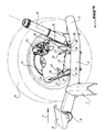
Figure 2, une roue 21 est montée rotative sur le support de roue 13 qui est ici représenté schématiquement par une plaque de fixation, cette plaque étant ici située dans le voisinage d'un étrier de frein 23.2, a
Le support de roue 13 est fixé au bras oscillant 4 par une liaison flexible. Cette liaison flexible permet au support de roue 13 de tourner autour d'un axe de rotation A4 distinct de l'axe de la roue A1. La liaison flexible est ici formée par deux plaques flexibles 25 et 26 qui sont contenues dans deux plans distincts dont l'intersection coïncide avec cet axe de rotation.The
Chaque plaque flexible 25, 26 a un premier bord 27, 28 rigidement fixé au bras oscillant 4 et un second bord 29, 30 qui est rigidement fixé au support de roue 13. Cette liaison flexible peut être dimensionnée spécifiquement pour obtenir une élasticité souhaitée de la liaison flexible, sans altérer les autres caractéristiques du train arrière.Each
Ces plaques flexibles 25, 26 sont inscrites dans deux plans distincts formant un certain angle l'un par rapport à l'autre de manière à définir un V ouvert vers le haut. L'orientation de ces plaques flexibles 25, 26 définit la position de l'axe A4, qui est l'intersection des plans dans lesquels sont contenues ces plaques flexibles.These
Dans la représentation symbolique de la figure 2, les bords 28 et 30 se suivent le long d'un même côté de la plaque flexible 26, mais dans les autres exemples de liaison détaillés plus bas, ces deux bords s'étendent sur des côtés opposés de la plaque flexible 26, ce qui donne lieu à une meilleure flexion de la plaque 26 lorsqu'elle est sollicitée mécaniquement.In the symbolic representation of FIG. 2, the
Il faut noter que la liaison flexible peut également être constituée de plus de deux plaques flexibles reliant le bras oscillant au support de roue et situées dans des plans distincts qui se coupent deux à deux en un même axe A4 unique.It should be noted that the flexible connection may also consist of more than two flexible plates connecting the oscillating arm to the wheel support and located in separate planes that intersect in pairs in the same single axis A4.
L'axe de rotation A4 du support de roue est situé sensiblement sous le sol, voire à hauteur du point de contact de la roue 21 avec le sol, en étant orienté transversalement, c'est-à-dire parallèlement à l'axe de rotation de la roue. La liaison permet ainsi un recul de la roue selon un mouvement sensiblement pendulaire, autour de l'axe A4, ce mouvement étant inscrit dans un plan vertical longitudinal par rapport au véhicule.The axis of rotation A4 of the wheel support is located substantially below the ground, or even at the point of contact of the
Le degré de liberté supplémentaire est donc ici une élasticité longitudinale permettant à la roue 21 de reculer le long du véhicule. Cette possibilité de recul facilite le passage d'obstacles de dits "francs" ou à "front raide", c'est-à-dire présentant un bord vertical ou sensiblement vertical avec lequel la roue entre en contact en premier. Lorsqu'un tel obstacle entre en contact avec la roue 21, il génère un effort de percussion sur cette roue, mais cet effort de percussion est atténué par le recul de la roue, ce qui améliore le confort du véhicule. Lorsque cet effort s'annule, la roue revient vers une position de référence, du fait de la flexibilité de la liaison.The additional degree of freedom is here a longitudinal elasticity allowing the
On notera que compte tenu de la position de l'axe A4 en base de roue, la liaison flexible a une raideur élevée en base de roue pour ne pas perturber le comportement routier du véhicule, notamment au freinage, et qu'elle a une raideur plus faible lorsqu'un effort est appliqué à hauteur du centre roue pour procurer l'élasticité longitudinale nécessaire au franchissement d'obstacles.Note that given the position of the axis A4 wheel base, the flexible connection has a high stiffness wheel base to not disturb the road behavior of the vehicle, including braking, and it has a stiffness weaker when a force is applied at the center of the wheel to provide the longitudinal elasticity necessary for the crossing of obstacles.
Selon l'invention, le train arrière est muni d'au moins un organe de butée qui agit sur la liaison flexible pour limiter le mouvement du support 13 par rapport au bras oscillant 4, afin de garantir la tenue mécanique de la liaison élastique lors du passage d'obstacles sévères du type pavé, saignée, etc.According to the invention, the rear axle is provided with at least one stop member which acts on the flexible link to limit the movement of the
Dans un premier mode de réalisation de l'invention qui est représenté sur la figure 3, un train arrière selon l'invention est équipé d'un organe de butée 31 qui limite le mouvement du support de roue 13. Dans l'exemple de la figure 3, l'organe de butée 31 est formé par une plaque sensiblement rectangulaire disposée dans un plan sensiblement horizontal par rapport à la plaque flexible 26.In a first embodiment of the invention shown in FIG. 3, a rear axle according to the invention is equipped with an
Cette plaque 31 a un premier bord 32 rigidement fixé au bras oscillant 4, et un second bord 33 adjacent et perpendiculaire au premier, qui est disposé en vis-à-vis de la plaque flexible 26 tout en étant légèrement espacé de celle-ci lorsque la liaison flexible est au repos, c'est-à-dire lorsque la plaque flexible 26 est dans un état non fléchi.This
Lorsqu'un effort important, tel que l'effort repéré par F sur la figure 3, est appliqué à la liaison flexible, la plaque flexible 26 fléchit jusqu'à venir en appui contre le bord 33 de la plaque 31, ce qui limite l'amplitude de flexion de cette plaque flexible 26 pour limiter par là même l'amplitude du mouvement du support 13 par rapport au bras oscillant 4.When a large force, such as the force indicated by F in FIG. 3, is applied to the flexible connection, the
Ainsi, lorsqu'un effort important est appliqué à la liaison flexible, la déformation de la plaque flexible 26 est limitée à l'écartement qui la sépare du bord 33, ce qui correspond à un domaine de déformation élastique de la plaque flexible. Après application de cet effort important, la liaison flexible revient dans sa position de référence.Thus, when a large force is applied to the flexible connection, the deformation of the
Cet organe de butée permet d'améliorer significativement la tenue mécanique de la liaison flexible. Il permet d'éviter une déformation trop importante de la plaque flexible qui pourrait conduire à une déformation permanente de celle-ci. Dans des cas plus critiques, il permet d'éviter une détérioration plus importante de la plaque flexible telle que son arrachement.This abutment member makes it possible to significantly improve the mechanical strength of the connection flexible. It avoids excessive deformation of the flexible plate which could lead to permanent deformation thereof. In more critical cases, it avoids further deterioration of the flexible plate such as tearing.
Lorsqu'un effort moins important est appliqué à la liaison flexible, la plaque flexible 26 se déforme sans atteindre le bord 33 de l'organe de butée 31, puis revient dans sa position de référence lorsque l'effort s'annule.When a smaller force is applied to the flexible connection, the
Dans l'exemple de la figure 3, la plaque de butée 31 est fixée au bras oscillant 4 pour limiter le mouvement de la plaque flexible 26. Mais cette plaque de butée peut également être fixée au support de roue 13 pour limiter de façon similaire le mouvement de la plaque flexible 26.In the example of FIG. 3, the
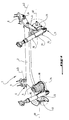
Un second mode de réalisation de l'invention est représenté sur les figures 4 et 5, dans lesquelles l'organe de butée qui limite le mouvement du support de roue comprend deux plaques fixes 35, 36 sensiblement rectangulaires et solidaires du bras oscillant, associées à deux arrêtoirs 42, 43 solidaires de la fusée 13.A second embodiment of the invention is shown in Figures 4 and 5, wherein the stop member which limits the movement of the wheel support comprises two fixed
Les deux plaques fixes ont chacune un premier bord fixe 37, 38 rigidement fixé au bras oscillant 4, et un second bord libre 39, 40, opposé au premier bord, qui s'étend parallèlement à la plaque constituant le support 13 sans être fixé à celle-ci.The two fixed plates each have a first fixed
Chaque plaque fixe 35, 36 s'étend parallèlement à une plaque flexible correspondante tout en étant légèrement espacée de cette plaque flexible correspondante le long du bras oscillant 4. Dans l'exemple des figures 4 et 5, les deux plaques fixes 35, 36 sont positionnées entre les deux plaques flexibles 25, 26 le long du bras oscillant 4.Each fixed
Les deux arrêtoirs 42, 43 qui sont rigidement fixés au support 13 sont disposés chacun en vis-à-vis d'une plaque fixe correspondante dans une région proche du bord libre de cette plaque fixe correspondante.The two
Comme visible figure 4, les deux plaques fixes 35 et 36, qui sont perpendiculaires au bras 4, sont reliées l'une à l'autre par un renfort 45 de forme sensiblement rectangulaire, qui s'étend parallèlement au bras oscillant 4 et qui a chacune de ses extrémités rigidement fixée au centre d'une plaque fixe 35, 36 correspondante.As can be seen in FIG. 4, the two fixed
Ainsi les deux plaques fixes 35, 36, avec le renfort 45 constituent une sorte de caisson rigidement solidaire du bras oscillant, et qui est positionné entre les deux plaques flexibles 25 et 26. Chaque plaque flexible est légèrement espacée de la plaque fixe correspondante, et les deux arrêtoirs 42, 43 sont situés entre les deux plaques fixes 35, 36 en étant eux-mêmes légèrement espacés des deux plaques rigides correspondantes.Thus the two fixed
Lors du franchissement d'un obstacle du type défini plus haut, un effort est appliqué à mi-hauteur de la roue, depuis l'avant vers l'arrière du véhicule, ce qui est représenté par la flèche F sur la figure 4. Dans ce cas, grâce à la flexibilité des plaques 25 et 26, le support 13 se déplace longitudinalement en direction de l'extrémité arrière 11 du bras oscillant pour absorber cet effort.When crossing an obstacle of the type defined above, a force is applied halfway up the wheel, from the front to the rear of the vehicle, which is represented by the arrow F in FIG. this case, thanks to the flexibility of the
Durant ce mouvement, la plaque flexible 25 se courbe de telle sorte qu'elle se rapproche de la plaque fixe 35, et la plaque flexible 26 se courbe de telle sorte qu'elle s'éloigne de la plaque fixe 36. Les plaques fixes 35, 36 restent dans la même position car elles sont solidaires seulement du bras oscillant 4.During this movement, the
Selon ce mouvement, l'arrêtoir 42 s'éloigne de la plaque fixe 35, et l'arrêtoir 43 se rapproche de la plaque fixe 36. Si l'effort F a une valeur trop importante, l'amplitude du mouvement est limitée par l'arrêtoir 43 qui vient en appui contre la plaque fixe 36.According to this movement, the
De manière analogue, lorsqu'un effort est appliqué à la roue en sens inverse, c'est-à-dire en étant dirigé depuis l'arrière vers l'avant du véhicule, c'est l'arrêtoir 42 qui vient en appui contre la plaque fixe 35 pour limiter l'amplitude du déplacement du support 13 par rapport au bras oscillant 4.Similarly, when a force is applied to the wheel in the opposite direction, that is to say, being directed from the rear to the front of the vehicle, it is the
Avantageusement, une entretoise non représentée, en matériau élastique tel que du caoutchouc, est intercalée dans l'espace qui sépare l'arrêtoir 42 de la plaque 35, et entre l'espace qui sépare l'arrêtoir 43 de la plaque 36. Ainsi, en cas d'effort F important, la limitation du mouvement du support 13 est alors réalisée de manière progressive par écrasement de l'entretoise en élastomère, ce qui évite notamment un choc entre l'arrêtoir et la plaque fixe correspondante et évite par là même de générer un bruit.Advantageously, a not shown spacer, of elastic material such as rubber, is interposed in the space between the
Avantageusement, le renfort 45 qui relie les deux plaques fixes est une partie de l'assise 15 qui reçoit une extrémité du ressort 17, de telle sorte que l'assise 15 constitue avec les plaques fixes 35, 36 un caisson dans lequel vient se positionner l'extrémité du ressort 17, comme représenté schématiquement sur la figure 5.Advantageously, the
Comme visible sur les figures 4 et 5, les plaques fixes 35, 36 sont avantageusement réalisées avec de la tôle de forte épaisseur, l'assise 15 qui inclut le renfort 45 pouvant quant à elle être fabriquée à partir d'une tôle de plus faible épaisseur par emboutissage ou par pliage.As can be seen in FIGS. 4 and 5, the fixed
Claims (8)
Applications Claiming Priority (1)
| Application Number | Priority Date | Filing Date | Title |
|---|---|---|---|
| FR0407374A FR2872453B1 (en) | 2004-07-02 | 2004-07-02 | MOTOR VEHICLE TRAIN WITH LONGITUDINAL ELASTICITY LIMITED BY A STOPPER MEMBER |
Publications (2)
| Publication Number | Publication Date |
|---|---|
| EP1612068A1 true EP1612068A1 (en) | 2006-01-04 |
| EP1612068B1 EP1612068B1 (en) | 2008-05-14 |
Family
ID=34947417
Family Applications (1)
| Application Number | Title | Priority Date | Filing Date |
|---|---|---|---|
| EP05300504A Not-in-force EP1612068B1 (en) | 2004-07-02 | 2005-06-22 | Vehicle axle with longitudinal elasticity limited by a stop device |
Country Status (6)
| Country | Link |
|---|---|
| EP (1) | EP1612068B1 (en) |
| AT (1) | ATE395203T1 (en) |
| DE (1) | DE602005006670D1 (en) |
| ES (1) | ES2307132T3 (en) |
| FR (1) | FR2872453B1 (en) |
| PT (1) | PT1612068E (en) |
Cited By (10)
| Publication number | Priority date | Publication date | Assignee | Title |
|---|---|---|---|---|
| FR2902698A1 (en) * | 2006-06-23 | 2007-12-28 | Michelin Soc Tech | Suspended rear axle for e.g. passenger car, has crossbeam including ends that are connected to respective longitudinal arms for forming rigid parts, and chuck stop limiting wheel`s steering movement towards interior of vehicle |
| FR2909310A1 (en) * | 2006-12-05 | 2008-06-06 | Peugeot Citroen Automobiles Sa | Motor vehicle's rear axle, has connection units intercalated between rigid and stub axles, and permitting rotation of stub axle around rotation axis distinct from stub axle axis, where units have plates inclined with respect to each other |
| FR2926248A1 (en) * | 2008-01-16 | 2009-07-17 | Peugeot Citroen Automobiles Sa | Undercarriage sub-assembly for motor vehicle, has connection device interposed between steering axle swivel and arms, where connection device is deformed such that lateral or longitudinal effort applied to vehicle provokes braking of swivel |
| DE102008001030A1 (en) * | 2008-04-07 | 2009-10-08 | Bayerische Motoren Werke Aktiengesellschaft | Countersteering vehicle rear axle |
| DE102008031123A1 (en) * | 2008-07-02 | 2010-01-07 | Bayerische Motoren Werke Aktiengesellschaft | Countersteering vehicle rear axle |
| WO2010034807A1 (en) * | 2008-09-26 | 2010-04-01 | M.B. Gerrard V/Miles B. Gerrard | A vehicle suspension |
| FR2991918A1 (en) * | 2012-06-18 | 2013-12-20 | Peugeot Citroen Automobiles Sa | Flexible suspension blade for rear wheel-axle of car, has central part intended to be fixed to body of car, where ends of blade include cut portions that are folded to provide connection system with hub carrier |
| EP2952361A1 (en) * | 2014-06-05 | 2015-12-09 | Benteler Automobiltechnik GmbH | Constructed wheel support |
| WO2016182501A1 (en) * | 2015-05-13 | 2016-11-17 | China-Euro Vehicle Technology Aktiebolag | Wheel carrier |
| US10808792B2 (en) | 2018-07-18 | 2020-10-20 | Honda Motor Co, Ltd. | Apparatus for shielding vehicle component |
Citations (6)
| Publication number | Priority date | Publication date | Assignee | Title |
|---|---|---|---|---|
| US1890766A (en) * | 1929-01-31 | 1932-12-13 | Adams Frank John | Mounting the steered wheels of road vehicles |
| FR1096872A (en) * | 1953-11-24 | 1955-06-27 | Mft Fr Pneumatiques Michelin | Vehicle suspension responsive to horizontal forces |
| US20030038441A1 (en) * | 2001-08-23 | 2003-02-27 | Joachim Fornbacher | Wheel suspension of a motor vehicle |
| EP1288028A2 (en) | 2001-09-03 | 2003-03-05 | Sistemi Sospensioni S.p.A. | A wheel suspension arm and a motor-vehicle independent suspension system comprising the arm |
| EP1361084A2 (en) * | 2002-05-10 | 2003-11-12 | Sistemi Sospensioni S.p.A. | Mounting structure for a wheel carrier of a motor vehicle |
| FR2861333A1 (en) * | 2003-10-28 | 2005-04-29 | Peugeot Citroen Automobiles Sa | Rear end for motor vehicle, has steering knuckle fixed to swing arm by flexible link that allows rotation of knuckle around rotation axis that is distinct from axis of wheel and is situated below ground |
-
2004
- 2004-07-02 FR FR0407374A patent/FR2872453B1/en not_active Expired - Fee Related
-
2005
- 2005-06-22 ES ES05300504T patent/ES2307132T3/en active Active
- 2005-06-22 EP EP05300504A patent/EP1612068B1/en not_active Not-in-force
- 2005-06-22 AT AT05300504T patent/ATE395203T1/en not_active IP Right Cessation
- 2005-06-22 DE DE602005006670T patent/DE602005006670D1/en active Active
- 2005-06-22 PT PT05300504T patent/PT1612068E/en unknown
Patent Citations (6)
| Publication number | Priority date | Publication date | Assignee | Title |
|---|---|---|---|---|
| US1890766A (en) * | 1929-01-31 | 1932-12-13 | Adams Frank John | Mounting the steered wheels of road vehicles |
| FR1096872A (en) * | 1953-11-24 | 1955-06-27 | Mft Fr Pneumatiques Michelin | Vehicle suspension responsive to horizontal forces |
| US20030038441A1 (en) * | 2001-08-23 | 2003-02-27 | Joachim Fornbacher | Wheel suspension of a motor vehicle |
| EP1288028A2 (en) | 2001-09-03 | 2003-03-05 | Sistemi Sospensioni S.p.A. | A wheel suspension arm and a motor-vehicle independent suspension system comprising the arm |
| EP1361084A2 (en) * | 2002-05-10 | 2003-11-12 | Sistemi Sospensioni S.p.A. | Mounting structure for a wheel carrier of a motor vehicle |
| FR2861333A1 (en) * | 2003-10-28 | 2005-04-29 | Peugeot Citroen Automobiles Sa | Rear end for motor vehicle, has steering knuckle fixed to swing arm by flexible link that allows rotation of knuckle around rotation axis that is distinct from axis of wheel and is situated below ground |
Cited By (15)
| Publication number | Priority date | Publication date | Assignee | Title |
|---|---|---|---|---|
| FR2902698A1 (en) * | 2006-06-23 | 2007-12-28 | Michelin Soc Tech | Suspended rear axle for e.g. passenger car, has crossbeam including ends that are connected to respective longitudinal arms for forming rigid parts, and chuck stop limiting wheel`s steering movement towards interior of vehicle |
| FR2909310A1 (en) * | 2006-12-05 | 2008-06-06 | Peugeot Citroen Automobiles Sa | Motor vehicle's rear axle, has connection units intercalated between rigid and stub axles, and permitting rotation of stub axle around rotation axis distinct from stub axle axis, where units have plates inclined with respect to each other |
| FR2926248A1 (en) * | 2008-01-16 | 2009-07-17 | Peugeot Citroen Automobiles Sa | Undercarriage sub-assembly for motor vehicle, has connection device interposed between steering axle swivel and arms, where connection device is deformed such that lateral or longitudinal effort applied to vehicle provokes braking of swivel |
| US7914019B2 (en) | 2008-04-07 | 2011-03-29 | Bayerische Motoren Werke Aktiengesellschaft | Countersteering rear vehicle axle |
| DE102008001030A1 (en) * | 2008-04-07 | 2009-10-08 | Bayerische Motoren Werke Aktiengesellschaft | Countersteering vehicle rear axle |
| DE102008031123A1 (en) * | 2008-07-02 | 2010-01-07 | Bayerische Motoren Werke Aktiengesellschaft | Countersteering vehicle rear axle |
| US8220810B2 (en) | 2008-07-02 | 2012-07-17 | Bayerische Motoren Werke Aktiengesellschaft | Countersteering rear axle of a vehicle |
| WO2010034807A1 (en) * | 2008-09-26 | 2010-04-01 | M.B. Gerrard V/Miles B. Gerrard | A vehicle suspension |
| US8342547B2 (en) | 2008-09-26 | 2013-01-01 | M. B. Gerrard V/Miles B. Gerrard | Vehicle suspension |
| FR2991918A1 (en) * | 2012-06-18 | 2013-12-20 | Peugeot Citroen Automobiles Sa | Flexible suspension blade for rear wheel-axle of car, has central part intended to be fixed to body of car, where ends of blade include cut portions that are folded to provide connection system with hub carrier |
| EP2952361A1 (en) * | 2014-06-05 | 2015-12-09 | Benteler Automobiltechnik GmbH | Constructed wheel support |
| US9555682B2 (en) | 2014-06-05 | 2017-01-31 | Benteler Automobiltechnik Gmbh | Constructed wheel support |
| WO2016182501A1 (en) * | 2015-05-13 | 2016-11-17 | China-Euro Vehicle Technology Aktiebolag | Wheel carrier |
| US9682606B2 (en) | 2015-05-13 | 2017-06-20 | China-Euro Vehicle Technology Aktiebolag | Wheel carrier |
| US10808792B2 (en) | 2018-07-18 | 2020-10-20 | Honda Motor Co, Ltd. | Apparatus for shielding vehicle component |
Also Published As
| Publication number | Publication date |
|---|---|
| FR2872453B1 (en) | 2006-11-17 |
| EP1612068B1 (en) | 2008-05-14 |
| PT1612068E (en) | 2008-08-25 |
| ATE395203T1 (en) | 2008-05-15 |
| ES2307132T3 (en) | 2008-11-16 |
| FR2872453A1 (en) | 2006-01-06 |
| DE602005006670D1 (en) | 2008-06-26 |
Similar Documents
| Publication | Publication Date | Title |
|---|---|---|
| EP1612068B1 (en) | Vehicle axle with longitudinal elasticity limited by a stop device | |
| EP2072850B1 (en) | System for installing a disc brake shoe | |
| EP1883574B1 (en) | Rear fork for bicycle | |
| EP3299248B1 (en) | An obstacle detection device, for a railway vehicle | |
| EP3061696B1 (en) | Blank for forming a packaging of at least one windscreen wiper, packaging and method of producing such a packaging | |
| EP1527911B1 (en) | Semi-deformable rear suspension with longitudinal flexibility | |
| EP1742826B1 (en) | Front structure of a motor vehicle | |
| EP1640249B1 (en) | Motor vehicle with a twist beam axle with a longitudinally movable stub axle | |
| WO2011023871A1 (en) | Vehicle comprising a shock-absorbing spring assembly | |
| WO2007006996A2 (en) | Motor vehicle front spoiler with deformable sealing bulkhead | |
| EP3222486B1 (en) | Railway vehicle bogie comprising a lowered body | |
| FR2729980A1 (en) | ROAD SAFETY SLIDE WITH SHOCK ABSORBING DEVICE | |
| EP1742818B1 (en) | Deformation box for a motor vehicle | |
| EP2881303A1 (en) | Shock absorber for coupling railway wagons | |
| FR2772710A1 (en) | TRACTION VEHICLE, ESPECIALLY TRACTION VEHICLE INTENDED FOR VERY HIGH SPEED TRAINS | |
| EP0007820B1 (en) | Improvement in the suspension of a vehicle wheel train | |
| FR2812242A1 (en) | Automobile deformable axle comprises pair of longitudinal suspension arms connected by torsion deformable crosspiece, one end of each arm connected to bodywork by elastic articulation and one end to wheel hub | |
| EP2868519B1 (en) | Stowable anti-spill seat | |
| EP3027442B1 (en) | Drive train for a motor vehicle | |
| EP0253708B1 (en) | Rear wheel suspension system with passive action for motor vehicle, and motor vehicle equipped with such suspension system | |
| FR2832098A1 (en) | Multi-arm rear wheel axle unit comprises, for each wheel, rear and front transverse arms pivoted by elastic connections to chassis and to wheel pivot and suspension leaf spring | |
| FR2934813A1 (en) | Axle i.e. semi-rigid rear axle, for front drive wheel vehicle, has connection piece whose parts are connected between each other by sliding connection that authorizes displacement of support with respect to axle along axis of vehicle | |
| WO2022234213A1 (en) | Vehicle seat having a backrest equipped with shock absorbing means | |
| EP2322406B1 (en) | Simplified device for locking in position an adjustable steering column of a vehicle | |
| EP0289397A1 (en) | Bumper for motor vehicle and vehicle equipped with such a bumper |
Legal Events
| Date | Code | Title | Description |
|---|---|---|---|
| PUAI | Public reference made under article 153(3) epc to a published international application that has entered the european phase |
Free format text: ORIGINAL CODE: 0009012 |
|
| AK | Designated contracting states |
Kind code of ref document: A1 Designated state(s): AT BE BG CH CY CZ DE DK EE ES FI FR GB GR HU IE IS IT LI LT LU MC NL PL PT RO SE SI SK TR |
|
| AX | Request for extension of the european patent |
Extension state: AL BA HR LV MK YU |
|
| RIN1 | Information on inventor provided before grant (corrected) |
Inventor name: TOUPET, SEBASTIEN |
|
| 17P | Request for examination filed |
Effective date: 20060123 |
|
| AKX | Designation fees paid |
Designated state(s): AT BE BG CH CY CZ DE DK EE ES FI FR GB GR HU IE IS IT LI LT LU MC NL PL PT RO SE SI SK TR |
|
| 17Q | First examination report despatched |
Effective date: 20061219 |
|
| GRAP | Despatch of communication of intention to grant a patent |
Free format text: ORIGINAL CODE: EPIDOSNIGR1 |
|
| GRAS | Grant fee paid |
Free format text: ORIGINAL CODE: EPIDOSNIGR3 |
|
| GRAA | (expected) grant |
Free format text: ORIGINAL CODE: 0009210 |
|
| AK | Designated contracting states |
Kind code of ref document: B1 Designated state(s): AT BE BG CH CY CZ DE DK EE ES FI FR GB GR HU IE IS IT LI LT LU MC NL PL PT RO SE SI SK TR |
|
| REG | Reference to a national code |
Ref country code: GB Ref legal event code: FG4D Free format text: NOT ENGLISH |
|
| REG | Reference to a national code |
Ref country code: CH Ref legal event code: EP |
|
| REG | Reference to a national code |
Ref country code: IE Ref legal event code: FG4D |
|
| REF | Corresponds to: |
Ref document number: 602005006670 Country of ref document: DE Date of ref document: 20080626 Kind code of ref document: P |
|
| REG | Reference to a national code |
Ref country code: PT Ref legal event code: SC4A Free format text: AVAILABILITY OF NATIONAL TRANSLATION Effective date: 20080812 |
|
| PG25 | Lapsed in a contracting state [announced via postgrant information from national office to epo] |
Ref country code: SI Free format text: LAPSE BECAUSE OF FAILURE TO SUBMIT A TRANSLATION OF THE DESCRIPTION OR TO PAY THE FEE WITHIN THE PRESCRIBED TIME-LIMIT Effective date: 20080514 |
|
| PG25 | Lapsed in a contracting state [announced via postgrant information from national office to epo] |
Ref country code: FI Free format text: LAPSE BECAUSE OF FAILURE TO SUBMIT A TRANSLATION OF THE DESCRIPTION OR TO PAY THE FEE WITHIN THE PRESCRIBED TIME-LIMIT Effective date: 20080514 |
|
| NLV1 | Nl: lapsed or annulled due to failure to fulfill the requirements of art. 29p and 29m of the patents act | ||
| REG | Reference to a national code |
Ref country code: ES Ref legal event code: FG2A Ref document number: 2307132 Country of ref document: ES Kind code of ref document: T3 |
|
| PG25 | Lapsed in a contracting state [announced via postgrant information from national office to epo] |
Ref country code: AT Free format text: LAPSE BECAUSE OF FAILURE TO SUBMIT A TRANSLATION OF THE DESCRIPTION OR TO PAY THE FEE WITHIN THE PRESCRIBED TIME-LIMIT Effective date: 20080514 Ref country code: PL Free format text: LAPSE BECAUSE OF FAILURE TO SUBMIT A TRANSLATION OF THE DESCRIPTION OR TO PAY THE FEE WITHIN THE PRESCRIBED TIME-LIMIT Effective date: 20080514 Ref country code: NL Free format text: LAPSE BECAUSE OF FAILURE TO SUBMIT A TRANSLATION OF THE DESCRIPTION OR TO PAY THE FEE WITHIN THE PRESCRIBED TIME-LIMIT Effective date: 20080514 |
|
| BERE | Be: lapsed |
Owner name: PEUGEOT CITROEN AUTOMOBILES SA Effective date: 20080630 |
|
| PG25 | Lapsed in a contracting state [announced via postgrant information from national office to epo] |
Ref country code: IS Free format text: LAPSE BECAUSE OF FAILURE TO SUBMIT A TRANSLATION OF THE DESCRIPTION OR TO PAY THE FEE WITHIN THE PRESCRIBED TIME-LIMIT Effective date: 20080914 |
|
| REG | Reference to a national code |
Ref country code: IE Ref legal event code: FD4D |
|
| REG | Reference to a national code |
Ref country code: GB Ref legal event code: 746 Effective date: 20081222 |
|
| PG25 | Lapsed in a contracting state [announced via postgrant information from national office to epo] |
Ref country code: MC Free format text: LAPSE BECAUSE OF NON-PAYMENT OF DUE FEES Effective date: 20080630 Ref country code: LT Free format text: LAPSE BECAUSE OF FAILURE TO SUBMIT A TRANSLATION OF THE DESCRIPTION OR TO PAY THE FEE WITHIN THE PRESCRIBED TIME-LIMIT Effective date: 20080514 Ref country code: SE Free format text: LAPSE BECAUSE OF FAILURE TO SUBMIT A TRANSLATION OF THE DESCRIPTION OR TO PAY THE FEE WITHIN THE PRESCRIBED TIME-LIMIT Effective date: 20080814 Ref country code: CZ Free format text: LAPSE BECAUSE OF FAILURE TO SUBMIT A TRANSLATION OF THE DESCRIPTION OR TO PAY THE FEE WITHIN THE PRESCRIBED TIME-LIMIT Effective date: 20080514 Ref country code: IE Free format text: LAPSE BECAUSE OF FAILURE TO SUBMIT A TRANSLATION OF THE DESCRIPTION OR TO PAY THE FEE WITHIN THE PRESCRIBED TIME-LIMIT Effective date: 20080514 Ref country code: DK Free format text: LAPSE BECAUSE OF FAILURE TO SUBMIT A TRANSLATION OF THE DESCRIPTION OR TO PAY THE FEE WITHIN THE PRESCRIBED TIME-LIMIT Effective date: 20080514 |
|
| PG25 | Lapsed in a contracting state [announced via postgrant information from national office to epo] |
Ref country code: RO Free format text: LAPSE BECAUSE OF FAILURE TO SUBMIT A TRANSLATION OF THE DESCRIPTION OR TO PAY THE FEE WITHIN THE PRESCRIBED TIME-LIMIT Effective date: 20080514 |
|
| PLBE | No opposition filed within time limit |
Free format text: ORIGINAL CODE: 0009261 |
|
| STAA | Information on the status of an ep patent application or granted ep patent |
Free format text: STATUS: NO OPPOSITION FILED WITHIN TIME LIMIT |
|
| PG25 | Lapsed in a contracting state [announced via postgrant information from national office to epo] |
Ref country code: BE Free format text: LAPSE BECAUSE OF NON-PAYMENT OF DUE FEES Effective date: 20080630 |
|
| 26N | No opposition filed |
Effective date: 20090217 |
|
| PG25 | Lapsed in a contracting state [announced via postgrant information from national office to epo] |
Ref country code: EE Free format text: LAPSE BECAUSE OF FAILURE TO SUBMIT A TRANSLATION OF THE DESCRIPTION OR TO PAY THE FEE WITHIN THE PRESCRIBED TIME-LIMIT Effective date: 20080514 Ref country code: BG Free format text: LAPSE BECAUSE OF FAILURE TO SUBMIT A TRANSLATION OF THE DESCRIPTION OR TO PAY THE FEE WITHIN THE PRESCRIBED TIME-LIMIT Effective date: 20080814 |
|
| REG | Reference to a national code |
Ref country code: CH Ref legal event code: PL |
|
| PG25 | Lapsed in a contracting state [announced via postgrant information from national office to epo] |
Ref country code: LI Free format text: LAPSE BECAUSE OF NON-PAYMENT OF DUE FEES Effective date: 20090630 Ref country code: CH Free format text: LAPSE BECAUSE OF NON-PAYMENT OF DUE FEES Effective date: 20090630 |
|
| PG25 | Lapsed in a contracting state [announced via postgrant information from national office to epo] |
Ref country code: LU Free format text: LAPSE BECAUSE OF NON-PAYMENT OF DUE FEES Effective date: 20080622 Ref country code: CY Free format text: LAPSE BECAUSE OF FAILURE TO SUBMIT A TRANSLATION OF THE DESCRIPTION OR TO PAY THE FEE WITHIN THE PRESCRIBED TIME-LIMIT Effective date: 20080514 Ref country code: HU Free format text: LAPSE BECAUSE OF FAILURE TO SUBMIT A TRANSLATION OF THE DESCRIPTION OR TO PAY THE FEE WITHIN THE PRESCRIBED TIME-LIMIT Effective date: 20081115 |
|
| PG25 | Lapsed in a contracting state [announced via postgrant information from national office to epo] |
Ref country code: TR Free format text: LAPSE BECAUSE OF FAILURE TO SUBMIT A TRANSLATION OF THE DESCRIPTION OR TO PAY THE FEE WITHIN THE PRESCRIBED TIME-LIMIT Effective date: 20080514 |
|
| PG25 | Lapsed in a contracting state [announced via postgrant information from national office to epo] |
Ref country code: GR Free format text: LAPSE BECAUSE OF FAILURE TO SUBMIT A TRANSLATION OF THE DESCRIPTION OR TO PAY THE FEE WITHIN THE PRESCRIBED TIME-LIMIT Effective date: 20080815 |
|
| REG | Reference to a national code |
Ref country code: ES Ref legal event code: GC2A Effective date: 20110412 |
|
| PGFP | Annual fee paid to national office [announced via postgrant information from national office to epo] |
Ref country code: ES Payment date: 20120523 Year of fee payment: 8 |
|
| PGFP | Annual fee paid to national office [announced via postgrant information from national office to epo] |
Ref country code: SK Payment date: 20130529 Year of fee payment: 9 Ref country code: GB Payment date: 20130527 Year of fee payment: 9 Ref country code: DE Payment date: 20130523 Year of fee payment: 9 |
|
| PGFP | Annual fee paid to national office [announced via postgrant information from national office to epo] |
Ref country code: IT Payment date: 20130523 Year of fee payment: 9 Ref country code: PT Payment date: 20130619 Year of fee payment: 9 |
|
| PGFP | Annual fee paid to national office [announced via postgrant information from national office to epo] |
Ref country code: FR Payment date: 20130724 Year of fee payment: 9 |
|
| REG | Reference to a national code |
Ref country code: DE Ref legal event code: R119 Ref document number: 602005006670 Country of ref document: DE |
|
| REG | Reference to a national code |
Ref country code: PT Ref legal event code: MM4A Free format text: LAPSE DUE TO NON-PAYMENT OF FEES Effective date: 20141222 |
|
| PG25 | Lapsed in a contracting state [announced via postgrant information from national office to epo] |
Ref country code: PT Free format text: LAPSE BECAUSE OF NON-PAYMENT OF DUE FEES Effective date: 20141222 |
|
| GBPC | Gb: european patent ceased through non-payment of renewal fee |
Effective date: 20140622 |
|
| REG | Reference to a national code |
Ref country code: SK Ref legal event code: MM4A Ref document number: E 3810 Country of ref document: SK Effective date: 20140622 |
|
| REG | Reference to a national code |
Ref country code: FR Ref legal event code: ST Effective date: 20150227 |
|
| REG | Reference to a national code |
Ref country code: DE Ref legal event code: R119 Ref document number: 602005006670 Country of ref document: DE Effective date: 20150101 |
|
| PG25 | Lapsed in a contracting state [announced via postgrant information from national office to epo] |
Ref country code: SK Free format text: LAPSE BECAUSE OF NON-PAYMENT OF DUE FEES Effective date: 20140622 Ref country code: DE Free format text: LAPSE BECAUSE OF NON-PAYMENT OF DUE FEES Effective date: 20150101 Ref country code: IT Free format text: LAPSE BECAUSE OF NON-PAYMENT OF DUE FEES Effective date: 20140622 |
|
| PG25 | Lapsed in a contracting state [announced via postgrant information from national office to epo] |
Ref country code: GB Free format text: LAPSE BECAUSE OF NON-PAYMENT OF DUE FEES Effective date: 20140622 Ref country code: FR Free format text: LAPSE BECAUSE OF NON-PAYMENT OF DUE FEES Effective date: 20140630 |
|
| REG | Reference to a national code |
Ref country code: ES Ref legal event code: FD2A Effective date: 20150724 |
|
| PG25 | Lapsed in a contracting state [announced via postgrant information from national office to epo] |
Ref country code: ES Free format text: LAPSE BECAUSE OF NON-PAYMENT OF DUE FEES Effective date: 20140623 |