EP1611358B1 - Stetig verstellbares wegeventil - Google Patents
Stetig verstellbares wegeventil Download PDFInfo
- Publication number
- EP1611358B1 EP1611358B1 EP04725668A EP04725668A EP1611358B1 EP 1611358 B1 EP1611358 B1 EP 1611358B1 EP 04725668 A EP04725668 A EP 04725668A EP 04725668 A EP04725668 A EP 04725668A EP 1611358 B1 EP1611358 B1 EP 1611358B1
- Authority
- EP
- European Patent Office
- Prior art keywords
- valve
- seat
- seat slide
- pilot control
- control valve
- Prior art date
- Legal status (The legal status is an assumption and is not a legal conclusion. Google has not performed a legal analysis and makes no representation as to the accuracy of the status listed.)
- Expired - Lifetime
Links
- 230000000903 blocking effect Effects 0.000 claims 2
- 210000000078 claw Anatomy 0.000 description 10
- 238000006073 displacement reaction Methods 0.000 description 9
- 230000002093 peripheral effect Effects 0.000 description 2
- 230000006978 adaptation Effects 0.000 description 1
- 230000004888 barrier function Effects 0.000 description 1
- 230000001419 dependent effect Effects 0.000 description 1
- 238000011161 development Methods 0.000 description 1
- 230000018109 developmental process Effects 0.000 description 1
- 238000005553 drilling Methods 0.000 description 1
- 230000000694 effects Effects 0.000 description 1
- 238000005259 measurement Methods 0.000 description 1
- 238000000034 method Methods 0.000 description 1
- 230000000717 retained effect Effects 0.000 description 1
- 239000002699 waste material Substances 0.000 description 1
Images


Classifications
-
- F—MECHANICAL ENGINEERING; LIGHTING; HEATING; WEAPONS; BLASTING
- F15—FLUID-PRESSURE ACTUATORS; HYDRAULICS OR PNEUMATICS IN GENERAL
- F15B—SYSTEMS ACTING BY MEANS OF FLUIDS IN GENERAL; FLUID-PRESSURE ACTUATORS, e.g. SERVOMOTORS; DETAILS OF FLUID-PRESSURE SYSTEMS, NOT OTHERWISE PROVIDED FOR
- F15B13/00—Details of servomotor systems ; Valves for servomotor systems
- F15B13/01—Locking-valves or other detent i.e. load-holding devices
-
- F—MECHANICAL ENGINEERING; LIGHTING; HEATING; WEAPONS; BLASTING
- F16—ENGINEERING ELEMENTS AND UNITS; GENERAL MEASURES FOR PRODUCING AND MAINTAINING EFFECTIVE FUNCTIONING OF MACHINES OR INSTALLATIONS; THERMAL INSULATION IN GENERAL
- F16K—VALVES; TAPS; COCKS; ACTUATING-FLOATS; DEVICES FOR VENTING OR AERATING
- F16K31/00—Actuating devices; Operating means; Releasing devices
- F16K31/12—Actuating devices; Operating means; Releasing devices actuated by fluid
- F16K31/36—Actuating devices; Operating means; Releasing devices actuated by fluid in which fluid from the circuit is constantly supplied to the fluid motor
- F16K31/40—Actuating devices; Operating means; Releasing devices actuated by fluid in which fluid from the circuit is constantly supplied to the fluid motor with electrically-actuated member in the discharge of the motor
- F16K31/406—Actuating devices; Operating means; Releasing devices actuated by fluid in which fluid from the circuit is constantly supplied to the fluid motor with electrically-actuated member in the discharge of the motor acting on a piston
- F16K31/408—Actuating devices; Operating means; Releasing devices actuated by fluid in which fluid from the circuit is constantly supplied to the fluid motor with electrically-actuated member in the discharge of the motor acting on a piston the discharge being effected through the piston and being blockable by an electrically-actuated member making contact with the piston
-
- F—MECHANICAL ENGINEERING; LIGHTING; HEATING; WEAPONS; BLASTING
- F15—FLUID-PRESSURE ACTUATORS; HYDRAULICS OR PNEUMATICS IN GENERAL
- F15B—SYSTEMS ACTING BY MEANS OF FLUIDS IN GENERAL; FLUID-PRESSURE ACTUATORS, e.g. SERVOMOTORS; DETAILS OF FLUID-PRESSURE SYSTEMS, NOT OTHERWISE PROVIDED FOR
- F15B13/00—Details of servomotor systems ; Valves for servomotor systems
- F15B13/01—Locking-valves or other detent i.e. load-holding devices
- F15B13/015—Locking-valves or other detent i.e. load-holding devices using an enclosed pilot flow valve
-
- F—MECHANICAL ENGINEERING; LIGHTING; HEATING; WEAPONS; BLASTING
- F15—FLUID-PRESSURE ACTUATORS; HYDRAULICS OR PNEUMATICS IN GENERAL
- F15B—SYSTEMS ACTING BY MEANS OF FLUIDS IN GENERAL; FLUID-PRESSURE ACTUATORS, e.g. SERVOMOTORS; DETAILS OF FLUID-PRESSURE SYSTEMS, NOT OTHERWISE PROVIDED FOR
- F15B13/00—Details of servomotor systems ; Valves for servomotor systems
- F15B13/02—Fluid distribution or supply devices characterised by their adaptation to the control of servomotors
- F15B13/04—Fluid distribution or supply devices characterised by their adaptation to the control of servomotors for use with a single servomotor
- F15B13/042—Fluid distribution or supply devices characterised by their adaptation to the control of servomotors for use with a single servomotor operated by fluid pressure
- F15B13/043—Fluid distribution or supply devices characterised by their adaptation to the control of servomotors for use with a single servomotor operated by fluid pressure with electrically-controlled pilot valves
-
- F—MECHANICAL ENGINEERING; LIGHTING; HEATING; WEAPONS; BLASTING
- F16—ENGINEERING ELEMENTS AND UNITS; GENERAL MEASURES FOR PRODUCING AND MAINTAINING EFFECTIVE FUNCTIONING OF MACHINES OR INSTALLATIONS; THERMAL INSULATION IN GENERAL
- F16K—VALVES; TAPS; COCKS; ACTUATING-FLOATS; DEVICES FOR VENTING OR AERATING
- F16K11/00—Multiple-way valves, e.g. mixing valves; Pipe fittings incorporating such valves
- F16K11/02—Multiple-way valves, e.g. mixing valves; Pipe fittings incorporating such valves with all movable sealing faces moving as one unit
- F16K11/06—Multiple-way valves, e.g. mixing valves; Pipe fittings incorporating such valves with all movable sealing faces moving as one unit comprising only sliding valves, i.e. sliding closure elements
- F16K11/065—Multiple-way valves, e.g. mixing valves; Pipe fittings incorporating such valves with all movable sealing faces moving as one unit comprising only sliding valves, i.e. sliding closure elements with linearly sliding closure members
- F16K11/07—Multiple-way valves, e.g. mixing valves; Pipe fittings incorporating such valves with all movable sealing faces moving as one unit comprising only sliding valves, i.e. sliding closure elements with linearly sliding closure members with cylindrical slides
- F16K11/0716—Multiple-way valves, e.g. mixing valves; Pipe fittings incorporating such valves with all movable sealing faces moving as one unit comprising only sliding valves, i.e. sliding closure elements with linearly sliding closure members with cylindrical slides with fluid passages through the valve member
-
- F—MECHANICAL ENGINEERING; LIGHTING; HEATING; WEAPONS; BLASTING
- F16—ENGINEERING ELEMENTS AND UNITS; GENERAL MEASURES FOR PRODUCING AND MAINTAINING EFFECTIVE FUNCTIONING OF MACHINES OR INSTALLATIONS; THERMAL INSULATION IN GENERAL
- F16K—VALVES; TAPS; COCKS; ACTUATING-FLOATS; DEVICES FOR VENTING OR AERATING
- F16K31/00—Actuating devices; Operating means; Releasing devices
- F16K31/12—Actuating devices; Operating means; Releasing devices actuated by fluid
- F16K31/36—Actuating devices; Operating means; Releasing devices actuated by fluid in which fluid from the circuit is constantly supplied to the fluid motor
- F16K31/40—Actuating devices; Operating means; Releasing devices actuated by fluid in which fluid from the circuit is constantly supplied to the fluid motor with electrically-actuated member in the discharge of the motor
-
- Y—GENERAL TAGGING OF NEW TECHNOLOGICAL DEVELOPMENTS; GENERAL TAGGING OF CROSS-SECTIONAL TECHNOLOGIES SPANNING OVER SEVERAL SECTIONS OF THE IPC; TECHNICAL SUBJECTS COVERED BY FORMER USPC CROSS-REFERENCE ART COLLECTIONS [XRACs] AND DIGESTS
- Y10—TECHNICAL SUBJECTS COVERED BY FORMER USPC
- Y10T—TECHNICAL SUBJECTS COVERED BY FORMER US CLASSIFICATION
- Y10T137/00—Fluid handling
- Y10T137/8593—Systems
- Y10T137/86928—Sequentially progressive opening or closing of plural valves
- Y10T137/86936—Pressure equalizing or auxiliary shunt flow
- Y10T137/86944—One valve seats against other valve [e.g., concentric valves]
- Y10T137/86968—With balancing chamber
-
- Y—GENERAL TAGGING OF NEW TECHNOLOGICAL DEVELOPMENTS; GENERAL TAGGING OF CROSS-SECTIONAL TECHNOLOGIES SPANNING OVER SEVERAL SECTIONS OF THE IPC; TECHNICAL SUBJECTS COVERED BY FORMER USPC CROSS-REFERENCE ART COLLECTIONS [XRACs] AND DIGESTS
- Y10—TECHNICAL SUBJECTS COVERED BY FORMER USPC
- Y10T—TECHNICAL SUBJECTS COVERED BY FORMER US CLASSIFICATION
- Y10T137/00—Fluid handling
- Y10T137/8593—Systems
- Y10T137/86928—Sequentially progressive opening or closing of plural valves
- Y10T137/87016—Lost motion
-
- Y—GENERAL TAGGING OF NEW TECHNOLOGICAL DEVELOPMENTS; GENERAL TAGGING OF CROSS-SECTIONAL TECHNOLOGIES SPANNING OVER SEVERAL SECTIONS OF THE IPC; TECHNICAL SUBJECTS COVERED BY FORMER USPC CROSS-REFERENCE ART COLLECTIONS [XRACs] AND DIGESTS
- Y10—TECHNICAL SUBJECTS COVERED BY FORMER USPC
- Y10T—TECHNICAL SUBJECTS COVERED BY FORMER US CLASSIFICATION
- Y10T137/00—Fluid handling
- Y10T137/8593—Systems
- Y10T137/87169—Supply and exhaust
- Y10T137/87193—Pilot-actuated
- Y10T137/87209—Electric
Definitions
- the invention relates to a continuously adjustable directional control valve according to the preamble of claim 1.
- Such proportionally adjustable directional control valves can be used, for example, as pilot valves for pilot control of main valve stages or else as a self-sufficient control element in hydraulic drives. There is the requirement that the pressure lines to the consumer are shut off leak-free. This freedom from leakage makes it possible to hold a load in a predetermined relative position to a working machine. Leakage freedom can not be guaranteed with a proportional valve alone, since a leakage flow over the circumferential surfaces of the valve slide can not be excluded.
- a leak-free clamping of the consumer is required, for example, in pipe laying work with an excavator, in which the boom of the excavator positioned a piece of pipe and held in position until it is welded. In case of leakage, this relative position would change to the already laid pipe section.
- a load-holding valve is provided for leak-free shut-off between the consumer and a proportionally adjustable directional control valve.
- a continuously adjustable directional control valve with an inlet channel, a consumer channel and a drain channel, wherein the connection between the channels via a valve spool on or is zuu Kunststoffbar.
- a check valve is arranged, the valve cone is biased against a valve seat.
- a pilot valve body is biased against a pilot valve seat.
- the present invention seeks to provide a continuously adjustable directional control valve, through which with minimal technical equipment effort a leak oil-free barrier of an inlet connection to a drain connection is made possible.
- the function of the check valve enabling leakage-free shut-off is integrated in the seat slide of the directional control valve, i. the 2/2-way proportional valve according to the invention acts both as a check valve and as a proportional valve.
- the pilot valve body for pressure equalization of the seat slide in the basic position of the closing cone can be lifted from its pilot valve seat. That is, according to the invention, no axial displacement of the seat slide is required to open the pilot control. This makes a significant difference to the solution according to the DE 196 27 306 A1 because, in this solution, the valve slide had to be actuated to open the precontrol, so that a flow cross-section has already been opened via the directional control valve.
- the pilot valve body lifted off from the valve seat runs after a certain stroke on a driving shoulder of the seat slide, so that this then taken from the pilot valve body and as a result the directional valve function depends on the stroke of the pilot valve body.
- the seat slide has a control collar with control notches at a distance from the locking cone formed at one end portion and is penetrated by an axial bore, which is downgraded in the region of the closing cone to the pilot valve seat.
- the flow cross section is determined in the way valve function.
- an overflow in the axial direction is limited by the closing cone and the control collar, which is connected to the axial bore via transverse bores of the seat slide.
- pilot valve body is guided outside of the seat slide.
- the actuation of the pilot valve body via a proportional solenoid can be carried out, the plunger is connected to the pilot valve body.
- the proportional magnet is preferably designed as a pulling magnet.
- the seat slide has a driving claw, in which engages an end portion of the pilot valve body, wherein in the normal position with closed pilot control a rear, the driving shoulder forming wall of the driving claw is executed at a corresponding distance from a radial shoulder of the pilot valve body. This radial shoulder runs at axial displacement of the pilot valve body on the driving shoulder, so that then the seat slide is taken.
- a tracking spring with a lower spring rate can be provided, via which the pilot valve body and thus the seat slide are biased to their basic position.
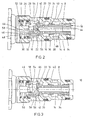
- Figure 1 shows a partial section of a continuously adjustable directional control valve 1 with an inlet port 2 and a drain port 4. It is assumed that the inlet port 2 is connected to a consumer and thus subjected to a load pressure, while the drain port 4 connected to a tank or the like is.
- the directional control valve 1 is designed in Cartridgebau way and has a valve sleeve 6 on which the two terminals 2, 4 are formed and in the bore 8, a seat slide 10 is guided axially displaceable.
- the actuation of the seat slide 10 by means of a proportional solenoid 12, which is designed in the illustrated embodiment as a pulling magnet.
- the proportional solenoid 12 is screwed to the valve sleeve 6. Further details of the directional control valve 1 will be explained with reference to the enlarged view in FIG.
- the bore 8 of the valve sleeve 6 is expanded in the radial direction to a drain chamber 14, an overflow 16 and an inlet chamber 18, wherein the drain chamber 14 opens in the running as a bore star radially opening drain port 4 and the inlet chamber 18 in the likewise designed as a bore star inlet port 2.
- a valve seat 22 is formed at a web 20 of the valve sleeve 6 between the overflow 16 and the inlet chamber 18.
- the overflow 16 is separated from the discharge chamber 14 by a control ridge 24 of the valve sleeve 6, which limits the flow cross section together with the seat slide 10 described in more detail below in the directional control valve function.
- a spring chamber 26 connects, which is extended over a radial shoulder 28 in the radial direction with respect to the inlet space 18.
- a control spring 30 is supported via a spring plate 32.
- the seat slide 10 has at its end remote from the valve seat 22 end portion a guide collar 34 which bears sealingly against the inner peripheral surface of the bore 8.
- control collar 36 which is formed in the illustrated basic position approximately in the region of the web 24.
- the control collar 36 is provided to the drain chamber 14 with control notches 38 through which a control edge 40 is formed.
- This control edge 40 is covered in the illustrated basic position of the peripheral surface of the control bar 24, so that the connection between the overflow 16 and the drain chamber 14 is shut off. This connection is opened only after passing through an initial stroke of the seat slide 10.
- a closing cone 42 is provided, which rests in the illustrated basic position with its conical surface on the valve seat 22, so that it is closed.
- a driving claw 46 On an end face 44 of the closing cone 42, a driving claw 46 is formed, which has a radially extending, unilaterally closed claw recess 48.
- This driving claw 46 is in engagement with a plunger 50, which has at its illustrated end portion an annular groove which is bounded by two annular shoulders 52 and 54.
- the right in Figure 2 annular shoulder 54 is formed by an annular ridge, to which a pilot valve cone 56 connects.
- the driving claw 46 has a driving shoulder 58, which in the illustrated basic position in Axial distance to the annular shoulder 54 of the plunger 50 is arranged.
- the plunger 50 is guided axially displaceably with an armature 60 in a pole tube 62 of the proportional magnet 12 and can be moved by energizing the coil (not shown) of the proportional magnet 12 in the illustration of Figure 1 from its basic position to the left.
- the plunger 50 with the pilot valve cone 56 and the armature 60 are biased by a Nachfuelfeder 64 in the illustrated basic position.
- the pilot valve cone 56 rests on a pilot valve seat 66 which opens into the end face 44 of the seat slide 10. This is extended in Figure 2 to the right towards an axial bore 68 of the seat slide 10.
- jacket holes 70 are provided, via which the axial bore 68 is connected to the overflow 16.
- the proportional solenoid 12 is de-energized in the basic position of the directional valve according to the invention, so that the pilot valve cone 56 is seated on the pilot valve seat 66.
- the closing cone 42 rests on the valve seat 22 and the control edge 40 has the connection between the discharge chamber 14 and the overflow 16 controlled.
- this load is shut off from the tank by the two valve seats (closing cone 42 / valve seat 22, pilot valve cone 56 / pilot valve seat 66) without leakage.
- the pilot valve cone 56 and the closing cone 42 are doing with a dependent of the load pressure Force and the force of Nach2001feder 64 pressed against the respectively zu simplifyen valve seat 66 and 22 respectively.
- the proportional solenoid is energized, the current is selected so that the plunger 50 can be lifted with the pilot valve cone 56 from its pilot valve seat 66 against the load pressure corresponding force.
- the magnetic force must be chosen so that the pilot poppet 56 can be reliably lifted even at the largest effective load pressure, for example, at the level of 450 bar.
- Figure 3 shows the directional control valve 1 with open pilot control.
- the pilot valve seat 66 When the pilot valve cone 56 is lifted, the pilot valve seat 66 is opened, so that pressure medium can enter the axial bore 68 from the inlet chamber 18, so that the right-hand end face of the seat slide 10 in FIG. 3 is subjected to the load pressure. This is above the casing bores 70 in the overflow 16, so that the back of the closing cone 42 is also acted upon by the load pressure.
- the diameter of the valve seat 22 is greater than the diameter of the guide collar 34, i. that part of the seat slide 10 which is guided in the bore 8. The seat slide 10 is thus pressure balanced, so that its axial displacement a comparatively small force is required, which can be applied by the proportional magnet.
- the load pressure introduction into the overflow chamber 16 has the advantage that even if over the life of the directional control valve 1 away from a change in the valve seat diameter results in a pressure relief of the seat slide 10 by the introduction of the load pressure in the overflow 16 is still guaranteed - There is thus a kind of automatic adaptation to such signs of wear.
- the driving claw 46 runs as shown in FIG. 4 with a shoulder 72 on the spring plate 32, so that the further axial displacement must take place against the force of the comparatively strong control spring 30.
- the closing cone 42 is then lifted off the valve seat 22, so that a connection from the inlet chamber 18 to the overflow chamber 16 via the valve seat 22 is opened.
- the connection from the overflow chamber 16 to the discharge chamber 14 is not opened by the control edge 40 or at least to a negligible extent.
- the force of the control spring 30 is designed so that the magnetic force, which was just enough to pull the plunger 50 in the manner described above with the seat slide 10 in the abutment position on the spring plate 32 is insufficient to further axial displacement of the seat slide 10th to enable in its way valve function.
- the directional control valve 1 has a flow behavior which is independent of load pressure to a certain extent.
- the seat slide 10 is acted upon in accordance with the applied load pressure by flow forces against the predetermined by the proportional solenoid 12 direction of movement in the closing direction, whereby the controlled by the control notches 38 flow cross-section is reduced, so that the discharge amount remains independent of load pressure approximately the same.
- this load pressure-independent constant flow does not work as well as with an individual pressure balance - in many applications, however, the achievable accuracy is sufficient.
- the driving claw 46 runs with the shoulder 72 on the spring plate 32, so that the further displacement of the plunger 50 and thus the axial displacement of the seat slide 10 is possible only by increasing the magnetic force. That After the stroke s1, the magnetic force is increased again, so that the seat slide 10 is moved against the force of the control spring 30.
- the stroke of the plunger 50 and thus the seat slide 10 is in this way valve function substantially proportional to the magnetic force F.
- the pilot control can be opened even at the maximum possible load pressure of, for example, 450 bar.
- a continuously adjustable directional control valve with a seat slide on which a valve cone is formed is, which is biased in the basic position of the directional control valve against a valve seat.
- the directional control valve is formed with a pilot control, for which purpose a pilot valve seat is provided in the closing cone, which cooperates with a pilot valve cone.
Landscapes
- Engineering & Computer Science (AREA)
- General Engineering & Computer Science (AREA)
- Mechanical Engineering (AREA)
- Physics & Mathematics (AREA)
- Fluid Mechanics (AREA)
- Magnetically Actuated Valves (AREA)
- Fluid-Driven Valves (AREA)
Applications Claiming Priority (3)
| Application Number | Priority Date | Filing Date | Title |
|---|---|---|---|
| DE10316770 | 2003-04-10 | ||
| DE10322970A DE10322970A1 (de) | 2003-04-10 | 2003-05-21 | Stetig verstellbares Wegeventil |
| PCT/DE2004/000708 WO2004092591A1 (de) | 2003-04-10 | 2004-04-05 | Stetig verstellbares wegeventil |
Publications (2)
| Publication Number | Publication Date |
|---|---|
| EP1611358A1 EP1611358A1 (de) | 2006-01-04 |
| EP1611358B1 true EP1611358B1 (de) | 2007-10-24 |
Family
ID=33300829
Family Applications (1)
| Application Number | Title | Priority Date | Filing Date |
|---|---|---|---|
| EP04725668A Expired - Lifetime EP1611358B1 (de) | 2003-04-10 | 2004-04-05 | Stetig verstellbares wegeventil |
Country Status (6)
| Country | Link |
|---|---|
| US (1) | US7392971B2 (ko) |
| EP (1) | EP1611358B1 (ko) |
| KR (1) | KR101105257B1 (ko) |
| AT (1) | ATE376624T1 (ko) |
| DE (1) | DE502004005325D1 (ko) |
| WO (1) | WO2004092591A1 (ko) |
Families Citing this family (6)
| Publication number | Priority date | Publication date | Assignee | Title |
|---|---|---|---|---|
| DE102004051575B4 (de) * | 2004-10-22 | 2015-12-17 | Bosch Rexroth Aktiengesellschaft | Wegesitzventil |
| CN103047426B (zh) * | 2013-01-11 | 2014-05-07 | 浙江大学台州研究院 | 气动比例压力阀 |
| WO2017050327A1 (de) * | 2015-09-21 | 2017-03-30 | Schaeffler Technologies AG & Co. KG | Steuerventil für einen nockenwellenversteller |
| US10458557B2 (en) * | 2016-04-20 | 2019-10-29 | Sikorsky Aircraft Corporation | Hydraulic actuator force fight mitigation mechanism |
| US11060626B2 (en) * | 2017-02-24 | 2021-07-13 | Merck Patent Gmbh | Fluid distributor valve and water purification and dispensing system using the same |
| KR102108437B1 (ko) * | 2018-05-17 | 2020-05-07 | 조도연 | 밸브 라이닝 장치 및 라이닝 밸브 |
Family Cites Families (10)
| Publication number | Priority date | Publication date | Assignee | Title |
|---|---|---|---|---|
| US2575272A (en) * | 1947-07-17 | 1951-11-13 | Skinner Chuck Company | Rapid closure valve for high-flow rates at low-pressure drop |
| US2968464A (en) * | 1955-12-20 | 1961-01-17 | Marotta Valve Corp | Pressure operated valve with magnetically actuated pilot |
| US4699351A (en) * | 1984-07-11 | 1987-10-13 | Target Rock Corporation | Pressure responsive, pilot actuated, modulating valve |
| CH671080A5 (ko) * | 1986-10-01 | 1989-07-31 | Sulzer Ag | |
| US5048790A (en) * | 1990-07-18 | 1991-09-17 | Target Rock Corporation | Self-modulating control valve for high-pressure fluid flow |
| JPH0652109A (ja) * | 1992-07-29 | 1994-02-25 | Toshiba Corp | メッセージ通信のセキュリティ方式 |
| DE19535223A1 (de) | 1995-09-22 | 1997-03-27 | Bosch Gmbh Robert | Längsschieberventil mit großflächigem Ventilsitz |
| DE19627306A1 (de) | 1996-07-06 | 1998-01-08 | Bosch Gmbh Robert | Sperrventil mit Druckbegrenzung |
| DE10030059B4 (de) | 2000-06-19 | 2006-01-05 | Buchholz Hydraulik Gmbh | Steuereinrichtung |
| DE10048600B4 (de) | 2000-09-30 | 2010-09-16 | Robert Bosch Gmbh | Steuerungsvorrichtung für einen hydraulischen Volumenstrom |
-
2004
- 2004-04-05 DE DE200450005325 patent/DE502004005325D1/de not_active Expired - Lifetime
- 2004-04-05 EP EP04725668A patent/EP1611358B1/de not_active Expired - Lifetime
- 2004-04-05 US US10/551,992 patent/US7392971B2/en not_active Expired - Fee Related
- 2004-04-05 AT AT04725668T patent/ATE376624T1/de not_active IP Right Cessation
- 2004-04-05 WO PCT/DE2004/000708 patent/WO2004092591A1/de active IP Right Grant
- 2004-04-05 KR KR1020057019243A patent/KR101105257B1/ko not_active IP Right Cessation
Also Published As
| Publication number | Publication date |
|---|---|
| US20060289073A1 (en) | 2006-12-28 |
| KR20050118728A (ko) | 2005-12-19 |
| US7392971B2 (en) | 2008-07-01 |
| ATE376624T1 (de) | 2007-11-15 |
| DE502004005325D1 (de) | 2007-12-06 |
| EP1611358A1 (de) | 2006-01-04 |
| WO2004092591A1 (de) | 2004-10-28 |
| KR101105257B1 (ko) | 2012-01-17 |
Similar Documents
| Publication | Publication Date | Title |
|---|---|---|
| DE102009055802A1 (de) | Sitzventil betätigt durch elektrohydraulisches Vorsteuersitzventil | |
| EP1781952B1 (de) | Hydraulische steueranordnung | |
| EP1625307B1 (de) | Ventil | |
| EP0279315B1 (de) | Hydraulische Steuervorrichtung | |
| DE102010063386A1 (de) | Verstellbare Dämpfventileinrichtung | |
| DE102011116393B3 (de) | Vorsteuerstufe eines proportional gesteuerten Hydraulikventils | |
| DE102007010213B3 (de) | Elektromagnetisches Regelventil und Verfahren zu dessen Steuerung | |
| EP1032375A1 (de) | Hydraulisches wegeventil | |
| EP1611358B1 (de) | Stetig verstellbares wegeventil | |
| WO2010072201A1 (de) | Vorgesteuertes ventil und ventilgesteuerte hydromaschine | |
| WO2006105765A1 (de) | Wegeventil und damit ausgeführte ls-steueranordnung | |
| EP2799722B1 (de) | Hydrauliksteuerung | |
| DE102015111222A1 (de) | Lastkompensiertes Proportional-Drosselventil | |
| EP1623123B1 (de) | Hydraulische steueranordnung | |
| DE19729387A1 (de) | Prioritätsvariable Vorrichtung für ein Hydrauliksystem von Baugerät | |
| DE102007033498A1 (de) | Sitzventilanordnung | |
| DE102005056029A1 (de) | Hydrauliksystem mit wenigstens einem Hydraulikventil zum Ansteuern einer Komponente | |
| DE10023583B4 (de) | Elektrohydraulischer Senken-Modul | |
| DE102008064409A1 (de) | Vorgesteuertes Ventil und ventilgesteuerte Hydromaschine | |
| DE19925204B4 (de) | Entsperrbares Lasthalteventil | |
| EP1369596B1 (de) | Hydraulische Ventilanordnung | |
| DE10322970A1 (de) | Stetig verstellbares Wegeventil | |
| DE19714505B4 (de) | Rückschlagventil | |
| DE10048600B4 (de) | Steuerungsvorrichtung für einen hydraulischen Volumenstrom | |
| WO2018001549A1 (de) | Einrichtung zur strömungskraft-kompensation |
Legal Events
| Date | Code | Title | Description |
|---|---|---|---|
| PUAI | Public reference made under article 153(3) epc to a published international application that has entered the european phase |
Free format text: ORIGINAL CODE: 0009012 |
|
| 17P | Request for examination filed |
Effective date: 20051025 |
|
| AK | Designated contracting states |
Kind code of ref document: A1 Designated state(s): AT BE BG CH CY CZ DE DK EE ES FI FR GB GR HU IE IT LI LU MC NL PL PT RO SE SI SK TR |
|
| AX | Request for extension of the european patent |
Extension state: AL HR LT LV MK |
|
| DAX | Request for extension of the european patent (deleted) | ||
| 17Q | First examination report despatched |
Effective date: 20060302 |
|
| GRAP | Despatch of communication of intention to grant a patent |
Free format text: ORIGINAL CODE: EPIDOSNIGR1 |
|
| GRAS | Grant fee paid |
Free format text: ORIGINAL CODE: EPIDOSNIGR3 |
|
| GRAA | (expected) grant |
Free format text: ORIGINAL CODE: 0009210 |
|
| AK | Designated contracting states |
Kind code of ref document: B1 Designated state(s): AT BE BG CH CY CZ DE DK EE ES FI FR GB GR HU IE IT LI LU MC NL PL PT RO SE SI SK TR |
|
| REG | Reference to a national code |
Ref country code: GB Ref legal event code: FG4D Free format text: NOT ENGLISH |
|
| REG | Reference to a national code |
Ref country code: CH Ref legal event code: EP |
|
| REG | Reference to a national code |
Ref country code: IE Ref legal event code: FG4D Free format text: LANGUAGE OF EP DOCUMENT: GERMAN |
|
| REF | Corresponds to: |
Ref document number: 502004005325 Country of ref document: DE Date of ref document: 20071206 Kind code of ref document: P |
|
| GBT | Gb: translation of ep patent filed (gb section 77(6)(a)/1977) |
Effective date: 20080206 |
|
| NLV1 | Nl: lapsed or annulled due to failure to fulfill the requirements of art. 29p and 29m of the patents act | ||
| PG25 | Lapsed in a contracting state [announced via postgrant information from national office to epo] |
Ref country code: ES Free format text: LAPSE BECAUSE OF FAILURE TO SUBMIT A TRANSLATION OF THE DESCRIPTION OR TO PAY THE FEE WITHIN THE PRESCRIBED TIME-LIMIT Effective date: 20080204 Ref country code: NL Free format text: LAPSE BECAUSE OF FAILURE TO SUBMIT A TRANSLATION OF THE DESCRIPTION OR TO PAY THE FEE WITHIN THE PRESCRIBED TIME-LIMIT Effective date: 20071024 Ref country code: SE Free format text: LAPSE BECAUSE OF FAILURE TO SUBMIT A TRANSLATION OF THE DESCRIPTION OR TO PAY THE FEE WITHIN THE PRESCRIBED TIME-LIMIT Effective date: 20080124 |
|
| PG25 | Lapsed in a contracting state [announced via postgrant information from national office to epo] |
Ref country code: PT Free format text: LAPSE BECAUSE OF FAILURE TO SUBMIT A TRANSLATION OF THE DESCRIPTION OR TO PAY THE FEE WITHIN THE PRESCRIBED TIME-LIMIT Effective date: 20080324 Ref country code: PL Free format text: LAPSE BECAUSE OF FAILURE TO SUBMIT A TRANSLATION OF THE DESCRIPTION OR TO PAY THE FEE WITHIN THE PRESCRIBED TIME-LIMIT Effective date: 20071024 Ref country code: SI Free format text: LAPSE BECAUSE OF FAILURE TO SUBMIT A TRANSLATION OF THE DESCRIPTION OR TO PAY THE FEE WITHIN THE PRESCRIBED TIME-LIMIT Effective date: 20071024 Ref country code: BG Free format text: LAPSE BECAUSE OF FAILURE TO SUBMIT A TRANSLATION OF THE DESCRIPTION OR TO PAY THE FEE WITHIN THE PRESCRIBED TIME-LIMIT Effective date: 20080124 |
|
| REG | Reference to a national code |
Ref country code: IE Ref legal event code: FD4D |
|
| PG25 | Lapsed in a contracting state [announced via postgrant information from national office to epo] |
Ref country code: CZ Free format text: LAPSE BECAUSE OF FAILURE TO SUBMIT A TRANSLATION OF THE DESCRIPTION OR TO PAY THE FEE WITHIN THE PRESCRIBED TIME-LIMIT Effective date: 20071024 Ref country code: DK Free format text: LAPSE BECAUSE OF FAILURE TO SUBMIT A TRANSLATION OF THE DESCRIPTION OR TO PAY THE FEE WITHIN THE PRESCRIBED TIME-LIMIT Effective date: 20071024 |
|
| EN | Fr: translation not filed | ||
| PG25 | Lapsed in a contracting state [announced via postgrant information from national office to epo] |
Ref country code: RO Free format text: LAPSE BECAUSE OF FAILURE TO SUBMIT A TRANSLATION OF THE DESCRIPTION OR TO PAY THE FEE WITHIN THE PRESCRIBED TIME-LIMIT Effective date: 20071024 Ref country code: SK Free format text: LAPSE BECAUSE OF FAILURE TO SUBMIT A TRANSLATION OF THE DESCRIPTION OR TO PAY THE FEE WITHIN THE PRESCRIBED TIME-LIMIT Effective date: 20071024 |
|
| PLBE | No opposition filed within time limit |
Free format text: ORIGINAL CODE: 0009261 |
|
| STAA | Information on the status of an ep patent application or granted ep patent |
Free format text: STATUS: NO OPPOSITION FILED WITHIN TIME LIMIT |
|
| 26N | No opposition filed |
Effective date: 20080725 |
|
| BERE | Be: lapsed |
Owner name: BOSCH REXROTH A.G. Effective date: 20080430 |
|
| PG25 | Lapsed in a contracting state [announced via postgrant information from national office to epo] |
Ref country code: IE Free format text: LAPSE BECAUSE OF FAILURE TO SUBMIT A TRANSLATION OF THE DESCRIPTION OR TO PAY THE FEE WITHIN THE PRESCRIBED TIME-LIMIT Effective date: 20071024 Ref country code: FR Free format text: LAPSE BECAUSE OF FAILURE TO SUBMIT A TRANSLATION OF THE DESCRIPTION OR TO PAY THE FEE WITHIN THE PRESCRIBED TIME-LIMIT Effective date: 20080808 |
|
| PG25 | Lapsed in a contracting state [announced via postgrant information from national office to epo] |
Ref country code: MC Free format text: LAPSE BECAUSE OF NON-PAYMENT OF DUE FEES Effective date: 20080430 |
|
| REG | Reference to a national code |
Ref country code: CH Ref legal event code: PL |
|
| PG25 | Lapsed in a contracting state [announced via postgrant information from national office to epo] |
Ref country code: CH Free format text: LAPSE BECAUSE OF NON-PAYMENT OF DUE FEES Effective date: 20080430 Ref country code: EE Free format text: LAPSE BECAUSE OF FAILURE TO SUBMIT A TRANSLATION OF THE DESCRIPTION OR TO PAY THE FEE WITHIN THE PRESCRIBED TIME-LIMIT Effective date: 20071024 Ref country code: GR Free format text: LAPSE BECAUSE OF FAILURE TO SUBMIT A TRANSLATION OF THE DESCRIPTION OR TO PAY THE FEE WITHIN THE PRESCRIBED TIME-LIMIT Effective date: 20080125 Ref country code: LI Free format text: LAPSE BECAUSE OF NON-PAYMENT OF DUE FEES Effective date: 20080430 |
|
| PG25 | Lapsed in a contracting state [announced via postgrant information from national office to epo] |
Ref country code: FI Free format text: LAPSE BECAUSE OF FAILURE TO SUBMIT A TRANSLATION OF THE DESCRIPTION OR TO PAY THE FEE WITHIN THE PRESCRIBED TIME-LIMIT Effective date: 20071024 |
|
| PG25 | Lapsed in a contracting state [announced via postgrant information from national office to epo] |
Ref country code: BE Free format text: LAPSE BECAUSE OF NON-PAYMENT OF DUE FEES Effective date: 20080430 |
|
| PG25 | Lapsed in a contracting state [announced via postgrant information from national office to epo] |
Ref country code: CY Free format text: LAPSE BECAUSE OF FAILURE TO SUBMIT A TRANSLATION OF THE DESCRIPTION OR TO PAY THE FEE WITHIN THE PRESCRIBED TIME-LIMIT Effective date: 20071024 |
|
| PG25 | Lapsed in a contracting state [announced via postgrant information from national office to epo] |
Ref country code: AT Free format text: LAPSE BECAUSE OF NON-PAYMENT OF DUE FEES Effective date: 20080405 |
|
| PG25 | Lapsed in a contracting state [announced via postgrant information from national office to epo] |
Ref country code: LU Free format text: LAPSE BECAUSE OF NON-PAYMENT OF DUE FEES Effective date: 20080405 Ref country code: HU Free format text: LAPSE BECAUSE OF FAILURE TO SUBMIT A TRANSLATION OF THE DESCRIPTION OR TO PAY THE FEE WITHIN THE PRESCRIBED TIME-LIMIT Effective date: 20080425 |
|
| PG25 | Lapsed in a contracting state [announced via postgrant information from national office to epo] |
Ref country code: TR Free format text: LAPSE BECAUSE OF FAILURE TO SUBMIT A TRANSLATION OF THE DESCRIPTION OR TO PAY THE FEE WITHIN THE PRESCRIBED TIME-LIMIT Effective date: 20071024 |
|
| PGFP | Annual fee paid to national office [announced via postgrant information from national office to epo] |
Ref country code: GB Payment date: 20130422 Year of fee payment: 10 Ref country code: DE Payment date: 20130627 Year of fee payment: 10 |
|
| PGFP | Annual fee paid to national office [announced via postgrant information from national office to epo] |
Ref country code: IT Payment date: 20130424 Year of fee payment: 10 |
|
| REG | Reference to a national code |
Ref country code: DE Ref legal event code: R119 Ref document number: 502004005325 Country of ref document: DE |
|
| GBPC | Gb: european patent ceased through non-payment of renewal fee |
Effective date: 20140405 |
|
| REG | Reference to a national code |
Ref country code: DE Ref legal event code: R119 Ref document number: 502004005325 Country of ref document: DE Effective date: 20141101 |
|
| PG25 | Lapsed in a contracting state [announced via postgrant information from national office to epo] |
Ref country code: GB Free format text: LAPSE BECAUSE OF NON-PAYMENT OF DUE FEES Effective date: 20140405 Ref country code: DE Free format text: LAPSE BECAUSE OF NON-PAYMENT OF DUE FEES Effective date: 20141101 |
|
| PG25 | Lapsed in a contracting state [announced via postgrant information from national office to epo] |
Ref country code: IT Free format text: LAPSE BECAUSE OF NON-PAYMENT OF DUE FEES Effective date: 20140405 |