EP1611045B1 - Procede de commande de palonnier de grue - Google Patents
Procede de commande de palonnier de grue Download PDFInfo
- Publication number
- EP1611045B1 EP1611045B1 EP04724302A EP04724302A EP1611045B1 EP 1611045 B1 EP1611045 B1 EP 1611045B1 EP 04724302 A EP04724302 A EP 04724302A EP 04724302 A EP04724302 A EP 04724302A EP 1611045 B1 EP1611045 B1 EP 1611045B1
- Authority
- EP
- European Patent Office
- Prior art keywords
- auxiliary
- rope
- ropes
- gear
- spreader
- Prior art date
- Legal status (The legal status is an assumption and is not a legal conclusion. Google has not performed a legal analysis and makes no representation as to the accuracy of the status listed.)
- Expired - Lifetime
Links
- 238000000034 method Methods 0.000 title claims abstract description 24
- 230000003068 static effect Effects 0.000 claims abstract description 12
- 230000001133 acceleration Effects 0.000 claims description 2
- 238000010586 diagram Methods 0.000 description 2
- 238000005303 weighing Methods 0.000 description 2
- 238000006243 chemical reaction Methods 0.000 description 1
- 230000008092 positive effect Effects 0.000 description 1
- 230000004224 protection Effects 0.000 description 1
Images

Classifications
-
- B—PERFORMING OPERATIONS; TRANSPORTING
- B66—HOISTING; LIFTING; HAULING
- B66C—CRANES; LOAD-ENGAGING ELEMENTS OR DEVICES FOR CRANES, CAPSTANS, WINCHES, OR TACKLES
- B66C13/00—Other constructional features or details
- B66C13/04—Auxiliary devices for controlling movements of suspended loads, or preventing cable slack
- B66C13/06—Auxiliary devices for controlling movements of suspended loads, or preventing cable slack for minimising or preventing longitudinal or transverse swinging of loads
- B66C13/063—Auxiliary devices for controlling movements of suspended loads, or preventing cable slack for minimising or preventing longitudinal or transverse swinging of loads electrical
Definitions
- the invention relates to a method for controlling swaying and swinging of a spreader in a crane and the load attached thereto, the crane comprising: a trolley, hoist gears provided with hoist drums placed in the trolley, hoisting ropes arranged on the hoist drums, on which the spreader is suspended from the trolley and which are directed back to the trolley through sheaves arranged on the spreader, whereby the swaying and swinging is controlled by control equipment comprising: four auxiliary gears provided with rope drums including motors and motor control equipment placed in the trolley, auxiliary ropes arranged on the rope drums of the auxiliary gears, sheaves for the auxiliary ropes placed in the spreader, through which sheaves the auxiliary ropes passing obliquely from the rope drums of the auxiliary gears are directed to spaces arranged in the hoist drums for the auxiliary ropes, and in which method the forces of the auxiliary ropes exerted on the spreader are controlled by moving the auxiliary napes using the auxiliary gears by means of
- the method of the invention is known from FI patent 101466, in which the method is presented in connection with a crane moving by means of rubber tyres and whose hoisting heights and hoisting speeds are moderate.
- the static torque instruction is calculated on the basis of the reference value of the rope force in the auxiliary gear, the measuring data of the rope force and the rotating speed of the auxiliary gear, and the dynamic torque instruction, i.e. the dynamic feedforward term, is calculated from the change occurring in the calculated rotating speed of the auxiliary gear.
- the method according to the invention allows removing the rough and jerky correcting movements of the spreader and the load from the cranes built for high speeds and hoisting heights, which have made the use of the method known from FI patent 101466 impossible as such.
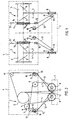
- the crane arrangement shown in the drawings known for instance from FI patent 108788, comprises two hoist gears 2 with hoist drums 3 placed in a crane trolley 1. These elements are arranged in the trolley 1 such that the longitudinal axes thereof are in the same line A.
- Two hoisting ropes 4 are arranged in parallel on the hoist drum 3 of both hoist gears 2 so that grooves 5 and 6 reserved for the ropes on the surface of the hoist drum 3 are opposite in direction.
- a spreader 7 for fastening a load to be hoisted (not shown) is suspended on the hoisting ropes 4.
- the spreader is provided with sheaves 8 for the hoisting ropes 4, through which the hoisting ropes 4 are directed back to the trolley 1.
- the sheaves 8 are placed in the spreader 7 substantially directly below the longitudinal middle points of the hoist drums 3, whereby the position of the hoisting ropes remains substantially symmetrical in the vertical direction despite the different hoisting heights.
- the hoisting ropes 4 are directed to the trolley 1 through additional sheaves 9 and secured to the crane through possible overload protections (not shown).
- the arrangement also comprises four auxiliary gears 10 placed in the trolley 1 for controlling swaying and swinging of the spreader 7 and the load attached thereto.
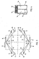
- the auxiliary gears 10 are arranged in a rectangle (although an asymmetrical arrangement is also possible) so that one auxiliary gear 10 is located in each corner of the rectangle.
- a rope drum 11 of each auxiliary gear 10 is provided with an auxiliary rope 12 that passes obliquely into sheaves 13 located in the spreader 7 and through them back towards the hoist drums 3 and into spaces 14, which are preferably designed and reserved for them in the hoist drums 3.
- the sheaves 13 are also preferably arranged in a rectangle so that one sheave 13 is located in each corner of the rectangle.
- auxiliary ropes 12 It is necessary to arrange the auxiliary ropes 12 obliquely in order that the vertical forces required to prevent or reduce swaying or swinging could be exerted on the spreader 7 and the load by means of the auxiliary gears 12 and the auxiliary ropes. Consequently, the hoisting ropes 4 can also be positioned completely vertically. The control of such swaying and swinging will be described below.
- the auxiliary ropes 12 are preferably provided with at least one set of additional sheaves 15 arranged in the trolley 1, through which sheaves the auxiliary ropes 12 arriving from the spreader 7 and the first set of sheaves 13 therein are directed to auxiliary rope spaces 14 of the hoist drums 3.
- each auxiliary rope 12 is provided with a stationary point in the trolley 1 relative thereto and independent of the hoisting height, whereby the movement of the auxiliary ropes 12 in relation to the drum on the side of the trolley 1 is avoided.
- the spaces 14 for the auxiliary ropes are formed at the ends of the hoist drums 3 within a considerably narrow area, for instance by means of flanges 16, so that the auxiliary ropes 12 can be wound onto a plurality of layers, in which case the angle of the auxiliary ropes 12 in relation to the hoist drum 3 remains almost constant at any hoisting height, and the hoist drum 3 is made considerably shorter than previously.
- sheaves 17, through which the auxiliary ropes 12 pass are sheaves 17, through which the auxiliary ropes 12 pass, but these are mainly arranged to ensure an unobstructed passage for the auxiliary ropes 12.
- the auxiliary gears 10 can be, for instance, identical, mechanically independent systems, the control of which is implemented totally electrically and determined on the basis of the weighting data of the auxiliary rope 12, the rotating speed of the rope drum 11 i.e. the auxiliary gear 10, and similar variables.
- a sufficient amount of auxiliary rope 12 is always stored on the rope drum 11, and thereby the compensation created by different geometries of the auxiliary ropes 12 and the hoist ropes 4 will be automatically solved.
- the forces exerted on each auxiliary rope 12 are controlled on the basis of the above-mentioned variables in such a manner that the spreader 7 and the load suspended thereto are not allowed to sway or swing. It is not necessary to place the auxiliary gears 10 totally symmetrically, since the above-mentioned control logic is able to take into account the asymmetry, if it is known in advance.
- a static torque instruction T stat is gear-specifically calculated for each auxiliary gear 10 by means of a separately arranged feedback control logic circuit C, which may, for instance, refer to a circuit known from FI patent 101466 comprising a force controller and a speed controller, in which the static torque instruction T stat is calculated on the basis of the reference value F ref of the rope force in each auxiliary gear 10, the measuring data of the rope force F rope and the rotating speed n of the auxiliary gear 10.
- the rope force F rope may represent a piece of information measured by means of an appropriate weighing sensor or the rope force can be calculated from the actual value of the torque determined by the motor control equipment (for example a frequency converter) in the auxiliary gear 10 as will be shown below.
- the rotating speed n shows, in turn, how the load sways from the position of equilibrium thereof. Setting the reference value F ref of the rope force is described in detail in the above-mentioned patent and will therefore not be described in more detail in this context.
- this static torque instruction T stat obtained in a previously known manner the gear-specific dynamic torque instruction T dyn, calc according to the invention, i.e. a dynamic feedforward term, which is calculated using a dynamic feedforward circuit D from the change in the calculated rotating speed n calc of each auxiliary gear 10.
- the gear-specific torque instruction T control by which the control of the spreader 7 and the load attached thereto can be implemented, provided for the motor control equipment in each auxiliary gear 10 is the sum of the static torque instruction T stat and the dynamic torque instruction T dyn, calc .
- T dyn, calc b ⁇ J ⁇ d / dt n calc , where
- each auxiliary rope 10 The force lifting the load of each auxiliary rope 10 is required for weighing the load. Since the dynamic additional torque T dyn, calc provided by the dynamic feedforward is at times high in order to accelerate the inertia masses of the auxiliary gear 10, the static conversion from the torque data T act provided by the motor control equipment to rope force F rope provides incorrect information about the rope force.
- the rope force F rope obtained must also be divided into a vertical and horizontal force component, so as to take the vertical component affecting the determination of the load into account.
Landscapes
- Engineering & Computer Science (AREA)
- Mechanical Engineering (AREA)
- Control And Safety Of Cranes (AREA)
- Jib Cranes (AREA)
- Load-Engaging Elements For Cranes (AREA)
Claims (5)
- Procédé de contrôle de l'oscillation et du balancement d'un palonnier de grue et de la charge fixée à ce dernier, la grue comprenant :un chariot (1),des treuils de levage (2) équipés de tambours de levage (3) placés dans le chariot (1),des câbles de levage (4) disposés sur les tambours de levage (3), au moyen desquels le palonnier (7) est suspendu au chariot (1) et qui sont renvoyés au chariot par le biais de poulies (8) disposées sur le palonnier,procédé dans lequel l'oscillation et le balancement sont contrôlés par un équipement de contrôle comprenant :caractérisé en ce que l'instruction de couple (Tcontrôle) des équipements de commande de moteurs dans chaque renvoi auxiliaire (10) est formée de manière spécifique au renvoi sous la forme d'une somme d'un terme statique (Tstat) et d'un terme dynamique (Tdyn, calc) de la force de câble.quatre renvois auxiliaires (10) équipés de tambours à câble (11) et comprenant des moteurs et des équipements de commande de moteurs placés dans le chariot (1),des câbles auxiliaires (12) disposés sur les tambours à câble (11) des renvois auxiliaires (10),des poulies (13) pour les câbles auxiliaires, placées dans le palonnier (7), les câbles auxiliaires (12) qui viennent obliquement des tambours à câble (11) des renvois auxiliaires (10) étant dirigés par lesdites poulies vers des espaces (14) ménagés dans les tambours de levage (2) pour les câbles auxiliaires,et procédé dans lequel les forces que les câbles auxiliaires (12) exercent sur le palonnier (7) sont contrôlées en déplaçant les câbles auxiliaires au moyen des renvois auxiliaires (10) en utilisant des instructions de couple (Tcontrôle) obtenues sur la base des forces de câble (Fcâble) exercées par les câbles auxiliaires et des données de vitesse de rotation (n) des renvois auxiliaires en utilisant une logique de commande (C) qui permet de fixer et de maintenir les forces de câbles voulues et qui commande la, rotation et la résistance au balancement des moteurs dans les renvois auxiliaires,
- Procédé selon la revendication 1, caractérisé en ce que l'instruction de couple statique (Tstat) est calculée sur la base d'une valeur de référence (Fréf) de la force de câble dans le renvoi auxiliaire (10), des données de mesure de la force de câble (Fcâble) et de la vitesse de rotation (n) du renvoi auxiliaire (10), et l'instruction de couple dynamique (Tdyn, calc) représentant le terme direct dynamique est calculée à partir de la variation de la vitesse de rotation calculée (ncalc) de chaque renvoi auxiliaire.
- Procédé selon la revendication 2, caractérisé en ce que le terme direct dynamique (Tdyn, calc) est calculé conformément à la formule suivante :
 b est un facteur d'échelle des unités,J est un paramètre de masse inertielle du renvoi auxiliaire (10), etd/dt(ncalc) est la variation de la vitesse calculée du renvoi auxiliaire (10) représentant la variation de vitesse voulue.
 - Procédé selon l'une quelconque des revendications précédentes, caractérisé en ce que, lors du calcul de la force de câble de chaque câble auxiliaire (12), le couple dynamique (Tdyn, act) nécessaire pour accélérer la masse du volant est réduit par rapport au couple moteur (Tcontrôle) calculé par les équipements de commande de moteurs, auquel cas le couple statique (Tstat, act) représentant la force de câble (Fcâble) est conservé.
- Procédé selon la revendication 4, caractérisé en ce que la force de câble (Fcâble) est calculée conformément à la formule suivante :
 b est un facteur d'échelle des unités,nact est la vitesse de rotation mesurée du renvoi auxiliaire (10) et d/dt(nact) est l'accélération mesurée du renvoi auxiliaire,J est un paramètre de masse inertielle du renvoi auxiliaire (10),k est un coefficient de conversion constant, etTact est la donnée de couple mise en oeuvre pour le renvoi auxiliaire (10).
Priority Applications (1)
| Application Number | Priority Date | Filing Date | Title |
|---|---|---|---|
| PL04724302T PL1611045T3 (pl) | 2003-04-01 | 2004-03-30 | Sposób sterowania trawersą dźwigu |
Applications Claiming Priority (2)
| Application Number | Priority Date | Filing Date | Title |
|---|---|---|---|
| FI20030485A FI115133B (fi) | 2003-04-01 | 2003-04-01 | Menetelmä nosturin kuormauselimen hallitsemiseksi |
| PCT/FI2004/000188 WO2004087555A1 (fr) | 2003-04-01 | 2004-03-30 | Procede de commande de palonnier de grue |
Publications (2)
| Publication Number | Publication Date |
|---|---|
| EP1611045A1 EP1611045A1 (fr) | 2006-01-04 |
| EP1611045B1 true EP1611045B1 (fr) | 2006-12-27 |
Family
ID=8565902
Family Applications (1)
| Application Number | Title | Priority Date | Filing Date |
|---|---|---|---|
| EP04724302A Expired - Lifetime EP1611045B1 (fr) | 2003-04-01 | 2004-03-30 | Procede de commande de palonnier de grue |
Country Status (13)
| Country | Link |
|---|---|
| US (1) | US7392915B2 (fr) |
| EP (1) | EP1611045B1 (fr) |
| JP (1) | JP4277023B2 (fr) |
| KR (1) | KR100627130B1 (fr) |
| CN (1) | CN100337901C (fr) |
| AT (1) | ATE349397T1 (fr) |
| DE (1) | DE602004003926T2 (fr) |
| DK (1) | DK1611045T3 (fr) |
| ES (1) | ES2277248T3 (fr) |
| FI (1) | FI115133B (fr) |
| PL (1) | PL1611045T3 (fr) |
| PT (1) | PT1611045E (fr) |
| WO (1) | WO2004087555A1 (fr) |
Families Citing this family (6)
| Publication number | Priority date | Publication date | Assignee | Title |
|---|---|---|---|---|
| EP1989129A2 (fr) * | 2006-03-02 | 2008-11-12 | Maff-Stack, LLC | Systeme d'entreposage pour embarcation de grande taille |
| FI119596B (fi) | 2007-08-24 | 2009-01-15 | Konecranes Oyj | Menetelmä nosturin ohjaamiseksi |
| NO337712B1 (no) * | 2010-03-24 | 2016-06-06 | Nat Oilwell Varco Norway As | Anordning og fremgangsmåte for å redusere dynamiske laster i kraner |
| DE102011001112A1 (de) * | 2011-03-04 | 2012-09-06 | Schneider Electric Automation Gmbh | Verfahren und Steuerungseinrichtung zur schwingungsarmen Bewegung eines bewegbaren Kranelementes eines Kransystems |
| CN106185624B (zh) * | 2016-08-31 | 2019-01-11 | 河南卫华机械工程研究院有限公司 | 起重机吊具防摇机构及防摇拉绳张力控制系统 |
| CN108639960B (zh) * | 2018-08-01 | 2024-02-06 | 上海振华重工电气有限公司 | 基于起重小车的全功能小车电气控制系统及其控制方法 |
Family Cites Families (7)
| Publication number | Priority date | Publication date | Assignee | Title |
|---|---|---|---|---|
| CN1019379B (zh) * | 1990-03-02 | 1992-12-09 | 章大章 | 集装箱起重机电气防摇装置 |
| JPH04303390A (ja) | 1991-04-01 | 1992-10-27 | Kobe Steel Ltd | 伸縮ブーム付クレーンの吊荷ワイヤ駆動制御装置 |
| JP3358768B2 (ja) * | 1995-04-26 | 2002-12-24 | 株式会社安川電機 | クレーン等のロープ振れ止め制御方法及び装置 |
| KR100314143B1 (ko) * | 1995-08-30 | 2001-12-28 | 튜보 린타마키, 타피오 하카카리 | 크레인의 로드와 로딩부 제어 장치 및 제어 방법 |
| JPH09158254A (ja) | 1995-12-05 | 1997-06-17 | Sumitomo Constr Mach Co Ltd | 掘削機の掘削制御装置 |
| FI20002030A0 (fi) * | 2000-09-14 | 2000-09-14 | Kci Kone Cranes Int Oy | Järjestely nosturin nostokoneiston apuköysien sijoittamiseksi |
| FI109990B (fi) * | 2001-03-23 | 2002-11-15 | Kci Kone Cranes Int Oy | Järjestely nosturin koneistojen sijoittamiseksi |
-
2003
- 2003-04-01 FI FI20030485A patent/FI115133B/fi not_active IP Right Cessation
-
2004
- 2004-03-30 AT AT04724302T patent/ATE349397T1/de not_active IP Right Cessation
- 2004-03-30 CN CNB2004800003023A patent/CN100337901C/zh not_active Expired - Lifetime
- 2004-03-30 DE DE602004003926T patent/DE602004003926T2/de not_active Expired - Lifetime
- 2004-03-30 DK DK04724302T patent/DK1611045T3/da active
- 2004-03-30 PT PT04724302T patent/PT1611045E/pt unknown
- 2004-03-30 KR KR1020047019447A patent/KR100627130B1/ko active IP Right Grant
- 2004-03-30 PL PL04724302T patent/PL1611045T3/pl unknown
- 2004-03-30 WO PCT/FI2004/000188 patent/WO2004087555A1/fr active IP Right Grant
- 2004-03-30 ES ES04724302T patent/ES2277248T3/es not_active Expired - Lifetime
- 2004-03-30 JP JP2005518191A patent/JP4277023B2/ja not_active Expired - Fee Related
- 2004-03-30 EP EP04724302A patent/EP1611045B1/fr not_active Expired - Lifetime
- 2004-03-30 US US10/515,252 patent/US7392915B2/en not_active Expired - Lifetime
Also Published As
| Publication number | Publication date |
|---|---|
| KR20050033049A (ko) | 2005-04-08 |
| US20050218099A1 (en) | 2005-10-06 |
| JP2006509700A (ja) | 2006-03-23 |
| US7392915B2 (en) | 2008-07-01 |
| JP4277023B2 (ja) | 2009-06-10 |
| DE602004003926D1 (de) | 2007-02-08 |
| PL1611045T3 (pl) | 2007-04-30 |
| ATE349397T1 (de) | 2007-01-15 |
| DE602004003926T2 (de) | 2007-05-03 |
| KR100627130B1 (ko) | 2006-09-25 |
| CN1697776A (zh) | 2005-11-16 |
| WO2004087555A1 (fr) | 2004-10-14 |
| EP1611045A1 (fr) | 2006-01-04 |
| FI20030485A (fi) | 2004-10-02 |
| DK1611045T3 (da) | 2007-04-30 |
| PT1611045E (pt) | 2007-02-28 |
| CN100337901C (zh) | 2007-09-19 |
| ES2277248T3 (es) | 2007-07-01 |
| FI20030485A0 (fi) | 2003-04-01 |
| FI115133B (fi) | 2005-03-15 |
Similar Documents
| Publication | Publication Date | Title |
|---|---|---|
| CA3017333C (fr) | Systeme et procede pour determiner une charge dans un systeme de manutention de materiau | |
| US7831333B2 (en) | Method for the automatic transfer of a load hanging at a load rope of a crane or excavator with a load oscillation damping and a trajectory planner | |
| US5961563A (en) | Anti-sway control for rotating boom cranes | |
| SA96170290B1 (ar) | طريقة وجهاز للتحكم في عنصر التحميل وحمولة رافعة | |
| US20180029849A1 (en) | Transport unit | |
| US6488128B1 (en) | Integrated shaft sensor for load measurement and torque control in elevators and escalators | |
| US9182270B2 (en) | Method and apparatus for measuring a load in a material handling system | |
| EP1611046B1 (fr) | Procede de controle de cadre de prehension de grue | |
| EP1611045B1 (fr) | Procede de commande de palonnier de grue | |
| US5806696A (en) | Method and equipment for controlling the operations of a crane | |
| CN115744634B (zh) | 塔式起重机及其控制方法、装置、处理器及云管理平台 | |
| CN115385247A (zh) | 用于塔式起重机的控制方法、处理器、装置及塔式起重机 | |
| JP4689374B2 (ja) | エレベータの制御装置及びエレベータの改修方法 | |
| Tomczyk et al. | The optimization of the flexibly suspended loads transport by microprocessor controlled overhead cranes | |
| JPS62121191A (ja) | 自動荷役装置 | |
| JP2022102576A (ja) | 循環式マルチカーエレベーター及び循環式マルチカーエレベーター制御方法 | |
| JPH10297871A (ja) | クレーンにおける回転振れ止め制御方法 | |
| KR20070095663A (ko) | 화물진동댐퍼 및 경로 제어기를 포함하는 크레인 또는굴착기의 케이블에 걸려 있는 화물의 자동이송방법 |
Legal Events
| Date | Code | Title | Description |
|---|---|---|---|
| PUAI | Public reference made under article 153(3) epc to a published international application that has entered the european phase |
Free format text: ORIGINAL CODE: 0009012 |
|
| 17P | Request for examination filed |
Effective date: 20050606 |
|
| AK | Designated contracting states |
Kind code of ref document: A1 Designated state(s): AT BE BG CH CY CZ DE DK EE ES FI FR GB GR HU IE IT LI LU MC NL PL PT RO SE SI SK TR |
|
| AX | Request for extension of the european patent |
Extension state: AL LT LV MK |
|
| DAX | Request for extension of the european patent (deleted) | ||
| GRAP | Despatch of communication of intention to grant a patent |
Free format text: ORIGINAL CODE: EPIDOSNIGR1 |
|
| GRAS | Grant fee paid |
Free format text: ORIGINAL CODE: EPIDOSNIGR3 |
|
| GRAA | (expected) grant |
Free format text: ORIGINAL CODE: 0009210 |
|
| AK | Designated contracting states |
Kind code of ref document: B1 Designated state(s): AT BE BG CH CY CZ DE DK EE ES FI FR GB GR HU IE IT LI LU MC NL PL PT RO SE SI SK TR |
|
| PG25 | Lapsed in a contracting state [announced via postgrant information from national office to epo] |
Ref country code: RO Free format text: LAPSE BECAUSE OF FAILURE TO SUBMIT A TRANSLATION OF THE DESCRIPTION OR TO PAY THE FEE WITHIN THE PRESCRIBED TIME-LIMIT Effective date: 20061227 Ref country code: CH Free format text: LAPSE BECAUSE OF FAILURE TO SUBMIT A TRANSLATION OF THE DESCRIPTION OR TO PAY THE FEE WITHIN THE PRESCRIBED TIME-LIMIT Effective date: 20061227 Ref country code: SK Free format text: LAPSE BECAUSE OF FAILURE TO SUBMIT A TRANSLATION OF THE DESCRIPTION OR TO PAY THE FEE WITHIN THE PRESCRIBED TIME-LIMIT Effective date: 20061227 Ref country code: SI Free format text: LAPSE BECAUSE OF FAILURE TO SUBMIT A TRANSLATION OF THE DESCRIPTION OR TO PAY THE FEE WITHIN THE PRESCRIBED TIME-LIMIT Effective date: 20061227 Ref country code: LI Free format text: LAPSE BECAUSE OF FAILURE TO SUBMIT A TRANSLATION OF THE DESCRIPTION OR TO PAY THE FEE WITHIN THE PRESCRIBED TIME-LIMIT Effective date: 20061227 Ref country code: AT Free format text: LAPSE BECAUSE OF FAILURE TO SUBMIT A TRANSLATION OF THE DESCRIPTION OR TO PAY THE FEE WITHIN THE PRESCRIBED TIME-LIMIT Effective date: 20061227 Ref country code: CZ Free format text: LAPSE BECAUSE OF FAILURE TO SUBMIT A TRANSLATION OF THE DESCRIPTION OR TO PAY THE FEE WITHIN THE PRESCRIBED TIME-LIMIT Effective date: 20061227 Ref country code: FI Free format text: LAPSE BECAUSE OF FAILURE TO SUBMIT A TRANSLATION OF THE DESCRIPTION OR TO PAY THE FEE WITHIN THE PRESCRIBED TIME-LIMIT Effective date: 20061227 |
|
| REG | Reference to a national code |
Ref country code: GB Ref legal event code: FG4D |
|
| REG | Reference to a national code |
Ref country code: IE Ref legal event code: FG4D |
|
| REF | Corresponds to: |
Ref document number: 602004003926 Country of ref document: DE Date of ref document: 20070208 Kind code of ref document: P |
|
| REG | Reference to a national code |
Ref country code: PT Ref legal event code: SC4A Free format text: AVAILABILITY OF NATIONAL TRANSLATION Effective date: 20070130 |
|
| REG | Reference to a national code |
Ref country code: GR Ref legal event code: EP Ref document number: 20070400606 Country of ref document: GR |
|
| PG25 | Lapsed in a contracting state [announced via postgrant information from national office to epo] |
Ref country code: BG Free format text: LAPSE BECAUSE OF FAILURE TO SUBMIT A TRANSLATION OF THE DESCRIPTION OR TO PAY THE FEE WITHIN THE PRESCRIBED TIME-LIMIT Effective date: 20070327 |
|
| REG | Reference to a national code |
Ref country code: SE Ref legal event code: TRGR |
|
| REG | Reference to a national code |
Ref country code: PL Ref legal event code: T3 Ref country code: DK Ref legal event code: T3 |
|
| REG | Reference to a national code |
Ref country code: CH Ref legal event code: PL |
|
| REG | Reference to a national code |
Ref country code: ES Ref legal event code: FG2A Ref document number: 2277248 Country of ref document: ES Kind code of ref document: T3 |
|
| ET | Fr: translation filed | ||
| PLBE | No opposition filed within time limit |
Free format text: ORIGINAL CODE: 0009261 |
|
| STAA | Information on the status of an ep patent application or granted ep patent |
Free format text: STATUS: NO OPPOSITION FILED WITHIN TIME LIMIT |
|
| 26N | No opposition filed |
Effective date: 20070928 |
|
| PG25 | Lapsed in a contracting state [announced via postgrant information from national office to epo] |
Ref country code: MC Free format text: LAPSE BECAUSE OF NON-PAYMENT OF DUE FEES Effective date: 20070331 |
|
| PG25 | Lapsed in a contracting state [announced via postgrant information from national office to epo] |
Ref country code: EE Free format text: LAPSE BECAUSE OF FAILURE TO SUBMIT A TRANSLATION OF THE DESCRIPTION OR TO PAY THE FEE WITHIN THE PRESCRIBED TIME-LIMIT Effective date: 20061227 |
|
| PG25 | Lapsed in a contracting state [announced via postgrant information from national office to epo] |
Ref country code: CY Free format text: LAPSE BECAUSE OF FAILURE TO SUBMIT A TRANSLATION OF THE DESCRIPTION OR TO PAY THE FEE WITHIN THE PRESCRIBED TIME-LIMIT Effective date: 20061227 Ref country code: LU Free format text: LAPSE BECAUSE OF NON-PAYMENT OF DUE FEES Effective date: 20070330 |
|
| PG25 | Lapsed in a contracting state [announced via postgrant information from national office to epo] |
Ref country code: TR Free format text: LAPSE BECAUSE OF FAILURE TO SUBMIT A TRANSLATION OF THE DESCRIPTION OR TO PAY THE FEE WITHIN THE PRESCRIBED TIME-LIMIT Effective date: 20061227 Ref country code: HU Free format text: LAPSE BECAUSE OF FAILURE TO SUBMIT A TRANSLATION OF THE DESCRIPTION OR TO PAY THE FEE WITHIN THE PRESCRIBED TIME-LIMIT Effective date: 20070628 |
|
| REG | Reference to a national code |
Ref country code: FR Ref legal event code: PLFP Year of fee payment: 12 |
|
| REG | Reference to a national code |
Ref country code: PT Ref legal event code: PC4A Owner name: KONECRANES GLOBAL CORPORATION, FI Effective date: 20151229 |
|
| REG | Reference to a national code |
Ref country code: DE Ref legal event code: R082 Ref document number: 602004003926 Country of ref document: DE Representative=s name: K & H BONAPAT PATENTANWAELTE KOCH VON BEHREN &, DE Ref country code: DE Ref legal event code: R081 Ref document number: 602004003926 Country of ref document: DE Owner name: KONECRANES GLOBAL CORP., FI Free format text: FORMER OWNER: KCI KONECRANES PLC, HYVINKAEAE, FI Ref country code: DE Ref legal event code: R082 Ref document number: 602004003926 Country of ref document: DE Representative=s name: K & H BONAPAT, DE Ref country code: DE Ref legal event code: R081 Ref document number: 602004003926 Country of ref document: DE Owner name: KONECRANES GLOBAL CORPORATION, FI Free format text: FORMER OWNER: KCI KONECRANES PLC, HYVINKAEAE, FI Ref country code: DE Ref legal event code: R082 Ref document number: 602004003926 Country of ref document: DE Representative=s name: K & H BONAPAT PATENTANWAELTE KOCH - VON BEHREN, DE |
|
| REG | Reference to a national code |
Ref country code: GB Ref legal event code: 732E Free format text: REGISTERED BETWEEN 20160204 AND 20160210 |
|
| REG | Reference to a national code |
Ref country code: ES Ref legal event code: PC2A Owner name: KONECRANES GLOBAL CORPORATION Effective date: 20160301 |
|
| REG | Reference to a national code |
Ref country code: FR Ref legal event code: CD Owner name: KONECRANES GLOBAL CORPORATION, FI Effective date: 20160224 Ref country code: FR Ref legal event code: TP Owner name: KONECRANES GLOBAL CORPORATION, FI Effective date: 20160224 |
|
| REG | Reference to a national code |
Ref country code: FR Ref legal event code: PLFP Year of fee payment: 13 |
|
| REG | Reference to a national code |
Ref country code: NL Ref legal event code: PD Owner name: KONECRANES GLOBAL CORPORATION; FI Free format text: DETAILS ASSIGNMENT: VERANDERING VAN EIGENAAR(S), OVERDRACHT; FORMER OWNER NAME: KONECRANES PLC Effective date: 20160129 Ref country code: NL Ref legal event code: HC Owner name: KONECRANES PLC; FI Free format text: DETAILS ASSIGNMENT: VERANDERING VAN EIGENAAR(S), VERANDERING VAN NAAM VAN DE EIGENAAR(S); FORMER OWNER NAME: KCI KONECRANES PLC Effective date: 20160129 |
|
| REG | Reference to a national code |
Ref country code: FR Ref legal event code: PLFP Year of fee payment: 14 |
|
| REG | Reference to a national code |
Ref country code: FR Ref legal event code: PLFP Year of fee payment: 15 |
|
| PGFP | Annual fee paid to national office [announced via postgrant information from national office to epo] |
Ref country code: DK Payment date: 20180319 Year of fee payment: 15 |
|
| PGFP | Annual fee paid to national office [announced via postgrant information from national office to epo] |
Ref country code: PT Payment date: 20180305 Year of fee payment: 15 Ref country code: IT Payment date: 20180322 Year of fee payment: 15 Ref country code: FR Payment date: 20180319 Year of fee payment: 15 Ref country code: SE Payment date: 20180206 Year of fee payment: 15 |
|
| REG | Reference to a national code |
Ref country code: DK Ref legal event code: EBP Effective date: 20190331 |
|
| REG | Reference to a national code |
Ref country code: SE Ref legal event code: EUG |
|
| PG25 | Lapsed in a contracting state [announced via postgrant information from national office to epo] |
Ref country code: SE Free format text: LAPSE BECAUSE OF NON-PAYMENT OF DUE FEES Effective date: 20190331 Ref country code: PT Free format text: LAPSE BECAUSE OF NON-PAYMENT OF DUE FEES Effective date: 20190930 |
|
| PG25 | Lapsed in a contracting state [announced via postgrant information from national office to epo] |
Ref country code: FR Free format text: LAPSE BECAUSE OF NON-PAYMENT OF DUE FEES Effective date: 20190331 Ref country code: IT Free format text: LAPSE BECAUSE OF NON-PAYMENT OF DUE FEES Effective date: 20190330 |
|
| PG25 | Lapsed in a contracting state [announced via postgrant information from national office to epo] |
Ref country code: DK Free format text: LAPSE BECAUSE OF NON-PAYMENT OF DUE FEES Effective date: 20190331 |
|
| PGFP | Annual fee paid to national office [announced via postgrant information from national office to epo] |
Ref country code: PL Payment date: 20200225 Year of fee payment: 17 Ref country code: GR Payment date: 20200319 Year of fee payment: 17 Ref country code: NL Payment date: 20200319 Year of fee payment: 17 Ref country code: IE Payment date: 20200320 Year of fee payment: 17 Ref country code: GB Payment date: 20200323 Year of fee payment: 17 Ref country code: DE Payment date: 20200320 Year of fee payment: 17 |
|
| PGFP | Annual fee paid to national office [announced via postgrant information from national office to epo] |
Ref country code: BE Payment date: 20200319 Year of fee payment: 17 |
|
| PGFP | Annual fee paid to national office [announced via postgrant information from national office to epo] |
Ref country code: ES Payment date: 20200522 Year of fee payment: 17 |
|
| REG | Reference to a national code |
Ref country code: DE Ref legal event code: R119 Ref document number: 602004003926 Country of ref document: DE |
|
| REG | Reference to a national code |
Ref country code: NL Ref legal event code: MM Effective date: 20210401 |
|
| GBPC | Gb: european patent ceased through non-payment of renewal fee |
Effective date: 20210330 |
|
| REG | Reference to a national code |
Ref country code: BE Ref legal event code: MM Effective date: 20210331 |
|
| PG25 | Lapsed in a contracting state [announced via postgrant information from national office to epo] |
Ref country code: NL Free format text: LAPSE BECAUSE OF NON-PAYMENT OF DUE FEES Effective date: 20210401 Ref country code: DE Free format text: LAPSE BECAUSE OF NON-PAYMENT OF DUE FEES Effective date: 20211001 Ref country code: GB Free format text: LAPSE BECAUSE OF NON-PAYMENT OF DUE FEES Effective date: 20210330 Ref country code: IE Free format text: LAPSE BECAUSE OF NON-PAYMENT OF DUE FEES Effective date: 20210330 |
|
| PG25 | Lapsed in a contracting state [announced via postgrant information from national office to epo] |
Ref country code: GR Free format text: LAPSE BECAUSE OF NON-PAYMENT OF DUE FEES Effective date: 20211008 |
|
| REG | Reference to a national code |
Ref country code: ES Ref legal event code: FD2A Effective date: 20220523 |
|
| PG25 | Lapsed in a contracting state [announced via postgrant information from national office to epo] |
Ref country code: ES Free format text: LAPSE BECAUSE OF NON-PAYMENT OF DUE FEES Effective date: 20210331 Ref country code: BE Free format text: LAPSE BECAUSE OF NON-PAYMENT OF DUE FEES Effective date: 20210331 |
|
| PG25 | Lapsed in a contracting state [announced via postgrant information from national office to epo] |
Ref country code: PL Free format text: LAPSE BECAUSE OF NON-PAYMENT OF DUE FEES Effective date: 20210330 |