EP1610592B1 - Dispositif d'entrainement du plateau tournant d'un four a micro-ondes muni d'un support de roues amovible - Google Patents
Dispositif d'entrainement du plateau tournant d'un four a micro-ondes muni d'un support de roues amovible Download PDFInfo
- Publication number
- EP1610592B1 EP1610592B1 EP05013539A EP05013539A EP1610592B1 EP 1610592 B1 EP1610592 B1 EP 1610592B1 EP 05013539 A EP05013539 A EP 05013539A EP 05013539 A EP05013539 A EP 05013539A EP 1610592 B1 EP1610592 B1 EP 1610592B1
- Authority
- EP
- European Patent Office
- Prior art keywords
- microwave oven
- wheels
- bases
- rotating plate
- cavity
- Prior art date
- Legal status (The legal status is an assumption and is not a legal conclusion. Google has not performed a legal analysis and makes no representation as to the accuracy of the status listed.)
- Expired - Lifetime
Links
Images


Classifications
-
- H—ELECTRICITY
- H05—ELECTRIC TECHNIQUES NOT OTHERWISE PROVIDED FOR
- H05B—ELECTRIC HEATING; ELECTRIC LIGHT SOURCES NOT OTHERWISE PROVIDED FOR; CIRCUIT ARRANGEMENTS FOR ELECTRIC LIGHT SOURCES, IN GENERAL
- H05B6/00—Heating by electric, magnetic or electromagnetic fields
- H05B6/64—Heating using microwaves
- H05B6/6408—Supports or covers specially adapted for use in microwave heating apparatus
- H05B6/6411—Supports or covers specially adapted for use in microwave heating apparatus the supports being rotated
Definitions
- the present invention relates to a device for driving the turntable of a microwave oven comprising a means providing a rotational torque to the turntable, at least three wheels on which the turntable is placed and a wheel support removable member comprising the axes of rotation of said wheels, said axes being oriented radially relative to the plate.
- Known microwave ovens are generally provided with a turntable for receiving a container or the like containing the food to be heated.
- a turntable for receiving a container or the like containing the food to be heated.
- There are mainly two drive modes of this platform which is generally based on wheels connected to a wheel support.
- the torque supplied by a motor is transmitted directly to the plate.
- the plate then drives the wheels on which it rests and rolls in its movement.
- the torque supplied by a motor is transmitted to the wheel support which, by means of the wheels, rests and rolls on the bottom of the cavity of the microwave oven.
- the wheel support which, by means of the wheels, rests and rolls on the bottom of the cavity of the microwave oven.
- the platform rests directly on the wheel support and has a movement identical to that of said support.
- the plate rests on the wheels which rolling on said plate drive it in rotation at a speed twice as high as that of the wheel support.
- An additional constraint related to the second mode is that of having to position the wheel support in a particular direction, that is to say on the right face, and to position it so as to be able to couple it correctly to the means providing a torque. rotation to the turntable, by facing two flats or particular forms of drive.
- US4590351 discloses a removable turntable having its own drive system to accommodate fixed hearth microwave ovens.
- Three wheels are mounted on the periphery of the base of the tray in recessed areas. The wheels hold the tray in place and let it rotate.
- the object of the invention is to provide a wheel support which is positioned naturally whatever the direction and the angular position in which it is placed on the bottom of the cavity of the microwave oven.
- the invention proposes to use a drive such as the first mode described above, namely that the torque supplied by a motor is transmitted directly to the plate, the latter then driving in its movement the wheels on which it rests and rolled.
- the present invention relates to a device for driving the turntable of a microwave oven comprising means providing a rotational torque to the turntable, at least three wheels on which the turntable is placed and a support removable wheel comprising the axes of rotation of said wheels, said axes being oriented radially relative to the plate.
- the drive device of the turntable further comprises bases mounted on the removable wheel support, said bases resting on the bottom, of the cavity of the microwave oven, said bases ensuring the immobility of the removable wheel support relative to said cavity, and the bases mounted on the removable wheel support are mounted free to rotate about the axes of said wheels, the center of gravity of said bases being positioned so that the part of said bases revealing the wheels is always on the top regardless of the orientation of the removable wheel support.
- the removable wheel carrier whatever the direction in which the removable wheel carrier is inserted into the cavity of the microwave oven, it will always rest on the bases and present the wheels ready to receive the turntable.
- the invention thus eliminates malfunctions related to the presence of foreign bodies between the wheels and the ferrule.
- an interesting consequence of the invention is that it eliminates malfunctions related to a bad positioning of the wheel support.
- Another interesting consequence of this device is that it facilitates the cleaning of the cavity of the microwave oven since its removal and its introduction are easy.
- the bases are positioned in a circular stamp formed in the bottom of the cavity of the microwave oven.
- the diameter of the circular stamping made in the bottom of the cavity of the microwave oven is identical to that of the specific circular tread present on the standard rotating plates and on which roll the wheels 5.
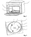
- FIG. 1 there is shown a perspective view of a microwave oven according to the invention.
- many components such as the furnace heating or ventilation means or its lighting are not shown or described here because they do not differ from devices well known to those skilled in the art and present on the current furnaces.
- the driving device comprises a means 7 providing a rotational torque to the turntable which in its inner part does not differ from the known devices and in its upper part engages with lugs located under the turntable 2 to ensure its training, so also known. It also comprises a removable wheel support 4 comprising the rotation axes 4 'of the wheels 5 on which the turntable 2 is placed. Said rotation axes 4 'are oriented radially with respect to the turntable 2.
- the drive device finally comprises bases 6 mounted on the removable wheel support 4, said bases 6 resting on the bottom 3 of the cavity of the microwave oven and ensuring the immobility of the removable wheel support 4 with respect to said cavity.
- These bases 6, mounted on the removable wheel support 4, are mounted free to rotate about the axes 4 'of said wheels 5, the center of gravity of said bases 6 being positioned so that the portion of said bases 6 revealing the wheels 5 is always on the top, regardless of the orientation of the removable wheel support 4.
- FIG 3 there is shown a sectional view of the drive device of the turntable 2 according to the invention. This view is based on the elements presented in the perspective view of the figure 1 .
- the bases 6 are housed in a circular stamp formed in the bottom 3 of the cavity of the microwave oven 1. This stamping is not essential but facilitates the positioning of the removable wheel support 4. In fact, the bases 6 coming to center naturally in this pressed, the positioning of the removable wheel support 4 is ensured.
- FIG. 4 a detail view of a wheel 5 of the device and of the base 6 associated with it is shown. There is also a part of the removable wheel support 4 and a wheel axis 4 'around which a base 6 is free to rotate.
- the removable wheel support 4 is metal and in the form of a circle on which are reported, for example by welding, the axes 4 '. But any other form could be envisaged such that a star having as many branches as wheels 5.
- the wheels 5 there must be at least three to provide a flat support for the turntable 2. It is possible to envisage more, but this has at least two disadvantages: a higher cost and risks of hyperstatism.
- the wheels 5 are made of Teflon to reduce friction and it is also possible to provide on the turntable 2 a tread (not shown) which is on the contact zone between the wheels 5 and the turntable 2.
- the wheels 5 are mounted on a groove of the axis 4 'whose diameter is smaller than that of the rest of the axis 4'. They are thus immobilized axially, but can rotate freely.
- the bases may be of any shape provided that they are mounted free to rotate about the axes 4 'of the wheels 5 and that their center of gravity is positioned opposite to the axis 4 ', the part of the wheels 5 they let appear.
- the bases 6 of the example illustrating the invention have a shape forming part of a parallelepiped.
- One of the faces, denominated superior in the following lines, of this parallelepiped is left open in order to let the wheel 5 which is housed inside the bases 6 pass.
- the side faces parallel to the two inner walls are also provided with notches.
- notches are designed so that the axis 4 'can not come out once inserted and that the only movement left to him is the rotation about the axis 4'.
- the angles between the lateral faces, parallel to the two inner walls, and the bottom face, opposite to the open face, are Lronques. This allows the base 6 to better adapt to the shape of the circular stamping made in the bottom 3 of the cavity of the microwave oven 1.
- the amount of material present above the zone of passage of the axis 4 ' is limited to the minimum necessary to position the center of gravity of the base 6 as low as possible, that is to say the further away from the open top.
- the natural position of the base will always face upwards, that is to say in the operating position, without the user having to choose a particular orientation for the removable wheel support 4.
- the invention responds to the concern of producing a drive device for a turntable microwave oven having the following advantages: a reduction of problems of jerk and slip related to the presence of foreign bodies between the wheels and the ferrule, a great ease of disassembly and ease of positioning thanks to its reversibility and ability to self-center.
Landscapes
- Physics & Mathematics (AREA)
- Electromagnetism (AREA)
- Electric Ovens (AREA)
- Constitution Of High-Frequency Heating (AREA)
- Handcart (AREA)
- Packaging Of Annular Or Rod-Shaped Articles, Wearing Apparel, Cassettes, Or The Like (AREA)
Description
- La présente invention se rapporte à un dispositif d'entraînement du plateau tournant d'un four à micro-ondes comprenant un moyen fournissant un couple de rotation au plateau tournant, au moins trois roues sur lesquelles le plateau tournant est posé et un support de roues amovible comprenant les axes de rotation desdites roues, lesdits axes étant orientés radialement par rapport au plateau.
- Les fours à micro-ondes connus sont généralement munis d'un plateau tournant destiné à recevoir un récipient ou assimilé contenant la nourriture à chauffer. Il existe principalement deux modes d'entraînement de ce plateau qui repose en général sur des roues liées à un support de roues.
- Dans le premier mode le couple fourni par un moteur est transmis directement au plateau- Le plateau entraîne alors dans son mouvement les roues sur lesquelles il repose et roule. Les roues, elles-mêmes, reposent et roulent sur le fond de la cavité du four à micro-ondes.
- Dans le second mode le couple fourni par un moteur est transmis au support de roues qui, par l'intermédiaire des roues, repose et roule sur le fond de la cavité du four à micro-ondes. La encore, deux types de conceptions sont rencontrées. Soit le plateau repose directement sur le support de roues et a un mouvement identique à celui dudit support. Soit le plateau, comme dans le premier mode, repose sur les roues qui en roulant sur ledit plateau l'entraînent en rotation à une vitesse deux fois plus élevée que celle du support de roues.
- Ces deux modes de réalisation présentent une contrainte commune: des corps étrangers peuvent venir se loger entre les roues et le fond de la cavité du four à micro-ondes, entraînant des à-coups dans le mouvement de rotation et/ou des patinages des roues.
- Une contrainte supplémentaire liée au second mode est celle de devoir positionner le support de roues dans un sens particulier, c'est-à-dire sur la bonne face, et de le positionner de façon à pouvoir l'accoupler correctement au moyen fournissant un couple de rotation au plateau tournant, par la mise en regard de deux méplats ou formes particulières d'entraînement.
- Par ailleurs, le document
US4590351 (D1) décrit un plateau tournant amovible disposant de son propre système d'entraînement pour s'adapter aux fours micro-ondes à sole fixe. Trois roues sont montées sur le pourtour de la base du plateau dans des zones en retrait. Les roues maintiennent le plateau en place et le laissent tourner. - Le but de l'invention est de proposer un support de roues qui se positionne naturellement quels que soient le sens et la position angulaire dans lesquels il est posé sur le fond de la cavité du four à micro-ondes. L'invention se propose d'utiliser un entraînement tel que le premier mode décrit ci-dessus, à savoir que le couple fourni par un moteur est transmis directement au plateau, celui-ci entraînant alors dans son mouvement les roues sur lesquelles il repose et roule.
- A cet effet, la présente invention concerne un dispositif d'entraînement du plateau tournant d'un four à micro-ondes comprenant un moyen fournissant un couple de rotation au plateau tournant, au moins trois roues sur lesquelles le plateau tournant est posé et un support de roues amovible comprenant les axes de rotation desdites roues, lesdits axes étant orientés radialement par rapport au plateau.
- Selon l'invention, le dispositif d'entraînement du plateau tournant comprend, en outre, des embases montées sur le support de roues amovible, lesdites embases reposant sur le fond, de la cavité du four à micro-ondes, lesdites embases assurant l'immobilité du support de roues amovible par rapport à ladite cavité, et les embases montées sur le support de roues amovible sont montées libres en rotation autour des axes desdites roues, le centre de gravité desdites embases étant positionné de telle sorte que la partie desdites embases laissant apparaître les roues se trouve toujours sur le dessus quelle que soit l'orientation du support de roues amovible.
- Ainsi, quel que soit le sens dans lequel le support de roues amovible est inséré dans la cavité du four à micro-ondes, il reposera toujours sur les embases et présentera les roues prêtes à recevoir le plateau tournant. L'invention élimine donc les dysfonctionnements liés à la présence de corps étrangers entre les roues et la virole.
- En outre, une conséquence intéressante de l'invention est qu'elle élimine les dysfonctionnements liés à un mauvais positionnement du support de roues.
- Une autre conséquence intéressante de ce dispositif est qu'il facilite le nettoyage de la cavité du four à micro-ondes puisque son retrait et sa mise en place sont faciles.
- Dans un mode de réalisation préféré de l'invention, les embases viennent se positionner dans un embouti circulaire réalisé dans le fond de la cavité du four à micro-ondes.
Idéalement, le diamètre de l'embouti circulaire réalisé dans le fond de la cavité du four à micro-ondes est identique à celui de la bande de roulement circulaire spécifique présente sur les plateaux tournants standard et sur laquelle viennent rouler les roues 5. - Ainsi le mouvement de rotation du plateau tournant est optimisé.
- D'autres caractéristiques et avantages de l'invention ressortiront de la description qui va suivre, donnée à titre d'exemple non limitatif, en référence aux dessins annexés dans lesquels :
- La
figure 1 est une vue en perspective d'un four à micro-ondes selon l'invention ; - La
figure 2 est une vue en perspective du fond de la cavité d'un four à micro-ondes selon l'invention; - La
figure 3 est une vue en coupe du dispositif d'entraînement du plateau tournant selon l'invention ; et - La
figure 4 est une vue de détail d'une roue du dispositif et de l'embase qui lui est associée. - A la
figure 1 on a représenté une vue en perspective d'un four à micro-ondes selon l'invention. Bien entendu, de nombreux composants tels que les moyens de chauffage ou de ventilation du four ou encore son éclairage ne sont pas représentés ni décrits ici car ils ne différent pas des dispositifs bien connus de l'homme de l'art et présents sur les fours actuels. - A la
figure 2 on a représenté une vue en perspective d'un four à micro-ondes selon l'invention. Cette vue permet de bien visualiser les différents composants qui interviendront dans la description qui va suivre. On a donc représenté le fond 3 de la cavité du four à micro-ondes 1 où est disposé un plateau tournant 2.
Le dispositif d'entraînement comprend un moyen 7 fournissant un couple de rotation au plateau tournant qui dans sa partie intérieure ne diffère pas des dispositifs connus et dans sa partie supérieure vient en prise avec des ergots situés sous le plateau tournant 2 afin d'assurer son entraînement, de façon elle aussi connue.
Il comprend aussi un support de roues amovible 4 comprenant les axes de rotation 4' des roues 5 sur lesquelles le plateau tournant 2 est posé. Lesdits axes de rotation 4' sont orientés radialement par rapport au plateau tournant 2.
Le dispositif d'entraînement comprend enfin des embases 6 montées sur le support de roues amovible 4, lesdites embases 6 reposant sur le fond 3 de la cavité du four à micro-ondes et assurant l'immobilité du support de roues amovible 4 par rapport à ladite cavité.
Ces embases 6, montées sur le support de roues amovible 4, sont montées libres en rotation autour des axes 4' desdites roues 5, le centre de gravité desdites embases 6 étant positionné de telle sorte que la partie desdites embases 6 laissant apparaître les roues 5 se trouve toujours sur le dessus, quelle que soit l'orientation du support de roues amovible 4. - A la
figure 3 on a représenté une vue en coupe du dispositif d'entraînement du plateau tournant 2 selon l'invention. Cette vue reprend les éléments présentés dans la vue en perspective de lafigure 1 . On remarque que selon une caractéristique préférée de l'invention, les embases 6 viennent se loger dans un embouti circulaire réalisé dans le fond 3 de la cavité du four à micro-ondes 1. Cet embouti n'est pas indispensable mais facilite le positionnement du support de roues amovible 4. En effet, les embases 6 venant se centrer naturellement dans cet embouti, le positionnement du support de roues amovible 4 est assuré. - Enfin, à la
figure 4 on a représenté une vue de détail d'une roue 5 du dispositif et de l'embase 6 qui lui est associée. On distingue de plus une partie du support de roues amovible 4 et un axe 4' de roue 5 autour duquel est monté libre en rotation une embase 6. - Selon une caractéristique préférée de l'invention, le support de roues amovible 4 est métallique et en forme de cercle sur lequel sont rapportés, par soudure par exemple, les axes 4'. Mais toute autre forme pourrait être envisagée telle qu'une étoile comportant autant de branches que de roues 5.
- En ce qui concerne les roues 5, elles doivent être au nombre de trois au minimum pour assurer un appui plan pour les plateau tournant 2. Il est envisageable d'en prévoir plus, mais cela présente au moins deux inconvénients : un coût plus élevé et des risques d'hyperstatisme. Idéalement, les roues 5 sont réalisées en Téflon afin de réduire les frottements et il est, de plus, possible de prévoir sur le plateau tournant 2 une bande de roulement (non représentée) qui se trouve sur la zone de contact entre les roues 5 et le plateau tournant 2. Les roues 5 sont montées sur une gorge de l'axe 4' dont le diamètre est plus faible que celui du reste de l'axe 4'. Elles sont ainsi immobilisée axialement, mais peuvent tourner librement.
- Enfin, les embases peuvent être de forme quelconque à condition de respecter le fait qu'elles soient montées libres en rotation autour des axes 4' des roues 5 et que leur centre de gravité soit positionné à l'opposé, par rapport à l'axe 4', de la partie des roues 5 qu'elles laissent apparaître.
Les embases 6 de l'exemple illustrant l'invention ont une forme s'inscrivant dans un parallélépipède. - Une des faces, dénommée supérieure dans les lignes qui suivent, de ce parallélépipède est laissée ouverte afin de laisser dépasser la roue 5 qui vient se loger à l'intérieur des embases 6.
Deux parois internes, parallèles entre elles et à deux des faces latérales du parallélépipède et perpendiculaires à la face supérieure ouverte de ce dernier, entourent la roue. Elles sont munies chacune d'une encoche de largeur supérieure au diamètre de l'axe 4' dans laquelle est inséré ledit axe 4'. Ces parois permettent de positionner axialement l'embase 6 sur l'axe 4' par l'intermédiaire des roues 5.
Les faces latérales parallèles aux deux parois internes sont, elles aussi, munies d'encoches. Ces encoches sont conçues de telle façon que l'axe 4' ne peut pas en ressortir une fois inséré et que le seul mouvement qui lui est alors laissé est la rotation autour de l'axe 4'.
D'autre part, les angles entre les faces latérales, parallèles aux deux parois internes, et la face du dessous, opposée à la face ouverte, sont Lronqués. Cela permet à l'embase 6 de mieux s'adapter à la forme de l'embouti circulaire réalisé dans le fond 3 de la cavité du four à micro-ondes 1.
Enfin, la quantité de matière présente au dessus de la zone de passage de l'axe 4' est limitée au minimum nécessaire afin de positionner le centre de gravité de l'embase 6 le plus bas possible, c'est-à-dire le plus loin possible de la face supérieure ouverte. Ainsi la position naturelle de l'embase sera toujours face ouverte vers le haut, c'est-à-dire en position de fonctionnement, sans que l'utilisateur n'ait à choisir une orientation particulière pour le support de roues amovible 4. - L'invention répond au souci de réaliser un dispositif d'entraînement d'un plateau tournant de four à micro-ondes présentant avantages suivants : une réduction des problèmes d'à-coup et de patinage liés à la présence de corps étrangers entre les roues et la virole, une grande facilité de démontage et une facilité de mise en position grâce à sa réversibilité et à sa capacité d'auto-centrage.
Claims (6)
- Dispositif d'entraînement du plateau tournant (2) d'un four à micro-ondes (1) comprenant un moyen (7) fournissant un couple de rotation au plateau tournant (2), au moins trois roues (5) sur lesquelles le plateau tournant (2) est posé et un support de roues amovible (4) comprenant les axes (4') de rotation desdites roues (5), lesdits axes (4') étant orientés radialement par rapport au plateau (2),
caractérisé en ce qu'il comprend, en outre, des embases (6) montées sur le support de roues amovible (4), lesdites embases (6) reposant sur le fond (3) de la cavité du four à micro-ondes (1), lesdites embases assurant l'immobilité du support de roues amovible (4) par rapport à ladite cavité, et en ce que les embases (6) montées sur le support de roues amovible (4) sont montées libres en rotation autour des axes (4') desdites roues (5), le centre de gravité desdites embases (6) étant positionné de telle sorte que la partie desdites embases (6) laissant apparaître les roues (5) se trouve toujours sur le dessus quelle que soit l'orientation du support de roues amovible (4). - Dispositif d'entrainement du plateau tournant s'un four à micro-ondes selon la revendication 1,
Caractérisé en ce que lesdites embases (6) sont adaptées à venir se positionner dans un embouti circulaire réalisé dans le fond (3) de la cavité du four à micro-ondes (1). - Dispositif d'entraînement du plateau tournant d'un four à micro-ondes selon la revendication 2,
caractérisé en ce que le diamètre de l'embouti circulaire réalisé dans le fond (3) de la cavité du four à micro-ondes (1) est identique à celui de la bande de roulement circulaire spécifique présente sur les plateaux tournants standard et sur laquelle viennent rouler les roues (5). - Dispositif d'entraînement du plateau tournant d'un four à micro-ondes selon l'une des revendications précédentes,
caractérisé en ce que les roues (5) sont montées sur une gorge de l'axe (4'). - Dispositif d'entraînement du plateau tournant d'un four à micro-ondes selon l'une des revendications précédentes,
caractérisé en ce que les embases (6) ont une forma s'inscrivant dans un parallélépipède. - Dispositif d'entraînement du plateau tournant d'un four à micro-ondes selon l'une des revendications précédentes,
caractérisé en ce que les angles entre les faces latérales et la face opposée à la face ouverte de l'embase (6) sont tronqués.
Priority Applications (1)
| Application Number | Priority Date | Filing Date | Title |
|---|---|---|---|
| PL05013539T PL1610592T3 (pl) | 2004-06-25 | 2005-06-23 | Urządzenie do napędzania obrotowej płyty kuchenki mikrofalowej wyposażonej w zdejmowalną podporę kółek |
Applications Claiming Priority (2)
| Application Number | Priority Date | Filing Date | Title |
|---|---|---|---|
| FR0406965 | 2004-06-25 | ||
| FR0406965A FR2872259B1 (fr) | 2004-06-25 | 2004-06-25 | Dispositif d'entrainement du plateau tournant d'un four a micro-ondes muni d'un support de roues amovible |
Publications (3)
| Publication Number | Publication Date |
|---|---|
| EP1610592A2 EP1610592A2 (fr) | 2005-12-28 |
| EP1610592A3 EP1610592A3 (fr) | 2006-02-01 |
| EP1610592B1 true EP1610592B1 (fr) | 2010-01-06 |
Family
ID=34945661
Family Applications (1)
| Application Number | Title | Priority Date | Filing Date |
|---|---|---|---|
| EP05013539A Expired - Lifetime EP1610592B1 (fr) | 2004-06-25 | 2005-06-23 | Dispositif d'entrainement du plateau tournant d'un four a micro-ondes muni d'un support de roues amovible |
Country Status (6)
| Country | Link |
|---|---|
| EP (1) | EP1610592B1 (fr) |
| AT (1) | ATE454805T1 (fr) |
| DE (1) | DE602005018714D1 (fr) |
| ES (1) | ES2339121T3 (fr) |
| FR (1) | FR2872259B1 (fr) |
| PL (1) | PL1610592T3 (fr) |
Families Citing this family (2)
| Publication number | Priority date | Publication date | Assignee | Title |
|---|---|---|---|---|
| CN109605006B (zh) * | 2018-12-26 | 2020-08-25 | 珠海市明明机器人科技有限公司 | 一种微波炉的转轮装配机构 |
| CN110631062B (zh) * | 2019-10-22 | 2020-11-06 | 广东美的厨房电器制造有限公司 | 烹饪器具 |
Family Cites Families (4)
| Publication number | Priority date | Publication date | Assignee | Title |
|---|---|---|---|---|
| JPS6051007B2 (ja) * | 1982-03-19 | 1985-11-12 | 株式会社東芝 | 高周波加熱調理装置 |
| JPS6030081A (ja) * | 1983-07-28 | 1985-02-15 | シャープ株式会社 | 電子レンジのタ−ンテ−ブル駆動構造 |
| US4590351A (en) * | 1985-03-22 | 1986-05-20 | Plastics, Inc. | Compact portable turntable for microwave ovens |
| KR100385045B1 (ko) * | 1999-09-22 | 2003-05-22 | 삼성전자주식회사 | 전자렌지 |
-
2004
- 2004-06-25 FR FR0406965A patent/FR2872259B1/fr not_active Expired - Fee Related
-
2005
- 2005-06-23 DE DE602005018714T patent/DE602005018714D1/de not_active Expired - Lifetime
- 2005-06-23 ES ES05013539T patent/ES2339121T3/es not_active Expired - Lifetime
- 2005-06-23 PL PL05013539T patent/PL1610592T3/pl unknown
- 2005-06-23 AT AT05013539T patent/ATE454805T1/de not_active IP Right Cessation
- 2005-06-23 EP EP05013539A patent/EP1610592B1/fr not_active Expired - Lifetime
Also Published As
| Publication number | Publication date |
|---|---|
| ES2339121T3 (es) | 2010-05-17 |
| FR2872259A1 (fr) | 2005-12-30 |
| DE602005018714D1 (de) | 2010-02-25 |
| EP1610592A3 (fr) | 2006-02-01 |
| PL1610592T3 (pl) | 2010-06-30 |
| ATE454805T1 (de) | 2010-01-15 |
| EP1610592A2 (fr) | 2005-12-28 |
| FR2872259B1 (fr) | 2007-02-09 |
Similar Documents
| Publication | Publication Date | Title |
|---|---|---|
| EP0034073B1 (fr) | Perfectionnements aux joints universels | |
| FR3014143A1 (fr) | Unite de soupape, telle qu'une unite de clapet d'echappement pour vehicules automobiles | |
| EP2585576B1 (fr) | Boite de petri comportant des moyens de verrouillage en vue de la constitution d'une pile | |
| WO2005002889A2 (fr) | Ensemble d’articulation d’attelage a amortissement des mouvements de lacet d’une remorque | |
| FR2956623A1 (fr) | Dispositif de reglage angulaire pour siege de vehicule | |
| FR2479939A1 (fr) | Engrenages planetaires du type a rouleaux ayant un agencement de prechargement | |
| FR2619429A1 (fr) | Coupleur hydraulique utilisable notamment comme differentiel entre les essieux avant et arriere d'un vehicule automobile | |
| EP1610592A2 (fr) | Dispositif d'entrainement du plateau tournant d'un four a micro-ondes muni d'un support de roues amovible | |
| FR2740372A1 (fr) | Outil d'installation et d'alignement d'un chapeau de palier pour joint de cardan | |
| EP0013719A1 (fr) | Roue d'impression à languettes porte-caractères radiales, destinée à être contenue dans une cartouche | |
| EP2300243B1 (fr) | Dispositif de fixtion d'un roulement a un axe | |
| EP2909509B1 (fr) | Dispositif différentiel pour engin roulant motorisé | |
| EP0013346A1 (fr) | Cartouche pour roue d'impression à languettes porte-caractères radiales | |
| FR2995375A1 (fr) | Butee d'embrayage-debrayage et vehicule automobile equipe d'une telle butee | |
| EP1072811A1 (fr) | Dispositif de maintien de deux joncs d'armement dans un moyeu de synchronisation pouvant être utilisé dans un ensemble synchroniseur pour une transmission d'un véhicule automobile | |
| EP1626891A1 (fr) | DISPOSITIF DE FIXATION D’UNE ROUE DE VELO SUR UN CADRE | |
| WO2021151646A1 (fr) | Essuyage pour petite surface | |
| EP0366563A1 (fr) | Différentiel autobloquant | |
| FR2694796A1 (fr) | Embrayage visqueux. | |
| EP1935302A1 (fr) | Boite de rangement pour mixeur menager de type plongeant | |
| EP3839285A1 (fr) | Dispositif de transmission de couple à plusieurs embrayages multidisques actionnés par fluide | |
| FR3115578A1 (fr) | Dispositif d’embrayage unidirectionnel | |
| EP2039613A1 (fr) | Organe de calage d'un appareil de cuisson comportant une cuve et un couvercle et emballage comprenant un tel organe | |
| EP3912525B1 (fr) | Appareil de cuisson d'aliments comprenant une cuve de cuisson amovible | |
| FR3154694A1 (fr) | Dispositif de changement de vitesse et engin de mobilité associé. |
Legal Events
| Date | Code | Title | Description |
|---|---|---|---|
| PUAI | Public reference made under article 153(3) epc to a published international application that has entered the european phase |
Free format text: ORIGINAL CODE: 0009012 |
|
| PUAL | Search report despatched |
Free format text: ORIGINAL CODE: 0009013 |
|
| AK | Designated contracting states |
Kind code of ref document: A2 Designated state(s): AT BE BG CH CY CZ DE DK EE ES FI FR GB GR HU IE IS IT LI LT LU MC NL PL PT RO SE SI SK TR |
|
| AX | Request for extension of the european patent |
Extension state: AL BA HR LV MK YU |
|
| AK | Designated contracting states |
Kind code of ref document: A3 Designated state(s): AT BE BG CH CY CZ DE DK EE ES FI FR GB GR HU IE IS IT LI LT LU MC NL PL PT RO SE SI SK TR |
|
| AX | Request for extension of the european patent |
Extension state: AL BA HR LV MK YU |
|
| RTI1 | Title (correction) |
Free format text: DRIVE DEVICE FOR A TURNTABLE IN A MICROWAVE OVEN HAVING A REMOVABLE WHEEL SUPPORT ASSEMBLY |
|
| 17P | Request for examination filed |
Effective date: 20060513 |
|
| AKX | Designation fees paid |
Designated state(s): AT BE BG CH CY CZ DE DK EE ES FI FR GB GR HU IE IS IT LI LT LU MC NL PL PT RO SE SI SK TR |
|
| 17Q | First examination report despatched |
Effective date: 20060624 |
|
| RAP1 | Party data changed (applicant data changed or rights of an application transferred) |
Owner name: FAGORBRANDT SAS |
|
| GRAP | Despatch of communication of intention to grant a patent |
Free format text: ORIGINAL CODE: EPIDOSNIGR1 |
|
| GRAS | Grant fee paid |
Free format text: ORIGINAL CODE: EPIDOSNIGR3 |
|
| GRAA | (expected) grant |
Free format text: ORIGINAL CODE: 0009210 |
|
| AK | Designated contracting states |
Kind code of ref document: B1 Designated state(s): AT BE BG CH CY CZ DE DK EE ES FI FR GB GR HU IE IS IT LI LT LU MC NL PL PT RO SE SI SK TR |
|
| REG | Reference to a national code |
Ref country code: GB Ref legal event code: FG4D Free format text: NOT ENGLISH |
|
| REG | Reference to a national code |
Ref country code: CH Ref legal event code: EP |
|
| REG | Reference to a national code |
Ref country code: IE Ref legal event code: FG4D |
|
| REF | Corresponds to: |
Ref document number: 602005018714 Country of ref document: DE Date of ref document: 20100225 Kind code of ref document: P |
|
| REG | Reference to a national code |
Ref country code: NL Ref legal event code: VDEP Effective date: 20100106 |
|
| REG | Reference to a national code |
Ref country code: ES Ref legal event code: FG2A Ref document number: 2339121 Country of ref document: ES Kind code of ref document: T3 |
|
| PG25 | Lapsed in a contracting state [announced via postgrant information from national office to epo] |
Ref country code: SI Free format text: LAPSE BECAUSE OF FAILURE TO SUBMIT A TRANSLATION OF THE DESCRIPTION OR TO PAY THE FEE WITHIN THE PRESCRIBED TIME-LIMIT Effective date: 20100106 |
|
| LTIE | Lt: invalidation of european patent or patent extension |
Effective date: 20100106 |
|
| PG25 | Lapsed in a contracting state [announced via postgrant information from national office to epo] |
Ref country code: AT Free format text: LAPSE BECAUSE OF FAILURE TO SUBMIT A TRANSLATION OF THE DESCRIPTION OR TO PAY THE FEE WITHIN THE PRESCRIBED TIME-LIMIT Effective date: 20100106 |
|
| PG25 | Lapsed in a contracting state [announced via postgrant information from national office to epo] |
Ref country code: PT Free format text: LAPSE BECAUSE OF FAILURE TO SUBMIT A TRANSLATION OF THE DESCRIPTION OR TO PAY THE FEE WITHIN THE PRESCRIBED TIME-LIMIT Effective date: 20100506 Ref country code: NL Free format text: LAPSE BECAUSE OF FAILURE TO SUBMIT A TRANSLATION OF THE DESCRIPTION OR TO PAY THE FEE WITHIN THE PRESCRIBED TIME-LIMIT Effective date: 20100106 Ref country code: IS Free format text: LAPSE BECAUSE OF FAILURE TO SUBMIT A TRANSLATION OF THE DESCRIPTION OR TO PAY THE FEE WITHIN THE PRESCRIBED TIME-LIMIT Effective date: 20100506 Ref country code: LT Free format text: LAPSE BECAUSE OF FAILURE TO SUBMIT A TRANSLATION OF THE DESCRIPTION OR TO PAY THE FEE WITHIN THE PRESCRIBED TIME-LIMIT Effective date: 20100106 |
|
| REG | Reference to a national code |
Ref country code: IE Ref legal event code: FD4D |
|
| PG25 | Lapsed in a contracting state [announced via postgrant information from national office to epo] |
Ref country code: FI Free format text: LAPSE BECAUSE OF FAILURE TO SUBMIT A TRANSLATION OF THE DESCRIPTION OR TO PAY THE FEE WITHIN THE PRESCRIBED TIME-LIMIT Effective date: 20100106 |
|
| PG25 | Lapsed in a contracting state [announced via postgrant information from national office to epo] |
Ref country code: GR Free format text: LAPSE BECAUSE OF FAILURE TO SUBMIT A TRANSLATION OF THE DESCRIPTION OR TO PAY THE FEE WITHIN THE PRESCRIBED TIME-LIMIT Effective date: 20100407 Ref country code: EE Free format text: LAPSE BECAUSE OF FAILURE TO SUBMIT A TRANSLATION OF THE DESCRIPTION OR TO PAY THE FEE WITHIN THE PRESCRIBED TIME-LIMIT Effective date: 20100106 Ref country code: CY Free format text: LAPSE BECAUSE OF FAILURE TO SUBMIT A TRANSLATION OF THE DESCRIPTION OR TO PAY THE FEE WITHIN THE PRESCRIBED TIME-LIMIT Effective date: 20100106 Ref country code: SE Free format text: LAPSE BECAUSE OF FAILURE TO SUBMIT A TRANSLATION OF THE DESCRIPTION OR TO PAY THE FEE WITHIN THE PRESCRIBED TIME-LIMIT Effective date: 20100106 Ref country code: RO Free format text: LAPSE BECAUSE OF FAILURE TO SUBMIT A TRANSLATION OF THE DESCRIPTION OR TO PAY THE FEE WITHIN THE PRESCRIBED TIME-LIMIT Effective date: 20100106 Ref country code: IE Free format text: LAPSE BECAUSE OF FAILURE TO SUBMIT A TRANSLATION OF THE DESCRIPTION OR TO PAY THE FEE WITHIN THE PRESCRIBED TIME-LIMIT Effective date: 20100106 |
|
| PLBE | No opposition filed within time limit |
Free format text: ORIGINAL CODE: 0009261 |
|
| STAA | Information on the status of an ep patent application or granted ep patent |
Free format text: STATUS: NO OPPOSITION FILED WITHIN TIME LIMIT |
|
| PG25 | Lapsed in a contracting state [announced via postgrant information from national office to epo] |
Ref country code: CZ Free format text: LAPSE BECAUSE OF FAILURE TO SUBMIT A TRANSLATION OF THE DESCRIPTION OR TO PAY THE FEE WITHIN THE PRESCRIBED TIME-LIMIT Effective date: 20100106 Ref country code: SK Free format text: LAPSE BECAUSE OF FAILURE TO SUBMIT A TRANSLATION OF THE DESCRIPTION OR TO PAY THE FEE WITHIN THE PRESCRIBED TIME-LIMIT Effective date: 20100106 Ref country code: BG Free format text: LAPSE BECAUSE OF FAILURE TO SUBMIT A TRANSLATION OF THE DESCRIPTION OR TO PAY THE FEE WITHIN THE PRESCRIBED TIME-LIMIT Effective date: 20100406 |
|
| 26N | No opposition filed |
Effective date: 20101007 |
|
| BERE | Be: lapsed |
Owner name: FAGORBRANDT SAS Effective date: 20100630 |
|
| PG25 | Lapsed in a contracting state [announced via postgrant information from national office to epo] |
Ref country code: DK Free format text: LAPSE BECAUSE OF FAILURE TO SUBMIT A TRANSLATION OF THE DESCRIPTION OR TO PAY THE FEE WITHIN THE PRESCRIBED TIME-LIMIT Effective date: 20100106 Ref country code: MC Free format text: LAPSE BECAUSE OF NON-PAYMENT OF DUE FEES Effective date: 20100630 |
|
| REG | Reference to a national code |
Ref country code: CH Ref legal event code: PL |
|
| GBPC | Gb: european patent ceased through non-payment of renewal fee |
Effective date: 20100623 |
|
| PG25 | Lapsed in a contracting state [announced via postgrant information from national office to epo] |
Ref country code: LI Free format text: LAPSE BECAUSE OF NON-PAYMENT OF DUE FEES Effective date: 20100630 Ref country code: CH Free format text: LAPSE BECAUSE OF NON-PAYMENT OF DUE FEES Effective date: 20100630 |
|
| PG25 | Lapsed in a contracting state [announced via postgrant information from national office to epo] |
Ref country code: BE Free format text: LAPSE BECAUSE OF NON-PAYMENT OF DUE FEES Effective date: 20100630 |
|
| PG25 | Lapsed in a contracting state [announced via postgrant information from national office to epo] |
Ref country code: GB Free format text: LAPSE BECAUSE OF NON-PAYMENT OF DUE FEES Effective date: 20100623 |
|
| PG25 | Lapsed in a contracting state [announced via postgrant information from national office to epo] |
Ref country code: LU Free format text: LAPSE BECAUSE OF NON-PAYMENT OF DUE FEES Effective date: 20100623 Ref country code: HU Free format text: LAPSE BECAUSE OF FAILURE TO SUBMIT A TRANSLATION OF THE DESCRIPTION OR TO PAY THE FEE WITHIN THE PRESCRIBED TIME-LIMIT Effective date: 20100707 |
|
| PG25 | Lapsed in a contracting state [announced via postgrant information from national office to epo] |
Ref country code: TR Free format text: LAPSE BECAUSE OF FAILURE TO SUBMIT A TRANSLATION OF THE DESCRIPTION OR TO PAY THE FEE WITHIN THE PRESCRIBED TIME-LIMIT Effective date: 20100106 |
|
| REG | Reference to a national code |
Ref country code: FR Ref legal event code: CA Effective date: 20130605 |
|
| REG | Reference to a national code |
Ref country code: FR Ref legal event code: PLFP Year of fee payment: 11 |
|
| REG | Reference to a national code |
Ref country code: ES Ref legal event code: PC2A Owner name: GROUPE BRANDT Effective date: 20150716 |
|
| PGFP | Annual fee paid to national office [announced via postgrant information from national office to epo] |
Ref country code: PL Payment date: 20150429 Year of fee payment: 11 |
|
| REG | Reference to a national code |
Ref country code: FR Ref legal event code: TP Owner name: GROUPE BRANDT, FR Effective date: 20150818 |
|
| REG | Reference to a national code |
Ref country code: DE Ref legal event code: R081 Ref document number: 602005018714 Country of ref document: DE Owner name: GROUPE BRANDT, FR Free format text: FORMER OWNER: FAGORBRANDT SAS, RUEIL-MALMAISON, FR |
|
| REG | Reference to a national code |
Ref country code: FR Ref legal event code: GC Effective date: 20151013 |
|
| REG | Reference to a national code |
Ref country code: FR Ref legal event code: PLFP Year of fee payment: 12 |
|
| PGFP | Annual fee paid to national office [announced via postgrant information from national office to epo] |
Ref country code: ES Payment date: 20160616 Year of fee payment: 12 |
|
| PGFP | Annual fee paid to national office [announced via postgrant information from national office to epo] |
Ref country code: IT Payment date: 20160608 Year of fee payment: 12 |
|
| PGFP | Annual fee paid to national office [announced via postgrant information from national office to epo] |
Ref country code: DE Payment date: 20160630 Year of fee payment: 12 |
|
| REG | Reference to a national code |
Ref country code: FR Ref legal event code: PLFP Year of fee payment: 13 |
|
| PG25 | Lapsed in a contracting state [announced via postgrant information from national office to epo] |
Ref country code: PL Free format text: LAPSE BECAUSE OF NON-PAYMENT OF DUE FEES Effective date: 20160623 |
|
| REG | Reference to a national code |
Ref country code: DE Ref legal event code: R119 Ref document number: 602005018714 Country of ref document: DE |
|
| PG25 | Lapsed in a contracting state [announced via postgrant information from national office to epo] |
Ref country code: DE Free format text: LAPSE BECAUSE OF NON-PAYMENT OF DUE FEES Effective date: 20180103 |
|
| PG25 | Lapsed in a contracting state [announced via postgrant information from national office to epo] |
Ref country code: IT Free format text: LAPSE BECAUSE OF NON-PAYMENT OF DUE FEES Effective date: 20170623 |
|
| REG | Reference to a national code |
Ref country code: FR Ref legal event code: PLFP Year of fee payment: 14 |
|
| REG | Reference to a national code |
Ref country code: ES Ref legal event code: FD2A Effective date: 20181112 |
|
| PG25 | Lapsed in a contracting state [announced via postgrant information from national office to epo] |
Ref country code: ES Free format text: LAPSE BECAUSE OF NON-PAYMENT OF DUE FEES Effective date: 20170624 |
|
| PGFP | Annual fee paid to national office [announced via postgrant information from national office to epo] |
Ref country code: FR Payment date: 20210618 Year of fee payment: 17 |
|
| PG25 | Lapsed in a contracting state [announced via postgrant information from national office to epo] |
Ref country code: FR Free format text: LAPSE BECAUSE OF NON-PAYMENT OF DUE FEES Effective date: 20220630 |