EP1610107A1 - Variable high speed shutter for spectroradiometry - Google Patents
Variable high speed shutter for spectroradiometry Download PDFInfo
- Publication number
- EP1610107A1 EP1610107A1 EP05253101A EP05253101A EP1610107A1 EP 1610107 A1 EP1610107 A1 EP 1610107A1 EP 05253101 A EP05253101 A EP 05253101A EP 05253101 A EP05253101 A EP 05253101A EP 1610107 A1 EP1610107 A1 EP 1610107A1
- Authority
- EP
- European Patent Office
- Prior art keywords
- pulse
- radiation
- timer
- sampling
- duration
- Prior art date
- Legal status (The legal status is an assumption and is not a legal conclusion. Google has not performed a legal analysis and makes no representation as to the accuracy of the status listed.)
- Granted
Links
Images
Classifications
-
- G—PHYSICS
- G01—MEASURING; TESTING
- G01J—MEASUREMENT OF INTENSITY, VELOCITY, SPECTRAL CONTENT, POLARISATION, PHASE OR PULSE CHARACTERISTICS OF INFRARED, VISIBLE OR ULTRAVIOLET LIGHT; COLORIMETRY; RADIATION PYROMETRY
- G01J3/00—Spectrometry; Spectrophotometry; Monochromators; Measuring colours
- G01J3/02—Details
-
- G—PHYSICS
- G01—MEASURING; TESTING
- G01J—MEASUREMENT OF INTENSITY, VELOCITY, SPECTRAL CONTENT, POLARISATION, PHASE OR PULSE CHARACTERISTICS OF INFRARED, VISIBLE OR ULTRAVIOLET LIGHT; COLORIMETRY; RADIATION PYROMETRY
- G01J3/00—Spectrometry; Spectrophotometry; Monochromators; Measuring colours
- G01J3/02—Details
- G01J3/0205—Optical elements not provided otherwise, e.g. optical manifolds, diffusers, windows
- G01J3/021—Optical elements not provided otherwise, e.g. optical manifolds, diffusers, windows using plane or convex mirrors, parallel phase plates, or particular reflectors
-
- G—PHYSICS
- G01—MEASURING; TESTING
- G01J—MEASUREMENT OF INTENSITY, VELOCITY, SPECTRAL CONTENT, POLARISATION, PHASE OR PULSE CHARACTERISTICS OF INFRARED, VISIBLE OR ULTRAVIOLET LIGHT; COLORIMETRY; RADIATION PYROMETRY
- G01J3/00—Spectrometry; Spectrophotometry; Monochromators; Measuring colours
- G01J3/02—Details
- G01J3/0205—Optical elements not provided otherwise, e.g. optical manifolds, diffusers, windows
- G01J3/0232—Optical elements not provided otherwise, e.g. optical manifolds, diffusers, windows using shutters
-
- G—PHYSICS
- G01—MEASURING; TESTING
- G01J—MEASUREMENT OF INTENSITY, VELOCITY, SPECTRAL CONTENT, POLARISATION, PHASE OR PULSE CHARACTERISTICS OF INFRARED, VISIBLE OR ULTRAVIOLET LIGHT; COLORIMETRY; RADIATION PYROMETRY
- G01J5/00—Radiation pyrometry, e.g. infrared or optical thermometry
- G01J5/02—Constructional details
- G01J5/08—Optical arrangements
- G01J5/0803—Arrangements for time-dependent attenuation of radiation signals
- G01J5/0805—Means for chopping radiation
-
- G—PHYSICS
- G02—OPTICS
- G02B—OPTICAL ELEMENTS, SYSTEMS OR APPARATUS
- G02B26/00—Optical devices or arrangements for the control of light using movable or deformable optical elements
- G02B26/08—Optical devices or arrangements for the control of light using movable or deformable optical elements for controlling the direction of light
- G02B26/0816—Optical devices or arrangements for the control of light using movable or deformable optical elements for controlling the direction of light by means of one or more reflecting elements
- G02B26/0825—Optical devices or arrangements for the control of light using movable or deformable optical elements for controlling the direction of light by means of one or more reflecting elements the reflecting element being a flexible sheet or membrane, e.g. for varying the focus
Definitions
- This invention relates generally to spectroradiometry and, more particularly, to techniques for selecting a desired sample of radiation for analysis in a spectroradiometer.
- spectroradiometry is the spectral analysis of radiation received from a radiation source.
- the present invention is principally concerned with spectroradiometry as applied in the spectral analysis of radiation emitted from a solar radiation simulator.
- Solar simulators are used to evaluate the performance of solar panels. Rather than exposing solar panels to sunlight, which may be impractical if the panels are to be deployed in space, a solar simulator is designed to generate a brief flash of radiation with a spectral content closely approximating that of the sun. Obviously, using a pulse of simulated radiation for this purpose requires less total energy that if a continuously operating simulator were used, and permits the use of components and conductors rated for much lower powers.
- a solar simulator is to be relied on in the testing of solar panels, the spectral content of the radiation generated by the solar simulator is of significant interest.
- what is of interest to solar panel designers is the spectral content of a solar simulator flash as recorded over a time interval that corresponds to the time interval of the flash used to evaluate solar panel performance.
- the spectral content of a flash of radiation from a solar simulator is known to vary with time as the energy of the flash builds to a plateau, and later decays.
- a solar simulator typically provides no warning signal before it begins to produce a flash of output radiation, and yet spectral analysis of the flash must ideally be performed only over a narrow time interval at the same region of the flash of energy that is used in evaluating the solar panel or panels.
- the apparatus of the invention comprises an optical detector for sensing initiation of a pulse of radiation; timing electronics for producing a control pulse or a desired duration less than the duration of the pulse of radiation, and starting at a desired delay time after sensing of initiation of the pulse of radiation; and a mirror assembly comprising a deformable mirror that is aligned to receive the pulse of radiation, and that is responsive to the control pulse to assume a fully reflective state for the duration of the control pulse.
- the deformable mirror when in the fully reflective state reflects the pulse of radiation into a spectroradiometer for further processing.
- the deformable mirror when not in the fully reflective state prevents further processing or analysis of the pulse of radiation.
- the deformable mirror is an electrically actuated deformable membrane mirror, which is controllable to switch rapidly between a generally planar, undistorted state and a deformed state in which the mirror diffuses light impinging on it.
- the timing electronics may comprise a first timer and a second timer.
- the first timer is triggered by a signal from the optical detector upon sensing initiation of the pulse of radiation, and the first timer generates an output signal when a selected delay time has elapsed after the initiation of the pulse of radiation.
- the second timer is triggered by the output signal from the first timer, and generates the control pulse applied to the mirror.
- the first timer further comprises means for selecting the delay time; and the second timer further comprises means for selecting the duration of the control pulse.
- the timing electronics may further comprise a comparator, for comparing the signal from the optical detector with a threshold level; and means for selecting the threshold level.
- the invention may also be defined in terms of a method for sampling a pulse of radiation, comprising the steps of sensing the beginning of the pulse of radiation; triggering, in response to the sensing step, operation of a first timer, to measure a desired delay before sampling the pulse of radiation; and triggering a second timer in response to operation of the first timer, to generate a sampling pulse starting at a time determined by the first timer and having a duration determined by the second timer.
- the method further comprises applying the sampling pulse to control a deformable mirror and thereby switching the deformable mirror to a fully reflective state for the duration of the sampling pulse; and reflecting the pulse of radiation into a radiation measurement instrument when the deformable mirror is in the fully reflective state, to perform spectral analysis of the pulse of radiation during the time of the selected sampling pulse.
- the sensing step comprises generating an electrical signal from incident radiation received in the pulse of radiation; comparing the electrical signal with a threshold signal; and generating a triggering signal and applying it to the first timer when the electrical signal exceeds the threshold signal.
- the sensing step may further comprise varying the threshold signal to obtain a desired level of sensitivity to the beginning of the pulse of radiation.
- the method may further comprise adjusting the first timer to obtain a desired starting time for the sampling pulse; and adjusting the second timer to obtain a desired duration of the sampling pulse.
- the invention provides a significant advance in the field of spectroradiometry.
- the invention provides a rapidly responsive technique for sampling a radiation pulse, such as a pulse generated by a spectral simulator.
- the technique allows for selection of both the starting point and duration of the sampling period.
- the present invention pertains to a technique for sampling a flash or pulse of radiation and inputting the sampled radiation to a spectroradiometer for analysis.
- a light pulse from a solar simulator must be spectrally analyzed over a precisely defined time interval. Failure to select the time interval correctly may result in the analysis of a different spectral sample, which would lead to errors when the solar simulator is used to evaluate components such as solar cells and panels.
- a light pulse is received at the apparatus of the invention, from a radiation source such as a solar simulator (not shown).
- the light pulse 10 impinges on a mirror assembly 12 configured as a high speed shutter, and on a light detector 14.
- the mirror assembly 12 is in an 'on' condition, light falling on a mirror 16 that is part of the assembly 12 is reflected into a fiber optic bundle 18, for transmission to a spectroradiometer 20.
- the mirror assembly is an 'off' condition, light from the pulse 10 is not reflected into the fiber bundle 18, and the spectroradiometer 20 derives practically no input from the light pulse 10.
- the light detector 14 generates an output signal when light from the pulse 10 exceeds a selected and very low threshold level.
- This output signal is coupled to delay and pulse width electronics 22 and initiates a timing sequence.
- the electronics 22 includes two manually controllable timers. A first timer in the electronics 22 measures a delay time from near the beginning of the pulse to the beginning of a time interval over which spectral analysis will be performed. A second timer in the electronics 22 measures the width of a timing pulse that is generated by the electronics to control the time for which the mirror assembly 12 will remain in the open condition.
- the timing pulse generated in the electronics 22 is coupled to a high voltage pulse amplifier 24, which outputs control signals to the mirror assembly 12.
- the mirror assembly 12 preferably includes a deformable membrane mirror (16) and the control signals received from the high voltage pulse amplifier 24 "open" the shutter formed by the mirror assembly by removing power from the mirror. In the open condition, the mirror16 is substantially planar. Light from the pulse 10 is then reflected by the mirror 16 into the optical fiber bundle 18 and is input to the spectroradiometer 20. At the end of the desired sampling pulse, a high voltage control signal is supplied from the high voltage pulse amplifier 24 to the mirror assembly 12. The control signal is applied to the deformable mirror 16, distorting the mirror surface sufficiently to prevent light from the pulse 10 from being launched into the optical fiber bundle 18.
- the mirror assembly 12 may be, for example, a membrane mirror light system (MMLS) available from Optron System, Inc., of Bedford, Massachusetts.
- MMLS membrane mirror light system
- the MMLS mirror 16 is deformed in the 'off' condition by applying a voltage to its multiple electrodes. When the applied voltage is sufficiently high, the mirror 16 is deformed to include a two-dimensional array of dimples in its surface, which scatters the incident light to such a degree that practically no light is launched into the optical fiber bundle 18. When the applied voltage is removed, during the desired sampling interval, the mirror 16 reverts to its planar configuration and reflects light from the pulse 10 into the optical fiber bundle 18. Other optical components, such as lenses (not shown) may be employed, as needed, to launch the reflected light into the fiber bundle 18.
- Other optical components such as lenses (not shown) may be employed, as needed, to launch the reflected light into the fiber bundle 18.
- the delay and pulse width electronics 22 may take any of a number of specific forms.
- FIG. 2 depicts the broad functions of the electronics 22.
- an input signal from the light detector 14 is coupled to a comparator 30, the other input of which is a threshold level, on line 32, that can be changed by the user.
- the threshold at which the circuitry is triggered to begin timing is user selectable by this input on line 32.
- the output of the comparator 30 is a trigger signal that is applied to a delay timer 34, which generates an output pulse on line 36, the trailing edge of which is used to trigger a second timer 38.
- the delay timer 34 is user controllable, as indicated by a control input on line 40, to trigger the second timer 38 at a selected time delay following the triggering of the first timer 34.
- the second timer 38 generates an output pulse on line 42, the pulse being controllable in width by another user control input on line 44.
- the first timer 34 determines the start time of the output pulse on line 42 and the second timer 38 determines the width of the output pulse on line 42.
- the output pulse on line 42 is inverted, as indicated by inverter 46, and coupled to the high voltage pulse amplifier 24 (FIG. 1) to control the mirror assembly 12. Inverted and noninverted forms of the output pulse on line 42 may also be coupled to the spectroradiometer 20.
- the delay timer 34 and pulse width timer 38 may be implemented in a variety of conventional ways.
- a commonly used integrated circuit known by the standard designation NE556 provides a dual timer well suited for this purpose.
- Control of the delay time and the pulse width can be effected by use of variable resistors or variable capacitors in a resistor-capacitor (R-C) timing circuit associated with each of the timers.
- R-C resistor-capacitor
- control of the threshold sensitivity determined in the comparator 30 can be effected by a variable resistor or similar means.
- the high voltage pulse amplifier 24 may be of any suitable design. If the mirror assembly 12 is the MMLS manufactured by Optron System, Inc., a matching pulse amplifier designated PH-1 is available from the same manufacturer.
- the present invention represents a significant advance in the field of spectroradiometry.
- the invention provides a more rapidly responsive shutter to allow spectral analysis of a pulse of radiation over a selected time interval shorter than the total duration of the pulse of radiation.
Landscapes
- Physics & Mathematics (AREA)
- Spectroscopy & Molecular Physics (AREA)
- General Physics & Mathematics (AREA)
- Optics & Photonics (AREA)
- Spectrometry And Color Measurement (AREA)
- Optical Modulation, Optical Deflection, Nonlinear Optics, Optical Demodulation, Optical Logic Elements (AREA)
Abstract
Description
- This invention relates generally to spectroradiometry and, more particularly, to techniques for selecting a desired sample of radiation for analysis in a spectroradiometer. In general, spectroradiometry is the spectral analysis of radiation received from a radiation source. Although spectroradiometry is used in a variety of applications, the present invention is principally concerned with spectroradiometry as applied in the spectral analysis of radiation emitted from a solar radiation simulator. Solar simulators are used to evaluate the performance of solar panels. Rather than exposing solar panels to sunlight, which may be impractical if the panels are to be deployed in space, a solar simulator is designed to generate a brief flash of radiation with a spectral content closely approximating that of the sun. Obviously, using a pulse of simulated radiation for this purpose requires less total energy that if a continuously operating simulator were used, and permits the use of components and conductors rated for much lower powers.
- If a solar simulator is to be relied on in the testing of solar panels, the spectral content of the radiation generated by the solar simulator is of significant interest. In particular, what is of interest to solar panel designers is the spectral content of a solar simulator flash as recorded over a time interval that corresponds to the time interval of the flash used to evaluate solar panel performance. The spectral content of a flash of radiation from a solar simulator is known to vary with time as the energy of the flash builds to a plateau, and later decays. Unfortunately, a solar simulator typically provides no warning signal before it begins to produce a flash of output radiation, and yet spectral analysis of the flash must ideally be performed only over a narrow time interval at the same region of the flash of energy that is used in evaluating the solar panel or panels. Selection of this time interval using an electromechanical shutter to control the radiation has proved to be too slow. Typically, a simulated solar flash lasts for only approximately two milliseconds. The sample time of interest during the flash has to be determined with microsecond accuracy if useful spectral analysis is to be performed.
- Accordingly, it would be desirable to be able to select with precision both a starting time and a time interval for analysis of the solar simulation flash, and to input the flash radiation to a spectroradiometry instrument only during this interval. The present invention satisfies this goal.
- The present invention resides in apparatus and a related method for sampling a pulse of radiation. Briefly, and in general terms, the apparatus of the invention comprises an optical detector for sensing initiation of a pulse of radiation; timing electronics for producing a control pulse or a desired duration less than the duration of the pulse of radiation, and starting at a desired delay time after sensing of initiation of the pulse of radiation; and a mirror assembly comprising a deformable mirror that is aligned to receive the pulse of radiation, and that is responsive to the control pulse to assume a fully reflective state for the duration of the control pulse. The deformable mirror when in the fully reflective state reflects the pulse of radiation into a spectroradiometer for further processing. The deformable mirror when not in the fully reflective state prevents further processing or analysis of the pulse of radiation.
- More specifically, the deformable mirror is an electrically actuated deformable membrane mirror, which is controllable to switch rapidly between a generally planar, undistorted state and a deformed state in which the mirror diffuses light impinging on it.
- The timing electronics may comprise a first timer and a second timer. The first timer is triggered by a signal from the optical detector upon sensing initiation of the pulse of radiation, and the first timer generates an output signal when a selected delay time has elapsed after the initiation of the pulse of radiation. The second timer is triggered by the output signal from the first timer, and generates the control pulse applied to the mirror. Preferably, the first timer further comprises means for selecting the delay time; and the second timer further comprises means for selecting the duration of the control pulse.
- The timing electronics may further comprise a comparator, for comparing the signal from the optical detector with a threshold level; and means for selecting the threshold level.
- The invention may also be defined in terms of a method for sampling a pulse of radiation, comprising the steps of sensing the beginning of the pulse of radiation; triggering, in response to the sensing step, operation of a first timer, to measure a desired delay before sampling the pulse of radiation; and triggering a second timer in response to operation of the first timer, to generate a sampling pulse starting at a time determined by the first timer and having a duration determined by the second timer. The method further comprises applying the sampling pulse to control a deformable mirror and thereby switching the deformable mirror to a fully reflective state for the duration of the sampling pulse; and reflecting the pulse of radiation into a radiation measurement instrument when the deformable mirror is in the fully reflective state, to perform spectral analysis of the pulse of radiation during the time of the selected sampling pulse.
- More specifically, the sensing step comprises generating an electrical signal from incident radiation received in the pulse of radiation; comparing the electrical signal with a threshold signal; and generating a triggering signal and applying it to the first timer when the electrical signal exceeds the threshold signal. The sensing step may further comprise varying the threshold signal to obtain a desired level of sensitivity to the beginning of the pulse of radiation.
- The method may further comprise adjusting the first timer to obtain a desired starting time for the sampling pulse; and adjusting the second timer to obtain a desired duration of the sampling pulse.
- It will be appreciated from the foregoing summary, that the invention provides a significant advance in the field of spectroradiometry. In particular, the invention provides a rapidly responsive technique for sampling a radiation pulse, such as a pulse generated by a spectral simulator. The technique allows for selection of both the starting point and duration of the sampling period. Other aspects and advantages of the invention will become apparent from the following more detailed description, taken in conjunction with the accompanying drawings.
-
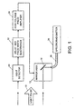
- FIG. 1 is a schematic diagram of the apparatus of the present invention.
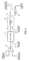
- FIG. 2 is a simplified schematic diagram of pulse timing circuitry used in the invention.
-
- As shown in the drawings for purposes of illustration, the present invention pertains to a technique for sampling a flash or pulse of radiation and inputting the sampled radiation to a spectroradiometer for analysis. For some applications, a light pulse from a solar simulator must be spectrally analyzed over a precisely defined time interval. Failure to select the time interval correctly may result in the analysis of a different spectral sample, which would lead to errors when the solar simulator is used to evaluate components such as solar cells and panels.
- In accordance with the present invention, light from a pulse of radiation is sampled using a high speed, electrically actuated shutter, which is switched to an open condition only during the desired time interval over which spectral analysis is to be performed. As shown in FIG. 1, a light pulse, indicated by
reference numeral 10, is received at the apparatus of the invention, from a radiation source such as a solar simulator (not shown). Thelight pulse 10 impinges on amirror assembly 12 configured as a high speed shutter, and on alight detector 14. When themirror assembly 12 is in an 'on' condition, light falling on amirror 16 that is part of theassembly 12 is reflected into a fiberoptic bundle 18, for transmission to aspectroradiometer 20. When the mirror assembly is an 'off' condition, light from thepulse 10 is not reflected into thefiber bundle 18, and thespectroradiometer 20 derives practically no input from thelight pulse 10. - The
light detector 14 generates an output signal when light from thepulse 10 exceeds a selected and very low threshold level. This output signal is coupled to delay andpulse width electronics 22 and initiates a timing sequence. Theelectronics 22 includes two manually controllable timers. A first timer in theelectronics 22 measures a delay time from near the beginning of the pulse to the beginning of a time interval over which spectral analysis will be performed. A second timer in theelectronics 22 measures the width of a timing pulse that is generated by the electronics to control the time for which themirror assembly 12 will remain in the open condition. The timing pulse generated in theelectronics 22 is coupled to a highvoltage pulse amplifier 24, which outputs control signals to themirror assembly 12. - The
mirror assembly 12 preferably includes a deformable membrane mirror (16) and the control signals received from the highvoltage pulse amplifier 24 "open" the shutter formed by the mirror assembly by removing power from the mirror. In the open condition, the mirror16 is substantially planar. Light from thepulse 10 is then reflected by themirror 16 into theoptical fiber bundle 18 and is input to thespectroradiometer 20. At the end of the desired sampling pulse, a high voltage control signal is supplied from the highvoltage pulse amplifier 24 to themirror assembly 12. The control signal is applied to thedeformable mirror 16, distorting the mirror surface sufficiently to prevent light from thepulse 10 from being launched into theoptical fiber bundle 18. - The
mirror assembly 12 may be, for example, a membrane mirror light system (MMLS) available from Optron System, Inc., of Bedford, Massachusetts. TheMMLS mirror 16 is deformed in the 'off' condition by applying a voltage to its multiple electrodes. When the applied voltage is sufficiently high, themirror 16 is deformed to include a two-dimensional array of dimples in its surface, which scatters the incident light to such a degree that practically no light is launched into theoptical fiber bundle 18. When the applied voltage is removed, during the desired sampling interval, themirror 16 reverts to its planar configuration and reflects light from thepulse 10 into theoptical fiber bundle 18. Other optical components, such as lenses (not shown) may be employed, as needed, to launch the reflected light into thefiber bundle 18. - The delay and
pulse width electronics 22 may take any of a number of specific forms. FIG. 2 depicts the broad functions of theelectronics 22. As indicated, an input signal from thelight detector 14 is coupled to acomparator 30, the other input of which is a threshold level, online 32, that can be changed by the user. Depending on the application of the invention, the threshold at which the circuitry is triggered to begin timing is user selectable by this input online 32. The output of thecomparator 30 is a trigger signal that is applied to adelay timer 34, which generates an output pulse online 36, the trailing edge of which is used to trigger asecond timer 38. Thedelay timer 34 is user controllable, as indicated by a control input online 40, to trigger thesecond timer 38 at a selected time delay following the triggering of thefirst timer 34. Thesecond timer 38 generates an output pulse online 42, the pulse being controllable in width by another user control input online 44. Thus, thefirst timer 34 determines the start time of the output pulse online 42 and thesecond timer 38 determines the width of the output pulse online 42. The output pulse online 42 is inverted, as indicated byinverter 46, and coupled to the high voltage pulse amplifier 24 (FIG. 1) to control themirror assembly 12. Inverted and noninverted forms of the output pulse online 42 may also be coupled to thespectroradiometer 20. - The
delay timer 34 andpulse width timer 38 may be implemented in a variety of conventional ways. For example, a commonly used integrated circuit known by the standard designation NE556 provides a dual timer well suited for this purpose. Control of the delay time and the pulse width can be effected by use of variable resistors or variable capacitors in a resistor-capacitor (R-C) timing circuit associated with each of the timers. Similarly, control of the threshold sensitivity determined in thecomparator 30 can be effected by a variable resistor or similar means. The highvoltage pulse amplifier 24 may be of any suitable design. If themirror assembly 12 is the MMLS manufactured by Optron System, Inc., a matching pulse amplifier designated PH-1 is available from the same manufacturer. - It will be appreciated from the foregoing that the present invention represents a significant advance in the field of spectroradiometry. In particular, the invention provides a more rapidly responsive shutter to allow spectral analysis of a pulse of radiation over a selected time interval shorter than the total duration of the pulse of radiation. It will also be appreciated that, although a specific embodiment of the invention has been illustrated and described by way of example, various modifications may be made without departing from the spirit and scope of the invention. Accordingly, the invention should not be limited except as by the appended claims.
Claims (10)
- A variable speed shutter for use in spectroradiometry, comprising:an optical detector for sensing initiation of a pulse of radiation;timing electronics for producing a control pulse or a desired duration less than the duration of the pulse of radiation, and starting at a desired delay time after sensing of initiation of the pulse of radiation; anda mirror assembly comprising a deformable mirror that is aligned to receive the pulse of radiation, and that is responsive to the control pulse to assume a fully reflective state for the duration of the control pulse, wherein the deformable mirror in the fully reflective state reflects the pulse of radiation to allow its further processing, and wherein the deformable mirror not in the fully reflective state prevents further processing of the pulse of radiation.
- A variable speed shutter as defined in claim 1, wherein the deformable mirror is an electrically actuated deformable membrane mirror.
- A variable speed shutter as defined in claim 1, wherein the timing electronics comprise:a first timer, triggered by a signal from the optical detector upon sensing initiation of the pulse of radiation, wherein the first timer generates an output signal when a selected delay time has elapsed after the initiation of the pulse of radiation; anda second timer, triggered by the output signal from the first timer, for generating the control pulse.
- A variable speed shutter as defined in claim 3, wherein:the first timer further comprises means for controlling the selected delay time; andthe second timer further comprises means for controlling the duration of the control pulse.
- A variable speed shutter as defined in claim 6, wherein the timing electronics further comprise:a comparator, for comparing the signal from the optical detector with a threshold level; andmeans for selecting the threshold level.
- A method for sampling a pulse of radiation, comprising the steps of:sensing the beginning of the pulse of radiation;in response to the sensing step, triggering operation of a first timer, to measure a desired delay before sampling the pulse of radiation;in response to operation of the first timer, triggering a second timer, to generate a sampling pulse starting at a time determined by the first timer and having a duration determined by the second timer;applying the sampling pulse to control a deformable mirror and thereby switching the deformable mirror to a fully reflective state for the duration of the sampling pulse; andreflecting the pulse of radiation into a radiation measurement instrument when the deformable mirror is in the fully reflective state, to perform spectral analysis of the pulse of radiation during the time of the selected sampling pulse.
- A method as defined in claim 6, wherein the sensing step comprises:generating an electrical signal from incident radiation received in the pulse of radiation;comparing the electrical signal with a threshold signal; andgenerating a triggering signal and applying it to the first timer when the electrical signal exceeds the threshold signal.
- A method as defined in claim 7, wherein the sensing step further comprises varying the threshold signal to obtain a desired level of sensitivity to the beginning of the pulse of radiation.
- A method as defined in claim 6, and further comprising:adjusting the first timer to obtain a desired starting time for the sampling pulse; andadjusting the second timer to obtain a desired duration of the sampling pulse.
- A method as defined in claim 6, and further comprising:applying the sampling pulse to the radiation measurement instrument.
Applications Claiming Priority (2)
| Application Number | Priority Date | Filing Date | Title |
|---|---|---|---|
| US10/876,207 US7078675B2 (en) | 2004-06-23 | 2004-06-23 | Variable high speed shutter for spectroradiometry |
| US876207 | 2004-06-23 |
Publications (2)
| Publication Number | Publication Date |
|---|---|
| EP1610107A1 true EP1610107A1 (en) | 2005-12-28 |
| EP1610107B1 EP1610107B1 (en) | 2007-01-03 |
Family
ID=34941384
Family Applications (1)
| Application Number | Title | Priority Date | Filing Date |
|---|---|---|---|
| EP05253101A Expired - Lifetime EP1610107B1 (en) | 2004-06-23 | 2005-05-19 | Variable high speed shutter for spectroradiometry |
Country Status (4)
| Country | Link |
|---|---|
| US (1) | US7078675B2 (en) |
| EP (1) | EP1610107B1 (en) |
| AT (1) | ATE350653T1 (en) |
| DE (1) | DE602005000407T2 (en) |
Cited By (1)
| Publication number | Priority date | Publication date | Assignee | Title |
|---|---|---|---|---|
| EP2390637A4 (en) * | 2009-01-22 | 2016-01-27 | Nat Inst Of Advanced Ind Scien | STANDARD SPECTRORADIOMETER |
Families Citing this family (3)
| Publication number | Priority date | Publication date | Assignee | Title |
|---|---|---|---|---|
| US7232111B2 (en) * | 2004-01-12 | 2007-06-19 | Masco Corporation Of Indiana | Control arrangement for an automatic residential faucet |
| NL2003254A (en) * | 2008-08-21 | 2010-03-10 | Asml Netherlands Bv | Inspection method and apparatus, lithographic apparatus, lithographic processing cell and device manufacturing method. |
| US9147565B1 (en) | 2014-12-30 | 2015-09-29 | Morpho Detection, Llc | Ion mobility spectrometer and method of using the same |
Citations (3)
| Publication number | Priority date | Publication date | Assignee | Title |
|---|---|---|---|---|
| US4647199A (en) * | 1984-09-14 | 1987-03-03 | The Perkin-Elmer Corporation | Automatic shutter system |
| US6178033B1 (en) * | 1999-03-28 | 2001-01-23 | Lucent Technologies | Micromechanical membrane tilt-mirror switch |
| EP1318426A1 (en) * | 2001-12-07 | 2003-06-11 | C.R.F. Società Consortile per Azioni | Micromirror with electrostatically controlled microshutter, array of micromirrors and infrared spectrophotometer comprising said array |
Family Cites Families (1)
| Publication number | Priority date | Publication date | Assignee | Title |
|---|---|---|---|---|
| DE3741856C1 (en) * | 1987-12-10 | 1989-04-20 | Messerschmitt Boelkow Blohm | Optronic protected missile detection |
-
2004
- 2004-06-23 US US10/876,207 patent/US7078675B2/en not_active Expired - Fee Related
-
2005
- 2005-05-19 AT AT05253101T patent/ATE350653T1/en not_active IP Right Cessation
- 2005-05-19 DE DE602005000407T patent/DE602005000407T2/en not_active Expired - Fee Related
- 2005-05-19 EP EP05253101A patent/EP1610107B1/en not_active Expired - Lifetime
Patent Citations (3)
| Publication number | Priority date | Publication date | Assignee | Title |
|---|---|---|---|---|
| US4647199A (en) * | 1984-09-14 | 1987-03-03 | The Perkin-Elmer Corporation | Automatic shutter system |
| US6178033B1 (en) * | 1999-03-28 | 2001-01-23 | Lucent Technologies | Micromechanical membrane tilt-mirror switch |
| EP1318426A1 (en) * | 2001-12-07 | 2003-06-11 | C.R.F. Società Consortile per Azioni | Micromirror with electrostatically controlled microshutter, array of micromirrors and infrared spectrophotometer comprising said array |
Cited By (1)
| Publication number | Priority date | Publication date | Assignee | Title |
|---|---|---|---|---|
| EP2390637A4 (en) * | 2009-01-22 | 2016-01-27 | Nat Inst Of Advanced Ind Scien | STANDARD SPECTRORADIOMETER |
Also Published As
| Publication number | Publication date |
|---|---|
| US20050285028A1 (en) | 2005-12-29 |
| DE602005000407T2 (en) | 2008-01-03 |
| EP1610107B1 (en) | 2007-01-03 |
| ATE350653T1 (en) | 2007-01-15 |
| DE602005000407D1 (en) | 2007-02-15 |
| US7078675B2 (en) | 2006-07-18 |
Similar Documents
| Publication | Publication Date | Title |
|---|---|---|
| EP0426117B1 (en) | A method for calibrating an optical attenuator | |
| CN103091289B (en) | Automatic experimental platform based on laser-induced breakdown spectroscopy analysis technology | |
| CN114567772B (en) | Measuring method and measuring system for optical gating time characteristics of image intensifier | |
| KR950021924A (en) | Laser rangefinder test system to perform distance simulation | |
| JP2000035376A (en) | Optical component tester | |
| US7129483B2 (en) | Laser desorption and ionization mass spectrometer with quantitative reproducibility | |
| US7078675B2 (en) | Variable high speed shutter for spectroradiometry | |
| CN104823071B (en) | For measurement distance value and the apparatus and method of range image | |
| US20100260229A1 (en) | Apparatus for Testing Infrared Sensors | |
| CN104048758B (en) | The method improving FT-NIR spectra certainty of measurement based on Electro-optical Modulation waveguide | |
| US6987561B2 (en) | System and apparatus for testing a micromachined optical device | |
| CN104048812B (en) | An experimental device for the effect of continuous wave high-energy laser irradiation on optical components | |
| DE10326085A1 (en) | Object distance-estimation apparatus determines distance of object, based on calculating time difference of reflected wave and delayed reference wave | |
| CN119070126A (en) | Laser energy adjustment method and target laser | |
| EP0943925A3 (en) | Electro-optic sampling oscilloscope | |
| KR102528823B1 (en) | Apparatus and method for measuring time-resolved thermal image | |
| DE102005063373A1 (en) | Solar illumination simulator used in measuring solar cell opto-electronic characteristics, comprises pulsed high intensity source with reflective dynamic spectral mask | |
| CN114697644A (en) | Debugging calibrating device | |
| CN109387903A (en) | Light path coupling system and optical measuring system | |
| JPS5922172B2 (en) | Fragmentation method | |
| RU2757471C1 (en) | Method for calibration/verification of the laser radiation power measuring instrument | |
| CN110095190A (en) | The pulsed optical signals method of sampling and light-pulse generator spectrometer | |
| US3229497A (en) | Shutter testing apparatus | |
| CN114200068B (en) | Diode array detector with reference end and control method | |
| JPH06308032A (en) | Fluorescence phosphorescence intensity meter |
Legal Events
| Date | Code | Title | Description |
|---|---|---|---|
| PUAI | Public reference made under article 153(3) epc to a published international application that has entered the european phase |
Free format text: ORIGINAL CODE: 0009012 |
|
| 17P | Request for examination filed |
Effective date: 20050610 |
|
| AK | Designated contracting states |
Kind code of ref document: A1 Designated state(s): AT BE BG CH CY CZ DE DK EE ES FI FR GB GR HU IE IS IT LI LT LU MC NL PL PT RO SE SI SK TR |
|
| AX | Request for extension of the european patent |
Extension state: AL BA HR LV MK YU |
|
| GRAP | Despatch of communication of intention to grant a patent |
Free format text: ORIGINAL CODE: EPIDOSNIGR1 |
|
| AKX | Designation fees paid |
Designated state(s): AT BE BG CH CY CZ DE DK EE ES FI FR GB GR HU IE IS IT LI LT LU MC NL PL PT RO SE SI SK TR |
|
| GRAS | Grant fee paid |
Free format text: ORIGINAL CODE: EPIDOSNIGR3 |
|
| GRAA | (expected) grant |
Free format text: ORIGINAL CODE: 0009210 |
|
| AK | Designated contracting states |
Kind code of ref document: B1 Designated state(s): AT BE BG CH CY CZ DE DK EE ES FI FR GB GR HU IE IS IT LI LT LU MC NL PL PT RO SE SI SK TR |
|
| PG25 | Lapsed in a contracting state [announced via postgrant information from national office to epo] |
Ref country code: NL Free format text: LAPSE BECAUSE OF FAILURE TO SUBMIT A TRANSLATION OF THE DESCRIPTION OR TO PAY THE FEE WITHIN THE PRESCRIBED TIME-LIMIT Effective date: 20070103 Ref country code: CH Free format text: LAPSE BECAUSE OF FAILURE TO SUBMIT A TRANSLATION OF THE DESCRIPTION OR TO PAY THE FEE WITHIN THE PRESCRIBED TIME-LIMIT Effective date: 20070103 Ref country code: LI Free format text: LAPSE BECAUSE OF FAILURE TO SUBMIT A TRANSLATION OF THE DESCRIPTION OR TO PAY THE FEE WITHIN THE PRESCRIBED TIME-LIMIT Effective date: 20070103 Ref country code: SI Free format text: LAPSE BECAUSE OF FAILURE TO SUBMIT A TRANSLATION OF THE DESCRIPTION OR TO PAY THE FEE WITHIN THE PRESCRIBED TIME-LIMIT Effective date: 20070103 Ref country code: PL Free format text: LAPSE BECAUSE OF FAILURE TO SUBMIT A TRANSLATION OF THE DESCRIPTION OR TO PAY THE FEE WITHIN THE PRESCRIBED TIME-LIMIT Effective date: 20070103 Ref country code: DK Free format text: LAPSE BECAUSE OF FAILURE TO SUBMIT A TRANSLATION OF THE DESCRIPTION OR TO PAY THE FEE WITHIN THE PRESCRIBED TIME-LIMIT Effective date: 20070103 Ref country code: FI Free format text: LAPSE BECAUSE OF FAILURE TO SUBMIT A TRANSLATION OF THE DESCRIPTION OR TO PAY THE FEE WITHIN THE PRESCRIBED TIME-LIMIT Effective date: 20070103 Ref country code: AT Free format text: LAPSE BECAUSE OF FAILURE TO SUBMIT A TRANSLATION OF THE DESCRIPTION OR TO PAY THE FEE WITHIN THE PRESCRIBED TIME-LIMIT Effective date: 20070103 |
|
| REG | Reference to a national code |
Ref country code: GB Ref legal event code: FG4D |
|
| REF | Corresponds to: |
Ref document number: 602005000407 Country of ref document: DE Date of ref document: 20070215 Kind code of ref document: P |
|
| REG | Reference to a national code |
Ref country code: IE Ref legal event code: FG4D |
|
| PG25 | Lapsed in a contracting state [announced via postgrant information from national office to epo] |
Ref country code: SE Free format text: LAPSE BECAUSE OF FAILURE TO SUBMIT A TRANSLATION OF THE DESCRIPTION OR TO PAY THE FEE WITHIN THE PRESCRIBED TIME-LIMIT Effective date: 20070403 Ref country code: BG Free format text: LAPSE BECAUSE OF FAILURE TO SUBMIT A TRANSLATION OF THE DESCRIPTION OR TO PAY THE FEE WITHIN THE PRESCRIBED TIME-LIMIT Effective date: 20070403 |
|
| PG25 | Lapsed in a contracting state [announced via postgrant information from national office to epo] |
Ref country code: ES Free format text: LAPSE BECAUSE OF FAILURE TO SUBMIT A TRANSLATION OF THE DESCRIPTION OR TO PAY THE FEE WITHIN THE PRESCRIBED TIME-LIMIT Effective date: 20070414 |
|
| PG25 | Lapsed in a contracting state [announced via postgrant information from national office to epo] |
Ref country code: IS Free format text: LAPSE BECAUSE OF FAILURE TO SUBMIT A TRANSLATION OF THE DESCRIPTION OR TO PAY THE FEE WITHIN THE PRESCRIBED TIME-LIMIT Effective date: 20070503 |
|
| PG25 | Lapsed in a contracting state [announced via postgrant information from national office to epo] |
Ref country code: PT Free format text: LAPSE BECAUSE OF FAILURE TO SUBMIT A TRANSLATION OF THE DESCRIPTION OR TO PAY THE FEE WITHIN THE PRESCRIBED TIME-LIMIT Effective date: 20070604 |
|
| NLV1 | Nl: lapsed or annulled due to failure to fulfill the requirements of art. 29p and 29m of the patents act | ||
| PGFP | Annual fee paid to national office [announced via postgrant information from national office to epo] |
Ref country code: DE Payment date: 20070702 Year of fee payment: 3 |
|
| REG | Reference to a national code |
Ref country code: CH Ref legal event code: PL |
|
| ET | Fr: translation filed | ||
| PLBE | No opposition filed within time limit |
Free format text: ORIGINAL CODE: 0009261 |
|
| STAA | Information on the status of an ep patent application or granted ep patent |
Free format text: STATUS: NO OPPOSITION FILED WITHIN TIME LIMIT |
|
| PG25 | Lapsed in a contracting state [announced via postgrant information from national office to epo] |
Ref country code: SK Free format text: LAPSE BECAUSE OF FAILURE TO SUBMIT A TRANSLATION OF THE DESCRIPTION OR TO PAY THE FEE WITHIN THE PRESCRIBED TIME-LIMIT Effective date: 20070103 |
|
| 26N | No opposition filed |
Effective date: 20071005 |
|
| PG25 | Lapsed in a contracting state [announced via postgrant information from national office to epo] |
Ref country code: CZ Free format text: LAPSE BECAUSE OF FAILURE TO SUBMIT A TRANSLATION OF THE DESCRIPTION OR TO PAY THE FEE WITHIN THE PRESCRIBED TIME-LIMIT Effective date: 20070103 Ref country code: BE Free format text: LAPSE BECAUSE OF FAILURE TO SUBMIT A TRANSLATION OF THE DESCRIPTION OR TO PAY THE FEE WITHIN THE PRESCRIBED TIME-LIMIT Effective date: 20070103 Ref country code: RO Free format text: LAPSE BECAUSE OF FAILURE TO SUBMIT A TRANSLATION OF THE DESCRIPTION OR TO PAY THE FEE WITHIN THE PRESCRIBED TIME-LIMIT Effective date: 20070103 |
|
| PG25 | Lapsed in a contracting state [announced via postgrant information from national office to epo] |
Ref country code: MC Free format text: LAPSE BECAUSE OF NON-PAYMENT OF DUE FEES Effective date: 20070531 |
|
| PG25 | Lapsed in a contracting state [announced via postgrant information from national office to epo] |
Ref country code: LT Free format text: LAPSE BECAUSE OF FAILURE TO SUBMIT A TRANSLATION OF THE DESCRIPTION OR TO PAY THE FEE WITHIN THE PRESCRIBED TIME-LIMIT Effective date: 20070103 |
|
| PG25 | Lapsed in a contracting state [announced via postgrant information from national office to epo] |
Ref country code: GR Free format text: LAPSE BECAUSE OF FAILURE TO SUBMIT A TRANSLATION OF THE DESCRIPTION OR TO PAY THE FEE WITHIN THE PRESCRIBED TIME-LIMIT Effective date: 20070404 Ref country code: IT Free format text: LAPSE BECAUSE OF FAILURE TO SUBMIT A TRANSLATION OF THE DESCRIPTION OR TO PAY THE FEE WITHIN THE PRESCRIBED TIME-LIMIT Effective date: 20070103 |
|
| PGFP | Annual fee paid to national office [announced via postgrant information from national office to epo] |
Ref country code: FR Payment date: 20070517 Year of fee payment: 3 |
|
| PG25 | Lapsed in a contracting state [announced via postgrant information from national office to epo] |
Ref country code: IE Free format text: LAPSE BECAUSE OF NON-PAYMENT OF DUE FEES Effective date: 20070521 |
|
| PG25 | Lapsed in a contracting state [announced via postgrant information from national office to epo] |
Ref country code: EE Free format text: LAPSE BECAUSE OF FAILURE TO SUBMIT A TRANSLATION OF THE DESCRIPTION OR TO PAY THE FEE WITHIN THE PRESCRIBED TIME-LIMIT Effective date: 20070103 |
|
| REG | Reference to a national code |
Ref country code: FR Ref legal event code: ST Effective date: 20090119 |
|
| PG25 | Lapsed in a contracting state [announced via postgrant information from national office to epo] |
Ref country code: DE Free format text: LAPSE BECAUSE OF NON-PAYMENT OF DUE FEES Effective date: 20081202 Ref country code: FR Free format text: LAPSE BECAUSE OF NON-PAYMENT OF DUE FEES Effective date: 20080602 |
|
| PG25 | Lapsed in a contracting state [announced via postgrant information from national office to epo] |
Ref country code: CY Free format text: LAPSE BECAUSE OF FAILURE TO SUBMIT A TRANSLATION OF THE DESCRIPTION OR TO PAY THE FEE WITHIN THE PRESCRIBED TIME-LIMIT Effective date: 20070103 |
|
| PG25 | Lapsed in a contracting state [announced via postgrant information from national office to epo] |
Ref country code: LU Free format text: LAPSE BECAUSE OF NON-PAYMENT OF DUE FEES Effective date: 20070519 |
|
| PG25 | Lapsed in a contracting state [announced via postgrant information from national office to epo] |
Ref country code: HU Free format text: LAPSE BECAUSE OF FAILURE TO SUBMIT A TRANSLATION OF THE DESCRIPTION OR TO PAY THE FEE WITHIN THE PRESCRIBED TIME-LIMIT Effective date: 20070704 Ref country code: TR Free format text: LAPSE BECAUSE OF FAILURE TO SUBMIT A TRANSLATION OF THE DESCRIPTION OR TO PAY THE FEE WITHIN THE PRESCRIBED TIME-LIMIT Effective date: 20070103 |
|
| GBPC | Gb: european patent ceased through non-payment of renewal fee |
Effective date: 20090519 |
|
| PG25 | Lapsed in a contracting state [announced via postgrant information from national office to epo] |
Ref country code: GB Free format text: LAPSE BECAUSE OF NON-PAYMENT OF DUE FEES Effective date: 20090519 |