EP1610102A1 - Vorrichtung zum Erfassen des Füllstandes in einem Behälter - Google Patents
Vorrichtung zum Erfassen des Füllstandes in einem Behälter Download PDFInfo
- Publication number
- EP1610102A1 EP1610102A1 EP05105531A EP05105531A EP1610102A1 EP 1610102 A1 EP1610102 A1 EP 1610102A1 EP 05105531 A EP05105531 A EP 05105531A EP 05105531 A EP05105531 A EP 05105531A EP 1610102 A1 EP1610102 A1 EP 1610102A1
- Authority
- EP
- European Patent Office
- Prior art keywords
- container
- electrodes
- receiving device
- cavity
- formation
- Prior art date
- Legal status (The legal status is an assumption and is not a legal conclusion. Google has not performed a legal analysis and makes no representation as to the accuracy of the status listed.)
- Granted
Links
Images
Classifications
-
- G—PHYSICS
- G01—MEASURING; TESTING
- G01F—MEASURING VOLUME, VOLUME FLOW, MASS FLOW OR LIQUID LEVEL; METERING BY VOLUME
- G01F23/00—Indicating or measuring liquid level or level of fluent solid material, e.g. indicating in terms of volume or indicating by means of an alarm
- G01F23/22—Indicating or measuring liquid level or level of fluent solid material, e.g. indicating in terms of volume or indicating by means of an alarm by measuring physical variables, other than linear dimensions, pressure or weight, dependent on the level to be measured, e.g. by difference of heat transfer of steam or water
- G01F23/26—Indicating or measuring liquid level or level of fluent solid material, e.g. indicating in terms of volume or indicating by means of an alarm by measuring physical variables, other than linear dimensions, pressure or weight, dependent on the level to be measured, e.g. by difference of heat transfer of steam or water by measuring variations of capacity or inductance of capacitors or inductors arising from the presence of liquid or fluent solid material in the electric or electromagnetic fields
- G01F23/263—Indicating or measuring liquid level or level of fluent solid material, e.g. indicating in terms of volume or indicating by means of an alarm by measuring physical variables, other than linear dimensions, pressure or weight, dependent on the level to be measured, e.g. by difference of heat transfer of steam or water by measuring variations of capacity or inductance of capacitors or inductors arising from the presence of liquid or fluent solid material in the electric or electromagnetic fields by measuring variations in capacitance of capacitors
- G01F23/265—Indicating or measuring liquid level or level of fluent solid material, e.g. indicating in terms of volume or indicating by means of an alarm by measuring physical variables, other than linear dimensions, pressure or weight, dependent on the level to be measured, e.g. by difference of heat transfer of steam or water by measuring variations of capacity or inductance of capacitors or inductors arising from the presence of liquid or fluent solid material in the electric or electromagnetic fields by measuring variations in capacitance of capacitors for discrete levels
-
- D—TEXTILES; PAPER
- D06—TREATMENT OF TEXTILES OR THE LIKE; LAUNDERING; FLEXIBLE MATERIALS NOT OTHERWISE PROVIDED FOR
- D06F—LAUNDERING, DRYING, IRONING, PRESSING OR FOLDING TEXTILE ARTICLES
- D06F39/00—Details of washing machines not specific to a single type of machines covered by groups D06F9/00 - D06F27/00
- D06F39/08—Liquid supply or discharge arrangements
- D06F39/087—Water level measuring or regulating devices
-
- A—HUMAN NECESSITIES
- A47—FURNITURE; DOMESTIC ARTICLES OR APPLIANCES; COFFEE MILLS; SPICE MILLS; SUCTION CLEANERS IN GENERAL
- A47L—DOMESTIC WASHING OR CLEANING; SUCTION CLEANERS IN GENERAL
- A47L15/00—Washing or rinsing machines for crockery or tableware
- A47L15/42—Details
- A47L15/4244—Water-level measuring or regulating arrangements
-
- A—HUMAN NECESSITIES
- A47—FURNITURE; DOMESTIC ARTICLES OR APPLIANCES; COFFEE MILLS; SPICE MILLS; SUCTION CLEANERS IN GENERAL
- A47L—DOMESTIC WASHING OR CLEANING; SUCTION CLEANERS IN GENERAL
- A47L15/00—Washing or rinsing machines for crockery or tableware
- A47L15/42—Details
- A47L15/44—Devices for adding cleaning agents; Devices for dispensing cleaning agents, rinsing aids or deodorants
- A47L15/4418—Devices for adding cleaning agents; Devices for dispensing cleaning agents, rinsing aids or deodorants in the form of liquids
-
- D—TEXTILES; PAPER
- D06—TREATMENT OF TEXTILES OR THE LIKE; LAUNDERING; FLEXIBLE MATERIALS NOT OTHERWISE PROVIDED FOR
- D06F—LAUNDERING, DRYING, IRONING, PRESSING OR FOLDING TEXTILE ARTICLES
- D06F39/00—Details of washing machines not specific to a single type of machines covered by groups D06F9/00 - D06F27/00
- D06F39/02—Devices for adding soap or other washing agents
- D06F39/022—Devices for adding soap or other washing agents in a liquid state
Definitions
- the invention relates to a device for detecting the filling state in a Container, preferably in a container, for storing liquids in a household appliance, with a cavity enclosing Body with walls of dielectric material, in particular plastic, under Use of electrodes formed of electrically conductive material as elements an electrical capacitor, which in the operating position of the container with an evaluation circuit is coupled.
- Such a device is known from DE 32 36 291 C2.
- On or two electrodes are arranged next to one another in a wall of the liquid container, between which a liquid facing surface of a Electrode to the corresponding surface of the other electrode an electric field forms arcuate.
- the field will be strongest where the electrode surfaces are lie closest. These are the ones facing each other narrow edges of the adjacent electrodes. Between these narrow edges, therefore, forms the field with the greatest density, and between These edges are defined by the unchangeable dielectric Condition, namely air, when the electrodes lie flat on the outer wall, or the plastic of the wall, in which the electrodes are possibly embedded. Therefore Dielectric changes in the container, such as sinking liquid level at the level of the attached electrodes, only on the very weak pronounced field effect, which is arcuate from the one, the liquid facing surface of the one electrode to the corresponding surface of the other electrode extends. The influence of the sinking is correspondingly low Liquid level can be on this weak field, so the sensitivity of the entire measuring system with respect to dielectric changes in the container will leave wishes.
- dielectric changes in the air such as changes the absolute humidity of the air
- changes the absolute humidity of the air on the highly concentrated field between The electrode edges of exposed electrodes have a relatively high influence so that these unwanted effects are the true rating of Measurement results of the capacitance of the capacitor formed from the electrodes in terms of dielectric changes of the container contents very difficult. A sufficiently accurate detection of the filling state in this container is therefore not possible.
- the invention is based on the object, a device of the aforementioned Specify the type, in terms of measurement reliability for detecting the filling state in a container is considerably more accurate than in the prior art. Above all, it does not matter so much, the filling in proportions The maximum possible degree of filling to capture, but above all a reliable To be able to make a statement about whether the container, for example, almost empty or almost full.
- this object is achieved according to the characterizing part of the claim 1 achieved in that the cavity forming body of the container a Has molding, the at least two opposing boundary walls has that closely with the at least approximately parallel to each other standing electrodes correspond and their distance from each other enough is small in order to measure at usual in electronic circuits small measuring voltages (e.g. 5V) between the electrodes an approximately interference-free electric field allow.
- small measuring voltages e.g. 5V
- the container having a shallow cavity forms for the liquid manages the liquid within the room to be arranged, bounded by the two opposing electrodes is without the electrodes themselves having contact with the liquid. Thereby the liquid to be monitored is located directly in the room containing the strongest achievable field concentration has. Any dielectric change in this Space immediately becomes a measurable change in the capacity of the cause the capacitor formed by the electrodes.
- the container is insertable into a receiving device and the molding is attached to the first dipping into the receiving device side, arise particularly useful conditions for connecting the electrodes with the evaluation and easier attachment and positioning of the Electrodes to the liquid to be monitored in the most suitable To bring space between the electrodes.
- the further develop device according to the invention in that the receiving device for introducing the container along an at least approximately horizontal Track is formed.
- the receiving device can for inserting the container instead of the horizontal arrangement along a be formed at least approximately vertical route. Then already lead smaller quantity differences of the liquid to be monitored to a measurable Change in capacity. This would be a continuous recording of the Fill state possible.
- the molding near the bottom of the cavity is arranged, can be seen in the simplest way, when the stockpiled Liquid is running low, or if there is already a sufficient amount of liquid in the container when it is intended to catch a liquid is.
- the formation can also be near the top of the cavity be arranged when the approximate maximum degree of filling - in the positive as in the negative sense - a container should be monitored.
- Electrodes in the receiving device arranged so that the formation between the two arranged in the receiving device electrodes, when the container has been inserted to the final position in the receiving device is. Then no electrical parts on the moving container attached when handling the container outside the receiving device may be subjected to an improper treatment.
- the electrodes according to another advantageous embodiment of the invention directly connected to the two mutually opposite boundary walls are. Then, the electrodes also advantageously have contact elements on, in the operating position of the container with mating contacts of the receiving device are connected.
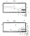
- the receiving device in Fig. 1 and Fig. 2 is in each case by a closed Housing 1 or 21 with an opening 2 or 22 through which the container 3 and 23, respectively can be inserted in a horizontal direction.
- the containers 3 and 23 have on their first entering during the insertion into the housing 1 or 21 page 4 or 24 a molding 5 and 25, respectively, positioned in the rear floor area 6 and 26 respectively is.
- the container 3 or 23 also has one or more not shown openings for filling and / or emptying its cavity 7 or 27.
- the housing 1 shown in FIG. 1 has on its rear side 8 an extension 9, in a distance space 10 between the general part of the container. 3 and the molding 5 protrudes.
- an electrode 11 is attached, that of a second electrode 12 as accurately as possible and parallel to each other stands.
- This second electrode 12 is attached to the inside of the case bottom. Both electrodes 11 and 12 are firmly fixed in the housing 1 lines 13 electrically connected to an evaluation circuit 14.
- the container 3 is over half filled with a liquid 15 which is at the bottom also flows into the molding 5. This changes the electric field between The electrodes 11 and 12 dramatically, because the liquid one of the before in the formation 5 existing air significantly different dielectric constant having.
- the evaluation circuit 14 recognizes and therefore signals that the container 3 is sufficiently full.
- FIG. 1 has the advantage that the container itself no electrical conductive parts are present.
- a container is therefore ideal for the storage of chemically reacting liquids, such as detergents for washing machines or dishwashers, or for collecting condensate at household laundry dryers.
- Such condensates contain regularly still low residual detergent and must therefore ebenfallls in the long run be calculated to the reactive substances.
- the container 23 shown in Fig. 2 is also similar in a housing 21 that of FIG. 1.
- the container 23 has a similar shape 25 like the container 3 in Fig. 1, its housing 21 on the back 24 has no Extension, because no electrodes are attached to the housing 21. Rather, they are the required for the invention electrodes 16 and 17 directly on or in the wall of the opposing boundary walls 18 and 19th the molding 25 is arranged.
- the electrodes 16 and 17 can do so from the outside glued or welded on the boundary walls 18 and 19 or in the material of the boundary walls be embedded.
- the electrodes 16 and 17 have at their the housing rear wall 28 facing Ends each have a pin 29 and 30, the operating position of the container 23rd through an associated aperture in the housing rear wall 28 therethrough protrudes.
- a respective female connector 31 and 32nd attached, which via electrical lines 33 with an evaluation circuit 34th are connected.
- the containers can also be permanently installed containers or containers in any other direction movable, for example, vertically movable, inserted into a receiving device are.
- the receiving device must also not enclosing the container Be housing.
- the formations 5 and 25 of the container 3 and 23 can both - As shown here - in the bottom portion 6 and 26 of the container or on be arranged completely different locations of the container - depending on which particular Fill state to be detected.
- the electrodes - no matter how and where they are placed in or on the container - should have a distance A to each other, which has been chosen so large that at a small measuring voltage of usually 5 V forms an electric field, at a desirably small amount of liquid within the Room of the formation 5 or 25 still a measurable difference to the field in the total filling of this room results.
- This measurable difference needs of course also have a sufficiently large distance to the otherwise still influencing disturbance fields, which from the environment of the measuring location on the Electrode field of the detection device according to the invention act regularly can.
- other disturbances can be the electronic evaluation complicate such as soiling, tolerances or material changes. Therefore the electrode distance must be chosen sufficiently large, if he too should be kept smaller for the electronic evaluation.
- a further embodiment of the invention can be at a horizontal or vertical oriented container also several pairs of electrodes at different heights be arranged according to the specification by claim 1. Then the Fill level be monitored gradually.
- the electrodes can also change the capacitance upon contact or interrupting the contact for the electrodes to detect the presence the container can be used in the receiving device.
Landscapes
- Engineering & Computer Science (AREA)
- Physics & Mathematics (AREA)
- Power Engineering (AREA)
- Electromagnetism (AREA)
- Thermal Sciences (AREA)
- Fluid Mechanics (AREA)
- General Physics & Mathematics (AREA)
- Textile Engineering (AREA)
- Measurement Of Levels Of Liquids Or Fluent Solid Materials (AREA)
- Investigating Or Analyzing Materials By The Use Of Electric Means (AREA)
Abstract
Description
- Fig. 1
- einen in eine Aufnahmeeinrichtung eingesetzten Behälter gemäß der Erfindung mit Elektroden, die in der Aufnahmeeinrichtung befestigt sind, und
- Fig. 2
- einen in eine Aufnahmeeinrichtung eingesetzten Behälter gemäß der Erfindung mit eigenen Elektroden.
Claims (8)
- Vorrichtung zum Erfassen des Füllzustandes in einem Behälter (3, 23), vorzugsweise in einem Behälter, der zum Aufbewahren von Flüssigkeiten (15, 35) in einem Haushaltgerät dient, mit einem einen Hohlraum (7, 27) umschließenden Körper mit Wänden aus dielektrischen Werkstoff, insbesondere Kunststoff, unter Verwendung von aus elektrisch leitendem Material gebildeten Elektroden (11, 12 bzw. 16, 17) als Elemente eines elektrischen Kondensators, der in Betriebsposition des Behälters (3, 23) mit einer Auswerteschaltung (14, 34) gekoppelt ist, dadurch gekennzeichnet, dass der den Hohlraum (7, 27) bildende Körper des Behälters (3, 23) eine Ausformung (5, 25) aufweist, die mindestens zwei einander gegenüber liegende Begrenzungswände (18, 19) hat, die eng mit den wenigstens annähernd parallel zueinander stehenden Elektroden (11, 12 bzw. 16, 17) korrespondieren und deren Abstand (A) voneinander genügend klein ist, um bei bei Elektronikschaltungen üblichen kleinen Messspannungen (z.B. 5V) zwischen den Elektroden (11, 12 bzw. 16, 17) ein annähernd störfreies elektrisches Feld entstehen zu lassen.
- Vorrichtung nach Anspruch 1, dadurch gekennzeichnet, dass der Behälter (3, 23) in eine Aufnahmeeinrichtung (1, 21) einführbar ist und die Ausformung (5, 25) an der zuerst in die Aufnahmeeinrichtung eintauchenden Seite (4, 24) angebracht ist.
- Vorrichtung nach Anspruch 2, dadurch gekennzeichnet, dass die Aufnahmeeinrichtung (1, 21) so ausgebildet ist, dass der Behälter (3, 23) entlang einer wenigstens annähernd horizontalen Strecke einführbar ist.
- Vorrichtung nach Anspruch 1, 2 oder 3, dadurch gekennzeichnet, dass die Ausformung (5, 25) in der Nähe des Bodenbereiches (6, 26) des Hohlraums (7, 27) angeordnet ist.
- Vorrichtung nach einem der vorstehenden Ansprüche, dadurch gekennzeichnet, dass die Ausformung in der Nähe des oberen Bereiches des Hohlraums (7, 27) angeordnet ist.
- Vorrichtung nach einem der Ansprüche 2 bis 5, dadurch gekennzeichnet, dass die Elektroden (11, 12) in der Aufnahmeeinrichtung (1) so angeordnet sind, dass die Ausformung (5) zwischen die beiden in der Aufnahmeeinrichtung (1) angeordneten Elektroden (11, 12) gelangt, wenn der Behälter (3) bis zur Endposition in die Aufnahmeeinrichtung (1) eingeführt worden ist.
- Vorrichtung nach einem der vorstehenden Ansprüche, dadurch gekennzeichnet, dass die Elektroden (16, 17) unmittelbar mit den beiden einander gegenüber liegenden Begrenzungswänden (18, 19) verbunden sind.
- Vorrichtung nach Anspruch 7, dadurch gekennzeichnet, dass die Elektroden (16, 17) Kontaktelemente (29, 30) aufweisen, die in Betriebsposition des Behälters (23) mit Gegenkontakten (31, 32) der Aufnahmeeinrichtung (21) verbunden sind.
Priority Applications (1)
| Application Number | Priority Date | Filing Date | Title |
|---|---|---|---|
| PL05105531T PL1610102T3 (pl) | 2004-06-22 | 2005-06-22 | Układ ze zbiornikiem cieczy do urządzenia gospodarstwa domowego i urządzenie gospodarstwa domowego |
Applications Claiming Priority (2)
| Application Number | Priority Date | Filing Date | Title |
|---|---|---|---|
| DE102004030049 | 2004-06-22 | ||
| DE102004030049A DE102004030049A1 (de) | 2004-06-22 | 2004-06-22 | Vorrichtung zum Erfassen des Füllstandes in einem Behälter |
Publications (2)
| Publication Number | Publication Date |
|---|---|
| EP1610102A1 true EP1610102A1 (de) | 2005-12-28 |
| EP1610102B1 EP1610102B1 (de) | 2018-03-07 |
Family
ID=35094471
Family Applications (1)
| Application Number | Title | Priority Date | Filing Date |
|---|---|---|---|
| EP05105531.7A Expired - Lifetime EP1610102B1 (de) | 2004-06-22 | 2005-06-22 | Anordnung mit Flüssigkeitsbehälter für ein Haushaltsgerät und Haushaltsgerät |
Country Status (4)
| Country | Link |
|---|---|
| EP (1) | EP1610102B1 (de) |
| DE (1) | DE102004030049A1 (de) |
| ES (1) | ES2665685T3 (de) |
| PL (1) | PL1610102T3 (de) |
Cited By (4)
| Publication number | Priority date | Publication date | Assignee | Title |
|---|---|---|---|---|
| FR2940037A1 (fr) * | 2008-12-22 | 2010-06-25 | Fagorbrandt Sas | Machine a laver la vaisselle comprenant un distributeur de detergent. |
| DE102010038668A1 (de) | 2010-07-29 | 2012-02-02 | BSH Bosch und Siemens Hausgeräte GmbH | Hausgerät mit Füllstandssensor und Verfahren zum Bestimmen eines Zustandsparameters in einem Hausgerät |
| EP3816591A1 (de) * | 2019-10-28 | 2021-05-05 | Robert Bosch GmbH | Behältervorrichtung, fahrzeug |
| EP3786341B1 (de) | 2019-08-29 | 2022-11-09 | LG Electronics Inc. | Waschmittelvorratsbehälter und verfahren zur herstellung desselben |
Families Citing this family (2)
| Publication number | Priority date | Publication date | Assignee | Title |
|---|---|---|---|---|
| DE102013102884A1 (de) * | 2013-03-21 | 2014-09-25 | Miele & Cie. Kg | Vorrichtung zur Dosierung einer flüssigen Prozesschemikalie |
| DE102015214214A1 (de) * | 2015-07-28 | 2017-02-02 | BSH Hausgeräte GmbH | Befeuchtungsvorrichtung für ein Haushaltskältegerät mit einem Tank und einer tankextern angeordneten Elektrode einer Füllstandssensorik sowie Haushaltskältegerät |
Citations (3)
| Publication number | Priority date | Publication date | Assignee | Title |
|---|---|---|---|---|
| DE3236291A1 (de) * | 1982-09-30 | 1984-04-05 | Bosch-Siemens Hausgeräte GmbH, 7000 Stuttgart | Vorrichtung zum erfassen und auswerten des fuellzustandes in behaeltern |
| GB2248939A (en) * | 1990-09-13 | 1992-04-22 | Pump International Limited | Capacitive switch for an automatic pump |
| DE19919597C1 (de) * | 1999-04-29 | 2000-06-29 | Siemens Ag | Überwachungseinrichtung für den Pegel einer Flüssigkeit |
Family Cites Families (4)
| Publication number | Priority date | Publication date | Assignee | Title |
|---|---|---|---|---|
| DE2924556A1 (de) * | 1979-06-19 | 1981-01-22 | Eaton Gmbh | Fuellstandsanzeigeeinrichtung |
| DE2944512A1 (de) * | 1979-11-03 | 1981-05-14 | Pelikan Ag, 3000 Hannover | Tintenbehaelter mit kapazitiver fuellstandsanzeige |
| JP3747683B2 (ja) * | 1999-04-07 | 2006-02-22 | 富士ゼロックス株式会社 | 粉体収容装置 |
| DE10309769B4 (de) * | 2002-03-08 | 2017-10-05 | Ust Umweltsensortechnik Gmbh | Anordnung zur Bestimmung von Zustandsgrößen für Flüssigkeiten in einem geschlossenen nichtmetallischen Behälter |
-
2004
- 2004-06-22 DE DE102004030049A patent/DE102004030049A1/de not_active Withdrawn
-
2005
- 2005-06-22 PL PL05105531T patent/PL1610102T3/pl unknown
- 2005-06-22 EP EP05105531.7A patent/EP1610102B1/de not_active Expired - Lifetime
- 2005-06-22 ES ES05105531.7T patent/ES2665685T3/es not_active Expired - Lifetime
Patent Citations (3)
| Publication number | Priority date | Publication date | Assignee | Title |
|---|---|---|---|---|
| DE3236291A1 (de) * | 1982-09-30 | 1984-04-05 | Bosch-Siemens Hausgeräte GmbH, 7000 Stuttgart | Vorrichtung zum erfassen und auswerten des fuellzustandes in behaeltern |
| GB2248939A (en) * | 1990-09-13 | 1992-04-22 | Pump International Limited | Capacitive switch for an automatic pump |
| DE19919597C1 (de) * | 1999-04-29 | 2000-06-29 | Siemens Ag | Überwachungseinrichtung für den Pegel einer Flüssigkeit |
Cited By (7)
| Publication number | Priority date | Publication date | Assignee | Title |
|---|---|---|---|---|
| FR2940037A1 (fr) * | 2008-12-22 | 2010-06-25 | Fagorbrandt Sas | Machine a laver la vaisselle comprenant un distributeur de detergent. |
| DE102010038668A1 (de) | 2010-07-29 | 2012-02-02 | BSH Bosch und Siemens Hausgeräte GmbH | Hausgerät mit Füllstandssensor und Verfahren zum Bestimmen eines Zustandsparameters in einem Hausgerät |
| EP2418315A2 (de) | 2010-07-29 | 2012-02-15 | BSH Bosch und Siemens Hausgeräte GmbH | Hausgerät mit Füllstandssensor und Verfahren zum Bestimmen eines Zustandsparameters in einem Hausgerät |
| EP3786341B1 (de) | 2019-08-29 | 2022-11-09 | LG Electronics Inc. | Waschmittelvorratsbehälter und verfahren zur herstellung desselben |
| EP4112800B1 (de) | 2019-08-29 | 2024-06-12 | LG Electronics Inc. | Waschmittelvorratsbehälter und verfahren zur herstellung desselben |
| EP4119717B1 (de) | 2019-08-29 | 2025-03-05 | LG Electronics Inc. | Reinigungsmittelzufuhrvorrichtung für ein wäschebehandlungsgerät |
| EP3816591A1 (de) * | 2019-10-28 | 2021-05-05 | Robert Bosch GmbH | Behältervorrichtung, fahrzeug |
Also Published As
| Publication number | Publication date |
|---|---|
| PL1610102T3 (pl) | 2018-08-31 |
| ES2665685T3 (es) | 2018-04-26 |
| EP1610102B1 (de) | 2018-03-07 |
| DE102004030049A1 (de) | 2006-01-12 |
Similar Documents
| Publication | Publication Date | Title |
|---|---|---|
| EP2400275B1 (de) | Berührungslose füllstandsmessung von flüssigkeiten | |
| EP1701646B1 (de) | Geschirrspülmaschine mit einem system zur füllstandserkennung | |
| EP3821211B1 (de) | Vorrichtungen und verfahren zur kapazitiven schaumdetektion in flüssigkeitsbehältern | |
| DE3331305A1 (de) | Dielektrisches feuchtemessgeraet | |
| EP2489996A1 (de) | Haushaltgerät mit Wasserstandssensor | |
| DE69525570T2 (de) | Probensammler für flüssige Proben | |
| DE2949497A1 (de) | Fluessigkeitsstandsmesser fuer einen kraftstofftank | |
| DE69206309T2 (de) | Flüssigkeitsniveaudetektor. | |
| EP1610102B1 (de) | Anordnung mit Flüssigkeitsbehälter für ein Haushaltsgerät und Haushaltsgerät | |
| DE102011079346A1 (de) | Konduktiver Leitfähigkeitssensor | |
| DE102005060363A1 (de) | Vorrichtung zur Ermittlung eines Füllstandes eines Flüssigkeitsbehälters eines Gerätes, insbesondere Hausgerätes sowie Füllstandssensor und Detektorschaltung hierfür | |
| DE112013005452T5 (de) | Durchgangsinspektionssvorrichtung | |
| DE8214409U1 (de) | Elektrisch gesteuertes geraet, insbesondere waschmaschine oder geschirrspueler, mit einer warnvorrichtung fuer wasserueberschwemmung oder -ausfluss | |
| DE19701225A1 (de) | Elektrischer Kondensations-Wäschetrockner mit Mikroprozessorsteuerung | |
| DE102011001354B4 (de) | Windschutz für eine Präzisionswaage | |
| EP1881307A2 (de) | Füllstandssensor für Fluide und/oder Schüttgüter | |
| DE102008031774B4 (de) | Sensoreinrichtung zur Bestimmung der Menge und/oder des Feuchtegrads von Wäsche in einem Wäschetrockner | |
| DE102004056981A1 (de) | Flüssigkeitssensor sowie Verfahren zum Messen der Füllstandshöhe | |
| DE3236291A1 (de) | Vorrichtung zum erfassen und auswerten des fuellzustandes in behaeltern | |
| DE102023106812A1 (de) | Haushaltsgerät | |
| DE10015764A1 (de) | Vorrichtung zum Messen des Volumens einer elektrisch leitenden Flüssigkeit | |
| EP2729252B1 (de) | Küvettenmodul mit elektrisch leitfähigem küvettenträger | |
| EP1677085A2 (de) | Kapazitiver Niveau-Sensor | |
| DE102004019351A1 (de) | Geschirrspülmaschine mit einem System zur Füllstandserkennung | |
| EP1699343B1 (de) | GESCHIRRSPüLMASCHINE MIT EINEM SYSTEM ZUR FüLLSTANDERKENNUNG |
Legal Events
| Date | Code | Title | Description |
|---|---|---|---|
| PUAI | Public reference made under article 153(3) epc to a published international application that has entered the european phase |
Free format text: ORIGINAL CODE: 0009012 |
|
| AK | Designated contracting states |
Kind code of ref document: A1 Designated state(s): AT BE BG CH CY CZ DE DK EE ES FI FR GB GR HU IE IS IT LI LT LU MC NL PL PT RO SE SI SK TR |
|
| AX | Request for extension of the european patent |
Extension state: AL BA HR LV MK YU |
|
| 17P | Request for examination filed |
Effective date: 20060628 |
|
| AKX | Designation fees paid |
Designated state(s): AT BE BG CH CY CZ DE DK EE ES FI FR GB GR HU IE IS IT LI LT LU MC NL PL PT RO SE SI SK TR |
|
| 17Q | First examination report despatched |
Effective date: 20140522 |
|
| RAP1 | Party data changed (applicant data changed or rights of an application transferred) |
Owner name: BSH HAUSGERAETE GMBH |
|
| GRAP | Despatch of communication of intention to grant a patent |
Free format text: ORIGINAL CODE: EPIDOSNIGR1 |
|
| RIC1 | Information provided on ipc code assigned before grant |
Ipc: G01F 23/26 20060101AFI20170922BHEP Ipc: D06F 39/02 20060101ALN20170922BHEP Ipc: D06F 58/04 20060101ALN20170922BHEP Ipc: A47L 15/00 20060101ALN20170922BHEP |
|
| INTG | Intention to grant announced |
Effective date: 20171011 |
|
| GRAS | Grant fee paid |
Free format text: ORIGINAL CODE: EPIDOSNIGR3 |
|
| GRAA | (expected) grant |
Free format text: ORIGINAL CODE: 0009210 |
|
| REG | Reference to a national code |
Ref country code: DE Ref legal event code: R081 Ref document number: 502005015793 Country of ref document: DE Owner name: BSH HAUSGERAETE GMBH, DE Free format text: FORMER OWNER: BSH BOSCH UND SIEMENS HAUSGERAETE GMBH, 81739 MUENCHEN, DE |
|
| AK | Designated contracting states |
Kind code of ref document: B1 Designated state(s): AT BE BG CH CY CZ DE DK EE ES FI FR GB GR HU IE IS IT LI LT LU MC NL PL PT RO SE SI SK TR |
|
| REG | Reference to a national code |
Ref country code: GB Ref legal event code: FG4D Free format text: NOT ENGLISH |
|
| REG | Reference to a national code |
Ref country code: CH Ref legal event code: EP Ref country code: AT Ref legal event code: REF Ref document number: 977072 Country of ref document: AT Kind code of ref document: T Effective date: 20180315 |
|
| REG | Reference to a national code |
Ref country code: IE Ref legal event code: FG4D Free format text: LANGUAGE OF EP DOCUMENT: GERMAN |
|
| REG | Reference to a national code |
Ref country code: DE Ref legal event code: R096 Ref document number: 502005015793 Country of ref document: DE |
|
| REG | Reference to a national code |
Ref country code: ES Ref legal event code: FG2A Ref document number: 2665685 Country of ref document: ES Kind code of ref document: T3 Effective date: 20180426 |
|
| REG | Reference to a national code |
Ref country code: NL Ref legal event code: MP Effective date: 20180307 |
|
| REG | Reference to a national code |
Ref country code: LT Ref legal event code: MG4D |
|
| PG25 | Lapsed in a contracting state [announced via postgrant information from national office to epo] |
Ref country code: CY Free format text: LAPSE BECAUSE OF FAILURE TO SUBMIT A TRANSLATION OF THE DESCRIPTION OR TO PAY THE FEE WITHIN THE PRESCRIBED TIME-LIMIT Effective date: 20180307 Ref country code: FI Free format text: LAPSE BECAUSE OF FAILURE TO SUBMIT A TRANSLATION OF THE DESCRIPTION OR TO PAY THE FEE WITHIN THE PRESCRIBED TIME-LIMIT Effective date: 20180307 Ref country code: LT Free format text: LAPSE BECAUSE OF FAILURE TO SUBMIT A TRANSLATION OF THE DESCRIPTION OR TO PAY THE FEE WITHIN THE PRESCRIBED TIME-LIMIT Effective date: 20180307 |
|
| PG25 | Lapsed in a contracting state [announced via postgrant information from national office to epo] |
Ref country code: SE Free format text: LAPSE BECAUSE OF FAILURE TO SUBMIT A TRANSLATION OF THE DESCRIPTION OR TO PAY THE FEE WITHIN THE PRESCRIBED TIME-LIMIT Effective date: 20180307 Ref country code: GR Free format text: LAPSE BECAUSE OF FAILURE TO SUBMIT A TRANSLATION OF THE DESCRIPTION OR TO PAY THE FEE WITHIN THE PRESCRIBED TIME-LIMIT Effective date: 20180608 Ref country code: BG Free format text: LAPSE BECAUSE OF FAILURE TO SUBMIT A TRANSLATION OF THE DESCRIPTION OR TO PAY THE FEE WITHIN THE PRESCRIBED TIME-LIMIT Effective date: 20180607 |
|
| PG25 | Lapsed in a contracting state [announced via postgrant information from national office to epo] |
Ref country code: IT Free format text: LAPSE BECAUSE OF FAILURE TO SUBMIT A TRANSLATION OF THE DESCRIPTION OR TO PAY THE FEE WITHIN THE PRESCRIBED TIME-LIMIT Effective date: 20180307 Ref country code: RO Free format text: LAPSE BECAUSE OF FAILURE TO SUBMIT A TRANSLATION OF THE DESCRIPTION OR TO PAY THE FEE WITHIN THE PRESCRIBED TIME-LIMIT Effective date: 20180307 Ref country code: NL Free format text: LAPSE BECAUSE OF FAILURE TO SUBMIT A TRANSLATION OF THE DESCRIPTION OR TO PAY THE FEE WITHIN THE PRESCRIBED TIME-LIMIT Effective date: 20180307 Ref country code: EE Free format text: LAPSE BECAUSE OF FAILURE TO SUBMIT A TRANSLATION OF THE DESCRIPTION OR TO PAY THE FEE WITHIN THE PRESCRIBED TIME-LIMIT Effective date: 20180307 |
|
| PG25 | Lapsed in a contracting state [announced via postgrant information from national office to epo] |
Ref country code: SK Free format text: LAPSE BECAUSE OF FAILURE TO SUBMIT A TRANSLATION OF THE DESCRIPTION OR TO PAY THE FEE WITHIN THE PRESCRIBED TIME-LIMIT Effective date: 20180307 Ref country code: CZ Free format text: LAPSE BECAUSE OF FAILURE TO SUBMIT A TRANSLATION OF THE DESCRIPTION OR TO PAY THE FEE WITHIN THE PRESCRIBED TIME-LIMIT Effective date: 20180307 |
|
| REG | Reference to a national code |
Ref country code: DE Ref legal event code: R097 Ref document number: 502005015793 Country of ref document: DE |
|
| PG25 | Lapsed in a contracting state [announced via postgrant information from national office to epo] |
Ref country code: PT Free format text: LAPSE BECAUSE OF FAILURE TO SUBMIT A TRANSLATION OF THE DESCRIPTION OR TO PAY THE FEE WITHIN THE PRESCRIBED TIME-LIMIT Effective date: 20180709 |
|
| PLBE | No opposition filed within time limit |
Free format text: ORIGINAL CODE: 0009261 |
|
| STAA | Information on the status of an ep patent application or granted ep patent |
Free format text: STATUS: NO OPPOSITION FILED WITHIN TIME LIMIT |
|
| PG25 | Lapsed in a contracting state [announced via postgrant information from national office to epo] |
Ref country code: DK Free format text: LAPSE BECAUSE OF FAILURE TO SUBMIT A TRANSLATION OF THE DESCRIPTION OR TO PAY THE FEE WITHIN THE PRESCRIBED TIME-LIMIT Effective date: 20180307 |
|
| REG | Reference to a national code |
Ref country code: CH Ref legal event code: PL |
|
| 26N | No opposition filed |
Effective date: 20181210 |
|
| PG25 | Lapsed in a contracting state [announced via postgrant information from national office to epo] |
Ref country code: SI Free format text: LAPSE BECAUSE OF FAILURE TO SUBMIT A TRANSLATION OF THE DESCRIPTION OR TO PAY THE FEE WITHIN THE PRESCRIBED TIME-LIMIT Effective date: 20180307 |
|
| REG | Reference to a national code |
Ref country code: BE Ref legal event code: MM Effective date: 20180630 |
|
| REG | Reference to a national code |
Ref country code: IE Ref legal event code: MM4A |
|
| PG25 | Lapsed in a contracting state [announced via postgrant information from national office to epo] |
Ref country code: LU Free format text: LAPSE BECAUSE OF NON-PAYMENT OF DUE FEES Effective date: 20180622 Ref country code: MC Free format text: LAPSE BECAUSE OF FAILURE TO SUBMIT A TRANSLATION OF THE DESCRIPTION OR TO PAY THE FEE WITHIN THE PRESCRIBED TIME-LIMIT Effective date: 20180307 |
|
| PG25 | Lapsed in a contracting state [announced via postgrant information from national office to epo] |
Ref country code: FR Free format text: LAPSE BECAUSE OF NON-PAYMENT OF DUE FEES Effective date: 20180630 Ref country code: IE Free format text: LAPSE BECAUSE OF NON-PAYMENT OF DUE FEES Effective date: 20180622 Ref country code: LI Free format text: LAPSE BECAUSE OF NON-PAYMENT OF DUE FEES Effective date: 20180630 Ref country code: CH Free format text: LAPSE BECAUSE OF NON-PAYMENT OF DUE FEES Effective date: 20180630 |
|
| PG25 | Lapsed in a contracting state [announced via postgrant information from national office to epo] |
Ref country code: BE Free format text: LAPSE BECAUSE OF NON-PAYMENT OF DUE FEES Effective date: 20180630 |
|
| REG | Reference to a national code |
Ref country code: DE Ref legal event code: R084 Ref document number: 502005015793 Country of ref document: DE |
|
| REG | Reference to a national code |
Ref country code: AT Ref legal event code: MM01 Ref document number: 977072 Country of ref document: AT Kind code of ref document: T Effective date: 20180622 |
|
| PGFP | Annual fee paid to national office [announced via postgrant information from national office to epo] |
Ref country code: NL Payment date: 20190121 Year of fee payment: 16 |
|
| PG25 | Lapsed in a contracting state [announced via postgrant information from national office to epo] |
Ref country code: AT Free format text: LAPSE BECAUSE OF NON-PAYMENT OF DUE FEES Effective date: 20180622 |
|
| PG25 | Lapsed in a contracting state [announced via postgrant information from national office to epo] |
Ref country code: HU Free format text: LAPSE BECAUSE OF FAILURE TO SUBMIT A TRANSLATION OF THE DESCRIPTION OR TO PAY THE FEE WITHIN THE PRESCRIBED TIME-LIMIT; INVALID AB INITIO Effective date: 20050622 |
|
| PG25 | Lapsed in a contracting state [announced via postgrant information from national office to epo] |
Ref country code: IS Free format text: LAPSE BECAUSE OF FAILURE TO SUBMIT A TRANSLATION OF THE DESCRIPTION OR TO PAY THE FEE WITHIN THE PRESCRIBED TIME-LIMIT Effective date: 20180707 |
|
| PGFP | Annual fee paid to national office [announced via postgrant information from national office to epo] |
Ref country code: GB Payment date: 20210623 Year of fee payment: 17 |
|
| PG25 | Lapsed in a contracting state [announced via postgrant information from national office to epo] |
Ref country code: ES Free format text: LAPSE BECAUSE OF NON-PAYMENT OF DUE FEES Effective date: 20200623 |
|
| GBPC | Gb: european patent ceased through non-payment of renewal fee |
Effective date: 20220622 |
|
| PG25 | Lapsed in a contracting state [announced via postgrant information from national office to epo] |
Ref country code: GB Free format text: LAPSE BECAUSE OF NON-PAYMENT OF DUE FEES Effective date: 20220622 |
|
| PGFP | Annual fee paid to national office [announced via postgrant information from national office to epo] |
Ref country code: DE Payment date: 20230630 Year of fee payment: 19 |
|
| PGFP | Annual fee paid to national office [announced via postgrant information from national office to epo] |
Ref country code: TR Payment date: 20230616 Year of fee payment: 19 Ref country code: PL Payment date: 20230616 Year of fee payment: 19 |
|
| REG | Reference to a national code |
Ref country code: DE Ref legal event code: R119 Ref document number: 502005015793 Country of ref document: DE |
|
| PG25 | Lapsed in a contracting state [announced via postgrant information from national office to epo] |
Ref country code: DE Free format text: LAPSE BECAUSE OF NON-PAYMENT OF DUE FEES Effective date: 20250101 |
|
| PG25 | Lapsed in a contracting state [announced via postgrant information from national office to epo] |
Ref country code: PL Free format text: LAPSE BECAUSE OF NON-PAYMENT OF DUE FEES Effective date: 20240622 |