EP1609753A1 - Benutzerinterface für eine Aufzugsanlage - Google Patents
Benutzerinterface für eine Aufzugsanlage Download PDFInfo
- Publication number
- EP1609753A1 EP1609753A1 EP05000448A EP05000448A EP1609753A1 EP 1609753 A1 EP1609753 A1 EP 1609753A1 EP 05000448 A EP05000448 A EP 05000448A EP 05000448 A EP05000448 A EP 05000448A EP 1609753 A1 EP1609753 A1 EP 1609753A1
- Authority
- EP
- European Patent Office
- Prior art keywords
- housing
- user unit
- user
- user interface
- unit
- Prior art date
- Legal status (The legal status is an assumption and is not a legal conclusion. Google has not performed a legal analysis and makes no representation as to the accuracy of the status listed.)
- Withdrawn
Links
- 239000011159 matrix material Substances 0.000 claims abstract description 9
- 238000009434 installation Methods 0.000 claims description 40
- 230000007704 transition Effects 0.000 claims description 4
- 238000000034 method Methods 0.000 claims description 2
- 238000013461 design Methods 0.000 description 2
- 230000000694 effects Effects 0.000 description 2
- 229910000831 Steel Inorganic materials 0.000 description 1
- 238000004891 communication Methods 0.000 description 1
- 238000012790 confirmation Methods 0.000 description 1
- 238000010276 construction Methods 0.000 description 1
- 238000011161 development Methods 0.000 description 1
- 230000018109 developmental process Effects 0.000 description 1
- 239000011521 glass Substances 0.000 description 1
- 230000003287 optical effect Effects 0.000 description 1
- 239000010959 steel Substances 0.000 description 1
Images

Classifications
-
- B—PERFORMING OPERATIONS; TRANSPORTING
- B66—HOISTING; LIFTING; HAULING
- B66B—ELEVATORS; ESCALATORS OR MOVING WALKWAYS
- B66B3/00—Applications of devices for indicating or signalling operating conditions of elevators
- B66B3/02—Position or depth indicators
- B66B3/023—Position or depth indicators characterised by their mounting position
Definitions
- the present invention relates to a user interface to an elevator installation and a method of assembling the same according to the definition of the claims.
- a user interface forms a communication interface between one Elevator user and a lift facility.
- a user interface transmitted For example, transport requirements to the elevator installation and / or it signals defined information, such as the current location of a Elevator car or confirmation of an accepted transport request, to the elevator user.
- the user interface is as Input unit or executed as an information unit.
- An installation direction of the user interface is usually adapted to the elevator or building design. For example, it is aligned as a long, narrow user interface corresponding to a height axis of the building, or it is aligned with a width of the room or a door frame, or it accommodates particular aesthetic desires of a building designer.
- the input or information unit is always aligned according to a direction of use of the information or input unit.
- user interfaces are accordingly designed and manufactured in a particular, either vertical or horizontal, installation direction of the user interface.
- EP0449077 is a user interface with a dot matrix display in which the control of the matrix according to an installation direction of the Indicator is made.
- This user interface can be used both for a vertical as well as for a horizontal installation direction.
- the embodiment shown has several disadvantages. On the one hand is an electronics and a corresponding selector switch or a position sensor required by the desired To specify installation position, and it requires rotationally symmetrical structure Display modules. This is correspondingly expensive. On the other hand, only 90 ° Realize spins, and the application is on matrix display or display display limited.
- An object of the present invention is therefore to propose a user interface to an elevator installation which eliminates the aforementioned disadvantages.
- the user interface should be adjustable according to a selectable installation direction, as independent as possible of the direction of use of the input or information modules, and it should be common input or information modules can be used.
- the user interface should be inexpensive to produce and aesthetically pleasing executable.
- the user interface to an elevator system consists of at least one housing and a user unit, wherein the housing is connected to the user unit and a for the elevator user visible transition from the user unit to the surrounding Building forms.
- the surrounding building, or the surrounding part of the building can be of be different kind. For example, it is bricked, or it is by a Door frame formed.
- the user unit is an information or input unit.
- the user unit accordingly represents numerals or characters which are aligned according to the consideration are.
- the user unit is typically an electrical or electronic unit, such as For example, a matrix display or keyboard along with the required Components.
- the user unit itself is according to a direction of use aligned. This direction of use is based for example on the Viewing direction of the user unit so that characters are displayed in a way that is appropriate to the consideration become.
- the housing is corresponding to a selectable installation direction the user unit, directly or indirectly connected.
- the selectable installation direction means that the housing in a different orientation to the user unit can be arranged.
- the advantage of this invention is that the user interface corresponding to a selectable installation direction is adjustable, and the user unit can be made of conventional Components such as segment displays are assembled.
- the User unit is mountable according to a direction of use and the housing can be designed according to an architect's wishes and has the desired Installation direction, for example, vertically, horizontally or arbitrarily rotated on. There thus a same type of user interface in different installation directions is adjustable, it is correspondingly inexpensive to produce and it meets the aesthetic Claims.
- the user interface 3 consists of at least a housing 6 and a User unit 7.
- the housing 6 is directly or indirectly connected to the user unit 7 connected and the housing 6 encloses the, usually electrical, user unit. 7 optically and mechanically.
- the housing 6 forms the transition from the user unit 7 to the surrounding floor front 15, or to the building. It makes that the user interface 7 belonging optical and functional framework.
- the housing 6 is aesthetic and functionally designed and takes into account usage-related requirements such as For example, vandalism or moisture protection, etc.
- the user unit 7 is aligned according to a direction of use in the building. At a Display unit results in this direction of use usually from the Viewing direction which is chosen such that optimum readability of Display is enabled.
- the housing 6 is connected to the user unit 7 in accordance with a selectable installation direction.
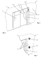
- Figs. 1 to 3 show possible applications of this invention.
- the advantage of this invention is that the user interface 3, independently of the direction of use of the user unit 7, is adjustable according to a selectable installation direction.
- Conventional user units 7 such as segment displays 8a, dot matrix displays 8, or a keyboard (eg, numeric keypad) 8c may be used, which are aligned according to a direction of use, while the housing 6 is alignable according to a desired installation direction. Since a same type of user interface 3 is adjustable to different directions of installation, it is correspondingly inexpensive to produce and it meets the aesthetic requirements.
- the user unit 7 includes a commercially available one Dot matrix display 8, a segment display 8a, a signal display 8b, a display or an input field 8c.
- the user unit 7 further contains for the operation of the Information or input devices required control units.
- the user unit 7 has a square, a polygonal or a round shape.
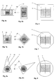
- the user unit 7 shown in FIG. 6 has a square shape and is correspondingly designed for a housing 6 whose installation direction can be selected from 90 ° steps.
- the user unit 7 shown in FIG. 7 has, for example, an octagonal shape and is designed accordingly for a housing 6 whose installation direction can be selected from 45 ° steps.
- the user unit 7 shown in FIG. 8 has a round shape and is designed accordingly for a housing 6 whose installation direction is free, or can be selected from any desired steps.
- a user interface 3 is provided according to requirements, which can be installed quickly and with little effort, and which takes into account special aesthetic requirements.
- the execution of the user unit 7 defines the free space.
- a cost-effective elevator it may well be sensible to offer only a minimal amount of free space, as this minimizes the effort involved in installing the user interface 3 in that no discussion is possible on the best aesthetically pleasing alignment.
- a luxurious environment it can make sense to offer a user interface 7 with the maximum possible freedom, since this allows consideration of special wishes, as shown in FIG. 8b.
- the housing 6 consists of a housing frame 9 and an at least partially transparent plate 10.
- the housing frame 9 forms the connection of the user unit 7, or an information or input device to a surrounding building or door part. It is designed according to the aesthetic and functional requirements.
- the at least partially transparent plate 10 together with the housing frame 9 forms an aesthetic unit.
- the at least partially transparent plate 10 may for example be a tinted or surface-coated glass or plastic plate, which makes the information of the display to the outside visible, but prevents direct insight into the interior of the housing 6.
- a mask is used instead of the plate.
- the mask is made of steel, for example, and has a hole or segment pattern corresponding to the display 8.
- this alternative is used in user interfaces 3 in which the mask is arranged according to the orientation of the user unit 7, as can be seen for example in FIGS. 8a and 8b.
- FIGS. 4 and 5 a Housing frame 9 realized in the form of a body frame or in Figs. 1 and Fig. 2 a housing frame 9 is shown in the form of a mounting frame with a flat shape.
- the user interface 3 can be installed substantially flush with the surrounding building or door part, wherein the required for the operation of the user interface devices in a corresponding space, or opening of the building or the door part are arranged.
- substantially flush means that the flat shape of the housing frame 9 is slightly recessed, flat or protruding the thickness of a flat mounting frame.
- the user unit 7 is directly connected to the housing 6.
- User unit 7 and housing 6 are assembled to an information top 11 completely.
- the information top 11 is completely, as shown in Fig. 9, mounted on a base plate 12 which is installed or mounted in a floor front 15.
- Advantageous effect of this arrangement is that the information part 11 can be assembled in a comfortable working position and is attached as a whole unit to the pre-assembled in the building base plate 12. This arrangement can be installed quickly and efficiently.
- the user unit 7 is connected to the base plate 12, and the housing 6 is fixed to the base plate 12.
- the user unit 7 is indirectly connected to the housing 6.
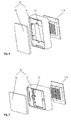
- the attachment of the user unit 7 in the housing 6 is advantageously carried out by means of Snap closure 13, as shown in Fig. 4 and Fig. 5.
- the user interface is thus constructed in such a way that the housing 6, the user unit 7, optically encloses and the housing 6 is connected to the user unit 7 in accordance with a selectable installation direction. It has a particularly advantageous effect that the installation direction of the user interface 3 can be selected up to the time of installation and that no further adjustment or adjustment work is required.
- the elevator expert can set the Change shapes and arrangements as you like. For example, he can the base plate 12th integrate directly into a component of the landing door or instead of snap closures 13 screwed connections can be used.
Landscapes
- Elevator Control (AREA)
Abstract
Description
Üblicherweise sind Benutzerinterfaces dementsprechend auf eine bestimmte, entweder vertikale oder horizontale Installationsrichtung des Benutzerinterfaces ausgelegt und hergestellt.
Das Benutzerinterface soll entsprechend einer wählbaren Installationsrichtung, möglichst unabhängig von der Gebrauchsrichtung der Eingabe- oder Informationsmodule, einstellbar sein und es sollen übliche Eingabe- oder Informationsmodule verwendet werden können. Im weiteren soll das Benutzerinterface kostengünstig herstellbar sein und ästhetisch ansprechend ausführbar sein.
Vorteilhafte Weiterbildungen der Erfindung sind in den Unteransprüchen dargestellt.
- Fig. 1
- Zeigt einen Etagenzugang mit einem im Zugangskämpfer angeordnetem, horizontal ausgerichtetem, Benutzerinterface,
- Fig. 2
- Zeigt einen Etagenzugang mit einem im Zugangspfosten angeordnetem, vertikal ausgerichtetem, Benutzerinterface,
- Fig. 3
- Zeigt einen Etagenzugang mit einer im Zugangsbereich angeordneter, vertikal ausgerichteten, Eingabeeinheit und einer, diagonal angeordneten, Informationseinheit,
- Fig. 4
- Zusammenbau eines Benutzerinterface in einer vertikalen Installationsrichtung,
- Fig. 5
- Zusammenbau eines Benutzerinterface in einer horizontalen Installationsrichtung,
- Fig. 6, 6a, 6b
- Schematische Anordnung einer quadratisch ausgeführten Benutzereinheit mit um 90° drehbarer Installationsrichtung,
- Fig. 7, 7a, 7b
- Schematische Anordnung einer achteckig ausgeführten Benutzereinheit mit um 45° drehbarer Installationsrichtung,
- Fig. 8, 8a, 8b
- Schematische Anordnung einer rund ausgeführten Benutzereinheit mit um 45° drehbarer Installationsrichtung,
- Fig. 9
- Zusammenbau eines Benutzerinterfaces mit Basisplatte,
- Fig. 10
- Ansicht einer Benutzereinheit mit einer Punktmatrix-Anzeige,
- Fig. 11
- Ansicht einer Benutzereinheit mit einer Segment-Anzeige,
- Fig. 12
- Ansicht einer Benutzereinheit mit einer Signal-Anzeige,
- Fig. 13
- Ansicht einer Benutzereinheit mit einer Eingabeeinheit.
Der Vorteil dieser Erfindung, besteht darin, dass das Benutzerinterface 3, unabhängig von der Gebrauchsrichtung der Benutzereinheit 7, entsprechend einer wählbaren Installationsrichtung einstellbar ist. Es können übliche Benutzereinheiten 7 wie beispielsweise Segmentanzeigen 8a, Punktmatrixanzeigen 8 oder eine Tastatur (z.B. Zehnertastatur) 8c verwendet werden, welche entsprechend einer Gebrauchsrichtung ausgerichtet sind, während das Gehäuse 6 entsprechend einer gewünschten Installationsrichtung ausrichtbar ist. Da ein gleicher Bautyp des Benutzerinterfaces 3 auf verschiedene Installationsrichtungen einstellbar ist, ist es entsprechend kostengünstig herstellbar und es erfüllt die ästhetischen Ansprüche.
Der Vorteil dieser Ausführungsarten liegt darin, dass anforderungsbezogen ein Benutzerinterface 3 bereitgestellt ist, welches schnell und mit wenig Aufwand installiert werden kann, und welches spezielle ästhetische Anforderungen berücksichtigt. Die Ausführung der Benutzereinheit 7 definiert dabei den Freiraum. So kann es in einem kostengünstigen Aufzug durchaus sinnvoll sein, lediglich einen minimalen Freiraum anzubieten, da dadurch der Aufwand bei der Installation des Benutzerinterfaces 3 insofern minimalisiert wird, dass keine Diskussion über eine ästhetisch beste Ausrichtung ermöglicht ist. Andererseits kann es in einem luxuriösen Umfeld durchaus sinnvoll sein, ein Benutzerinterface 7 mit maximal möglichen Freiraum anzubieten, da dies eine Berücksichtigung spezieller Wünsche ermöglicht wie in der Fig. 8b dargestellt.
In einer alternativen Lösung ist anstelle der Platte eine Maske verwendet. Die Maske ist beispielsweise aus Stahl gefertigt und weist ein, der Anzeige 8 entsprechendes, Loch- oder Segmentmuster auf. Vorzugsweise ist diese Alternative bei Benutzerinterfaces 3 verwendet, bei welchen die Maske entsprechend der Ausrichtung der Benutzereinheit 7 angeordnet ist, wie beispielsweise in den Fig. 8a und 8b erkennbar.
Der Vorteil dieser Ausführungsformen ist, dass sich bedarfsentsprechende Benutzerinterfaces 3 bereitstellen lassen welche die Anforderungen an die Ästhetik, Robustheit und Vandalismus hervorragend erfüllen und zugleich kostengünstig sind.
Vorteilhaft wirkt sich bei dieser Anordnung aus, dass der Informationsteil 11 in angenehmer Arbeitsposition zusammengebaut werden kann und als gesamte Einheit auf die im Gebäude vormontierte Basisplatte 12 befestigt wird. Diese Anordnung ist schnell und effizient montierbar.
Vorteilhaft bei dieser Anordnung ist, dass die Ausrichtung von Benutzereinheit 7 und des Gehäuses 6 unabhängig erfolgt. In einem ersten Schritt wird die Benutzereinheit 7 entsprechen der Gebrauchsrichtung montiert und anschliessend wird das Gehäuse 6 entsprechend der gewünschten Installationsrichtung angebracht. Dies vermindert Fehler in der Montage und ist dementsprechend effizient.
Mit der gezeigten Befestigung ist eine schnelle und effiziente Montage des Benutzerinterfaces 3 möglich und die Montage kann im wesentlichen ohne Werkzeuge erfolgen.
Besonders vorteilhaft wirkt sich dabei aus, dass die Installationsrichtung des Benutzerinterfaces 3 bis zum Zeitpunkt der Montage gewählt werden kann und, dass keinerlei weitere Einstell- oder Justierarbeiten erforderlich sind.
Claims (9)
- Benutzerinterface zu einer Aufzugsanlage (1), zumindest bestehend aus einem Gehäuse (6) und einer Benutzereinheit (7), wobei das Gehäuse (6) mit der Benutzereinheit (7) verbunden ist und das Gehäuse (6) einen sichtbaren Übergang von der Benutzereinheit (7) zum umgebenden Gebäude bildet, dadurch gekennzeichnet, dass das Gehäuse (6) entsprechend einer wählbaren Installationsrichtung mit der Benutzereinheit (7) verbunden ist.
- Benutzerinterface gemäss Anspruch 1, dadurch gekennzeichnet, dass die Benutzereinheit (7) eine Punktmatrix-Anzeige (8), eine Segmentanzeige (8a), eine Signalanzeige (8b), ein Display oder ein Eingabefeld (8c) enthält.
- Benutzerinterface gemäss Anspruch 1 oder 2, dadurch gekennzeichnet, dass die Installationsrichtung aus beliebigen Schritten wählbar ist, oder dass die Installationsrichtung aus 45° oder 90° Schritten wählbar ist.
- Benutzerinterface gemäss einem der Ansprüche 1 bis 3, dadurch gekennzeichnet, dass das Gehäuse (6) aus einem Gehäuserahmen (9) und einer zumindest teilweise durchsichtigen Platte (10) oder einer Maske besteht und dass der Gehäuserahmen (9) ein Aufbaurahmen oder ein Einbaurahmen ist.
- Benutzerinterface gemäss Anspruche 4, dadurch gekennzeichnet, dass die Benutzereinheit (7) mit dem Gehäuse (6) einen Informationsoberteil komplett (11) bildet, welcher auf eine Basisplatte (12) befestigt ist, oder welcher in eine Etagenfront (15) eingebaut ist.
- Benutzerinterface gemäss Anspruch 4, dadurch gekennzeichnet, dass die Benutzereinheit (7) mit einer Basisplatte (12) verbunden ist, und das Gehäuse (6) auf die Basisplatte(12) befestigt ist.
- Benutzerinterface gemäss einem der Ansprüche 1 bis 6, dadurch gekennzeichnet, dass die Benutzereinheit (7) mittels Schnappverschluss (13) mit dem Gehäuse (6) verbunden ist.
- Benutzerinterface gemäss einem der Ansprüche 1 bis 7, dadurch gekennzeichnet, dass das Gehäuse (6), oder der Informationsoberteil komplett (11) mittels Federklemmen (14) auf die Basisplatte oder die Etagenfront verbunden ist.
- Verfahren zur Installation eines Benutzerinterfaces zu einer Aufzugsanlage bestehend aus einem Gehäuse (6) und einer Benutzereinheit (7), wobei das Gehäuse (6) mit der Benutzereinheit (7) verbunden ist und das Gehäuse (6) einen sichtbaren Übergang von der Benutzereinheit (7) zum umgebenden Gebäude bildet, dadurch gekennzeichnet, dass das Gehäuse (6) entsprechend einer wählbaren Installationsrichtung mit der Benutzereinheit (7) verbunden wird.
Priority Applications (1)
| Application Number | Priority Date | Filing Date | Title |
|---|---|---|---|
| EP05000448A EP1609753A1 (de) | 2004-01-22 | 2005-01-12 | Benutzerinterface für eine Aufzugsanlage |
Applications Claiming Priority (3)
| Application Number | Priority Date | Filing Date | Title |
|---|---|---|---|
| EP04405043 | 2004-01-22 | ||
| EP04405043 | 2004-01-22 | ||
| EP05000448A EP1609753A1 (de) | 2004-01-22 | 2005-01-12 | Benutzerinterface für eine Aufzugsanlage |
Publications (1)
| Publication Number | Publication Date |
|---|---|
| EP1609753A1 true EP1609753A1 (de) | 2005-12-28 |
Family
ID=35427091
Family Applications (1)
| Application Number | Title | Priority Date | Filing Date |
|---|---|---|---|
| EP05000448A Withdrawn EP1609753A1 (de) | 2004-01-22 | 2005-01-12 | Benutzerinterface für eine Aufzugsanlage |
Country Status (1)
| Country | Link |
|---|---|
| EP (1) | EP1609753A1 (de) |
Cited By (2)
| Publication number | Priority date | Publication date | Assignee | Title |
|---|---|---|---|---|
| US7835771B2 (en) | 2001-03-02 | 2010-11-16 | Nokia Corporation | Method and apparatus for combining properties in mobile station |
| WO2022002703A1 (de) * | 2020-06-30 | 2022-01-06 | Inventio Ag | Aufzugsanlage |
Citations (2)
| Publication number | Priority date | Publication date | Assignee | Title |
|---|---|---|---|---|
| EP0449077A2 (de) * | 1990-03-26 | 1991-10-02 | KONE Elevator GmbH | Stockwerks-und Richtungsanzeigegerät für einen Aufzug |
| US5460118A (en) * | 1993-08-13 | 1995-10-24 | Inventio Ag | Surface mounted modular signal device for elevators |
-
2005
- 2005-01-12 EP EP05000448A patent/EP1609753A1/de not_active Withdrawn
Patent Citations (2)
| Publication number | Priority date | Publication date | Assignee | Title |
|---|---|---|---|---|
| EP0449077A2 (de) * | 1990-03-26 | 1991-10-02 | KONE Elevator GmbH | Stockwerks-und Richtungsanzeigegerät für einen Aufzug |
| US5460118A (en) * | 1993-08-13 | 1995-10-24 | Inventio Ag | Surface mounted modular signal device for elevators |
Cited By (6)
| Publication number | Priority date | Publication date | Assignee | Title |
|---|---|---|---|---|
| US7835771B2 (en) | 2001-03-02 | 2010-11-16 | Nokia Corporation | Method and apparatus for combining properties in mobile station |
| WO2022002703A1 (de) * | 2020-06-30 | 2022-01-06 | Inventio Ag | Aufzugsanlage |
| WO2022002704A1 (de) * | 2020-06-30 | 2022-01-06 | Inventio Ag | Aufzugsanlage |
| CN115734929A (zh) * | 2020-06-30 | 2023-03-03 | 因温特奥股份公司 | 电梯设备 |
| US12091284B2 (en) | 2020-06-30 | 2024-09-17 | Inventio Ag | Elevator system |
| US12139373B2 (en) | 2020-06-30 | 2024-11-12 | Inventio Ag | Elevator system |
Similar Documents
| Publication | Publication Date | Title |
|---|---|---|
| EP3242539B1 (de) | Vorrichtung zur integration eines bildschirms oder monitors in ein gehäuse | |
| WO2007031366A1 (de) | Anzeigesystem insbesondere für eine industrielle automatisierungseinrichtung | |
| EP2206132B1 (de) | Betätiger | |
| EP3287063A1 (de) | Elektrogerät, anordnung eines solchen elektrogeräts mit einer blende und verfahren zur herstellung einer solchen anordnung | |
| DE60309786T2 (de) | Anzeigevorrichtung mit Anzeigetafel | |
| DE3440763A1 (de) | Lenkstockschalter fuer kraftfahrzeuge | |
| EP0388728A2 (de) | Herdblende. | |
| DE29603765U1 (de) | Computergehäuse | |
| EP0951117A1 (de) | Fenstereinheit | |
| EP0158723A1 (de) | Bildschirmgerät | |
| DE10064534A1 (de) | Anzeigevorrichtung für Fassaden-Displays | |
| DE10035044A1 (de) | Kommunikationsvorrichtung | |
| EP0938071B1 (de) | Anzeigevorrichtung und Transportfahrzeug mit Anzeigevorrichtung | |
| EP3715300A1 (de) | Eingabevorrichtung für aufzüge | |
| DE19851337B4 (de) | Anordnung zur Darstellung einer Oberfläche | |
| DE19737058C1 (de) | Bildschirmgerät mit einem Flachdisplay | |
| EP1209715A2 (de) | Frontscheibe zur Abschirmung eines Plasma-Flachbildschirms | |
| EP2200293B1 (de) | Elektronisches Gerät mit einem Anzeigemodul | |
| EP4727274A1 (de) | Interaktionsmodul für ein schaltschrankloses automatisierungssystem einer industrieanlage | |
| DE202005018658U1 (de) | Elektrische Schaltervorrichtung | |
| DE102004014935B3 (de) | Bedienteil für Installationstechnik | |
| DE102008024849A1 (de) | Schalteranordnung | |
| DE202023104308U1 (de) | Mensch-Maschine-Schnittstellenmodul | |
| DE102005062492B4 (de) | Elektrisches/elektronisches Installationsgerät | |
| DE20119900U1 (de) | Anordnung aus einem Sichtgerät und einem PC-basierten Gerät |
Legal Events
| Date | Code | Title | Description |
|---|---|---|---|
| PUAI | Public reference made under article 153(3) epc to a published international application that has entered the european phase |
Free format text: ORIGINAL CODE: 0009012 |
|
| AK | Designated contracting states |
Kind code of ref document: A1 Designated state(s): AT BE BG CH CY CZ DE DK EE ES FI FR GB GR HU IE IS IT LI LT LU MC NL PL PT RO SE SI SK TR |
|
| AX | Request for extension of the european patent |
Extension state: AL BA HR LV MK YU |
|
| 17P | Request for examination filed |
Effective date: 20060623 |
|
| AKX | Designation fees paid |
Designated state(s): AT BE BG CH CY CZ DE DK EE ES FI FR GB GR HU IE IS IT LI LT LU MC NL PL PT RO SE SI SK TR |
|
| REG | Reference to a national code |
Ref country code: HK Ref legal event code: DE Ref document number: 1086244 Country of ref document: HK |
|
| STAA | Information on the status of an ep patent application or granted ep patent |
Free format text: STATUS: THE APPLICATION HAS BEEN WITHDRAWN |
|
| 18W | Application withdrawn |
Effective date: 20161128 |
|
| REG | Reference to a national code |
Ref country code: HK Ref legal event code: WD Ref document number: 1086244 Country of ref document: HK |