EP1609714B1 - Pignon pour bicyclette - Google Patents
Pignon pour bicyclette Download PDFInfo
- Publication number
- EP1609714B1 EP1609714B1 EP05012459A EP05012459A EP1609714B1 EP 1609714 B1 EP1609714 B1 EP 1609714B1 EP 05012459 A EP05012459 A EP 05012459A EP 05012459 A EP05012459 A EP 05012459A EP 1609714 B1 EP1609714 B1 EP 1609714B1
- Authority
- EP
- European Patent Office
- Prior art keywords
- sprocket
- tubular member
- synthetic resin
- fastening part
- metallic tubular
- Prior art date
- Legal status (The legal status is an assumption and is not a legal conclusion. Google has not performed a legal analysis and makes no representation as to the accuracy of the status listed.)
- Revoked
Links
Images


Classifications
-
- B—PERFORMING OPERATIONS; TRANSPORTING
- B62—LAND VEHICLES FOR TRAVELLING OTHERWISE THAN ON RAILS
- B62M—RIDER PROPULSION OF WHEELED VEHICLES OR SLEDGES; POWERED PROPULSION OF SLEDGES OR SINGLE-TRACK CYCLES; TRANSMISSIONS SPECIALLY ADAPTED FOR SUCH VEHICLES
- B62M9/00—Transmissions characterised by use of an endless chain, belt, or the like
- B62M9/04—Transmissions characterised by use of an endless chain, belt, or the like of changeable ratio
- B62M9/06—Transmissions characterised by use of an endless chain, belt, or the like of changeable ratio using a single chain, belt, or the like
- B62M9/10—Transmissions characterised by use of an endless chain, belt, or the like of changeable ratio using a single chain, belt, or the like involving different-sized wheels, e.g. rear sprocket chain wheels selectively engaged by the chain, belt, or the like
- B62M9/105—Transmissions characterised by use of an endless chain, belt, or the like of changeable ratio using a single chain, belt, or the like involving different-sized wheels, e.g. rear sprocket chain wheels selectively engaged by the chain, belt, or the like involving front sprocket chain-wheels engaged by the chain, belt or the like
Definitions
- the present invention generally relates to a bicycle sprocket. More specifically, the present invention relates to a bicycle sprocket configured to be mounted to a rotational drive unit such as a crank of a bicycle via a synthetic resin fastening part and to have a bicycle (drive-purpose) chain wrapped around the outside circumference of a sprocket ring part thereof.
- a rotational drive unit such as a crank of a bicycle via a synthetic resin fastening part
- a bicycle is generally provided with a drive unit or drive train having front and rear sprockets and a chain wrapped around the sprockets.
- the front sprocket(s) is provided on the gear crank of the bicycle and the rear sprocket(s) is provided on the free hub of the bicycle.
- This type of bicycle sprocket is made of such materials as the aluminum having the designation A2014P under the standard JIS H4000 (category) or the iron having the designation SPCC under the standard JIS G3141 (category).
- aluminum is used as the material in order to reduce the weight.
- a gap is provided between the sprocket ring part and the fastening part in order to prevent deformation caused by the effects of weather.
- mounting holes with steps are formed in the fastening part of the gear crank.
- a bolt an example of fixed member
- the sprocket is fixed to a spider arm of the gear crank via the bolt and the fastening part.
- FR 2 615 473 discloses a sprocket assembly according to the preamble of claim 1.
- One object of the present invention is to provide a bicycle sprocket that is constructed of two different materials, which is light weight, maintains rigidity, prevents looseness or play, and can be fabricated with a simplified manufacturing process.
- Another object of the present invention is to provide a bicycle sprocket that prevents a reduction in attachment forces or the attachment strength because of age deterioration of the synthetic resin fastening part, and/or because of deformation of the synthetic resin fastening part.
- the bicycle sprocket according to the first aspect of the present invention includes a sprocket ring part and a synthetic resin fastening part.
- the sprocket ring part includes an inner periphery and an outer periphery with a plurality of sprocket teeth arranged on the outer periphery.
- the sprocket ring part extends around a central rotation axis.
- the synthetic resin fastening part is non-movably coupled to the sprocket ring part at a location radially inwardly of the sprocket teeth relative to the rotation axis.
- the synthetic resin fastening part includes at least one through hole with a metallic tubular member mounted therein and configured to be fixedly coupled to a rotational drive unit of a bicycle.
- the metallic tubular member has a first fastener contact surface configured and arranged to receive a fastening force.
- This synthetic resin fastening part has a mounting hole, and the metallic tubular (tubelike) member is mounted in the mounting hole.
- a fixed member, such as a bolt, is passed through this tubular member to fix the sprocket to the rotational drive unit of the bicycle (turning drive member).
- the metallic tubular member is non-movable relative to the synthetic resin fastening part in an axial direction substantially parallel to the central rotation axis.
- the tubular member is mounted in the mounting hole to become unmovable along the direction of the axis.
- the attachment force from a fixed member such as a bolt can be reliably (certainly) received by the first contact surface.
- the synthetic resin fastening part is at least partially integrally molded around the metallic tubular member to prevent movement of the metallic tubular member relative to the synthetic resin fastening part (e.g. especially in the axial direction).
- the tubular member is formed with the fastening part.
- the tubular member since the tubular member has the synthetic resin fastening part at least partially molded/formed around it, such as by insert forming, it can be easily mounted to become unmovable along the direction of the axis.
- the metallic tubular member includes a flange section extending outwardly therefrom relative to a central through axis of the metallic tubular member, the first contact surface being formed on the flange section.
- the tubular member has a tubular part and a guard part larger than the tubular part, and the first contact surface is set up on the guard part.
- the tubular member can be mounted in the fastening part to become unmovable along the direction of the axis, and the first contact surface can be arranged to contact the fixed member such as a bolt at the relatively larger guard part, the area of the first contact surface gets larger, and the pressure on the first contact surface gets less (per unit area) even if it receives power from the fixed member such as a bolt.
- both parts can be powerfully held (strongly formed) by putting the guard part into the inner member.
- the metallic tubular member includes a second contact surface that is configured and arranged to contact the rotational drive unit.
- the tubular member has the second contact surface that contacts the turning drive member.
- the sprocket ring part includes a pair of sides and the synthetic resin fastening part is at least partially integrally molded around both sides of the sprocket ring part.
- the sprocket ring part is metallic, and the fastening part is formed with (i.e. partially around) both sides of the sprocket ring part.
- the fastening part is placed on the both sides of the sprocket ring part so that the rigidity between the sprocket ring part and the fastening part can be maintained.
- the manufacturing process can be simplified.
- the bicycle sprocket further comprises a fastening member with an enlarged head that is sized and configured to contact the first fastener contact surface to apply the fastening force.
- the fastening member is preferably a bolt with a threaded shaft and the enlarged head arranged at one end of the threaded shaft.
- the fixed member is a bolt that has a head, and the tubular member contacts the head of the bolt. In this case, even if the head of the bolt contacts the first contact surface of the tubular member, the first contact surface is hardly deformed.
- the sprocket ring part includes a first anchor structure and the synthetic resin fastening part includes a second anchor structure that cooperates with the first anchor structure to prevent relative movement therebetween.
- the sprocket ring part additionally has an anchoring means to unrotatably connect the fastening part thereto.
- the sprocket ring part and the fastening part are unrotatably connected by the anchor means so that rigidity/strength is increased.
- the synthetic resin fastening part is constructed of a polyamide based-based synthetic resin with a carbon fiber filler impregnated therein.
- the fastening part is made of carbon fiber resin incorporation that impregnates a carbon fiber filler with polyamide based synthetic resin.
- the strength of the fastening part can be stronger by impregnating carbon fiber than with synthetic resin alone (not including the carbon fiber impregnation).
- the sprocket ring part is constructed of an aluminum alloy that has an anodic oxide layer formed on the surface thereof.
- the sprocket ring part is made of aluminum base alloy that has anodized, oxidized porous aluminum, and/or an alumilite layer formed on its surface. In this case, the corrosion resistence of the sprocket ring part is improved.
- the metallic tubular member is constructed of an aluminum alloy.
- the tubular member is made of an aluminum base alloy. In this case, even if the tubular member is mounted to prevent deforming of the fastening part, weight savings can be facilitated.
- the metallic tubular member which is more difficult to be deteriorated with age than synthetic resin, is mounted in the fastening part, and the first contact surface of the tubular member receives power (axial force) from the fixed member such as a bolt.
- relatively soft synthetic resin i.e. softer than commonly used metallic materials
- the fixed portion of the fastening part that is fixed to the turning drive member is hardly deformed, and lowering of the fixing forces (power) due to deterioration of synthetic resin and/or deforming can be minimized and/or prevented. Accordingly, weight saving of the sprocket can be facilitated with adversely affecting other characteristics and/or performance of the sprocket.
- FIG. 1 a bicycle 10 is illustrated in accordance with a first embodiment of the present invention.
- Figure 1 shows a road bike 10 having a drop-type handlebar unit 14.
- the road bike 10 has a diamond-shaped frame 11 that serves as the framework of the bicycle body.
- the frame 11 has a frame body 12 and a front fork 13.
- the front fork 13 is supported on a front part of the frame 12 such that it can rotate freely about an axis that is tilted slightly from vertical.
- the lower part of the front fork 13 is divided into two prongs.
- the bicycle 10 is also provided with the handlebar unit 14 connected to the front fork 13, and in addition a drive unit or drive train 15, a front wheel 16, a rear wheel 17 and front and rear brake devices 18 and 19.
- the drive train 15 is configured to convert the rider's pedaling force into driving force.
- the front wheel 16 is supported in a freely rotatable manner on the bottom end of the front fork 13 between the prongs.
- the rear wheel 17 is supported in a freely rotatable manner on a rear part of the frame body 12.
- the frame body 12 has a triangular shaped main or front triangle 20 and a rear triangle 21 arranged rearward of the front triangle 20.
- the front triangle 20 is formed by a top tube 25, a down tube 26, head tube 27 and a seat tube 28.
- the top tube 25 is arranged generally horizontally, while the down tube 26 is arranged below the top tube 25 such that it slants upward toward the front.
- the head tube 27 is joined to the front ends of the top tube 25 and the down tube 26, while the seat tube 28 extends diagonally upward and is joined to the rear ends of the top tube 25 and down tube 26.
- a seat post 33 having a saddle 32 fastened thereto is secured in the seat tube 28 in such a manner that its position can be adjusted up and down.
- a cylindrical hanger 29 ( Figure 3 ) is formed at the portion where the seat tube 28 and the down tube 26 join.
- the rear triangle 21 is formed by a pair of seat stays 30, a pair of chain stays 31 and the seat tube 28.
- the seat stays 30 are joined at their front ends to the seat tube 28 and extend diagonally downward as two separate prongs.
- the chain stays 31 extend rearward as two separate prongs from the bottom end of the seat tube 28
- the handlebar unit 14 includes a handlebar stem 35 that is fastened to the upper part of the front fork 13 in such a manner that its vertical position can be selectively adjusted up and down relative to the front fork 13.
- a handlebar 36 extends to the left and right and is curved at both ends.
- the handlebar 36 is fastened to the top end of the handlebar stem 35.
- a pair of braking devices 38 that are provided with gear shifting capability are mounted to opposite ends of the handlebar 36.
- the drive unit or drive train 15 includes a front crank set or crank unit 41, a rear sprocket assembly or small gear unit 43, a chain 44, a front derailleur 45 and a rear derailleur 46.
- the crank set (crank unit) 41 is mounted on the hanger 29.
- the rear sprocket assembly (small gear unit) 43 mounted in a non-rotatable manner to the free hub or free wheel of the rear wheel 17.
- the chain 44 is arranged on the crank set (gear crank unit) 41 and the rear sprocket assembly (small gear unit) 43 so as to extend therebetween.
- the front derailleur 45 is coupled to the seat tube 28, while the rear derailleur 46 is coupled to the rear triangle 21.
- the derailleur 45 and 46 function as a means of changing gears.
- the front derailleur 45 has a chain guide 45a through which the chain 44 passes.
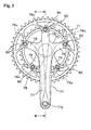
- the crank set (crank unit) 41 basically includes a crank shaft 50 ( Figure 3 ), a right crank arm (gear crank) 51 and a left crank arm (left crank) 52.
- the crank shaft 50 is supported in a freely rotatable manner in the hanger 29 of the frame 11.
- the right crank arm 51 is crimp-fastened to the right end of the crank shaft 50 and has a pedal 53 ( Figure 1 ) mounted to its tip end, while the left crank arm 52 ( Figure 3 ) is fastened in a detachable manner to the left end of the crank shaft 50 with another pedal (that is a mirror image of the pedal 53) mounted to its tip end such that the rider can provide a pedaling force to the drive train 15, as best seen in Figure 1 .
- crank shaft 50 is mounted in a freely rotatable manner in the hanger 29 by means of a bottom bracket 54 mounted in the hanger 29 for rotation about a central rotation axis X.
- crankset 41 is freely rotatable about the central rotation axis X.
- the crank shaft 50 is a hollow pipe-shaped member made of a high-rigidity alloy, such as chromium-molybdenum steel.
- the radially inwardly facing surface of the left end of crank shaft 50 is provided with internal threads 55b so that the left crank arm 52 can be fastened thereto with a bolt 59.
- the bottom bracket 54 includes a left and right bearing housings 60 and 61, a cylindrical linking member 62, left and right ball bearings 63 and 64, and left and right cover members 65 and 66.
- the left and right bearing housings 60 and 61 are screwed into the ends of the hanger 29.
- the cylindrical linking member 62 is concentric with and connects mates to the left and right bearing housings 60 and 61 via a pair of additional bearings.
- the left and right ball bearings 63 and 64 are mounted in the left and right housings 60 and 61, respectively.
- the left and right cover members 65 and 66 are mounted between the crank shaft 50 and the inner rings (races) of the left and right ball bearings 63 and 64, respectively.
- the ball bearings 63 and 64 are sealed bearings having seals installed between the inner ring (race) and the outer ring (race) and are injected with grease in advance of assembling the bottom bracket 54. Consequently, lubrication maintenance can be eliminated. Arranging the bearings 63 and 64 outside the hanger 29 enables the diameter of the crank shaft 50 to be increased and, as a result, the crank shaft 50 can be made lighter in weight while maintaining high strength and rigidity by making the crank shaft 50 hollow.
- the right crank arm (gear crank) 51 includes a crank connecting part or portion 75, five support arm parts or portions 76 and a main right crank arm part or portion 77.
- the crank connecting portion 75 has an engagement depression 78 that forms a circular space and mounts in a non-rotatable manner to the right end of the crank shaft 50.
- the five support arm portions 76 extend radially outwardly from the crank connecting portion 75 and are configured such that two sprockets 71 and 72 (one large and one small, respectively) can be mounted on the tip ends thereof.
- the main crank arm portion 77 is preferably integrally formed with the crank connecting portion 75 and the five support arm portions 76 such that the right main crank arm portion 77 fixed to the right end of the crank shaft 50.
- the tip ends of the support arm portions 76 are provided with mounting sections (parts) 76a for attaching the sprockets 71 and 72 thereto.
- the mounting sections 76a are recessed on opposite axial sides thereof relative to the other portions to form radially outwardly facing abutment surfaces.
- the sprockets 71 and 72 are mounted on both (opposite) sides of the mounting sections 76a in such a manner that the sprockets 71 and 72 are concentric with respect to the crank shaft 50 and the central rotation axis X.
- each of the mounting sections 76a is provided with a first fastening hole 76b that extends in an axial direction.
- the sprockets 71 and 72 can be fastened simultaneously to the mounting sections 76a with (five) bolts 80 and nuts 81.
- the right main crank portion 77 has a hollow structure and is formed integrally with the crank connecting portion 75 and the support arm portions 76.
- the right crank portion 77 extends radially outwardly, while slanting slightly outward in the axial direction from the outside surface 75a of the crank connecting portion 75.
- a threaded pedal mounting hole 77a is provided in the extended tip end of the right main crank portion 77 for installing the pedal 53.
- the engagement depression 78 of the crank connecting portion 75 is mounted to the second portion 56 of the crank shaft 50.
- the engagement depression 78 is formed to a length (i.e., depth) that is larger than the length of the second portion 56 and reaches almost to the outside surface 75a.
- the outside surface 75a of the crank connecting portion 75 and the main right crank portion 77 is smoothly curved and free of irregularities.
- the depth of the engagement depression 78 is shorter than the diameter of the second portion 56 of the crank shaft 50.
- the sprocket 71 in accordance with a preferred embodiment of the present invention basically includes a sprocket ring part 90, a fastening part 91 and a plurality (five) of tubular members 92.
- the sprocket ring part 90 and the tubular members 92 are constructed of metal (e.g. aluminum alloy), while the fastening part 91 is constructed of synthetic resin, formed integrally with (partially around) the sprocket ring part 90 and the tubular members 92.
- the construction of the sprocket 71 in accordance with the present invention will be explained in more detail below.
- the fastening part 91 is fastened to the right crank arm 51 ( Figures 2 and 3 ) using the tubular members 92 as also explained in more detail below.
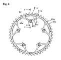
- the sprocket ring part 90 is a ring-shaped member having multiple (i.e. a plurality of) sprocket teeth 90a formed on the outside circumference thereof upon which the chain 44 ( Figure 1 ) is wrapped. As shown in Figure 6 , multiple (i.e. a plurality of) circumferentially spaced through holes 90d are provided that extend between (first and second) lateral sides or side surfaces 90b and 90c of the sprocket ring part 90. Preferably, through holes 90d are arranged around the entire circumference of the sprocket ring part 90. The through holes 90d form a first anchor structure (means) for rigidly connecting the fastening part 91 in a non-rotatable manner.
- first anchor structure means
- the synthetic material of the fastening part 91 extends through the holes 90d to form a second anchor structure that cooperates with the first anchor structure to prevent relative movement therebetween.
- the sprocket ring part 90 is preferably constructed by die punching a metal plate into the ring shape having sprocket teeth 90a formed on the outside circumference thereof and the through holes 90d extending between both lateral faces 90b and 90c thereof.
- the fastening part 91 is preferably constructed of a polyamide-based synthetic resin impregnated with a reinforcing material such as a carbon fiber filler.
- the fastening part 91 is formed integrally around both lateral sides or side surfaces 90b and 90c of the sprocket ring part 90 at an area of the sprocket ring part 90 located radially inward of where the sprocket teeth 90a are formed.
- the fastening part 91 has a ring section (part) 91a and a screw fastening section (part) 91b.
- the ring section 91a is molded integrally (partially) around and through the sprocket ring part 90 (i.e. through the through holes 90d).
- the screw fastening section 91b extends radially inward from the ring section 91a.
- the screw fastening section 91b has a plurality of second fastening holes positioned such that they can be aligned with the first fastening holes 76b.
- the ring section 91 a is formed integrally such that it substantially covers both lateral faces 90b and 90c as well as the radially inwardly facing surface 90e of the sprocket ring part 90.
- the screw fastening section (part) 91b is preferably molded integrally (partially) around the tubular members 92, as explained below.
- the screw fastening section 91b has a plurality (five) of arch elements (parts) 91c that extend radially inwardly from the radially inward facing surface of the ring section 91 a to form a plurality (five) arm fastening flanges (parts) 91d formed on a middle portion of each arch element 91 c.
- the arm fastening flanges 91d are positioned to be aligned face to face with the mounting sections 76a on the tip ends of the support arm portions 76.
- Each fastening flange 91d includes and axially extending (stepped) mounting hole 91e that is arranged to be aligned with one of the first fastening holes 76b.
- the stepped shape of the mounting holes is due to the fastening part 91 being at least partially molded around the tubular members 92.
- the tubular members 92 are mounted to be unmovable relative to the fastening part.
- the tubular members 92 are mounted to be unmovable along the axial direction (i.e. substantially parallel to the central rotation axis X) in the mounting holes 91e.
- the tubular members 92 are preferably constructed of an aluminum (base) alloy. Each tubular member 92 includes a tubular part 92a and a flange section (guard part) 92b extending outwardly from the tubular part 92a relative to a central through axis of the metallic tubular member 92. The flange section 92b is larger than the tubular part 92a.
- the tubular members 92 are preferably identical and preferably attached to the fastening part 91 in and identical manner. Thus, only one of the tubular members 92 will be explained and/or illustrated in detail herein.
- the flange section (guard part) 92b has a first annular axially facing fastener contact surface 92c formed on the outer axial end to receive power (an axial fastening force) from one of the bolts 80 by contacting a head part 80a of one of the bolts 80.
- the outer circumferential part of the flange section 92b is fitted in an inner (annular) circumferential groove of one of the stepped mounting holes 91 e.
- the outer circumferential parts of the flange sections 92b form inner circumferential grooves of the stepped mounting holes 91 e when the fastening part 91 is molded around the outer circumferential parts of the flange sections 92b.
- each of the tubular parts 92a has a second annular axially facing contact surface 92d that contacts one of the mounting sections (parts) 76a of the right crank arm (gear crank) 51 on the outwardly axially facing surface thereof.
- the tubular member 92 and the fastening part 91 are hardly deformed even if a large power affect from a chain is applied, or if the bolt 80 is tightened with too much torque.
- the second contact surface 92d of the metallic tubular member 92 contacts with the mounting section (part) 76a so that the power affects and/or axial tightening forces are applied (i.e. transferred through) the metallic tubular member 92 instead of the synthetic resin fastening part 91 when the sprocket 71 is fixed by the bolts 80. Because of this arrangement, the portions of the fastening part 91 that are fixed with the mounting sections (part) 76a are hardly deformed.
- the bolts 80 are installed from the second fastening hole 91e side and fastened with nuts 81 from the first fastening hole 76b (i.e. the opposite side) side such that the two sprockets 71 and 72 are fixed to opposite faces or sides of the mounting sections 76a.
- the bolts 80 are hollow bolts having enlarged heads with hexagonal sockets and threaded shafts extending therefrom, and the nuts 81 are hollow nuts each having a flange.
- the bolts 80 and nuts 81 are well-known items used for positioning and fastening front sprockets.
- the two sprockets 71 and 72 are fixed on opposite sides of the mounting sections (parts) 76a by the nuts 81 that are mounted from the (inner) side of the sprocket 72 and the bolts 80 that are mounted from the opposite (outer) side of the sprocket 71 (adjacent the flange sections 92b of the tubular members 92 of the sprocket 71).
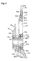
- the sprocket 71 is manufactured using a process like that shown in Figure 7 in accordance with the present invention. In order to simplify the drawings of Figure 7 , only a portion of the ring section 91a and one of the screw fastening sections 91b of the fastening part 91 is shown. The manufacturing process for the sprocket 71 of the present invention will now be discussed in more detail.
- an aluminum (base) alloy plate is die punched to obtain a sprocket ring part 90 shaped as shown in Figures 4 and 6 in a conventional manner.
- an anodic oxide layer e.g. an anodized, oxidized porous aluminum, and/or alumilite layer
- a continuous annular diffusion layer 93a of a fine triazine thiol powder is then formed on both lateral faces 90b and 90c and the inner circumference 90e of the sprocket ring part 90 using an electro deposition method.
- a diffused layer 93b of a fine triazine thiol powder is also formed on the outer circumference surface of the flange section (guard part) 92b and tubular part 92a of the tubular members 92.
- Each of these surface treatments are well known in the metal working/treating arts. Thus, each of these surface treatments will not be discussed and/or illustrated in detail herein, except as related to the present invention.
- the sprocket ring part 90 and the tubular members 92 on which the diffusion layers 93a and 93b have been formed are then inserted into a mold 95 having an upper die 95a and a lower die 95b for molding the fastening part 91.
- the inside of the mold 95 holds the radially outermost area of the sprocket ring part 90 (i.e. the sprocket teeth 90a and the area slightly radially inwardly thereof), while forming a space 95c for forming the fastening part 91 (the ring section 91 a) therearound.
- the inside of the mold 95 holds the inner circumferential area of each tubular member 92 to form a space 95d for forming the fastening part 91 (screw fastening sections 91b) therearound.
- the mold 95 is closed (fastened) and the internal spaces 95c and 95d are filled with a molten polyamide-based synthetic resin that has been impregnated with a reinforcing material such as carbon fiber filler.
- the synthetic resin and the diffusion layers 93a and 93b undergo a chemical reaction such that the fastening part 91 is chemically bonded together with the sprocket ring part 90 and the tubular members.
- the sprocket ring part 90 and the fastening part 91 are fixed together by molding the fastening part 91 integrally (i.e., chemically, adhesively fixing) to both lateral faces 90b and 90c of the sprocket ring part 90, looseness can be prevented and a high rigidity can be maintained between the sprocket ring part 90 and the fastening part 91. Additionally, the manufacturing process can be simplified because it is not necessary to provide a riveting step for installing rivets and/or crimp pins and a crimping step crimping them. Furthermore, the weight of the sprocket can be reduced because the fastening part 91 is made of a synthetic resin.
- the portion of the fastening part 91 that is fixed with the mounting sections (parts) 76a is hardly deformed, lowering of the fixing/fastening power due to deterioration of synthetic resin or deformation can be prevented, and weight saving of the sprocket 71 can be facilitated.
- backlash of the mounting sections (parts) 76a due to deterioration or deformation can be also prevented.
- the sprocket 72 has a ring part 72b with a plurality of sprocket teeth 72a extending outwardly therefrom and a fastening part 72c that is integrally formed with the ring part 72b as a one-piece, unitary member.
- the fastening part 72c projects radially inward from the inner circumference of the ring part 72b.
- the sprocket 72 is constructed of a metallic material (for example, aluminum) using a well-known sprocket design and manufacturing techniques.
- the fastening part 72c of the sprocket 72 and the fastening part 91 of the sprocket 71 are fastened simultaneously to the support arm portions 76.
- the left crank arm 52 has a hollow-structured left main crank arm part or portion 85 provided with a pedal mounting hole 85a for screw-installing a pedal 53 on the tip end thereof.
- the left crank arm 52 is provided with a slit (not shown) in the inner end thereof that mounts to the crank shaft 50.
- the left crank arm 52 is fastened securely to the crank shaft 50 by tightening two mounting bolts 57a and 57b (which are arranged in positions shown below the crank shaft 50 in Figure 3 ) such that the slit narrowed.
- the two mounting bolts 57a and 57b are, for example, hexagonal socket bolts inserted with their heads facing in opposite directions, respectively.
- the sprockets 71 and 72 are first mounted to the right crank arm 51.
- the sprockets 71 and 72 are 72 are arranged in the recessed areas of the mounting sections 76a such that the respective fastening holes 76b and 91e are aligned face to face with each other.
- the bolts 80 are installed from the sprocket 71 side (i.e., the outside) and the nuts are installed from the sprocket 72 side (i.e., the inside) as best understood from Figures 3 and 5 .
- the sprockets 71 and 72 are then secured by turning the bolts 80 using an Allen wrench (key) while preventing the nuts 81 from turning using a special tool.
- the right crank arm 51 is crimp-fastened to the crank shaft 50.
- the right end of the crank shaft 50 is inserted into the engagement depression 78 of the right crank arm 51.
- a crimping tool is mounted from the left end of the crank shaft 50.
- the crank shaft 50 With the crimping tool attached thereto, the crank shaft 50 and are, for example, mounted to a holding tool whose shape is matched to the shape of the outside surface of the crank connecting part 75 and the right crank 77 of the right crank arm 51. Then, the crimping tool is pressed with a pressing device. The right crank arm 51 is thereby crimp-fastened to the crank shaft 50.
Landscapes
- Engineering & Computer Science (AREA)
- Chemical & Material Sciences (AREA)
- Combustion & Propulsion (AREA)
- Transportation (AREA)
- Mechanical Engineering (AREA)
- Gears, Cams (AREA)
- Compositions Of Macromolecular Compounds (AREA)
Claims (12)
- Ensemble de pignon de bicyclette comprenant :une boîte d'entraînement rotatif (51), etun pignon de bicyclette (71) configuré pour pouvoir être monté sur la boîte d'entraînement rotatif (51),le pignon de bicyclette (71) comprenant :caractérisé en ce que le pignon (71) comprend en outre un élément tubulaire métallique (92) monté dans le trou débouchant de montage (91e) de la partie de fixation (91), l'élément tubulaire métallique (92) a une première surface de contact avec l'élément de fixation (92c), et la tête agrandie (80a) est dimensionnée et configurée pour entrer en contact avec la première surface de contact avec l'élément de fixation (92c) de l'élément tubulaire métallique (92) pour appliquer la force de fixation sur la première surface de contact avec l'élément de fixation (92c) afin de coupler de manière fixe l'élément tubulaire métallique (92) à la boîte d'entraînement rotatif (51).une partie annulaire de pignon (72, 90, 90') incluant une périphérie intérieure et une périphérie extérieure, une pluralité de dents de pignon (72a, 90a) étant disposée sur la périphérie extérieure, la partie annulaire de pignon (72, 90, 90') s'étendant autour d'un axe central de rotation (X) ; etune partie de fixation en résine synthétique (72c, 91) couplée de manière non mobile à la partie annulaire de pignon (72, 90, 90') dans un emplacement situé radialement vers l'intérieur des dents de pignon (72a, 90a) par rapport à l'axe de rotation (X), la partie de fixation en résine synthétique (72c, 91) incluant au moins un trou débouchant de montage (91 e) ; etun élément de fixation (80) ayant une tête agrandie (80a) pour appliquer une force de fixation,
- Pignon de bicyclette selon la revendication 1, dans lequel
l'élément tubulaire métallique (92) est non mobile par rapport à la partie de fixation en résine synthétique (72c, 91) dans une direction axiale sensiblement parallèle à l'axe central de rotation (X). - Pignon de bicyclette selon la revendication 1 ou 2, dans lequel
la partie de fixation en résine synthétique (72c, 91) est au moins partiellement moulée d'une pièce autour de l'élément tubulaire métallique (92) pour empêcher un mouvement de l'élément tubulaire métallique (92) par rapport à la partie de fixation en résine synthétique (72c, 91) dans une direction axiale sensiblement parallèle à l'axe central de rotation (X). - Pignon de bicyclette selon l'une quelconque des revendications précédentes, dans lequel
l'élément tubulaire métallique (92) comprend une section de rebord (92b) s'étendant vers l'extérieur par rapport à un axe central traversant de l'élément tubulaire métallique (92), la première surface de contact (92c) étant formée sur la section de rebord (92b). - Pignon de bicyclette selon l'une quelconque des revendications précédentes, dans lequel
l'élément tubulaire métallique (92) comprend une deuxième surface de contact (92d) qui est configurée et agencée pour entrer en contact avec la boîte d'entraînement rotatif. - Pignon de bicyclette selon l'une quelconque des revendications précédentes, dans lequel
la partie annulaire de pignon (72, 90, 90') inclut une paire de côtés et la partie de fixation en résine synthétique (72c, 91) est au moins partiellement moulée d'une pièce autour des deux côtés de la partie annulaire de pignon (72, 90, 90'). - Pignon de bicyclette selon la revendication 1, dans lequel
l'élément de fixation est un boulon ayant une tige filetée et la tête agrandie (80a) est placée à une extrémité de la tige filetée. - Pignon de bicyclette selon l'une quelconque des revendications précédentes, dans lequel
la partie annulaire de pignon (72, 90, 90') inclut une première structure d'ancrage et la partie de fixation en résine synthétique (72c, 91) inclut une deuxième structure d'ancrage qui coopère avec la première structure d'ancrage pour empêcher un mouvement relatif entre ces deux parties. - Pignon de bicyclette selon l'une quelconque des revendications précédentes, dans lequel
la partie de fixation en résine synthétique (72c, 91) est constituée d'une résine synthétique à base de polyamide imprégnée d'une charge de fibres de carbone. - Pignon de bicyclette selon l'une quelconque des revendications précédentes, dans lequel
la partie annulaire de pignon (72, 90, 90') est constituée d'un alliage d'aluminium sur la surface duquel est formée une couche d'oxyde anodique. - Pignon de bicyclette selon l'une quelconque des revendications précédentes,, dans lequel
l'élément tubulaire métallique (92) est constitué d'un alliage d'aluminium. - Pignon de bicyclette selon l'une quelconque des revendications 2 à 11, dans lequel
la partie de fixation en résine synthétique (72c, 91) est au moins partiellement moulée d'une pièce autour de l'élément tubulaire métallique (92) pour empêcher un mouvement de l'élément tubulaire métallique (92) par rapport à la partie de fixation en résine synthétique (72c, 91) dans la direction axiale.
Applications Claiming Priority (2)
| Application Number | Priority Date | Filing Date | Title |
|---|---|---|---|
| JP2004183447A JP2006007799A (ja) | 2004-06-22 | 2004-06-22 | 自転車用スプロケット |
| JP2004183447 | 2004-06-22 |
Publications (3)
| Publication Number | Publication Date |
|---|---|
| EP1609714A2 EP1609714A2 (fr) | 2005-12-28 |
| EP1609714A3 EP1609714A3 (fr) | 2007-07-18 |
| EP1609714B1 true EP1609714B1 (fr) | 2009-12-09 |
Family
ID=34937349
Family Applications (1)
| Application Number | Title | Priority Date | Filing Date |
|---|---|---|---|
| EP05012459A Revoked EP1609714B1 (fr) | 2004-06-22 | 2005-06-09 | Pignon pour bicyclette |
Country Status (6)
| Country | Link |
|---|---|
| US (1) | US7850564B2 (fr) |
| EP (1) | EP1609714B1 (fr) |
| JP (1) | JP2006007799A (fr) |
| CN (1) | CN100548788C (fr) |
| DE (1) | DE602005018131D1 (fr) |
| TW (1) | TWI254689B (fr) |
Families Citing this family (68)
| Publication number | Priority date | Publication date | Assignee | Title |
|---|---|---|---|---|
| EP1486412B1 (fr) | 2003-06-10 | 2014-05-07 | Campagnolo S.R.L. | Pédalier de bicyclette |
| EP2110302A1 (fr) | 2003-06-11 | 2009-10-21 | CAMPAGNOLO S.r.l. | Composant de bicyclette |
| JP2005053410A (ja) * | 2003-08-07 | 2005-03-03 | Shimano Inc | 自転車用スプロケット |
| JP2006248290A (ja) * | 2005-03-09 | 2006-09-21 | Shimano Inc | 自転車用スプロケット |
| ATE523419T1 (de) | 2006-02-14 | 2011-09-15 | Campagnolo Srl | Fahrradtretkurbel und herstellungsmethode für eine derartige tretkurbel |
| DE102006022343B4 (de) * | 2006-05-12 | 2010-04-15 | Shimano Inc., Sakai | Mehrkomponentenzahnrad |
| DE102006062877B4 (de) * | 2006-05-12 | 2015-12-10 | Shimano Inc. | Mehrkomponentenzahnrad |
| ITMI20061550A1 (it) * | 2006-08-03 | 2008-02-04 | Campagnolo Srl | Assieme di pedivella destro per bicicletta e sua pedivella |
| ITMI20061549A1 (it) | 2006-08-03 | 2008-02-04 | Campagnolo Srl | Assieme di pedivella destro per bicicletta e relative pedivella e corona |
| WO2008058164A2 (fr) | 2006-11-06 | 2008-05-15 | Quarq Technology, Inc. | Mesure de puissance de vélo à partir du pédalier |
| US20080161146A1 (en) * | 2006-12-28 | 2008-07-03 | Shimano Inc. | Bicycle chain wheel with fastener covers |
| US20080161145A1 (en) * | 2006-12-28 | 2008-07-03 | Shimano Inc. | Bicycle chain wheel with fastener cover |
| US20080312016A1 (en) * | 2007-06-13 | 2008-12-18 | Douglas Chiang | Light weight Chain Wheel Having Concrete Structure |
| ITMI20071661A1 (it) * | 2007-08-09 | 2009-02-10 | Campagnolo Srl | Assieme di ruote dentate per una bicicletta |
| US8006574B2 (en) * | 2007-11-06 | 2011-08-30 | Sram, Llc | Crankset based bicycle power measurement |
| US20090137354A1 (en) | 2007-11-27 | 2009-05-28 | Shimano Inc. | Bicycle rear derailleur |
| US8550944B2 (en) * | 2008-10-01 | 2013-10-08 | Sram, Llc | Multi-speed sprocket assembly |
| US8820192B2 (en) | 2009-04-29 | 2014-09-02 | Race Face Prerformance Products Inc. | Bicycle crank arm and insert therefore |
| WO2011157415A1 (fr) * | 2010-06-15 | 2011-12-22 | Mxc Gmbh | Pignon à chaîne |
| DE102011013695B4 (de) * | 2011-03-11 | 2024-02-01 | Sram Deutschland Gmbh | Antriebseinheit am Hinterrad eines Fahrrades |
| US9771128B2 (en) * | 2011-10-05 | 2017-09-26 | Shimano Inc. | Bicycle crank assembly |
| US20130116074A1 (en) * | 2011-11-08 | 2013-05-09 | Chang Hui Lin | Sprocket wheel for bicycle |
| US9182027B2 (en) | 2011-12-06 | 2015-11-10 | Sram, Llc | Chainring |
| CN103419893A (zh) * | 2012-05-18 | 2013-12-04 | 株式会社岛野 | 自行车用链轮 |
| US10315724B2 (en) | 2013-01-11 | 2019-06-11 | Shimano Inc. | Composite bicycle component |
| US9555855B2 (en) * | 2013-05-07 | 2017-01-31 | Shimano Inc. | Bicycle sprocket |
| JP6203540B2 (ja) * | 2013-05-29 | 2017-09-27 | ブリヂストンサイクル株式会社 | 自転車用歯付きプーリ組立体 |
| DE202013011442U1 (de) | 2013-12-20 | 2014-01-23 | Sram Deutschland Gmbh | Kettenrad |
| US9581229B2 (en) | 2014-02-10 | 2017-02-28 | Wolf Tooth Components, LLC | Sprocket |
| US9581230B2 (en) | 2014-02-10 | 2017-02-28 | Wolf Tooth Components, LLC | Sprocket |
| US9394987B2 (en) | 2014-02-10 | 2016-07-19 | Wolf Tooth Components, LLC | Sprocket |
| US9394986B2 (en) | 2014-02-10 | 2016-07-19 | Wolf Tooth Components, LLC | Sprocket |
| US11041558B2 (en) * | 2014-03-14 | 2021-06-22 | ZPE Licensing Inc. | Super charger components |
| US9725132B2 (en) * | 2014-03-26 | 2017-08-08 | Shimano Inc. | Bicycle crank assembly |
| US9581231B2 (en) | 2014-04-08 | 2017-02-28 | Wolf Tooth Components, LLC | Sprocket |
| US9625027B2 (en) | 2014-04-08 | 2017-04-18 | Wolf Tooth Components, LLC | Sprocket |
| US9404565B2 (en) | 2014-04-08 | 2016-08-02 | Wolf Tooth Components, LLC | Sprocket |
| US9600999B2 (en) | 2014-05-21 | 2017-03-21 | Universal City Studios Llc | Amusement park element tracking system |
| US9821366B2 (en) | 2014-06-01 | 2017-11-21 | Shimano Inc. | Disc brake rotor and method of manufacturing disc brake rotor |
| US9328814B2 (en) * | 2014-06-16 | 2016-05-03 | Sram, Llc | Clad chainring |
| US9403578B1 (en) * | 2015-02-05 | 2016-08-02 | Shimano Inc. | Bicycle sprocket assembly and bicycle rear sprocket assembly |
| US10786854B2 (en) * | 2015-03-12 | 2020-09-29 | Robert Bosch Tool Corporation | Table saw with electrically isolated arbor shaft |
| DE102015008662A1 (de) * | 2015-07-03 | 2017-01-05 | Sram Deutschland Gmbh | Einzelkettenrad für eine Fahrradvorderkurbelanordnung |
| US10703441B2 (en) | 2015-07-03 | 2020-07-07 | Sram Deutschland Gmbh | Drive arrangement for a bicycle |
| JP6427094B2 (ja) * | 2015-12-22 | 2018-11-21 | ジェコー株式会社 | 軸一体ギヤ及び排気バルブ駆動装置 |
| US10549816B2 (en) * | 2016-02-26 | 2020-02-04 | Shimano Inc. | Bicycle sprocket and bicycle sprocket assembly |
| US10302184B2 (en) * | 2016-04-01 | 2019-05-28 | Shimano Inc. | Bicycle component, bicycle sprocket, and bicycle composite sprocket |
| CA2964058A1 (fr) * | 2016-04-11 | 2017-10-11 | Fox Factory, Inc. | Pignon avant de bicyclette |
| TWI596040B (zh) * | 2016-05-24 | 2017-08-21 | 自行車齒盤連接裝置 | |
| JP6752065B2 (ja) * | 2016-06-27 | 2020-09-09 | テラボウ株式会社 | ポリアミド樹脂組成物及びそれを用いた自転車部品 |
| US10538287B2 (en) * | 2016-08-30 | 2020-01-21 | Shimano Inc. | Bicycle crank arm |
| US9915336B1 (en) * | 2016-09-14 | 2018-03-13 | Shimano Inc. | Bicycle sprocket assembly |
| US10377445B2 (en) * | 2016-09-20 | 2019-08-13 | Shimano Inc. | Bicycle front sprocket assembly |
| US10093389B2 (en) * | 2016-11-16 | 2018-10-09 | Shimano Inc. | Bicycle front sprocket, bicycle crank assembly, and bicycle drive train |
| US10336401B2 (en) | 2016-12-21 | 2019-07-02 | Shimano Inc. | Bicycle crank assembly |
| CN106515992A (zh) * | 2016-12-23 | 2017-03-22 | 鼎镁(昆山)新材料科技有限公司 | 交通工具用齿盘异材组合结构 |
| CN106741552A (zh) * | 2016-12-23 | 2017-05-31 | 鼎镁(昆山)新材料科技有限公司 | 交通工具用齿盘异材组合结构改良 |
| US10584786B2 (en) * | 2017-03-29 | 2020-03-10 | Shimano Inc. | Bicycle sprocket assembly |
| US11014628B2 (en) | 2017-04-28 | 2021-05-25 | Fox Factory, Inc. | Cinch direct mount 2X ring system |
| IT201700055002A1 (it) * | 2017-05-22 | 2018-11-22 | Campagnolo Srl | Ingranaggio per bicicletta e metodo per la fabbricazione di tale ingranaggio |
| US10618588B2 (en) | 2017-12-13 | 2020-04-14 | Gates Corporation | Sprocket guard |
| US11148753B2 (en) | 2017-12-20 | 2021-10-19 | Sram, Llc | Sprocket assembly |
| DE102019206786A1 (de) * | 2018-05-24 | 2019-11-28 | Shimano Inc. | Fahrrad-Mehrfachkettenrad und Fahrradkettenrad |
| US11292555B2 (en) * | 2018-08-01 | 2022-04-05 | Shimano Inc. | Bicycle sprocket |
| GB2576197B (en) * | 2018-08-09 | 2021-12-15 | Hobbs James | Apparatus for securing a sprocket to a sprocket carrier |
| US11359709B2 (en) * | 2018-12-18 | 2022-06-14 | Fox Factory, Inc. | Chainring |
| US11680633B2 (en) * | 2019-02-08 | 2023-06-20 | Fox Factory, Inc. | Chainring |
| US11333235B2 (en) * | 2019-06-14 | 2022-05-17 | NHI Mechanical Motion, LLC | Hybrid drive component |
Family Cites Families (40)
| Publication number | Priority date | Publication date | Assignee | Title |
|---|---|---|---|---|
| FR983303A (fr) | 1949-03-18 | 1951-06-21 | Perfectionnements aux plateaux de pédaliers de bicyclettes ou analogues munies d'un changement de vitesse | |
| US3200665A (en) * | 1963-02-14 | 1965-08-17 | Wells Martin | Gears |
| US3257860A (en) * | 1964-06-01 | 1966-06-28 | Burroughs Corp | Vibration and shock insulating sprocket |
| US3469465A (en) * | 1967-10-30 | 1969-09-30 | Borg Warner | Composite drive wheel |
| JPS4825541Y1 (fr) * | 1969-03-07 | 1973-07-25 | ||
| US3696685A (en) * | 1970-04-21 | 1972-10-10 | Fiat Spa | Toothed pulleys |
| US3909387A (en) * | 1971-04-01 | 1975-09-30 | Sigmund Bereday | Apparatus for producing polymer-coated aluminum products |
| US4144773A (en) * | 1976-07-12 | 1979-03-20 | Addicks Lyle F | Bicycle sprocket wheel |
| DE2861860D1 (en) | 1977-12-28 | 1982-07-08 | Shimano Industrial Co | Chain wheel and crank assembly for a cycle |
| JPS54183860U (fr) * | 1978-06-16 | 1979-12-26 | ||
| JPS56147960A (en) | 1980-04-14 | 1981-11-17 | Ricoh Co Ltd | Manufacture of sprocket |
| JPS57188592U (fr) * | 1981-05-27 | 1982-11-30 | ||
| DE3322907A1 (de) | 1983-06-25 | 1985-01-03 | Skf Kugellagerfabriken Gmbh, 8720 Schweinfurt | Zahnrad und verfahren zu seiner herstellung |
| US4589880A (en) * | 1983-07-14 | 1986-05-20 | Southern Research Institute | Disposable spermicide-releasing diaphragm |
| US4722722A (en) * | 1986-06-27 | 1988-02-02 | Jepmar Research | Rotatable drive member formed from injection molded plastics material with preform insert |
| JPH0535231Y2 (fr) | 1987-02-11 | 1993-09-07 | ||
| US4867733A (en) * | 1987-01-23 | 1989-09-19 | Honda Giken Kogyo Kabushiki Kaisha | Chain drive system |
| JPS63180768A (ja) | 1987-01-23 | 1988-07-25 | Honda Motor Co Ltd | チエ−ン駆動装置 |
| JPS63126658U (fr) | 1987-02-10 | 1988-08-18 | ||
| JPS63126661U (fr) | 1987-02-10 | 1988-08-18 | ||
| JPS63126660U (fr) | 1987-02-11 | 1988-08-18 | ||
| JPS63137164U (fr) | 1987-02-28 | 1988-09-09 | ||
| JP2529262B2 (ja) * | 1987-05-21 | 1996-08-28 | 株式会社シマノ | 自転車用駆動ギヤ |
| US5026329A (en) * | 1990-08-02 | 1991-06-25 | Catepillar Inc. | Isolated drive sprocket assembly |
| US5203861A (en) * | 1991-12-18 | 1993-04-20 | Irwin Guy L | Plastic sprocket wheel with replaceable teeth |
| JP2529354Y2 (ja) * | 1992-09-14 | 1997-03-19 | 株式会社椿本チエイン | チェーン用スプロケットの騒音低減機構 |
| JPH06185596A (ja) * | 1992-12-15 | 1994-07-05 | Toyoda Gosei Co Ltd | 樹脂プーリ |
| US5852951A (en) * | 1994-10-04 | 1998-12-29 | Briggs & Stratton Corporation | Composite gear and method of making same |
| JP2909010B2 (ja) | 1995-09-20 | 1999-06-23 | 株式会社シマノ | 自転車用ギヤクランク |
| US5947852A (en) * | 1998-05-18 | 1999-09-07 | Tmj Properties, L.L.C. | Sprocket or gear with metal hub |
| DE19906003A1 (de) * | 1999-02-15 | 2000-08-17 | Schaeffler Waelzlager Ohg | Kettenrad mit Dämpfung |
| JP3904789B2 (ja) * | 2000-01-28 | 2007-04-11 | 本田技研工業株式会社 | チェーン伝動装置 |
| US6585615B2 (en) * | 2000-02-17 | 2003-07-01 | Koyo Seiko Co., Ltd. | Power transmission ring and variable diameter pulley assembly using the same |
| JP2002317866A (ja) * | 2001-02-13 | 2002-10-31 | Ricoh Co Ltd | 駆動装置、駆動装置の製造方法、走行体移動装置及び画像読み取り装置 |
| US6875113B2 (en) * | 2001-09-26 | 2005-04-05 | Eagle-Picher Industries, Inc. | Torsional vibration damper |
| CN2583450Y (zh) | 2002-10-24 | 2003-10-29 | 江承勋 | 改进的自行车齿轮盘 |
| US20040092352A1 (en) * | 2002-11-12 | 2004-05-13 | Cheng-Hsun Chiang | Bicycle chain wheel assembly |
| DE20218755U1 (de) | 2002-12-04 | 2003-02-27 | Jiang, Chen-Xun, Dali, Taichung | Optimierung der Kettenradstruktur von Fahrrädern |
| JP2005053410A (ja) * | 2003-08-07 | 2005-03-03 | Shimano Inc | 自転車用スプロケット |
| JP2006248290A (ja) * | 2005-03-09 | 2006-09-21 | Shimano Inc | 自転車用スプロケット |
-
2004
- 2004-06-22 JP JP2004183447A patent/JP2006007799A/ja active Pending
-
2005
- 2005-03-14 US US11/078,351 patent/US7850564B2/en not_active Expired - Fee Related
- 2005-03-28 TW TW094109601A patent/TWI254689B/zh active
- 2005-04-29 CN CNB2005100687043A patent/CN100548788C/zh active Active
- 2005-06-09 DE DE602005018131T patent/DE602005018131D1/de active Active
- 2005-06-09 EP EP05012459A patent/EP1609714B1/fr not_active Revoked
Also Published As
| Publication number | Publication date |
|---|---|
| CN100548788C (zh) | 2009-10-14 |
| US7850564B2 (en) | 2010-12-14 |
| EP1609714A2 (fr) | 2005-12-28 |
| US20050282672A1 (en) | 2005-12-22 |
| TW200600408A (en) | 2006-01-01 |
| DE602005018131D1 (de) | 2010-01-21 |
| TWI254689B (en) | 2006-05-11 |
| JP2006007799A (ja) | 2006-01-12 |
| EP1609714A3 (fr) | 2007-07-18 |
| CN1712306A (zh) | 2005-12-28 |
Similar Documents
| Publication | Publication Date | Title |
|---|---|---|
| EP1609714B1 (fr) | Pignon pour bicyclette | |
| EP1504988A2 (fr) | Pignon de chaíne de bicyclette | |
| EP1700781B1 (fr) | Pinion de bicyclette | |
| TWI298694B (en) | Bicycle sprocket | |
| US7527277B2 (en) | Bicycle crank | |
| US7258041B2 (en) | Bicycle crank assembly | |
| EP1780111B2 (fr) | Ensemble de pédalier | |
| US20060112780A1 (en) | Bicycle crank axle bearing assembly | |
| US20140047947A1 (en) | Bicycle crank assembly | |
| EP1747986A2 (fr) | Capuchon de protection pour moyeu de bicyclette à plusieurs vitesses | |
| EP1762481A2 (fr) | Ensemble de pédalier pour bicyclette | |
| US5772547A (en) | Bicycle crankset | |
| EP1652767A2 (fr) | Pédalier pour bicyclette | |
| EP1659056B1 (fr) | Ensemble de pédalier pour bicyclette |
Legal Events
| Date | Code | Title | Description |
|---|---|---|---|
| PUAI | Public reference made under article 153(3) epc to a published international application that has entered the european phase |
Free format text: ORIGINAL CODE: 0009012 |
|
| AK | Designated contracting states |
Kind code of ref document: A2 Designated state(s): AT BE BG CH CY CZ DE DK EE ES FI FR GB GR HU IE IS IT LI LT LU MC NL PL PT RO SE SI SK TR |
|
| AX | Request for extension of the european patent |
Extension state: AL BA HR LV MK YU |
|
| PUAL | Search report despatched |
Free format text: ORIGINAL CODE: 0009013 |
|
| AK | Designated contracting states |
Kind code of ref document: A3 Designated state(s): AT BE BG CH CY CZ DE DK EE ES FI FR GB GR HU IE IS IT LI LT LU MC NL PL PT RO SE SI SK TR |
|
| AX | Request for extension of the european patent |
Extension state: AL BA HR LV MK YU |
|
| 17P | Request for examination filed |
Effective date: 20070914 |
|
| AKX | Designation fees paid |
Designated state(s): DE IT |
|
| 17Q | First examination report despatched |
Effective date: 20080903 |
|
| GRAP | Despatch of communication of intention to grant a patent |
Free format text: ORIGINAL CODE: EPIDOSNIGR1 |
|
| GRAS | Grant fee paid |
Free format text: ORIGINAL CODE: EPIDOSNIGR3 |
|
| GRAA | (expected) grant |
Free format text: ORIGINAL CODE: 0009210 |
|
| AK | Designated contracting states |
Kind code of ref document: B1 Designated state(s): DE IT |
|
| RAP2 | Party data changed (patent owner data changed or rights of a patent transferred) |
Owner name: SHIMANO INC. |
|
| REF | Corresponds to: |
Ref document number: 602005018131 Country of ref document: DE Date of ref document: 20100121 Kind code of ref document: P |
|
| PLBI | Opposition filed |
Free format text: ORIGINAL CODE: 0009260 |
|
| PLAX | Notice of opposition and request to file observation + time limit sent |
Free format text: ORIGINAL CODE: EPIDOSNOBS2 |
|
| 26 | Opposition filed |
Opponent name: SRAM DEUTSCHLAND GMBH Effective date: 20100902 |
|
| PLBB | Reply of patent proprietor to notice(s) of opposition received |
Free format text: ORIGINAL CODE: EPIDOSNOBS3 |
|
| APBM | Appeal reference recorded |
Free format text: ORIGINAL CODE: EPIDOSNREFNO |
|
| APBP | Date of receipt of notice of appeal recorded |
Free format text: ORIGINAL CODE: EPIDOSNNOA2O |
|
| APAH | Appeal reference modified |
Free format text: ORIGINAL CODE: EPIDOSCREFNO |
|
| APBM | Appeal reference recorded |
Free format text: ORIGINAL CODE: EPIDOSNREFNO |
|
| APBP | Date of receipt of notice of appeal recorded |
Free format text: ORIGINAL CODE: EPIDOSNNOA2O |
|
| APBQ | Date of receipt of statement of grounds of appeal recorded |
Free format text: ORIGINAL CODE: EPIDOSNNOA3O |
|
| APBQ | Date of receipt of statement of grounds of appeal recorded |
Free format text: ORIGINAL CODE: EPIDOSNNOA3O |
|
| PGFP | Annual fee paid to national office [announced via postgrant information from national office to epo] |
Ref country code: DE Payment date: 20140603 Year of fee payment: 10 |
|
| REG | Reference to a national code |
Ref country code: DE Ref legal event code: R064 Ref document number: 602005018131 Country of ref document: DE Ref country code: DE Ref legal event code: R103 Ref document number: 602005018131 Country of ref document: DE |
|
| APBU | Appeal procedure closed |
Free format text: ORIGINAL CODE: EPIDOSNNOA9O |
|
| RDAF | Communication despatched that patent is revoked |
Free format text: ORIGINAL CODE: EPIDOSNREV1 |
|
| RDAG | Patent revoked |
Free format text: ORIGINAL CODE: 0009271 |
|
| STAA | Information on the status of an ep patent application or granted ep patent |
Free format text: STATUS: PATENT REVOKED |
|
| 27W | Patent revoked |
Effective date: 20150324 |
|
| REG | Reference to a national code |
Ref country code: DE Ref legal event code: R107 Ref document number: 602005018131 Country of ref document: DE |
|
| PGFP | Annual fee paid to national office [announced via postgrant information from national office to epo] |
Ref country code: IT Payment date: 20150625 Year of fee payment: 11 |