EP1609706B1 - Dispositif aérodynamique de véhicule automobile - Google Patents
Dispositif aérodynamique de véhicule automobile Download PDFInfo
- Publication number
- EP1609706B1 EP1609706B1 EP05008030A EP05008030A EP1609706B1 EP 1609706 B1 EP1609706 B1 EP 1609706B1 EP 05008030 A EP05008030 A EP 05008030A EP 05008030 A EP05008030 A EP 05008030A EP 1609706 B1 EP1609706 B1 EP 1609706B1
- Authority
- EP
- European Patent Office
- Prior art keywords
- shell
- air guiding
- guiding element
- silencer
- undersurface
- Prior art date
- Legal status (The legal status is an assumption and is not a legal conclusion. Google has not performed a legal analysis and makes no representation as to the accuracy of the status listed.)
- Expired - Fee Related
Links
Images


Classifications
-
- B—PERFORMING OPERATIONS; TRANSPORTING
- B62—LAND VEHICLES FOR TRAVELLING OTHERWISE THAN ON RAILS
- B62D—MOTOR VEHICLES; TRAILERS
- B62D35/00—Vehicle bodies characterised by streamlining
- B62D35/02—Streamlining the undersurfaces
-
- Y—GENERAL TAGGING OF NEW TECHNOLOGICAL DEVELOPMENTS; GENERAL TAGGING OF CROSS-SECTIONAL TECHNOLOGIES SPANNING OVER SEVERAL SECTIONS OF THE IPC; TECHNICAL SUBJECTS COVERED BY FORMER USPC CROSS-REFERENCE ART COLLECTIONS [XRACs] AND DIGESTS
- Y02—TECHNOLOGIES OR APPLICATIONS FOR MITIGATION OR ADAPTATION AGAINST CLIMATE CHANGE
- Y02T—CLIMATE CHANGE MITIGATION TECHNOLOGIES RELATED TO TRANSPORTATION
- Y02T10/00—Road transport of goods or passengers
- Y02T10/80—Technologies aiming to reduce greenhouse gasses emissions common to all road transportation technologies
- Y02T10/82—Elements for improving aerodynamics
-
- Y—GENERAL TAGGING OF NEW TECHNOLOGICAL DEVELOPMENTS; GENERAL TAGGING OF CROSS-SECTIONAL TECHNOLOGIES SPANNING OVER SEVERAL SECTIONS OF THE IPC; TECHNICAL SUBJECTS COVERED BY FORMER USPC CROSS-REFERENCE ART COLLECTIONS [XRACs] AND DIGESTS
- Y02—TECHNOLOGIES OR APPLICATIONS FOR MITIGATION OR ADAPTATION AGAINST CLIMATE CHANGE
- Y02T—CLIMATE CHANGE MITIGATION TECHNOLOGIES RELATED TO TRANSPORTATION
- Y02T10/00—Road transport of goods or passengers
- Y02T10/80—Technologies aiming to reduce greenhouse gasses emissions common to all road transportation technologies
- Y02T10/88—Optimized components or subsystems, e.g. lighting, actively controlled glasses
Definitions
- the invention relates to an air guide element for a motor vehicle, which is arranged on the underbody of the vehicle.
- a spoiler is known on the bottom side at the rear of a motor vehicle, which is arranged at a distance from the vehicle body and is surrounded by air. Furthermore, the spoiler can also be formed by a lower surface of the muffler of an exhaust system and is designed in one piece with this and is dependent on the position of the muffler.
- the object of the invention is to provide an air guide for a motor vehicle, which is to be arranged independently of vehicle elements and mounted in a simple manner.
- the air guide can be variably mounted in its employment on the muffler and thus can be aligned to a Heckab gleichteil, so that a continuous air flow guide can be done without interruption.
- the spoiler element consists of a plate-shaped shell, which is held on a road surface of the underside of a arranged at the rear of the vehicle muffler exhaust system for air flow at an acute angle via detachable or non-detachable fasteners.
- the shell is spaced apart from the lower surface of the muffler with the acute angle employed such that extends in extension of the surface of the shell at about the same level as a lower surface of the rear of the vehicle.
- an air duct is achieved independently of the position of the muffler, wherein the shell can extend almost over the entire trimmed the underside of the surface of the muffler.
- the shell can extend almost over the entire trimmed the underside of the surface of the muffler.
- the - in relation to the direction of travel F of the vehicle - forward folded edge of the shell is angled inwardly towards the muffler such that the free edge end extends over a tangential plane of the lower surface of the muffler or this edge end above the Tangential plane is located.
- a simple mounting of the shell on the lower surface of the muffler via so-called fasteners the e.g. are designed as sheet metal brackets, which are attached to the lower surface of the muffler, and which, for example, Annietmuttern, sheet metal nuts, weld nuts, holding the mounting screws holding down the shell record.
- the heads of the fastening screws are arranged in depressions of the shell, so that an air-resistance-free air flow can take place in these regions.
- the sheet metal brackets can also be designed according to the invention so that the shell is variably adjustable via screws on the brackets.
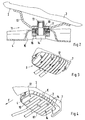
- a shield or a plate-shaped shield or shell 4 is detachably or permanently attached via connecting means 11 on one of the lane 1 trimmed bottom surface 2 of a muffler 3 not shown in detail.
- the shell 4 or the plate or the plate is in particular spaced from the lower surface 2 at an acute angle ⁇ arranged and thereby employed such that in extension of the shell 4 at about the same level, a lower surface 6 of the vehicle rear 7 connects with a gap.
- the shell 4 may extend approximately over the entire lower surface 2, wherein also beyond cover or larger shell 4 would be possible according to the invention, if required by the conditions of a more optimal air flow guide with a maximum output value ,
- the shell 4 has edges K, K1 which are trimmed towards the inside of the lower surface 2 of the silencer 3.
- the edge K1 is angled inwardly so far that the free edge end 8 extends over a tangential plane XX of the lower surface 2 of the muffler 3, so that an air flow is deflected down towards the lane 1 and turbulence between the lower surface 2 of the muffler 3 and the shell 4 can be largely avoided.
- the screws 14 between the screw head and the shell 4 may have a spacer 16 and a spring washer 17, which are arranged on a sleeve 18 to compensate for component tolerances.
- the fastening screw can be designed so that a variable adjustment at a certain angle to the lower surface 2 of the muffler 3 is possible.
- the connecting elements can be designed so that they take over the function of an acoustic, mechanical and thermal decoupling.
- Fig. 5 may be arranged in a sleeve 20 having a retaining ring 21, in which the shell 4 of the spoiler is held.
- the shell 4 may be provided for stiffening the shell surface with longitudinal beads 19 or corresponding impressions. Furthermore, in the case of a shell 4 made of plastic, it may have a heat protection 22 made of aluminum or the like, which may be provided with a protruding rib 26.
Landscapes
- Engineering & Computer Science (AREA)
- Chemical & Material Sciences (AREA)
- Combustion & Propulsion (AREA)
- Transportation (AREA)
- Mechanical Engineering (AREA)
- Cooling, Air Intake And Gas Exhaust, And Fuel Tank Arrangements In Propulsion Units (AREA)
- Exhaust Silencers (AREA)
- Motor Or Generator Cooling System (AREA)
- Motor Or Generator Frames (AREA)
- Air-Conditioning For Vehicles (AREA)
Claims (11)
- Dispositif aérodynamique de véhicule automobile, qui est disposé sur le dessous de caisse du véhicule, caractérisé en ce que le dispositif aérodynamique est constitué d'une coque (4) en forme de plaque qui, afin de diriger l'écoulement de l'air, via des éléments de liaison (11 ; 11a) amovibles ou inamovibles, est fixée sous un angle aigu (α) à une face inférieure (2), tournée vers la chaussée (1), d'un silencieux (3) d'un système d'échappement qui est disposé sur la partie arrière (7) du véhicule.
- Dispositif aérodynamique selon la revendication 1, caractérisé en ce que la coque (4) est inclinée sous l'angle aigu (α) à distance de la face inférieure (2) du silencieux (3) de telle sorte qu'une face inférieure (6) de la partie arrière (7) du véhicule s'étend dans le prolongement de la face de la coque (4), environ au même niveau.
- Dispositif aérodynamique selon la revendication 1 ou 2, caractérisé en ce que la coque (4) s'étend quasiment sur toute la face inférieure (2) du silencieux (3) qui est tournée vers la chaussée (1).
- Dispositif aérodynamique selon l'une quelconque des revendications 1, 2 ou 3, caractérisé en ce que la coque (4) présente des arêtes (K, K1) rabattues vers l'intérieur, dirigées vers la face inférieure (2) du silencieux (3).
- Dispositif aérodynamique selon l'une quelconque des revendications précédentes, caractérisé en ce que l'arête rabattue (K1) de la coque (4) qui se trouve à l'avant - par rapport à la direction de marche F du véhicule - est recourbée vers l'intérieur en direction du silencieux (3) de telle sorte que l'extrémité libre (8) de l'arête est disposée au-dessus d'un plan (X-X) tangentiel à la face inférieure (2) du silencieux (3).
- Dispositif aérodynamique selon l'une quelconque des revendications précédentes, caractérisé en ce que des étriers en tôle (12) sont fixés sur la face inférieure (2) du silencieux (3) comme éléments de liaison (11 ; 11a), et présentent des écrous (13) pouvant être bloqués qui reçoivent et maintiennent des vis de fixation (14) destinées à fixer en position la coque (4).
- Dispositif aérodynamique selon la revendication 6, caractérisé en ce que les têtes des vis de fixation (14) sont disposées dans des renfoncements (15) de la coque (4).
- Dispositif aérodynamique selon l'une quelconque des revendications précédentes, caractérisé en ce que la coque (4) présente des régions repoussées (19) ou des moulures parallèles s'étendant dans la direction longitudinale du véhicule.
- Dispositif aérodynamique selon la revendication 1, caractérisé en ce que la coque (4) constituant le dispositif aérodynamique est disposée sur une face inférieure (2) d'une coque d'un silencieux final (3) afin de diriger l'écoulement de l'air sur le dessous de caisse (6) du véhicule, ledit dispositif étant incliné sous l'angle (α) vers la chaussée (1) et présentant une face de guidage d'air (coque 4) s'étendant sur toute la largeur et sur toute la longueur de la coque du silencieux (3), face qui s'étend au même niveau qu'une face inférieure (6) d'une partie arrière (7) de carrosserie.
- Dispositif aérodynamique selon l'une quelconque des revendications précédentes, caractérisé en ce que les éléments de liaison (11 ; 11a) sont réalisés de telle sorte qu'ils assurent une fonction de désaccouplement acoustique, thermique et mécanique.
- Dispositif aérodynamique selon l'une quelconque des revendications précédentes, caractérisé en ce que l'élément de liaison (11a) est constitué d'une vis de fixation (14) disposée dans un manchon (20), et le manchon (20) reçoit extérieurement une bague de support (21) qui porte la coque (4) dans une rainure circonférentielle (25).
Applications Claiming Priority (2)
| Application Number | Priority Date | Filing Date | Title |
|---|---|---|---|
| DE102004030211 | 2004-06-22 | ||
| DE102004030211A DE102004030211B3 (de) | 2004-06-22 | 2004-06-22 | Luftleitelement für ein Kraftfahrzeug |
Publications (3)
| Publication Number | Publication Date |
|---|---|
| EP1609706A2 EP1609706A2 (fr) | 2005-12-28 |
| EP1609706A3 EP1609706A3 (fr) | 2006-05-03 |
| EP1609706B1 true EP1609706B1 (fr) | 2008-01-02 |
Family
ID=34935081
Family Applications (1)
| Application Number | Title | Priority Date | Filing Date |
|---|---|---|---|
| EP05008030A Expired - Fee Related EP1609706B1 (fr) | 2004-06-22 | 2005-04-13 | Dispositif aérodynamique de véhicule automobile |
Country Status (3)
| Country | Link |
|---|---|
| EP (1) | EP1609706B1 (fr) |
| AT (1) | ATE382535T1 (fr) |
| DE (2) | DE102004030211B3 (fr) |
Families Citing this family (4)
| Publication number | Priority date | Publication date | Assignee | Title |
|---|---|---|---|---|
| WO2007096553A2 (fr) * | 2006-02-27 | 2007-08-30 | Renault S.A.S | Structure arriere d'un vehicule automobile |
| DE102012205582A1 (de) * | 2012-04-04 | 2013-10-10 | Bayerische Motoren Werke Aktiengesellschaft | Kraftfahrzeug mit einer Unterbodenverkleidung |
| DE102020103196A1 (de) | 2020-02-07 | 2021-08-12 | Bayerische Motoren Werke Aktiengesellschaft | Kraftfahrzeug mit einer im Heckbereich vorgesehenen Unterbodenverkleidung |
| DE102021100269B4 (de) | 2021-01-11 | 2023-01-19 | Dr. Ing. H.C. F. Porsche Aktiengesellschaft | Schalldämpfer einer Abgasanlage eines Verbrennungsmotors |
Family Cites Families (4)
| Publication number | Priority date | Publication date | Assignee | Title |
|---|---|---|---|---|
| GB8506708D0 (en) * | 1985-03-15 | 1985-04-17 | Kirkwood T | Wheel spray suppressors |
| DE3525036A1 (de) * | 1985-07-13 | 1987-01-15 | Audi Ag | Vorrichtung zum abdecken eines vertieften bereiches des unterbodens eines kraftfahrzeuges |
| DE3625814A1 (de) * | 1986-07-30 | 1988-02-18 | Bayerische Motoren Werke Ag | Kraftfahrzeug, insbesondere personenkraftwagen |
| DE20314128U1 (de) * | 2003-09-08 | 2003-12-18 | Ford Global Technologies, LLC, Dearborn | Diffusor für Kraftfahrzeuge |
-
2004
- 2004-06-22 DE DE102004030211A patent/DE102004030211B3/de not_active Expired - Fee Related
-
2005
- 2005-04-13 EP EP05008030A patent/EP1609706B1/fr not_active Expired - Fee Related
- 2005-04-13 DE DE502005002374T patent/DE502005002374D1/de active Active
- 2005-04-13 AT AT05008030T patent/ATE382535T1/de not_active IP Right Cessation
Also Published As
| Publication number | Publication date |
|---|---|
| EP1609706A2 (fr) | 2005-12-28 |
| EP1609706A3 (fr) | 2006-05-03 |
| DE502005002374D1 (de) | 2008-02-14 |
| ATE382535T1 (de) | 2008-01-15 |
| DE102004030211B3 (de) | 2005-11-17 |
Similar Documents
| Publication | Publication Date | Title |
|---|---|---|
| EP0711700B1 (fr) | Déflecteur comportant des prises d'air moteur | |
| DE102010036442B4 (de) | Luftleitvorrichtung | |
| EP0258538A2 (fr) | Dispositif d'amenée de l'air de refroidissement à un disque de frein | |
| DE102007033116A1 (de) | Frontendmodul für Fahrzeuge | |
| EP1559641A2 (fr) | Véhicule automobile avec un dispositif de guidage d'air | |
| EP1609706B1 (fr) | Dispositif aérodynamique de véhicule automobile | |
| DE102005039469A1 (de) | Frontendmodul mit einem Montageträger mit unterem Querträger | |
| DE102017109887B4 (de) | Fahrzeugheck eines Kraftfahrzeuges | |
| DE2851639A1 (de) | Vorrichtung zur leitung der windstroemung an fahrzeugen | |
| EP1398198B1 (fr) | Véhicule automobile avec au moins un radiateur | |
| EP0848144B1 (fr) | Tuyau de sortie pour le conduit d'échappement d'un pôt d'échappement d'un véhicule à moteur | |
| DE102008024786A1 (de) | Aerodynamisches Verkleidungsteil | |
| DE102008024896B4 (de) | Luftleiteinrichtung | |
| DE102014205603A1 (de) | Luftleitvorrichtung für ein Fahrzeug | |
| DE102006044952A1 (de) | Vorrichtung zur Luftkühlung einer Radbremse an einem Kraftfahrzeug | |
| DE102007042611A1 (de) | Frontgrill | |
| DE102009005942A1 (de) | Befestigungsanordnung für eine Wischeranlage | |
| DE102013106036A1 (de) | Bugverkleidungsteil für ein Kraftfahrzeug mit seitlichen Lufteinlässen | |
| DE102011051500A1 (de) | Fahrzeugaufbau-Versteifungsvorrichtung | |
| DE102016105082A1 (de) | Luftleiteinrichtung | |
| DE102010017373A1 (de) | Kraftfahrzeug | |
| DE102007054854A1 (de) | Einrichtung zur Kühlung eines Bauteiles an einem Kraftfahrzeug | |
| DE102004043544B4 (de) | Spoiler | |
| DE102018103076A1 (de) | Luftleiteinrichtung für ein Kraftfahrzeug | |
| DE102015005013A1 (de) | Luftleiteinrichtung für einen Fahrwerkslenker |
Legal Events
| Date | Code | Title | Description |
|---|---|---|---|
| PUAI | Public reference made under article 153(3) epc to a published international application that has entered the european phase |
Free format text: ORIGINAL CODE: 0009012 |
|
| AK | Designated contracting states |
Kind code of ref document: A2 Designated state(s): AT BE BG CH CY CZ DE DK EE ES FI FR GB GR HU IE IS IT LI LT LU MC NL PL PT RO SE SI SK TR |
|
| AX | Request for extension of the european patent |
Extension state: AL BA HR LV MK YU |
|
| PUAL | Search report despatched |
Free format text: ORIGINAL CODE: 0009013 |
|
| AK | Designated contracting states |
Kind code of ref document: A3 Designated state(s): AT BE BG CH CY CZ DE DK EE ES FI FR GB GR HU IE IS IT LI LT LU MC NL PL PT RO SE SI SK TR |
|
| AX | Request for extension of the european patent |
Extension state: AL BA HR LV MK YU |
|
| 17P | Request for examination filed |
Effective date: 20061103 |
|
| AKX | Designation fees paid |
Designated state(s): AT DE ES FR GB SE |
|
| GRAP | Despatch of communication of intention to grant a patent |
Free format text: ORIGINAL CODE: EPIDOSNIGR1 |
|
| GRAS | Grant fee paid |
Free format text: ORIGINAL CODE: EPIDOSNIGR3 |
|
| GRAA | (expected) grant |
Free format text: ORIGINAL CODE: 0009210 |
|
| AK | Designated contracting states |
Kind code of ref document: B1 Designated state(s): AT DE ES FR GB SE |
|
| REG | Reference to a national code |
Ref country code: GB Ref legal event code: FG4D Free format text: NOT ENGLISH |
|
| REF | Corresponds to: |
Ref document number: 502005002374 Country of ref document: DE Date of ref document: 20080214 Kind code of ref document: P |
|
| GBT | Gb: translation of ep patent filed (gb section 77(6)(a)/1977) |
Effective date: 20080407 |
|
| RAP2 | Party data changed (patent owner data changed or rights of a patent transferred) |
Owner name: DR. ING. H.C. F. PORSCHE AKTIENGESELLSCHAFT |
|
| RAP2 | Party data changed (patent owner data changed or rights of a patent transferred) |
Owner name: DR. ING. H.C. F. PORSCHE AKTIENGESELLSCHAFT |
|
| ET | Fr: translation filed | ||
| PG25 | Lapsed in a contracting state [announced via postgrant information from national office to epo] |
Ref country code: ES Free format text: LAPSE BECAUSE OF FAILURE TO SUBMIT A TRANSLATION OF THE DESCRIPTION OR TO PAY THE FEE WITHIN THE PRESCRIBED TIME-LIMIT Effective date: 20080413 |
|
| PG25 | Lapsed in a contracting state [announced via postgrant information from national office to epo] |
Ref country code: SE Free format text: LAPSE BECAUSE OF FAILURE TO SUBMIT A TRANSLATION OF THE DESCRIPTION OR TO PAY THE FEE WITHIN THE PRESCRIBED TIME-LIMIT Effective date: 20080402 |
|
| PLBE | No opposition filed within time limit |
Free format text: ORIGINAL CODE: 0009261 |
|
| STAA | Information on the status of an ep patent application or granted ep patent |
Free format text: STATUS: NO OPPOSITION FILED WITHIN TIME LIMIT |
|
| 26N | No opposition filed |
Effective date: 20081003 |
|
| REG | Reference to a national code |
Ref country code: FR Ref legal event code: TP |
|
| PG25 | Lapsed in a contracting state [announced via postgrant information from national office to epo] |
Ref country code: AT Free format text: LAPSE BECAUSE OF NON-PAYMENT OF DUE FEES Effective date: 20080413 |
|
| REG | Reference to a national code |
Ref country code: FR Ref legal event code: CD |
|
| REG | Reference to a national code |
Ref country code: FR Ref legal event code: TP |
|
| REG | Reference to a national code |
Ref country code: GB Ref legal event code: 732E Free format text: REGISTERED BETWEEN 20110310 AND 20110316 |
|
| REG | Reference to a national code |
Ref country code: GB Ref legal event code: 732E Free format text: REGISTERED BETWEEN 20110331 AND 20110406 |
|
| REG | Reference to a national code |
Ref country code: FR Ref legal event code: PLFP Year of fee payment: 12 |
|
| REG | Reference to a national code |
Ref country code: FR Ref legal event code: PLFP Year of fee payment: 13 |
|
| REG | Reference to a national code |
Ref country code: FR Ref legal event code: PLFP Year of fee payment: 14 |
|
| PGFP | Annual fee paid to national office [announced via postgrant information from national office to epo] |
Ref country code: DE Payment date: 20180426 Year of fee payment: 14 |
|
| PGFP | Annual fee paid to national office [announced via postgrant information from national office to epo] |
Ref country code: FR Payment date: 20180420 Year of fee payment: 14 |
|
| PGFP | Annual fee paid to national office [announced via postgrant information from national office to epo] |
Ref country code: GB Payment date: 20180418 Year of fee payment: 14 |
|
| REG | Reference to a national code |
Ref country code: DE Ref legal event code: R119 Ref document number: 502005002374 Country of ref document: DE |
|
| GBPC | Gb: european patent ceased through non-payment of renewal fee |
Effective date: 20190413 |
|
| PG25 | Lapsed in a contracting state [announced via postgrant information from national office to epo] |
Ref country code: DE Free format text: LAPSE BECAUSE OF NON-PAYMENT OF DUE FEES Effective date: 20191101 Ref country code: GB Free format text: LAPSE BECAUSE OF NON-PAYMENT OF DUE FEES Effective date: 20190413 |
|
| PG25 | Lapsed in a contracting state [announced via postgrant information from national office to epo] |
Ref country code: FR Free format text: LAPSE BECAUSE OF NON-PAYMENT OF DUE FEES Effective date: 20190430 |