EP1609706B1 - Streamlining device for a motor vehicle - Google Patents
Streamlining device for a motor vehicle Download PDFInfo
- Publication number
- EP1609706B1 EP1609706B1 EP05008030A EP05008030A EP1609706B1 EP 1609706 B1 EP1609706 B1 EP 1609706B1 EP 05008030 A EP05008030 A EP 05008030A EP 05008030 A EP05008030 A EP 05008030A EP 1609706 B1 EP1609706 B1 EP 1609706B1
- Authority
- EP
- European Patent Office
- Prior art keywords
- shell
- air guiding
- guiding element
- silencer
- undersurface
- Prior art date
- Legal status (The legal status is an assumption and is not a legal conclusion. Google has not performed a legal analysis and makes no representation as to the accuracy of the status listed.)
- Expired - Fee Related
Links
Images


Classifications
-
- B—PERFORMING OPERATIONS; TRANSPORTING
- B62—LAND VEHICLES FOR TRAVELLING OTHERWISE THAN ON RAILS
- B62D—MOTOR VEHICLES; TRAILERS
- B62D35/00—Vehicle bodies characterised by streamlining
- B62D35/02—Streamlining the undersurfaces
-
- Y—GENERAL TAGGING OF NEW TECHNOLOGICAL DEVELOPMENTS; GENERAL TAGGING OF CROSS-SECTIONAL TECHNOLOGIES SPANNING OVER SEVERAL SECTIONS OF THE IPC; TECHNICAL SUBJECTS COVERED BY FORMER USPC CROSS-REFERENCE ART COLLECTIONS [XRACs] AND DIGESTS
- Y02—TECHNOLOGIES OR APPLICATIONS FOR MITIGATION OR ADAPTATION AGAINST CLIMATE CHANGE
- Y02T—CLIMATE CHANGE MITIGATION TECHNOLOGIES RELATED TO TRANSPORTATION
- Y02T10/00—Road transport of goods or passengers
- Y02T10/80—Technologies aiming to reduce greenhouse gasses emissions common to all road transportation technologies
- Y02T10/82—Elements for improving aerodynamics
-
- Y—GENERAL TAGGING OF NEW TECHNOLOGICAL DEVELOPMENTS; GENERAL TAGGING OF CROSS-SECTIONAL TECHNOLOGIES SPANNING OVER SEVERAL SECTIONS OF THE IPC; TECHNICAL SUBJECTS COVERED BY FORMER USPC CROSS-REFERENCE ART COLLECTIONS [XRACs] AND DIGESTS
- Y02—TECHNOLOGIES OR APPLICATIONS FOR MITIGATION OR ADAPTATION AGAINST CLIMATE CHANGE
- Y02T—CLIMATE CHANGE MITIGATION TECHNOLOGIES RELATED TO TRANSPORTATION
- Y02T10/00—Road transport of goods or passengers
- Y02T10/80—Technologies aiming to reduce greenhouse gasses emissions common to all road transportation technologies
- Y02T10/88—Optimized components or subsystems, e.g. lighting, actively controlled glasses
Definitions
- the invention relates to an air guide element for a motor vehicle, which is arranged on the underbody of the vehicle.
- a spoiler is known on the bottom side at the rear of a motor vehicle, which is arranged at a distance from the vehicle body and is surrounded by air. Furthermore, the spoiler can also be formed by a lower surface of the muffler of an exhaust system and is designed in one piece with this and is dependent on the position of the muffler.
- the object of the invention is to provide an air guide for a motor vehicle, which is to be arranged independently of vehicle elements and mounted in a simple manner.
- the air guide can be variably mounted in its employment on the muffler and thus can be aligned to a Heckab gleichteil, so that a continuous air flow guide can be done without interruption.
- the spoiler element consists of a plate-shaped shell, which is held on a road surface of the underside of a arranged at the rear of the vehicle muffler exhaust system for air flow at an acute angle via detachable or non-detachable fasteners.
- the shell is spaced apart from the lower surface of the muffler with the acute angle employed such that extends in extension of the surface of the shell at about the same level as a lower surface of the rear of the vehicle.
- an air duct is achieved independently of the position of the muffler, wherein the shell can extend almost over the entire trimmed the underside of the surface of the muffler.
- the shell can extend almost over the entire trimmed the underside of the surface of the muffler.
- the - in relation to the direction of travel F of the vehicle - forward folded edge of the shell is angled inwardly towards the muffler such that the free edge end extends over a tangential plane of the lower surface of the muffler or this edge end above the Tangential plane is located.
- a simple mounting of the shell on the lower surface of the muffler via so-called fasteners the e.g. are designed as sheet metal brackets, which are attached to the lower surface of the muffler, and which, for example, Annietmuttern, sheet metal nuts, weld nuts, holding the mounting screws holding down the shell record.
- the heads of the fastening screws are arranged in depressions of the shell, so that an air-resistance-free air flow can take place in these regions.
- the sheet metal brackets can also be designed according to the invention so that the shell is variably adjustable via screws on the brackets.
- a shield or a plate-shaped shield or shell 4 is detachably or permanently attached via connecting means 11 on one of the lane 1 trimmed bottom surface 2 of a muffler 3 not shown in detail.
- the shell 4 or the plate or the plate is in particular spaced from the lower surface 2 at an acute angle ⁇ arranged and thereby employed such that in extension of the shell 4 at about the same level, a lower surface 6 of the vehicle rear 7 connects with a gap.
- the shell 4 may extend approximately over the entire lower surface 2, wherein also beyond cover or larger shell 4 would be possible according to the invention, if required by the conditions of a more optimal air flow guide with a maximum output value ,
- the shell 4 has edges K, K1 which are trimmed towards the inside of the lower surface 2 of the silencer 3.
- the edge K1 is angled inwardly so far that the free edge end 8 extends over a tangential plane XX of the lower surface 2 of the muffler 3, so that an air flow is deflected down towards the lane 1 and turbulence between the lower surface 2 of the muffler 3 and the shell 4 can be largely avoided.
- the screws 14 between the screw head and the shell 4 may have a spacer 16 and a spring washer 17, which are arranged on a sleeve 18 to compensate for component tolerances.
- the fastening screw can be designed so that a variable adjustment at a certain angle to the lower surface 2 of the muffler 3 is possible.
- the connecting elements can be designed so that they take over the function of an acoustic, mechanical and thermal decoupling.
- Fig. 5 may be arranged in a sleeve 20 having a retaining ring 21, in which the shell 4 of the spoiler is held.
- the shell 4 may be provided for stiffening the shell surface with longitudinal beads 19 or corresponding impressions. Furthermore, in the case of a shell 4 made of plastic, it may have a heat protection 22 made of aluminum or the like, which may be provided with a protruding rib 26.
Abstract
Description
Die Erfindung bezieht sich auf ein Luftleitelement für ein Kraftfahrzeug, das am Unterboden des Fahrzeugs angeordnet ist.The invention relates to an air guide element for a motor vehicle, which is arranged on the underbody of the vehicle.
Aus der
Aufgabe der Erfindung ist es, ein Luftleitelement für ein Kraftfahrzeug zu schaffen, das unabhängig von Fahrzeugelementen anzuordnen und in einfacher Weise montierbar ist.The object of the invention is to provide an air guide for a motor vehicle, which is to be arranged independently of vehicle elements and mounted in a simple manner.
Diese Aufgabe wird erfindungsgemäß durch die Merkmale des Anspruchs 1 gelöst. Weitere vorteilhafte Merkmale beinhalten die Unteransprüche.This object is achieved by the features of claim 1. Further advantageous features include the subclaims.
Die mit der Erfindung hauptsächlich erzielten Vorteile bestehen darin, dass das Luftleitelement in seiner Anstellung variabel am Schalldämpfer angebracht werden kann und somit auch zu einem Heckabschlussteil ausrichtbar ist, damit eine kontinuierliche Luftströmungsführung ohne Unterbrechung erfolgen kann. Hierzu ist das Luftleitelement aus einer plattenförmigen Schale bestehend, die an einer der Fahrbahn zugerichteten Unterfläche eines am Heck des Fahrzeugs angeordneten Schalldämpfers einer Abgasanlage zur Luftströmungsführung unter einem spitzen Winkel über lösbare oder unlösbare Verbindungselemente gehalten ist. Insbesondere ist die Schale beabstandet zur Unterfläche des Schalldämpfers mit dem spitzen Winkel derart angestellt, dass in Verlängerung der Fläche der Schale etwa niveaugleich eine Unterfläche des Fahrzeughecks verläuft.The advantages achieved by the invention are that the air guide can be variably mounted in its employment on the muffler and thus can be aligned to a Heckabschlussteil, so that a continuous air flow guide can be done without interruption. For this purpose, the spoiler element consists of a plate-shaped shell, which is held on a road surface of the underside of a arranged at the rear of the vehicle muffler exhaust system for air flow at an acute angle via detachable or non-detachable fasteners. In particular, the shell is spaced apart from the lower surface of the muffler with the acute angle employed such that extends in extension of the surface of the shell at about the same level as a lower surface of the rear of the vehicle.
Hierdurch wird in vorteilhafter Weise nach der Erfindung erreicht, dass eine Luftführung unabhängig von der Lage des Schalldämpfers erzielt wird, wobei die Schale sich nahezu über die gesamte der Fahrbahn zugerichtete Unterfläche des Schalldämpfers erstrecken kann. Zudem wird erreicht, dass sich eine relativ große Fläche zur gezielten Luftführung ergibt und Verwirbelungen weitestgehend vermieden werden und sich zwischen der Fahrbahn und dem Luftführungselement ein Unterdruck einstellt, welcher eine heckseitige Abtriebskraft bewirkt. Hierzu dient auch, dass die Schale nach innen der Unterfläche des Schalldämpfers zugerichtete umgestellte Kanten aufweist. Insbesondere ist vorgesehen, dass die - in Bezug auf die Fahrtrichtung F des Fahrzeug - vornliegende umgestellte Kante der Schale nach innen zum Schalldämpfer hin derart abgewinkelt ist, dass das freie Kantenende sich über eine Tangentialebene der Unterfläche des Schalldämpfers erstreckt bzw. sich dieses Kantenende oberhalb der Tangentialebene befindet. Durch diese Maßnahme wird eine gezielte Luftführung erreicht, indem es vermieden wird, dass Luftströme zwischen die Unterfläche des Schalldämpfers und der Schale gelangen können und sich störende Verwirbelungen bilden.As a result, it is achieved in an advantageous manner according to the invention that an air duct is achieved independently of the position of the muffler, wherein the shell can extend almost over the entire trimmed the underside of the surface of the muffler. In addition, it is achieved that there is a relatively large area for targeted air flow and turbulence is largely avoided and adjusts a negative pressure between the road and the air guide element, which causes a rear-side output force. This also serves that the shell has inwardly the underside of the muffler trimmed converted edges. In particular, it is provided that the - in relation to the direction of travel F of the vehicle - forward folded edge of the shell is angled inwardly towards the muffler such that the free edge end extends over a tangential plane of the lower surface of the muffler or this edge end above the Tangential plane is located. By this measure, a targeted air flow is achieved by it is avoided that air currents can get between the bottom surface of the muffler and the shell and form disturbing turbulence.
Eine einfache Montage der Schale an der Unterfläche des Schalldämpfers erfolgt über sogenannte Verbindungselemente, die z.B. als Blechbügel ausgeführt sind, welche an der Unterfläche des Schalldämpfers befestigt werden, und welche beispielsweise Annietmuttern, Blechmuttern, Schweißmuttern aufweisen, die Befestigungsschrauben zur Festlegung der Schale haltend aufnehmen. Insbesondere sind die Köpfe der Befestigungsschrauben in Vertiefungen der Schale angeordnet, damit eine in diesen Bereichen luftwiderstandsfreie Luftströmung erfolgen kann. Die Blechbügel können nach der Erfindung auch so gestaltet sein, dass die Schale über Stellschrauben an den Bügeln variabel einstellbar ist.A simple mounting of the shell on the lower surface of the muffler via so-called fasteners, the e.g. are designed as sheet metal brackets, which are attached to the lower surface of the muffler, and which, for example, Annietmuttern, sheet metal nuts, weld nuts, holding the mounting screws holding down the shell record. In particular, the heads of the fastening screws are arranged in depressions of the shell, so that an air-resistance-free air flow can take place in these regions. The sheet metal brackets can also be designed according to the invention so that the shell is variably adjustable via screws on the brackets.
Weitere Einzelheiten der Erfindung sind in den Unteransprüchen gekennzeichnet, wobei es sich in der Praxis als optimal erwiesen hat, wenn an der Unterfläche einer Schale eines Endschalldämpfers die als Luftleitelement ausgebildete Schale zur Luftströmungsführung am Fahrzeugunterboden angeordnet ist, das zur Fahrbahn unter einem Winkel angestellt wird und eine über die gesamte Breite und Länge der Schale des Schalldämpfers sich erstreckende Luftleitfläche aufweist, die niveaugleich mit einer Unterfläche eines heckseitigen Karosserieteils verläuft.Further details of the invention are characterized in the subclaims, wherein it has proven in practice to be optimal when arranged on the lower surface of a shell of a rear muffler designed as an air guide shell for air flow guide on the vehicle underbody, which hired to the roadway at an angle and has an over the entire width and length of the shell of the muffler extending air guide surface which is at the same level as a lower surface of a rear-side body part.
Ein Ausführungsbeispiel der Erfindung ist in den Zeichnungen dargestellt und wird im folgenden näher beschrieben.An embodiment of the invention is illustrated in the drawings and will be described in more detail below.
Es zeigen
- Fig. 1
- eine schematische Darstellung eines heckseitigen Schalldämpfers eines Fahrzeugs mit aufgesetztem Luftleitelement von der Seite her gesehen,
- Fig. 2
- eine Schnittdarstellung durch ein Verbindungselement für das Luftleitelement am Schalldämpfer,
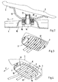
- Fig. 3
- eine schaubildliche Darstellung auf einen Schalldämpfer ohne Luftleitelement von unten her gesehen mit Verbindungselementen, und
- Fig. 4
- eine schaubildliche Darstellung gemäß Fig. 3 auf den Schalldämpfer mit befestigtem Luftleitelement und
- Fig. 5
- eine weitere Ausführung eines Verbindungselements.
- Fig. 1
- a schematic representation of a rear-side muffler of a vehicle with attached air guide seen from the side,
- Fig. 2
- a sectional view through a connecting element for the air guide on the muffler,
- Fig. 3
- a perspective view of a muffler without air deflector seen from below with fasteners, and
- Fig. 4
- a perspective view of FIG. 3 on the muffler with attached air guide and
- Fig. 5
- a further embodiment of a connecting element.
Wie in Fig. 1 näher dargestellt, ist an einer der Fahrbahn 1 zugerichteten Unterfläche 2 eines Schalldämpfers 3 einer nicht näher gezeigten Abgasanlage ein Schild bzw. ein plattenförmiges Schild oder Schale 4 über Verbindungsmittel 11 lösbar oder unlösbar befestigt.As shown in more detail in Fig. 1, a shield or a plate-shaped shield or
Die Schale 4 oder das Schild bzw. die Platte ist insbesondere beabstandet zur Unterfläche 2 unter einem spitzen Winkel α angeordnet und hierdurch derart angestellt, dass in Verlängerung der Schale 4 etwa niveaugleich sich eine Unterfläche 6 des Fahrzeughecks 7 mit einem Zwischenraum anschließt.The
Wie in Fig. 4 gezeigt, kann sich die Schale 4 in etwa über die gesamte Unterfläche 2 erstrecken, wobei auch eine darüber hinausgehende Abdeckung bzw. größere Schale 4 nach der Erfindung möglich wäre, wenn dies die Gegebenheiten einer optimaleren Luftströmungsführung mit einem maximalen Abtriebswert erfordern.As shown in Fig. 4, the
Die Schale 4 weist nach innen der Unterfläche 2 des Schalldämpfers 3 zugerichtete Kanten K, K1 auf. Die Kante K1 ist so weit nach innen abgewinkelt, dass das freie Kantenende 8 sich über eine Tangentialebene X-X der Unterfläche 2 des Schalldämpfers 3 erstreckt, so dass eine Luftströmung nach unten in Richtung Fahrbahn 1 abgelenkt wird und Verwirbelungen zwischen der Unterfläche 2 des Schalldämpfers 3 und der Schale 4 weitestgehend vermieden werden können.The
Eine Befestigung der Schale 4 an der Unterfläche 2 des Schalldämpfers 3 erfolgt mittels Verbindungselementen 11, die aus Blechbügeln 12 bestehen und innenseitig beispielsweise Annietmuttern 13 aufweisen, in welche Befestigungsschrauben 14 einsetzbar sind.An attachment of the
Zur Vermeidung von unnötigen Luftwiderständen durch vorragende Schraubenköpfe an der Schale sind diese in Vertiefungen 15 der Schale 4 eingelassen. Zur Befestigung der Schale 4 an der Unterfläche 2 des Schalldämpfers 3 können die Schrauben 14 zwischen dem Schraubenkopf und der Schale 4 eine Distanzscheibe 16 und eine Federscheibe 17 aufweisen, die auf einer Hülse 18 angeordnet sind, um Bauteiltoleranzen auszugleichen. Des Weiteren kann die Befestigungsschraube so ausgeführt sein, dass eine variable Einstellung unter einem bestimmten Winkel zur Unterfläche 2 des Schalldämpfers 3 möglich wird. Weiterhin können die Verbindungselemente so gestaltet sein, dass sie die Funktion einer akustischen, mechanischen und thermischen Entkopplung übernehmen.To avoid unnecessary air resistance by protruding screw heads on the shell these are recessed in
Die Befestigungsschraube 14 des Verbindungselements 11a kann nach einer weiteren Ausführung gem. Fig. 5 in einer Hülse 20 angeordnet sein, die einen Haltering 21 aufweist, in welchem die Schale 4 des Luftleitelements gehalten wird.The
Die Schale 4 kann zur Versteifung der Schalenfläche mit längsverlaufenden Sicken 19 oder entsprechenden Einprägungen versehen sein. Des Weiteren kann die bei einer aus Kunststoff bestehenden Schale 4, diese einen Hitzeschutz 22 aus Aluminium oder dgl. aufweisen, das mit einer hachstehenden Rippe 26 versehen sein kann.The
Claims (11)
- Air guiding element for a motor vehicle, which air guiding element is arranged on the underbody of the vehicle, characterized in that the air guiding element is composed of a plate-shaped shell (4) which, for airflow guidance, is held at an acute angle (α) by means of detachable or non-detachable connecting elements (11; 11a) on an undersurface (2), which is aligned towards the road surface (1), of a silencer (3), which is arranged at the rear (7) of the vehicle, of an exhaust system.
- Air guiding element according to Claim 1, characterized in that the shell (4) is arranged spaced apart from the undersurface (2) of the silencer (3) at the acute angle (α) such that an undersurface (6) of the vehicle rear (7) runs as an elongation of the surface of the shell (4) at approximately the same level.
- Air guiding element according to Claims 1 or 2, characterized in that the shell (4) extends almost over the entire undersurface (2), which is aligned towards the road surface (1), of the silencer (3).
- Air guiding element according to Claims 1, 2 or 3, characterized in that the shell (4) has upturned edges (K, K1) which are aligned inward towards the undersurface (2) of the silencer (3).
- Air guiding element according to one of the preceding claims, characterized in that the forward upturned edge (K1) - in relation to the direction of travel F of the vehicle - of the shell (4) is angled inward towards the silencer (3) in such a way that the free edge end (8) is arranged above a tangential plane (X-X) of the undersurface (2) of the silencer (3).
- Air guiding element according to one of the preceding claims, characterized in that sheet metal brackets (12) are fastened as connecting elements (11; 11a) to the undersurface (2) of the silencer (3), which sheet metal brackets (12) have fixable nuts (13) which hold fastening screws (14) in a retentive fashion in order to fix the shell (4).
- Air guiding element according to Claim 6, characterized in that the heads of the fastening screws (14) are arranged in depressions (15) of the shell (4).
- Air guiding element according to one of the preceding claims, characterized in that the shell (4) has embossings (19) or beads which run parallel in the vehicle longitudinal direction.
- Air guiding element according to Claim 1, characterized in that the shell (4), which forms the air guiding element, for airflow guidance at the vehicle underbody (6) is arranged on an undersurface (2) of a shell of a final silencer (3), which air guiding element is arranged at the angle (α) to the road surface (1) and has an air guiding surface (shell 4) which extends over the entire width and length of the shell of the silencer (3), which air guiding surface (4) runs at the same level as an undersurface (6) of a rear-side body part (7).
- Air guiding element according to one of the preceding claims, characterized in that the connecting elements (11; 11a) are designed such that the function of acoustic, thermal and mechanical decoupling can be assumed.
- Air guiding element according to one of the preceding claims, characterized in that the connecting element (11a) is composed of a fastening screw (14) which is arranged in a sleeve (20), and the sleeve (20) holds, at the outside, a retaining ring (21) which supports the shell (4) in a peripheral groove (25).
Applications Claiming Priority (2)
| Application Number | Priority Date | Filing Date | Title |
|---|---|---|---|
| DE102004030211A DE102004030211B3 (en) | 2004-06-22 | 2004-06-22 | Air guide element for vehicle consists of bowl creating the outflow over undersurface of the silencer at rear of vehicle |
| DE102004030211 | 2004-06-22 |
Publications (3)
| Publication Number | Publication Date |
|---|---|
| EP1609706A2 EP1609706A2 (en) | 2005-12-28 |
| EP1609706A3 EP1609706A3 (en) | 2006-05-03 |
| EP1609706B1 true EP1609706B1 (en) | 2008-01-02 |
Family
ID=34935081
Family Applications (1)
| Application Number | Title | Priority Date | Filing Date |
|---|---|---|---|
| EP05008030A Expired - Fee Related EP1609706B1 (en) | 2004-06-22 | 2005-04-13 | Streamlining device for a motor vehicle |
Country Status (3)
| Country | Link |
|---|---|
| EP (1) | EP1609706B1 (en) |
| AT (1) | ATE382535T1 (en) |
| DE (2) | DE102004030211B3 (en) |
Families Citing this family (4)
| Publication number | Priority date | Publication date | Assignee | Title |
|---|---|---|---|---|
| WO2007096553A2 (en) * | 2006-02-27 | 2007-08-30 | Renault S.A.S | Motor vehicle rear structure |
| DE102012205582A1 (en) * | 2012-04-04 | 2013-10-10 | Bayerische Motoren Werke Aktiengesellschaft | Motor vehicle with an underbody paneling |
| DE102020103196A1 (en) | 2020-02-07 | 2021-08-12 | Bayerische Motoren Werke Aktiengesellschaft | Motor vehicle with an underbody paneling provided in the rear area |
| DE102021100269B4 (en) | 2021-01-11 | 2023-01-19 | Dr. Ing. H.C. F. Porsche Aktiengesellschaft | Silencer of an exhaust system of an internal combustion engine |
Family Cites Families (4)
| Publication number | Priority date | Publication date | Assignee | Title |
|---|---|---|---|---|
| GB8506708D0 (en) * | 1985-03-15 | 1985-04-17 | Kirkwood T | Wheel spray suppressors |
| DE3525036A1 (en) * | 1985-07-13 | 1987-01-15 | Audi Ag | Device for covering a recessed area of the underbody of a motor vehicle |
| DE3625814A1 (en) * | 1986-07-30 | 1988-02-18 | Bayerische Motoren Werke Ag | MOTOR VEHICLE, PARTICULARLY PERSONAL VEHICLES |
| DE20314128U1 (en) * | 2003-09-08 | 2003-12-18 | Ford Global Technologies, LLC, Dearborn | Diffusor installed at rear end on vehicle's floor has first position with first ratio of outlet and inlet cross sections, and second position with second ratio of outlet and inlet cross sections, whereby second ratio is greater than first |
-
2004
- 2004-06-22 DE DE102004030211A patent/DE102004030211B3/en not_active Expired - Fee Related
-
2005
- 2005-04-13 EP EP05008030A patent/EP1609706B1/en not_active Expired - Fee Related
- 2005-04-13 AT AT05008030T patent/ATE382535T1/en not_active IP Right Cessation
- 2005-04-13 DE DE502005002374T patent/DE502005002374D1/en active Active
Also Published As
| Publication number | Publication date |
|---|---|
| EP1609706A2 (en) | 2005-12-28 |
| EP1609706A3 (en) | 2006-05-03 |
| DE102004030211B3 (en) | 2005-11-17 |
| DE502005002374D1 (en) | 2008-02-14 |
| ATE382535T1 (en) | 2008-01-15 |
Similar Documents
| Publication | Publication Date | Title |
|---|---|---|
| DE102010036442B4 (en) | Air guiding device | |
| EP0258538A2 (en) | Air-cooling arrangement for a brake disc | |
| DE102007033116A1 (en) | Front end module for vehicles | |
| EP1559641A2 (en) | Vehicle with spoiler | |
| EP1609706B1 (en) | Streamlining device for a motor vehicle | |
| DE102005039469A1 (en) | Front end module with a mounting bracket with lower cross member | |
| DE2851639A1 (en) | Adjustable air flow guide on car body - can be swivelled to alter surface presented to flow or to divert flow from body surface | |
| EP2719565A1 (en) | Front structure for a motor vehicle | |
| EP1398198B1 (en) | Automotive vehicle with at least one radiator | |
| DE102017109887A1 (en) | Vehicle rear of a motor vehicle | |
| EP0848144B1 (en) | Outlet pipe for the exhaust conduit of a motor vehicle exhaust system | |
| DE102008024786A1 (en) | Aerodynamically-formed cover part for lower surface of motor vehicle i.e. passenger car, has ventilation and de-ventilation opening, where exhaust gas pipes and rear muffler of exhaust system are covered by cover part | |
| DE102014205603A1 (en) | Air guiding device for a vehicle | |
| DE102006044952A1 (en) | Air cooling device for wheel brake of motor vehicle, has air guiding system at upstream of wheel spoiler and comprising air inlet opening in closing panel of undercarriage, where inlet opening stays in connection with air outlet opening | |
| DE10123480A1 (en) | Impact damping front hood for a vehicle comprises an inner reinforcing sheet which in the edge zone has an approximately vertical section which extends upwards above the boundary wall of the water trough | |
| DE102007042611A1 (en) | Front grill for use as radiator grill in front region of motor vehicle i.e. electric car, has frame attaching grill with vehicle body, and attachment base connected with frame to attach brand logo, where glass partly covers base | |
| DE102013106036A1 (en) | Front cowling for a motor vehicle with side air inlets | |
| DE102011051500A1 (en) | Vehicle body stiffener | |
| DE102016105082A1 (en) | Cowl | |
| DE102010017373A1 (en) | Motor car, has reflector surface formed in rear view mirror and side plate, and air guide device for guiding wind to surface and plate during operation, where device has guide element movable between air guidance and aerodynamic positions | |
| DE102007054854A1 (en) | Constructional element cooling device for motor vehicle, has air guidance wall guiding air flow alone or together with air passage walls of constructional element connected with body to constructional element arranged at body of vehicle | |
| DE102009005942A1 (en) | Fastening arrangement for wiper system arranged in front end of motor vehicle, has supporting structure, at which wiper system is fixed in fastening position | |
| DE102004043544B4 (en) | spoiler | |
| DE102018103076A1 (en) | Air guiding device for a motor vehicle | |
| DE102014110389A1 (en) | Cover assembly for an engine compartment of a front end of a motor vehicle |
Legal Events
| Date | Code | Title | Description |
|---|---|---|---|
| PUAI | Public reference made under article 153(3) epc to a published international application that has entered the european phase |
Free format text: ORIGINAL CODE: 0009012 |
|
| AK | Designated contracting states |
Kind code of ref document: A2 Designated state(s): AT BE BG CH CY CZ DE DK EE ES FI FR GB GR HU IE IS IT LI LT LU MC NL PL PT RO SE SI SK TR |
|
| AX | Request for extension of the european patent |
Extension state: AL BA HR LV MK YU |
|
| PUAL | Search report despatched |
Free format text: ORIGINAL CODE: 0009013 |
|
| AK | Designated contracting states |
Kind code of ref document: A3 Designated state(s): AT BE BG CH CY CZ DE DK EE ES FI FR GB GR HU IE IS IT LI LT LU MC NL PL PT RO SE SI SK TR |
|
| AX | Request for extension of the european patent |
Extension state: AL BA HR LV MK YU |
|
| 17P | Request for examination filed |
Effective date: 20061103 |
|
| AKX | Designation fees paid |
Designated state(s): AT DE ES FR GB SE |
|
| GRAP | Despatch of communication of intention to grant a patent |
Free format text: ORIGINAL CODE: EPIDOSNIGR1 |
|
| GRAS | Grant fee paid |
Free format text: ORIGINAL CODE: EPIDOSNIGR3 |
|
| GRAA | (expected) grant |
Free format text: ORIGINAL CODE: 0009210 |
|
| AK | Designated contracting states |
Kind code of ref document: B1 Designated state(s): AT DE ES FR GB SE |
|
| REG | Reference to a national code |
Ref country code: GB Ref legal event code: FG4D Free format text: NOT ENGLISH |
|
| REF | Corresponds to: |
Ref document number: 502005002374 Country of ref document: DE Date of ref document: 20080214 Kind code of ref document: P |
|
| GBT | Gb: translation of ep patent filed (gb section 77(6)(a)/1977) |
Effective date: 20080407 |
|
| RAP2 | Party data changed (patent owner data changed or rights of a patent transferred) |
Owner name: DR. ING. H.C. F. PORSCHE AKTIENGESELLSCHAFT |
|
| RAP2 | Party data changed (patent owner data changed or rights of a patent transferred) |
Owner name: DR. ING. H.C. F. PORSCHE AKTIENGESELLSCHAFT |
|
| ET | Fr: translation filed | ||
| PG25 | Lapsed in a contracting state [announced via postgrant information from national office to epo] |
Ref country code: ES Free format text: LAPSE BECAUSE OF FAILURE TO SUBMIT A TRANSLATION OF THE DESCRIPTION OR TO PAY THE FEE WITHIN THE PRESCRIBED TIME-LIMIT Effective date: 20080413 |
|
| PG25 | Lapsed in a contracting state [announced via postgrant information from national office to epo] |
Ref country code: SE Free format text: LAPSE BECAUSE OF FAILURE TO SUBMIT A TRANSLATION OF THE DESCRIPTION OR TO PAY THE FEE WITHIN THE PRESCRIBED TIME-LIMIT Effective date: 20080402 |
|
| PLBE | No opposition filed within time limit |
Free format text: ORIGINAL CODE: 0009261 |
|
| STAA | Information on the status of an ep patent application or granted ep patent |
Free format text: STATUS: NO OPPOSITION FILED WITHIN TIME LIMIT |
|
| 26N | No opposition filed |
Effective date: 20081003 |
|
| REG | Reference to a national code |
Ref country code: FR Ref legal event code: TP |
|
| PG25 | Lapsed in a contracting state [announced via postgrant information from national office to epo] |
Ref country code: AT Free format text: LAPSE BECAUSE OF NON-PAYMENT OF DUE FEES Effective date: 20080413 |
|
| REG | Reference to a national code |
Ref country code: FR Ref legal event code: CD |
|
| REG | Reference to a national code |
Ref country code: FR Ref legal event code: TP |
|
| REG | Reference to a national code |
Ref country code: GB Ref legal event code: 732E Free format text: REGISTERED BETWEEN 20110310 AND 20110316 |
|
| REG | Reference to a national code |
Ref country code: GB Ref legal event code: 732E Free format text: REGISTERED BETWEEN 20110331 AND 20110406 |
|
| REG | Reference to a national code |
Ref country code: FR Ref legal event code: PLFP Year of fee payment: 12 |
|
| REG | Reference to a national code |
Ref country code: FR Ref legal event code: PLFP Year of fee payment: 13 |
|
| REG | Reference to a national code |
Ref country code: FR Ref legal event code: PLFP Year of fee payment: 14 |
|
| PGFP | Annual fee paid to national office [announced via postgrant information from national office to epo] |
Ref country code: DE Payment date: 20180426 Year of fee payment: 14 |
|
| PGFP | Annual fee paid to national office [announced via postgrant information from national office to epo] |
Ref country code: FR Payment date: 20180420 Year of fee payment: 14 |
|
| PGFP | Annual fee paid to national office [announced via postgrant information from national office to epo] |
Ref country code: GB Payment date: 20180418 Year of fee payment: 14 |
|
| REG | Reference to a national code |
Ref country code: DE Ref legal event code: R119 Ref document number: 502005002374 Country of ref document: DE |
|
| GBPC | Gb: european patent ceased through non-payment of renewal fee |
Effective date: 20190413 |
|
| PG25 | Lapsed in a contracting state [announced via postgrant information from national office to epo] |
Ref country code: DE Free format text: LAPSE BECAUSE OF NON-PAYMENT OF DUE FEES Effective date: 20191101 Ref country code: GB Free format text: LAPSE BECAUSE OF NON-PAYMENT OF DUE FEES Effective date: 20190413 |
|
| PG25 | Lapsed in a contracting state [announced via postgrant information from national office to epo] |
Ref country code: FR Free format text: LAPSE BECAUSE OF NON-PAYMENT OF DUE FEES Effective date: 20190430 |