EP1609686A1 - Vehicle hood - Google Patents
Vehicle hood Download PDFInfo
- Publication number
- EP1609686A1 EP1609686A1 EP05010869A EP05010869A EP1609686A1 EP 1609686 A1 EP1609686 A1 EP 1609686A1 EP 05010869 A EP05010869 A EP 05010869A EP 05010869 A EP05010869 A EP 05010869A EP 1609686 A1 EP1609686 A1 EP 1609686A1
- Authority
- EP
- European Patent Office
- Prior art keywords
- hood
- bend
- outer panel
- bulge
- vehicle
- Prior art date
- Legal status (The legal status is an assumption and is not a legal conclusion. Google has not performed a legal analysis and makes no representation as to the accuracy of the status listed.)
- Granted
Links
Images


Classifications
-
- B—PERFORMING OPERATIONS; TRANSPORTING
- B60—VEHICLES IN GENERAL
- B60R—VEHICLES, VEHICLE FITTINGS, OR VEHICLE PARTS, NOT OTHERWISE PROVIDED FOR
- B60R21/00—Arrangements or fittings on vehicles for protecting or preventing injuries to occupants or pedestrians in case of accidents or other traffic risks
- B60R21/34—Protecting non-occupants of a vehicle, e.g. pedestrians
-
- B—PERFORMING OPERATIONS; TRANSPORTING
- B62—LAND VEHICLES FOR TRAVELLING OTHERWISE THAN ON RAILS
- B62D—MOTOR VEHICLES; TRAILERS
- B62D25/00—Superstructure or monocoque structure sub-units; Parts or details thereof not otherwise provided for
- B62D25/08—Front or rear portions
- B62D25/10—Bonnets or lids, e.g. for trucks, tractors, busses, work vehicles
- B62D25/105—Bonnets or lids, e.g. for trucks, tractors, busses, work vehicles for motor cars
-
- B—PERFORMING OPERATIONS; TRANSPORTING
- B60—VEHICLES IN GENERAL
- B60R—VEHICLES, VEHICLE FITTINGS, OR VEHICLE PARTS, NOT OTHERWISE PROVIDED FOR
- B60R21/00—Arrangements or fittings on vehicles for protecting or preventing injuries to occupants or pedestrians in case of accidents or other traffic risks
- B60R21/34—Protecting non-occupants of a vehicle, e.g. pedestrians
- B60R2021/343—Protecting non-occupants of a vehicle, e.g. pedestrians using deformable body panel, bodywork or components
Definitions
- the present invention relates to a vehicle hood including a hood outer panel and a hood reinforcement arranged at the underside of the hood outer panel.
- a vehicle hood including a hood outer panel and a hood reinforcement arranged at the underside of the hood outer panel.
- it relates to an improvement in bending of the vehicle hood in a frontal crash.
- vehicle hoods including a hood outer panel which is configured to bend surely at a predetermined position in a frontal crash.
- hood outer panel is formed with a bulge protruding upward beyond the other part of the hood outer panel for providing space for mounting engine auxiliaries, the hood outer panel is hindered from bending at a predetermined position in a frontal crash because the bulge is highly rigid than the other part and not easily deformed.
- Japanese Unexamined Patent Publication S59-176166 discloses forming the bulge as a separated part from the hood outer panel so that the bulge comes off the hood outer panel in a frontal crash.
- a lattice-formed frame (corresponding to a hood reinforcement) is provided at the underside of the hood outer panel. Since the lattice-formed frame is highly rigid at the lattice points, a pedestrian is greatly damaged if he/she is bumped against the lattice points. Accordingly, in response to the need for the protection of pedestrians in recent years, Japanese Unexamined Patent Publication No. 2003-191865 discloses a hood reinforcement which is panel-shaped to correspond to the shape of the hood outer panel.
- the former conventional vehicle hood includes the bulge separated from the hood outer panel, parts count increases, resulting in an increase in cost. If the bulge is integrally formed with the hood outer panel for design purposes, the bulge cannot come off the hood outer panel.
- the state of bonding between the panel-shaped hood reinforcement and the hood outer panel becomes substantially uniform. This brings about dispersion of load of a frontal crash, and therefore the hood outer panel does not easily bend along a bend line at a predetermined position.
- the hood outer panel and the hood reinforcement each have a convex form at the front ends thereof for design purposes when viewed in plan, the front end of the hood is reduced in rigidity. Therefore, in a frontal crash, the front end of the hood is deformed easily and the load of the crash is not smoothly transferred rearward. As a result, a bend line cannot be formed at a predetermined position.
- An object of the present invention is to improve safety of pedestrians and impact absorption of vehicles in a frontal crash.
- the inventor of the present invention has added a twist to the structure of a hood reinforcement such that a hood outer panel is bent at a predetermined position in a frontal crash.
- a bend is provided at a proper position of the hood reinforcement.
- the present invention is directed to a vehicle hood comprising: a hood outer panel; a panel-shaped hood reinforcement which is arranged at the underside of the hood outer panel and includes an integral bend which extends in the vehicle width direction to allow the hood reinforcement to bend in the front to rear direction of the vehicle in a frontal crash.
- the hood outer panel includes an integral bulge which protrudes upward and the bend is arranged near the front end of the bulge.
- the bulge is integrally formed in the hood outer panel for design purposes or the like, part of the hood outer panel provided with the bulge increases in rigidity, while the vicinity of the front end of the bulge is lower in rigidity than the bulge. Therefore, in a frontal crash, the load of the crash applied to the hood outer panel does not deform the bulge, but tends to be concentrated on the vicinity of the front end of the bulge which is more likely to be deformed than the bulge.
- the hood outer panel includes the integral bulge which protrudes upward. It is preferred that the bulge and the bend are so arranged that the front end of the bulge and the bend substantially coincide with each other when viewed in plan.
- the bend of the hood reinforcement and the bulge are so arranged that they substantially coincide with each other when viewed in plan, load concentrated on the front end of the bulge promotes bending of the hood reinforcement at the bend.
- the hood outer panel is easily bent along the bend when viewed in plan.
- the bulge does not hinder the bending at the bend, but functions as a starting point for bending the hood outer panel surely at a predetermined position.
- the bulge and the bend may be so arranged that a bend line is formed along the bend and the edge of the front part of the bulge when viewed in plan.
- the hood outer panel is bent along the bend line formed along the bend and the edge of the front part of the bulge when viewed in plan.
- the bulge does not hinder the bending at the bend, but functions as a starting point for bending the hood outer panel surely at a predetermined position.
- the hood outer panel preferably includes a shelf which substantially horizontally extends outward from the periphery of the bulge by a predetermined distance.
- the hood reinforcement includes a reinforcing frame of concave section which is arranged at the peripheral portion of the hood reinforcement to dent toward the underside of the hood outer panel and part of the reinforcing frame located between the front end of the vehicle and the bend has a larger sectional width than the other part.
- the front part of the hood becomes less rigid. Accordingly, the front part of the hood is easily deformed in a frontal crash and the load of the crash is less likely to be transferred to the bend.
- part of the reinforcing frame located between the front end of the vehicle and the bend has a larger sectional width than the other part. The thus configured reinforcing frame surely transfers the load of the frontal crash to the bend, thereby bending the hood reinforcement along the bend with ease. This offers both good design and safety performance against crash.
- the hood reinforcement is provided with a plurality of dimples which are dented substantially in the form of a conical trapezoid toward the underside of the hood outer panel and a plurality of openings which are formed around the dimples.
- part of the hood reinforcement provided with the reinforcing frame shows the highest rigidity, while part of the hood reinforcement within the reinforcing frame is relatively low in rigidity.
- part of the hood reinforcement provided with the dimples increases in rigidity.
- the openings around the dimples the rigidity is reduced to some extent. As a result, impact to the hood is suitably dispersed irrespective of the part of the hood with which a pedestrian collides.
- the openings also have the effect of reducing the mass of the hood reinforcement.
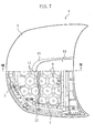
- FIG. 1 shows a hood 1 which is a vehicle hood according to Embodiment 1 of the present invention.
- the hood 1 includes a hood outer panel 3 as an outer plate and a hood reinforcement 5 which is shaped to correspond to the shape of the hood outer panel 3 and bonded to the underside of the hood outer panel 3 with an adhesive 10.
- the hood outer panel 3 is partially cut away to show the hood reinforcement 5.
- the hood 1 When viewed in plan, the hood 1 (the hood outer panel 3 and the hood reinforcement 5) has a convex form at the front end thereof for design purposes. That is, the front part of the vehicle is rounded.
- the hood outer panel 3 and the hood reinforcement 5 are so arranged that space is provided between the underside of the hood outer panel 3 and the top side of the hood reinforcement 5.
- the front part of the hood reinforcement 5 bulges more downward than the other part to make the space at the front part larger than that at the other part.
- the hood reinforcement 5 includes a reinforcing frame 7 of concave section which is arranged at the peripheral portion of the hood reinforcement 5 to dent toward the underside of the hood outer panel 3.
- the reinforcing frame 7 is provided to improve the rigidity of the hood reinforcement 5.
- the hood reinforcement 5 is formed with a concave which is continuously formed along the back part and the side parts thereof except the front part, whereby the reinforcing frame 7 is provided substantially in the form of the letter U when viewed in plan.
- the hood reinforcement 5 is provided with a plurality of dimples 9 which are dented substantially in the form of a conical trapezoid toward the underside of the hood outer panel 3. Further, a plurality of openings 11 are formed around each of the dimples 9 so that the dimples 9 and the openings 11 are arranged in a regular array. Each of the dimples 9 is bonded to the underside of the hood outer panel 3 at the bottom 9a thereof with an adhesive 10.
- a bulge 13 is provided for design purposes.
- the bulge 13 is formed integrally with the hood outer panel 3 and protrudes upward.
- the hood outer panel 3 includes a shelf 15 which substantially horizontally extends outward from the periphery of the bulge 13 by a predetermined distance.
- the shelf 15 is formed at a lower level than the bulge 13. That is, the bulge 13 is formed as if it protrudes from the shelf 15.
- the hood reinforcement 5 further includes a bend 17 which is substantially inverted V-shaped when viewed in section as shown in FIG. 3 and extends along the vehicle width direction when viewed in plan.
- the bend 17 and the bulge 13 are so arranged that the front end of the bulge 13 and the bottom of the bend 17 (end part thereof near the underside of the hood outer panel 3) substantially coincide with each other when viewed in plan.
- the bend 17 is less rigid than the other part of the hood reinforcement 5. Therefore, in a frontal crash, the bend 17 protrudes upward to bend the hood reinforcement 5 in the front to rear direction of the vehicle along the bend 17, thereby forming a bend line 19 extending in the vehicle width direction in the hood outer panel 3 (shown in FIG. 6).
- part of the reinforcing frame 7 located between the front end of the vehicle and the bend 17 has a width L1 in the vehicle width direction (shown in FIG. 4 ) which is larger than a width L2 (shown in FIG. 5) of the other part of the reinforcing frame 7.
- the hood outer panel 3 and the hood reinforcement 5 are bent in the front to rear direction of the vehicle along the bend 17 to form the bend line 19 extending in the vehicle width direction.
- the load applied to the hood outer panel 3 is transferred to the hood reinforcement 5 through the dimples 9. Since the openings 11 weaken the repulsion of the load, damage to the pedestrian head is reduced.
- the front end of the bulge 13 protruding upward from the hood outer panel 3 substantially coincides with the bend 17 of the hood reinforcement 5 when viewed in plan. Therefore, the front end of the highly rigid bulge 13 actively functions as a starting point for bending the hood outer panel 3 surely at a predetermined position. This offers both good design and safety performance against crash.
- the hood outer panel 3 includes the shelf 15 which substantially horizontally extends outward from the periphery of the bulge 13 by a predetermined distance. Therefore, the load of a frontal crash tends to be concentrated on the rear end of the shelf 15, thereby bending the hood outer panel 3 along the bend 17 with great ease.
- part of the reinforcing frame 7 located between the front end of the vehicle and the bend 17 has a larger sectional width than the other part. Therefore, the load of a frontal crash is surely transferred to the bend 17, thereby bending the hood reinforcement 5 along the bend 17 with ease.
- the dimples 9 substantially in the form of a conical trapezoid and the openings 11 are formed in the hood reinforcement 5, impact on pedestrians in a frontal crash is dispersed by the dimples 9 and the openings 11 and the mass of the hood reinforcement 5 is reduced by the openings 11.
- FIGS. 7 to 9 show a vehicle hood 1 according to Embodiment 2 of the present invention.
- the vehicle hood 1 of Embodiment 2 differs from that of Embodiment 1 in the positional relationship between the bend 17 of the hood reinforcement 5 and the bulge 13.
- FIGS. 7 to 9 the same components as those shown in FIGS. 1 to 6 are given with the same reference numerals and a detailed explanation thereof is omitted.
- the bend 17 of the hood reinforcement 5 extending in the vehicle width direction intersects the front part of the bulge 13. That is, the bend 17 and the bulge 13 are so arranged that the bend line 19 is formed along the bend 17 and the edge of the front part of the bulge 13 in a frontal crash.
- the vehicle hood 1 functions in the same manner as described in Embodiment 1.
- the vehicle hood 1 is different from that of Embodiment 1 in that the hood outer panel 3 is bent in the front to rear direction of the vehicle along the bend line 19 formed along the bend 17 and the edge of the front part of the bulge 13 as shown in FIG. 10.
- the front part of the bulge 13 actively functions as a starting point for bending the hood outer panel 3 surely at a predetermined position. This offers both good design and safety performance against crash.
- the vehicle hoods of Embodiments 1 and 2 may be configured as follows.
- the hood 1 includes the shelf 15, but the shelf 15 is not essential for the hood 1. Further, the hood 1 includes the bulge 13, but the present invention is also applicable to the hood which is not provided with the bulge 13. More specifically, in the hood reinforcement 5 of the hood 1 which has a convex form at the front end thereof, part of the reinforcing frame 7 located between the front end of the vehicle and the bend 17 is formed to have a larger sectional width than the other part. As a result, the load of a frontal crash is surely transferred to the bend 17, thereby bending the hood 1 along the bend 17 with reliability. This offers both design and safety performance against crash.
Landscapes
- Engineering & Computer Science (AREA)
- Mechanical Engineering (AREA)
- Chemical & Material Sciences (AREA)
- Combustion & Propulsion (AREA)
- Transportation (AREA)
- Superstructure Of Vehicle (AREA)
Abstract
Description
Claims (6)
- A vehicle hood comprising:a hood outer panel (3);a panel-shaped hood reinforcement (5) which is arranged at the underside of the hood outer panel (3) and includes an integral bend (17) which extends in the vehicle width direction to allow the hood reinforcement (5) to bend in the front to rear direction of the vehicle in a frontal crash, whereinthe hood outer panel (3) includes an integral bulge (13) which protrudes upward andthe bend (17) is arranged near the front end of the bulge (13).
- A vehicle hood according to claim 1, wherein
the bulge (13) and the bend (17) are so arranged that the front end of the bulge (13) and the bend (17) substantially coincide with each other when viewed in plan. - A vehicle hood according to claim 1, wherein
the bulge (13) and the bend (17) are so arranged that a bend line (19) is formed along the bend (17) and the edge of the front part of the bulge (13) when viewed in plan. - A vehicle hood according to claim 2 or 3, wherein
the hood outer panel (3) includes a shelf (15) which substantially horizontally extends outward from the periphery of the bulge (13) by a predetermined distance. - A vehicle hood according to any one of claims 2 to 4, wherein
the hood outer panel (3) and the hood reinforcement (5) each have a convex form at the front ends thereof when viewed in plan,
the hood reinforcement (5) includes a reinforcing frame (7) of concave section which is arranged at the peripheral portion of the hood reinforcement (5) to dent toward the underside of the hood outer panel (3), and
part of the reinforcing frame (7) located between the front end of the vehicle and the bend (17) has a larger sectional width than the other part. - A vehicle hood according to claim 5, wherein
the hood reinforcement (5) is provided with a plurality of dimples (9) which are dented substantially in the form of a conical trapezoid toward the underside of the hood outer panel (3) and a plurality of openings (11) which are formed around the dimples (9).
Applications Claiming Priority (2)
| Application Number | Priority Date | Filing Date | Title |
|---|---|---|---|
| JP2004182383A JP4470607B2 (en) | 2004-06-21 | 2004-06-21 | Vehicle hood structure |
| JP2004182383 | 2004-06-21 |
Publications (2)
| Publication Number | Publication Date |
|---|---|
| EP1609686A1 true EP1609686A1 (en) | 2005-12-28 |
| EP1609686B1 EP1609686B1 (en) | 2008-11-26 |
Family
ID=34936697
Family Applications (1)
| Application Number | Title | Priority Date | Filing Date |
|---|---|---|---|
| EP05010869A Ceased EP1609686B1 (en) | 2004-06-21 | 2005-05-19 | Vehicle hood |
Country Status (5)
| Country | Link |
|---|---|
| US (1) | US7090289B2 (en) |
| EP (1) | EP1609686B1 (en) |
| JP (1) | JP4470607B2 (en) |
| CN (1) | CN100467330C (en) |
| DE (1) | DE602005011201D1 (en) |
Families Citing this family (45)
| Publication number | Priority date | Publication date | Assignee | Title |
|---|---|---|---|---|
| JP4059187B2 (en) * | 2003-10-27 | 2008-03-12 | トヨタ自動車株式会社 | Vehicle hood structure |
| JPWO2006059724A1 (en) * | 2004-12-02 | 2008-06-05 | 株式会社神戸製鋼所 | Body panel structure |
| WO2007025791A1 (en) * | 2005-08-30 | 2007-03-08 | Lanxess Deutschland Gmbh | Passive protection device for a motor vehicle |
| WO2007033145A2 (en) * | 2005-09-12 | 2007-03-22 | Durakon Industries, Inc. | Tonneau cover |
| US7354101B2 (en) * | 2005-12-08 | 2008-04-08 | Ford Global Technologies, Llc | Hood structure with crush initiators |
| JP4719039B2 (en) * | 2006-03-15 | 2011-07-06 | 株式会社神戸製鋼所 | Automotive hood |
| JP5235298B2 (en) * | 2006-12-14 | 2013-07-10 | マツダ株式会社 | Automotive hood structure |
| CN101626943B (en) * | 2007-03-07 | 2011-08-03 | 美铝公司 | Pedestrian safe automotive hood having reinforcing foam |
| US7377580B1 (en) | 2007-03-10 | 2008-05-27 | Nicholas Samir Ekladyous | Multi-tier structure for car body hood |
| US20090026807A1 (en) * | 2007-07-24 | 2009-01-29 | Gm Global Technology Operations, Inc. | Energy-Absorbing Vehicle Hood Assembly with Cushion Inner Structure |
| US7735908B2 (en) * | 2007-07-24 | 2010-06-15 | Gm Global Technology Operations, Inc. | Vehicle hood with sandwich inner structure |
| US7635157B2 (en) * | 2007-09-11 | 2009-12-22 | GM Global Technology Operation, INC | Vehicle hood assembly with rippled cushion support |
| DE102007053171A1 (en) * | 2007-11-08 | 2009-05-14 | Dr. Ing. H.C. F. Porsche Aktiengesellschaft | Bonnet for a motor vehicle |
| US20120298436A1 (en) * | 2010-02-09 | 2012-11-29 | Kim Ho | Engine hood |
| EP2542461A4 (en) * | 2010-03-05 | 2013-09-04 | Shape Corp | Hood pedestrian energy absorber |
| US9022161B2 (en) * | 2010-07-27 | 2015-05-05 | Mahindra & Mahindra Limited | Vehicle bonnet structure for pedestrian protection |
| US8845012B2 (en) * | 2011-03-02 | 2014-09-30 | Honda Motor Co., Ltd. | Vehicle front hood structure |
| WO2012122256A2 (en) | 2011-03-09 | 2012-09-13 | Shape Corp. | Vehicle energy absorber for pedestrian's upper leg |
| US9283923B2 (en) * | 2011-04-26 | 2016-03-15 | Mahindra And Mahindra Limited | Ladder honeycomb hood structure for a motor vehicle for pedestrian protection |
| CN102642562A (en) * | 2012-04-28 | 2012-08-22 | 奇瑞汽车股份有限公司 | Reinforcing structure of automobile engine cover |
| JP5761212B2 (en) * | 2013-01-15 | 2015-08-12 | トヨタ自動車株式会社 | Vehicle hood structure |
| US9216771B2 (en) | 2013-09-06 | 2015-12-22 | Toyota Motor Engineering & Manufacturing North America, Inc. | Hood structure for automotive vehicle |
| JP5870141B2 (en) | 2014-03-26 | 2016-02-24 | 株式会社神戸製鋼所 | Automotive hood structure and hood inner panel |
| US20150323034A1 (en) * | 2014-05-08 | 2015-11-12 | GM Global Technology Operations LLC | Energy absorber system and vehicle |
| US9248866B2 (en) * | 2014-06-13 | 2016-02-02 | Toyota Motor Engineering & Manufacturing North America, Inc. | Hood assembly |
| US9381879B2 (en) * | 2014-11-12 | 2016-07-05 | GM Global Technology Operations LLC | Local energy absorber |
| JP2017105427A (en) * | 2015-12-04 | 2017-06-15 | 株式会社神戸製鋼所 | Vehicular hood |
| US9783236B1 (en) * | 2015-12-14 | 2017-10-10 | Waymo Llc | Vehicle bonnet constructions for reducing impact forces |
| US10092055B2 (en) | 2016-01-06 | 2018-10-09 | GM Global Technology Operations LLC | Local energy absorber |
| US10144457B2 (en) * | 2016-03-31 | 2018-12-04 | Kobe Steel, Ltd. | Vehicle hood |
| JP6718726B2 (en) * | 2016-03-31 | 2020-07-08 | 株式会社神戸製鋼所 | Vehicle hood |
| USD817823S1 (en) * | 2016-08-23 | 2018-05-15 | Bayerische Motoren Werke Aktiengesellschaft | Front bumper for a vehicle |
| USD823196S1 (en) * | 2017-01-13 | 2018-07-17 | Ford Global Technologies, Llc | Vehicle hood |
| USD824824S1 (en) * | 2017-01-26 | 2018-08-07 | GM Global Technology Operations LLC | Vehicle hood |
| USD824825S1 (en) * | 2017-03-16 | 2018-08-07 | GM Global Technology Operations LLC | Vehicle hood |
| ZAA201701739S (en) * | 2017-05-10 | 2019-03-27 | Bayerische Motoren Werke Ag | Motor vehicles |
| USD852105S1 (en) * | 2017-06-15 | 2019-06-25 | Jaguar Land Rover Limited | Roof for a vehicle |
| USD838640S1 (en) * | 2017-10-04 | 2019-01-22 | Ford Global Technologies, Llc | Vehicle hood |
| USD839801S1 (en) * | 2017-11-01 | 2019-02-05 | Ford Global Technologies, Llc | Vehicle hood |
| USD841541S1 (en) * | 2017-11-28 | 2019-02-26 | GM Global Technology Operations LLC | Vehicle hood |
| WO2020145198A1 (en) * | 2019-01-10 | 2020-07-16 | 日本製鉄株式会社 | Motor vehicle inner panel and motor vehicle panel |
| USD908553S1 (en) * | 2019-06-27 | 2021-01-26 | Volkswagen Aktiengesellschaft | Radiator grille for vehicle |
| USD953948S1 (en) * | 2019-10-10 | 2022-06-07 | Ford Global Technologies, Llc | Vehicle hood |
| USD924754S1 (en) * | 2020-01-17 | 2021-07-13 | Paccar Inc | Top panel for a truck hood |
| USD924755S1 (en) * | 2020-01-22 | 2021-07-13 | Paccar Inc | Top panel for a truck hood |
Citations (3)
| Publication number | Priority date | Publication date | Assignee | Title |
|---|---|---|---|---|
| JPS59176166A (en) | 1983-03-25 | 1984-10-05 | Nissan Motor Co Ltd | Coupling structure of bulge hatch and hood |
| JP2003191865A (en) | 2001-12-26 | 2003-07-09 | Mazda Motor Corp | Bonnet structure for vehicle |
| EP1357018A1 (en) * | 2000-12-13 | 2003-10-29 | Kabushiki Kaisha Kobe Seiko Sho | Panel structure for car body hood |
Family Cites Families (9)
| Publication number | Priority date | Publication date | Assignee | Title |
|---|---|---|---|---|
| FR2621677B1 (en) * | 1987-10-13 | 1990-06-22 | Heuliez Henri France Design | RIGID STRUCTURE FOR REALIZING THREE-DIMENSIONAL PANELS OR ELEMENTS |
| US5124191A (en) * | 1991-03-11 | 1992-06-23 | Aluminum Company Of America | Structural panel |
| US5538094A (en) * | 1994-01-11 | 1996-07-23 | Aluminum Company Of America | Panel reinforcement structure |
| JP3871744B2 (en) * | 1996-10-25 | 2007-01-24 | 本田技研工業株式会社 | Synthetic resin panels for automobiles |
| US7360822B2 (en) * | 1998-02-04 | 2008-04-22 | Oakwood Energy Management, Inc. | Modular energy absorber and method for configuring same |
| US20020003054A1 (en) * | 2000-07-10 | 2002-01-10 | Teruo Kamada | Vehicular body panel or component part and method for manufacturing same |
| JP4076487B2 (en) * | 2003-09-25 | 2008-04-16 | トヨタ自動車株式会社 | Vehicle hood structure |
| JP4059187B2 (en) * | 2003-10-27 | 2008-03-12 | トヨタ自動車株式会社 | Vehicle hood structure |
| US7225542B2 (en) * | 2004-01-23 | 2007-06-05 | General Motors Corporation | Vehicle body compartment lid method of manufacturing |
-
2004
- 2004-06-21 JP JP2004182383A patent/JP4470607B2/en not_active Expired - Fee Related
-
2005
- 2005-05-19 EP EP05010869A patent/EP1609686B1/en not_active Ceased
- 2005-05-19 DE DE602005011201T patent/DE602005011201D1/en not_active Expired - Fee Related
- 2005-06-02 CN CNB2005100742708A patent/CN100467330C/en not_active Expired - Fee Related
- 2005-06-15 US US11/154,423 patent/US7090289B2/en not_active Expired - Fee Related
Patent Citations (3)
| Publication number | Priority date | Publication date | Assignee | Title |
|---|---|---|---|---|
| JPS59176166A (en) | 1983-03-25 | 1984-10-05 | Nissan Motor Co Ltd | Coupling structure of bulge hatch and hood |
| EP1357018A1 (en) * | 2000-12-13 | 2003-10-29 | Kabushiki Kaisha Kobe Seiko Sho | Panel structure for car body hood |
| JP2003191865A (en) | 2001-12-26 | 2003-07-09 | Mazda Motor Corp | Bonnet structure for vehicle |
Non-Patent Citations (1)
| Title |
|---|
| PATENT ABSTRACTS OF JAPAN vol. 2003, no. 11 5 November 2003 (2003-11-05) * |
Also Published As
| Publication number | Publication date |
|---|---|
| CN1712299A (en) | 2005-12-28 |
| EP1609686B1 (en) | 2008-11-26 |
| JP2006001500A (en) | 2006-01-05 |
| US20050280287A1 (en) | 2005-12-22 |
| JP4470607B2 (en) | 2010-06-02 |
| CN100467330C (en) | 2009-03-11 |
| US7090289B2 (en) | 2006-08-15 |
| DE602005011201D1 (en) | 2009-01-08 |
Similar Documents
| Publication | Publication Date | Title |
|---|---|---|
| EP1609686B1 (en) | Vehicle hood | |
| US6179364B1 (en) | Bonnet for automobile | |
| US7108092B2 (en) | Front grill impact-absorbing structure for a vehicle | |
| EP1518780B1 (en) | Vehicle front-body structure | |
| JP6443469B2 (en) | Vehicle front structure | |
| EP1527984B1 (en) | Hood structure for vehicle | |
| EP2195193B1 (en) | Lamp mounting structure and vehicle to which lamp is mounted with the use of the same | |
| US8091941B2 (en) | Lower structure of vehicle body rear part | |
| US8308214B2 (en) | Lower structure of vehicle body rear part | |
| JP2005145224A (en) | Hood structure for vehicle | |
| CN110920755A (en) | Front body structure of vehicle | |
| EP1625977A2 (en) | Bumper reinforcement for an automobile | |
| CN115991244A (en) | Engine cover structure of vehicle | |
| CN109895855A (en) | Body construction | |
| EP0908372B1 (en) | Construction of root portion of front side member | |
| EP1371509A1 (en) | Vehicle windshield mounting structure | |
| US6979053B2 (en) | Reinforcement structure for front end module carrier | |
| JP4775068B2 (en) | Hood structure | |
| JP2019177814A (en) | Vehicle body structure | |
| JP4457909B2 (en) | Cowl louva | |
| US6435603B1 (en) | Structure for front part of automotive vehicle body | |
| JP3622715B2 (en) | Body front structure | |
| US11318997B2 (en) | Hood structure | |
| JP4200941B2 (en) | Vehicle hood structure | |
| JP6558384B2 (en) | Vehicle front structure |
Legal Events
| Date | Code | Title | Description |
|---|---|---|---|
| PUAI | Public reference made under article 153(3) epc to a published international application that has entered the european phase |
Free format text: ORIGINAL CODE: 0009012 |
|
| AK | Designated contracting states |
Kind code of ref document: A1 Designated state(s): AT BE BG CH CY CZ DE DK EE ES FI FR GB GR HU IE IS IT LI LT LU MC NL PL PT RO SE SI SK TR |
|
| AX | Request for extension of the european patent |
Extension state: AL BA HR LV MK YU |
|
| 17P | Request for examination filed |
Effective date: 20060419 |
|
| AKX | Designation fees paid |
Designated state(s): DE |
|
| GRAP | Despatch of communication of intention to grant a patent |
Free format text: ORIGINAL CODE: EPIDOSNIGR1 |
|
| GRAS | Grant fee paid |
Free format text: ORIGINAL CODE: EPIDOSNIGR3 |
|
| GRAA | (expected) grant |
Free format text: ORIGINAL CODE: 0009210 |
|
| AK | Designated contracting states |
Kind code of ref document: B1 Designated state(s): DE |
|
| REF | Corresponds to: |
Ref document number: 602005011201 Country of ref document: DE Date of ref document: 20090108 Kind code of ref document: P |
|
| PLBE | No opposition filed within time limit |
Free format text: ORIGINAL CODE: 0009261 |
|
| STAA | Information on the status of an ep patent application or granted ep patent |
Free format text: STATUS: NO OPPOSITION FILED WITHIN TIME LIMIT |
|
| 26N | No opposition filed |
Effective date: 20090827 |
|
| PG25 | Lapsed in a contracting state [announced via postgrant information from national office to epo] |
Ref country code: DE Free format text: LAPSE BECAUSE OF NON-PAYMENT OF DUE FEES Effective date: 20091201 |