EP1609660A1 - Power supply apparatus capable of detecting abnormality in current flowing in drive circuit - Google Patents
Power supply apparatus capable of detecting abnormality in current flowing in drive circuit Download PDFInfo
- Publication number
- EP1609660A1 EP1609660A1 EP05012766A EP05012766A EP1609660A1 EP 1609660 A1 EP1609660 A1 EP 1609660A1 EP 05012766 A EP05012766 A EP 05012766A EP 05012766 A EP05012766 A EP 05012766A EP 1609660 A1 EP1609660 A1 EP 1609660A1
- Authority
- EP
- European Patent Office
- Prior art keywords
- current
- power supply
- drive
- abnormal
- motor
- Prior art date
- Legal status (The legal status is an assumption and is not a legal conclusion. Google has not performed a legal analysis and makes no representation as to the accuracy of the status listed.)
- Granted
Links
- 230000005856 abnormality Effects 0.000 title claims abstract description 76
- 238000001514 detection method Methods 0.000 claims abstract description 68
- 238000005070 sampling Methods 0.000 claims abstract description 21
- 230000002159 abnormal effect Effects 0.000 claims description 69
- 238000010586 diagram Methods 0.000 description 12
- 238000006243 chemical reaction Methods 0.000 description 8
- 238000000034 method Methods 0.000 description 7
- 230000001172 regenerating effect Effects 0.000 description 6
- 230000007423 decrease Effects 0.000 description 3
- 230000007274 generation of a signal involved in cell-cell signaling Effects 0.000 description 2
- 230000010354 integration Effects 0.000 description 2
- 238000010248 power generation Methods 0.000 description 2
- HBBGRARXTFLTSG-UHFFFAOYSA-N Lithium ion Chemical compound [Li+] HBBGRARXTFLTSG-UHFFFAOYSA-N 0.000 description 1
- PXHVJJICTQNCMI-UHFFFAOYSA-N Nickel Chemical compound [Ni] PXHVJJICTQNCMI-UHFFFAOYSA-N 0.000 description 1
- 230000001133 acceleration Effects 0.000 description 1
- 229910001416 lithium ion Inorganic materials 0.000 description 1
- 229910000652 nickel hydride Inorganic materials 0.000 description 1
- 238000013021 overheating Methods 0.000 description 1
- 230000035939 shock Effects 0.000 description 1
Images


Classifications
-
- B—PERFORMING OPERATIONS; TRANSPORTING
- B60—VEHICLES IN GENERAL
- B60L—PROPULSION OF ELECTRICALLY-PROPELLED VEHICLES; SUPPLYING ELECTRIC POWER FOR AUXILIARY EQUIPMENT OF ELECTRICALLY-PROPELLED VEHICLES; ELECTRODYNAMIC BRAKE SYSTEMS FOR VEHICLES IN GENERAL; MAGNETIC SUSPENSION OR LEVITATION FOR VEHICLES; MONITORING OPERATING VARIABLES OF ELECTRICALLY-PROPELLED VEHICLES; ELECTRIC SAFETY DEVICES FOR ELECTRICALLY-PROPELLED VEHICLES
- B60L3/00—Electric devices on electrically-propelled vehicles for safety purposes; Monitoring operating variables, e.g. speed, deceleration or energy consumption
- B60L3/0023—Detecting, eliminating, remedying or compensating for drive train abnormalities, e.g. failures within the drive train
-
- B—PERFORMING OPERATIONS; TRANSPORTING
- B60—VEHICLES IN GENERAL
- B60L—PROPULSION OF ELECTRICALLY-PROPELLED VEHICLES; SUPPLYING ELECTRIC POWER FOR AUXILIARY EQUIPMENT OF ELECTRICALLY-PROPELLED VEHICLES; ELECTRODYNAMIC BRAKE SYSTEMS FOR VEHICLES IN GENERAL; MAGNETIC SUSPENSION OR LEVITATION FOR VEHICLES; MONITORING OPERATING VARIABLES OF ELECTRICALLY-PROPELLED VEHICLES; ELECTRIC SAFETY DEVICES FOR ELECTRICALLY-PROPELLED VEHICLES
- B60L2210/00—Converter types
- B60L2210/20—AC to AC converters
-
- H—ELECTRICITY
- H02—GENERATION; CONVERSION OR DISTRIBUTION OF ELECTRIC POWER
- H02H—EMERGENCY PROTECTIVE CIRCUIT ARRANGEMENTS
- H02H7/00—Emergency protective circuit arrangements specially adapted for specific types of electric machines or apparatus or for sectionalised protection of cable or line systems, and effecting automatic switching in the event of an undesired change from normal working conditions
- H02H7/08—Emergency protective circuit arrangements specially adapted for specific types of electric machines or apparatus or for sectionalised protection of cable or line systems, and effecting automatic switching in the event of an undesired change from normal working conditions for dynamo-electric motors
- H02H7/0833—Emergency protective circuit arrangements specially adapted for specific types of electric machines or apparatus or for sectionalised protection of cable or line systems, and effecting automatic switching in the event of an undesired change from normal working conditions for dynamo-electric motors for electric motors with control arrangements
-
- H—ELECTRICITY
- H02—GENERATION; CONVERSION OR DISTRIBUTION OF ELECTRIC POWER
- H02H—EMERGENCY PROTECTIVE CIRCUIT ARRANGEMENTS
- H02H7/00—Emergency protective circuit arrangements specially adapted for specific types of electric machines or apparatus or for sectionalised protection of cable or line systems, and effecting automatic switching in the event of an undesired change from normal working conditions
- H02H7/10—Emergency protective circuit arrangements specially adapted for specific types of electric machines or apparatus or for sectionalised protection of cable or line systems, and effecting automatic switching in the event of an undesired change from normal working conditions for converters; for rectifiers
- H02H7/12—Emergency protective circuit arrangements specially adapted for specific types of electric machines or apparatus or for sectionalised protection of cable or line systems, and effecting automatic switching in the event of an undesired change from normal working conditions for converters; for rectifiers for static converters or rectifiers
- H02H7/122—Emergency protective circuit arrangements specially adapted for specific types of electric machines or apparatus or for sectionalised protection of cable or line systems, and effecting automatic switching in the event of an undesired change from normal working conditions for converters; for rectifiers for static converters or rectifiers for inverters, i.e. DC/AC converters
- H02H7/1227—Emergency protective circuit arrangements specially adapted for specific types of electric machines or apparatus or for sectionalised protection of cable or line systems, and effecting automatic switching in the event of an undesired change from normal working conditions for converters; for rectifiers for static converters or rectifiers for inverters, i.e. DC/AC converters responsive to abnormalities in the output circuit, e.g. short circuit
-
- Y—GENERAL TAGGING OF NEW TECHNOLOGICAL DEVELOPMENTS; GENERAL TAGGING OF CROSS-SECTIONAL TECHNOLOGIES SPANNING OVER SEVERAL SECTIONS OF THE IPC; TECHNICAL SUBJECTS COVERED BY FORMER USPC CROSS-REFERENCE ART COLLECTIONS [XRACs] AND DIGESTS
- Y02—TECHNOLOGIES OR APPLICATIONS FOR MITIGATION OR ADAPTATION AGAINST CLIMATE CHANGE
- Y02T—CLIMATE CHANGE MITIGATION TECHNOLOGIES RELATED TO TRANSPORTATION
- Y02T10/00—Road transport of goods or passengers
- Y02T10/60—Other road transportation technologies with climate change mitigation effect
- Y02T10/72—Electric energy management in electromobility
Definitions
- the present invention relates to a power supply apparatus and particularly to a power supply apparatus having the function of detecting an abnormality in electric current flowing in a drive circuit mounted on the power supply apparatus.
- Hybrid vehicles and electric vehicles have recently been of great interest as environment-friendly motor vehicles.
- a hybrid vehicle has, as its motive power sources, a DC (direct current) power supply, an inverter and a motor driven by the inverter in addition to a conventional engine. More specifically, the engine is driven to secure the motive power source and a DC voltage from the DC power supply is converted by the inverter into an AC (alternating current) voltage to be used for rotating the motor and thereby securing the motive power source as well.
- An electric vehicle refers to a motor vehicle that has, as its motive power sources, a DC power supply, an inverter and a motor driven by the inverter.
- the hybrid vehicles and electric vehicles generally use a high-voltage power supply for producing high power.
- overload could cause overheating to incur the danger that an electric motor seizes up or burns out.
- an electric leakage occurs, there arises the danger of an electrical shock.
- a safety device is thus required for avoiding these dangers (for example, see Japanese Patent Laying-Open No. 07-123504).
- Fig. 11 is a block diagram showing a configuration of a safety device for electric vehicles (hereinafter referred to as EV safety device) disclosed in Japanese Patent Laying-Open No. 07-123504.
- EV safety device a safety device for electric vehicles
- the EV safety device is configured to have a switch 150 on a power feeding path L extending from a DC power supply 110 to a load circuit 130 and open/close switch 150 according to an external signal that is input from a protection circuit 140 to a drive circuit 151.
- a current detector 141 detects electric current passing through power feeding path L.
- the output of current detector 141 is amplified by a current detection circuit 142 and input to a control circuit 143.
- control circuit 143 drives an output relay circuit 144 and turns off a contact r of switch 150 through drive circuit 151.
- the operating time refers to a time limit from the time when the value of the electric current detected by current detector 141 exceeds the rated electric current.
- the operating time is set to allow switch 150 to be opened if the detected current value does not fall to or below the rated current at the time when the operating time has passed. Further, the operating time is set, according to the magnitude of the passing electric current, so that the operating time is shorter in an inversely proportional manner as the current value is larger for example. If the detected electric current falls to or below the rated current within the time limit of the operating time, switch 150 is not opened. Then, the next time the detected current exceeds the rated current, the time limit is newly set.
- the power feeding to load circuit 130 is stopped to accordingly afford protection against overcurrent.
- the passing current has a sinusoidal current waveform in a normal operation.
- the passing current has its waveform considerably different from the one the current should have.
- Examples of the passing current in an abnormal state include electric current having a current waveform temporarily exceeding the rated current to a considerably great degree and electric current having a current waveform continuing around the uppermost level of the sinusoidal wave.
- a large load is exerted temporarily on the inverter depending on the magnitude of the passing current and the period of time during which the current flows, which could break the inverter.
- the passing current continuously flows having its level around the uppermost level of the sinusoidal wave the load with the maximum level in a normal state is continuously exerted on the inverter, which could also break the inverter.
- any abnormal electric current that flows with its level temporarily exceeding the rated current to a considerably great degree is regarded as abnormal if such abnormal current flows for more than a predetermined operating time.
- the threshold value is set at the uppermost level of the sinusoidal wave, it is difficult to accurately detect the abnormal current flowing at and around the uppermost level of the sinusoidal wave, since the time-limit setting is initialized when the passing current falls to or below the threshold value within the time limit of the operating time and the time limit is newly set the next time the current exceeds the threshold value.
- the above-described method of detecting an abnormality has a problem that the pattern of abnormal current that is not preferable for the inverter does not necessarily match the result of determining whether an abnormality occurs or not.
- An object of the present invention is to provide a power supply apparatus that can accurately detect an abnormality in electric current flowing in a drive circuit that drives a load.
- a power supply apparatus includes: a power supply; a drive circuit receiving electric power from the power supply to drive a load circuit; and an abnormal current detection circuit detecting an abnormality in drive current flowing in the drive circuit.
- the abnormal current detection circuit detects that a current integral of the drive current is larger than a predetermined threshold to determine that the drive current is abnormal.
- the power supply apparatus further includes a switch performing a switching operation to electrically connect/disconnect the power supply and the drive circuit to/from each other.
- the abnormal current detection circuit determines that the drive current is abnormal
- the abnormal current detection circuit controls the switching operation to electrically disconnect the power supply and the drive circuit from each other.
- the predetermined threshold is lower than a current integral of the drive current that causes the drive circuit to be broken.
- the abnormal current detection circuit includes: a current detection unit for sampling the drive current at every predetermined calculation cycle; a current integral calculation unit for integrating the sampled drive current over a plurality of the predetermined calculation cycles consumed for the sampling to calculate the current integral of the drive current; and an abnormality determination unit for determining whether the current integral of the drive current is larger than the predetermined threshold, detecting that the current integral of the drive current is larger than the predetermined threshold and determining that the drive current is abnormal.
- the predetermined calculation cycle includes a cycle of a highest operating speed at which the abnormal current detection circuit can operate.
- the load circuit includes an AC motor
- the abnormal current detection circuit includes a mode determination unit for determining a control mode of the AC motor.
- the mode determination unit determines a control mode of the AC motor when the drive current that is out of a normal operating range flows.
- the abnormality determination unit adjusts the predetermined threshold to an appropriate threshold that is appropriate for the determined control mode, determines whether the current integral of the drive current is larger than the appropriate threshold, detects that the current integral of the drive current is larger than the appropriate threshold, and determines that the drive current is abnormal.
- the mode determination unit determines the control mode among control modes with respective carrier frequencies different from each other.
- the abnormality determination unit adjusts the threshold according to the carrier frequency of the determined control mode.
- the present invention based on the fact that the current integral of the drive current exceeds a predetermined threshold, it is determined that the drive current is abnormal. Therefore, as compared with the conventional abnormality determination method determining that the passing current is abnormal based on the phase thereof in a single operating time period, the present invention can more accurately detect abnormal current that overloads the drive circuit.
- the predetermined threshold used for determining whether the drive current is abnormal or not is set based on the load on the drive circuit that is exerted when an abnormality occurs. Therefore, regardless of the waveform of the abnormal current, the drive circuit can surely be protected.
- the predetermined threshold is adjusted according to the control mode of the AC motor. Therefore, an abnormality can precisely be detected regardless of the waveform of the abnormal current to strength the protection of the drive circuit.
- Fig. 1 is a schematic block diagram of a power supply apparatus according to a first embodiment of the present invention.
- the power supply apparatus includes a DC power supply B, a voltage sensor 10, an inverter 12, a current sensor 20, a resolver 30, and a control device 40.
- An AC motor M1 is a drive motor that generates torque for driving drive wheels of a hybrid vehicle or electric vehicle.
- AC motor M1 also serves as an electric generator driven by an engine and as an electric motor for the engine to start the engine for example.
- Inverter 12 includes a U phase arm 14, a V phase arm 16 and a W phase arm 18.
- U phase arm 14, V phase arm 16 and W phase arm 18 are provided in parallel between a power supply line and a ground line.
- U phase arm 14 is comprised ofNPN transistors Q1, Q2 connected in series
- V phase arm 16 is comprised ofNPN transistors Q3, Q4 connected in series
- W phase arm 18 is comprised ofNPN transistors Q5, Q6 connected in series.
- diodes D 1 to D6 for allowing current to flow from the emitter to the collector are connected respectively.
- each phase arm is connected to one end of a corresponding one of phase coils of AC motor M1.
- AC motor M1 is a three-phase permanent-magnet motor and, one end of a U phase coil, one end of a V phase coil and one end of a W phase coil are connected at the common central junction, while the other end of the U phase coil is connected to an intermediate point between NPN transistors Q1, Q2, the other end of the V phase coil is connected to an intermediate point between NPN transistors Q3, Q4, and the other end of the W phase coil is connected to an intermediate point between NPN transistors Q5, Q6.
- DC power supply B is comprised of secondary or rechargeable cell(s), for example, of nickel hydride or lithium ion.
- Voltage sensor 10 detects a voltage Vm that is output from DC power supply B to output the detected voltage Vm to control device 40.
- System relays SR1, SR2 are turned on/off according to a signal SE from control device 40.
- inverter 12 converts the DC voltage into an AC voltage based on a drive signal DRV from control device 40 so as to drive AC motor M1. Accordingly, AC motor M1 is driven to generate torque specified by a torque command value TR.
- inverter 12 converts an AC voltage generated by AC motor M1 into a DC voltage based on signal DRV from control device 40 and supplies the resultant DC voltage to DC power supply B.
- the regenerative braking here includes braking accompanied by regenerative power generation that is effected when a driver of the hybrid vehicle or electric vehicle steps on the foot brake as well as deceleration (or stop of acceleration) accompanied by regenerative power generation that is effected when the driver releases the accelerator pedal without operating the foot brake.
- Current sensor 20 detects motor current MCRT flowing through AC motor M1 to output the detected motor current MCRT to control device 40.
- Resolver 30 is attached to the rotational shaft of AC motor M1 to detect rotational angle ⁇ n of the rotor of AC motor M1 and output the detected angle to control device 40.
- Control device 40 receives, from an external ECU (Electrical Control Unit), torque command value TR and motor revolution number (number of revolutions of the motor) MRN, receives voltage Vm from voltage sensor 10, receives motor current MCRT from current sensor 20, and receives rotational angle ⁇ n from resolver 30.
- ECU Electronic Control Unit
- motor revolution number number of revolutions of the motor
- Control device 40 uses rotational angle ⁇ n from resolver 30, torque command value TR and motor current MCRT to generate drive signal DRV for driving NPN transistors Q1-Q6 of inverter 12 and output the generated drive signal DRV to inverter 12.
- control device 40 in the regenerative braking mode of the hybrid vehicle or electric vehicle having the power supply apparatus mounted thereon, control device 40 generates, based on rotational angle ⁇ n, torque command value TR and motor current MCRT, drive signal DRV for converting an AC voltage generated by AC motor M 1 into a DC voltage, and outputs the generated drive signal DRV to inverter 12.
- drive signal DRV switching of NPN transistors Q 1 to Q6 of inverter 12 is controlled by drive signal DRV. Accordingly, inverter 12 converts the AC voltage generated by AC motor M1 into the DC voltage and supplies the DC voltage to DC power supply B.
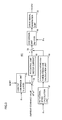
- Fig. 2 is a block diagram of control device 40 in Fig. 1.
- control device 40 includes an inverter control circuit 401 and an abnormal current detection circuit 402a.
- Inverter control circuit 401 generates, based on rotational angle ⁇ n, torque command value TR and motor current MCRT, drive signal DRV for turning on/off NPN transistors Q1 to Q6 of inverter 12 when AC motor M1 is driven, and outputs the generated signal DRV to inverter 12.
- inverter control circuit 401 inverter control circuit 401 generates, based on rotational angle ⁇ n, torque command value TR and motor current MCRT, drive signal DRV for converting the AC voltage generated by AC motor M1 into the DC voltage, and outputs the generated drive signal DRV to inverter 12.
- Abnormal current detection circuit 402a samples motor current MCRT detected by current sensor 20 and detects an abnormality occurring in motor current MCRT based on the level of the sampled current.
- the circuit When abnormal current detection circuit 402a detects an abnormality in motor current MCRT, the circuit generates signal SE for turning off system relays SR1, SR2 and outputs the generated signal SE to system relays SR1, SR2. Further, abnormal current detection circuit 402a generates a signal AL for notifying a user of the occurrence of the abnormality and outputs the generated signal AL to the outside of the power supply apparatus.
- Fig. 3 is a control block diagram of inverter control circuit 401 shown in Fig. 2.
- inverter control circuit 401 includes a current conversion unit 51, a subtracter 52, a PI control unit 53, a rotational speed calculation unit 57, a speed-electromotive-force predictive calculation unit 58, an adder 54, a conversion unit 55, and a drive signal generation unit 56.
- Current conversion unit 51 uses rotational angle ⁇ n that is output from resolver 30 to perform three-to-two phase conversion on motor current MCRT detected by current sensor 20. Specifically, current conversion unit 51 uses rotational angle ⁇ n to transform three-phase motor current MCRT flowing in each phase of AC motor M1 into current values Id, Iq of d-axis and q-axis current to output the resultant values to subtracter 52.
- Subtracter 52 subtracts, from current command values Id*, Iq* for AC motor M1 to output the torque specified by torque command value TR, current values Id, Iq from current conversion unit 51 to determine deviations ⁇ Id, ⁇ Iq.
- PI control unit 53 uses a PI gain for deviations ⁇ Id, ⁇ Iq to calculate a control amount for adjusting the motor current.
- Rotational speed calculation unit 57 calculates, based on rotational angle ⁇ n from resolver 30, the rotational speed of AC motor M1 to output the calculated rotational speed to speed-electromotive-force predictive calculation unit 58.
- Speed-electromotive-force predictive calculation unit 58 calculates a predicted value of speed electromotive force based on the rotational speed from rotational speed calculation unit 57.
- Adder 54 calculates the sum of the control amount for adjusting the motor current from PI control unit 53 and the predicted value of the speed electromotive force from speed-electromotive-force predictive calculation unit 58 to determine voltage control amounts Vd, Vq to be applied to the d and q axes.
- Conversion unit 55 uses control amounts Vd, Vq of the voltage applied to the d axis and the q axis to convert the control amounts into control amounts of the voltage applied to the three-phase coils of AC motor M1.
- Drive signal generation unit 56 generates drive signal DRV based on the output from conversion unit 55.
- Fig. 4 is a block diagram of abnormal current detection circuit 402a shown in Fig. 2.
- abnormal current detection circuit 402a includes a current detection unit 60a, a current integral calculation unit 62, an abnormality determination unit 64a, a relay drive unit 66, and a notification unit 68.
- Current detection unit 60a receives motor current MCRT detected by current sensor 20 to sample motor current MCRT at every predetermined calculation cycle.
- the predetermined calculation cycle may arbitrarily be set by a user. It is preferable, in terms of accuracy in detecting an abnormality, the predetermined calculation cycle is set to correspond to a cycle of the highest processing speed of a CPU (Central Processing Unit) with which control device 40 is configured.
- the sampled motor current MCRT is output to current integral calculation unit 62.
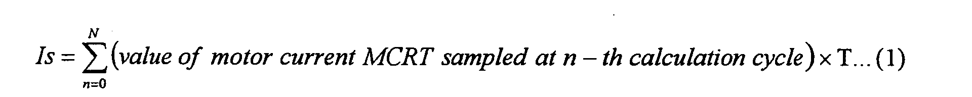
- Current integral calculation unit 62 calculates the integral of the sampled motor current MCRT over a period of time consumed for sampling (sampling period) to determine current integral Is.
- current integral Is is represented by the following expression where T represents a sampling period corresponding to one of the predetermined calculation cycles.
- Current integral Is determined by expression (1) is output to abnormality determination unit 64a.
- abnormality determination unit 64a determines whether there is an abnormality in motor current MCRT, based on whether current integral Is is larger or smaller than a predetermined threshold Is_std that is used as a reference value for detecting an abnormality.
- Fig. 5 is a schematic for illustrating the operation of detecting an abnormality by abnormal current detection circuit 402a shown in Fig. 4.
- motor current MCRT when the power supply apparatus is in a normal state, motor current MCRT has the sinusoidal current waveform as indicated by the dotted line.
- the current waveform irregularly oscillates relative to the sinusoidal waveform as indicated by the solid line.
- the current continues to irregularly oscillate at a higher level than that of the normal current, overcurrent continuously flows in inverter 12, which could break inverter 12.
- abnormal current detection circuit 402a calculates the magnitude of a load exerted by motor current MCRT on inverter 12 to detect an abnormality in motor current MCRT based on the calculated magnitude of the load.
- the current waveform of motor current MCRT in an abnormal state includes, in addition to the waveform kept around the upper-limit level of the sinusoidal wave as shown in Fig. 5, any waveform momentarily indicating a high level for example, the current waveform is integrated in the same manner to determine current integral Is.
- the common reference that is the magnitude of the load on inverter 12 can be used for making comparisons between waveforms.
- Abnormality determination unit 64a defines current integral Is that exerts a predetermined load on inverter 12 as predetermined threshold Is_std, and detects that current integral Is exceeds this threshold Is_std to determine that motor current MCRT has an abnormality.
- this predetermined threshold Is_std lower than current integral Is that could cause inverter 12 to break.
- an abnormality in motor current MCRT is detected based on the fact that the load on inverter 12 exceeds threshold Is_std.
- the motor current is not regarded as abnormal.
- the abnormal current oscillating around the upper-limit level of the sinusoidal wave that has been difficult to detect by the conventional abnormality detection method can surely be detected.
- the accuracy in detecting an abnormality can be improved.
- abnormality determination unit 64a determines that motor current MCRT is abnormal
- abnormality determination unit 64a generates a detection signal DET indicating that the abnormality is detected and outputs the generated detection signal DET to relay drive unit 66 and notification unit 68.
- relay drive unit 66 In response to detection signal DET, relay drive unit 66 generates signal SE for turning off system relays SR1, SR2 and outputs the signal to system relays SR1, SR2. As system relays SR1, SR2 are turned off according to signal SE, DC power supply B is disconnected from the power supply apparatus to prevent the abnormal current from flowing into inverter 12.
- notification unit 68 In response to detection signal DET, notification unit 68 generates a signal AL that is an alarm output for notifying a user of the occurrence of the abnormality and outputs the generated signal AL to the outside of the power supply apparatus.
- This output signal AL is transferred to display means (not shown) mounted on the vehicle to be converted into sound or image signal and output.
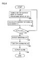
- Fig. 6 is a flowchart for illustrating the operation of detecting abnormal current of the power supply apparatus according to the first embodiment.
- current detection unit 60a samples motor current MCRT (step S01).
- the sampling cycle is set to a cycle of the highest processing speed of the CPU.
- the sampled motor current MCRT is output to current integral calculation unit 62.
- current integral calculation unit 62 integrates the sampling value over each predetermined calculation cycle (sampling period T) to calculate current integral Is (step S02).
- the calculated current integral Is is output to abnormality determination unit 64a.
- abnormality determination unit 64a determines whether current integral Is is larger than threshold Is_std (step S03).
- step S03 when it is determined that current integral Is is larger than threshold Is_std, abnormality determination unit 64a generates detection signal DET indicating that an abnormality in motor current MCRT is detected, and then outputs the generated detection signal DET to relay drive unit 66 and notification unit 68 (step S04).
- Relay drive unit 66 receives detection signal DET to generate signal SE for turning off system relays SR1, SR2 and output the generated signal to system relays SR1, SR2. Accordingly, system relays SR1, SR2 are turned off (step S05).
- Notification unit 68 receives detection signal DET to generate signal AL and output the signal to display means (not shown) provided outside the power supply apparatus (step S06). Thus, the user is informed of the occurrence of the abnormal current.
- step S03 when it is determined that current integral Is is equal to or smaller than threshold Is_std, the process returns to step S01 to continue the operation of calculating the current integral and comparison with threshold Is_std in steps S01 and S02.
- the current integral of the motor current is calculated and it is determined that the motor current is abnormal based on the fact that the calculated current integral exceeds a predetermined threshold. Therefore, any abnormal current that could exert an excessive load on the inverter can be detected regardless of the waveform of the abnormal current, and thus reliability in terms of protection of the inverter can be improved.
- Fig. 7 is a block diagram of an abnormal current detection circuit of a power supply apparatus according to a second embodiment.
- the power supply apparatus of the present embodiment is identical to the power supply apparatus shown in Fig. 1 except that abnormality detection circuit 402a is replaced with an abnormality detection circuit 402b, and the detailed description of the common component is not repeated here.
- abnormal current detection circuit 402b includes a current detection unit 60b, a current integral calculation unit 62, an abnormality determination unit 64b, a relay drive unit 66, a notification unit 68, and a control mode determination unit 70.
- Current detection unit 60b samples, as current detection unit 60a in Fig. 1, motor current MCRT at every predetermined calculation cycle corresponding to a cycle of the highest processing speed of the CPU, and outputs the result of the sampling to current integral calculation unit 62.
- current integral calculation unit 62 receives sampled motor current MCRT to calculate the integral of motor current MCRT over a sampling period to determine current integral Is.
- Current detection unit 60b further has a predetermined threshold MCRT_std for detecting that the waveform of motor current MCRT is out of a normal operating range.
- Current detection unit 60b generates a signal OP for driving control mode determination unit 70 at a timing at which motor current MCRT exceeds this threshold MCRT_std and outputs the generated signal OP to control mode determination unit 70.
- Control mode determination unit 70 receives signal OP from current detection unit 60b to determine what control mode AC motor M1 has, based on torque command value TR and motor revolution number MRN from an external ECU.
- control mode of AC motor M1 of inverter 12 includes PWM control mode, overmodulation control mode and rectangular-wave control mode. These control modes are different from each other in frequency for turning on/off NPN transistors Q1-Q6 included in inverter 12 (the frequency is hereinafter “carrier frequency”). More specifically, the PWM control mode has the highest carrier frequency, the overmodulation control mode has the second highest carrier frequency and the rectangular-wave control mode has the lowest in carrier frequency.
- motor current MCRT takes one of different current waveforms. Therefore, when an abnormality occurs in motor current MCRT, the degree of load exerted on inverter 12 varies depending on the control mode. For example, in the PWM control mode with the highest carrier frequency, the maximum load is exerted on inverter 12. In the rectangular-wave control mode with the lowest carrier frequency, the minimum load is exerted on inverter 12.
- the present embodiment provides different references for determining whether an abnormality occurs in current for different control modes in consideration of the difference in degree of load on inverter 12. An abnormality can thus be detected precisely regardless of the current waveform of the abnormal current to strengthen the protection of inverter 12.
- Fig. 8 shows a relation between torque T and motor revolution number MRN of AC motor M1.
- Torque T of AC motor M1 is constant until the motor revolution number reaches a predetermined revolution number. After the predetermined revolution number is exceeded, torque T gradually decreases as motor revolution number MRN increases.
- a region RGN1 indicates that the control mode of AC motor M1 is the PWM control mode
- a region RGN2 indicates that the control mode of AC motor M1 is the overmodulation control mode
- a region RGN3 indicates that the control mode of AC motor M1 is the rectangular-wave control mode.
- Control mode determination unit 70 receives signal OP for driving control mode determination unit 70 that is provided from current detection unit 60b and receives torque command value TR and motor revolution number MRN from the external ECU to determine one of the regions in which the torque command value TR and motor revolution number MRN are included. Determining the control mode, control mode determination unit 70 generates a signal MD for indicating the determined control mode and outputs the generated signal MD to abnormality determination unit 62b.
- Control mode determination unit 70 stores a map indicating the relation between torque T and motor revolution number MRN of the motor as shown in Fig. 8 and, upon receiving torque command value TR and motor revolution number MRN from the external ECU, searches for the region among regions RGN1-RGN3 in Fig. 8 in which the torque command value TR and motor revolution number MRN are included to determine which is the control mode of AC motor M1, among the PWM control mode, the overmodulation control mode and the rectangular-wave control mode.
- Abnormality determination unit 64b receives signal MD from control mode determination unit 70 to set threshold Is_std based on the control mode indicated by signal MD
- Fig. 9 shows a relation between the control mode of AC motor M1 and threshold Is_std.
- threshold Is_std is set to respective current values different from each other. Specifically, for the PWM control mode with the highest carrier frequency, threshold Is_std has the lowest value. For example, for a carrier frequency of 5 kHz, threshold Is_std is set to 25A ⁇ sec. For the overmodulation control mode with the second highest carrier frequency, threshold Is_std has the second lowest value. For example, for a carrier frequency of 2.5 kHz, threshold Is_std is set to 50A ⁇ sec. For the rectangular-wave control mode with the lowest carrier frequency, threshold Is_std has the lowest value that is for example 100A ⁇ sec.
- abnormality determination unit 64b stores, in the form of a map, the correlation chart indicating the relation between the control mode of AC motor M1 and threshold Is_std shown in Fig. 9.
- Abnormality determination unit 64b receives signal MD from control mode determination unit 70 to select threshold Is_std corresponding to a control mode specified by this signal MD and accordingly determine threshold Is_std of this control mode.
- abnormality determination unit 64b determines whether current integral Is is larger than threshold Is_std as determined and determines whether motor current MCRT has an abnormality based on the result of the determination about the threshold.
- abnormality determination unit 64b determines that motor current MCRT has an abnormality and outputs detection signal DET. In contrast, if current integral Is is equal to or lower than threshold Is_std, abnormality determination unit 64b continues the operation and determination of current integral Is.
- relay drive unit 66 and notification unit 68 the above-description concerning the first embodiment is applied as well.
- Fig. 10 is a flowchart for illustrating the operation of detecting abnormal current of the power supply apparatus according to the second embodiment.
- initially current detection unit 60b samples motor current MCRT at every predetermined calculation cycle.
- the sampling cycle which refers to the predetermined calculation cycle, is set to correspond to a cycle of the highest processing speed of the CPU (step S10).
- the sampled motor current MCRT is output to current integral calculation unit 62.
- Current integral calculation unit 62 calculates the integral of the sampled motor current MCRT over a sampling period to determine current integral Is (step S11). Specifically, motor current MCRT is integrated over each sampling period T corresponding to each cycle period of the highest processing speed of the CPU and the integral is added to current integral Is to update the current integral Is.
- step S 12 current detection unit 60b determines whether the sampled motor current MCRT is larger than predetermined threshold MCRT_std (step S 12).
- step S 12 when it is determined that motor current MCRT is larger than threshold MCRT_std, signal OP indicating that the motor current MCRT is larger than threshold MCRT_std is generated and the generated signal is output to control mode determination unit 70.
- Control mode determination unit 70 receives signal OP to determine, based on torque command value TR and motor revolution number MRN from the external ECU, whether the control mode is the PWM control mode, overmodulation control mode or rectangular-wave control mode (step S13). Control mode determination unit 70 generates signal MD indicating the determined control mode and outputs the generated signal MD to abnormality determination unit 64b.
- Abnormality determination unit 64b receives current integral Is from current detection unit 60b and receives signal MD from control mode determination unit 70 to select, from the map shown in Fig. 9, threshold Is_std corresponding to the control mode designated by signal MD and accordingly determine threshold Is_std (step S 14).
- abnormality determination unit 64b determines whether current integral Is is larger than threshold Is_std as determined (step S 15).
- step S 15 when it is determined that current integral Is is larger than threshold Is_std, abnormality determination unit 64b generates detection signal DET indicating that an abnormality in motor current MCRT is detected, and outputs the generated detection signal DET to relay drive unit 66 and notification unit 68 (step S16).
- Relay drive unit 66 receives detection signal DET to generate signal SE for turning off system relays SR1, SR2 and output the generated signal to system relays SR1, SR2. Accordingly, system relays SR1, SR2 are turned off (step S 17).
- Notification unit 68 receives detection signal DET to generate signal AL and output the signal to display means provided outside power supply apparatus 100. Thus the user is notified of the occurrence of the abnormal current (step S 18). Subsequent steps are similar to the corresponding ones of the first embodiment.
- step S 15 when it is determined that current integral Is is equal to or smaller than threshold Is_std, the process returns to step S10 to continue the sampling of motor current MCRT, calculation of current integral Is and comparison with threshold Is_std in steps S10 to S 14.
- the threshold value of the current integral is adjusted depending on the control mode of the AC motor so that an abnormality can precisely be detected regardless of the waveform of abnormal current and the inverter can surely be protected.
- a current detection unit (60a) samples motor current (MCRT) at every cycle corresponding to a cycle of the highest processing speed of a CPU.
- a current integral calculation unit (62) integrates the value of the sampled motor current (MCRT) over a sampling period to calculate and output a current integral (Is) to an abnormality determination unit (64a).
- the abnormality determination unit (64a) determines whether the current integral (Is) is larger than a threshold (Is_std). When the abnormality determination unit determines that the current integral (Is) is larger than the threshold (Is_std), it generates a detection signal (DET) indicating an abnormality in the motor current (MCRT) and outputs the signal to a relay drive unit (66) and a notification unit (68).
- DET detection signal
- the relay drive unit (66) receives the detection signal (DET) to generate a signal (SE) for turning off a system relay.
- the notification unit (68) receives the detection signal (DET) to generate and output a signal (AL) to display means provided outside a power supply apparatus.
Landscapes
- Engineering & Computer Science (AREA)
- Life Sciences & Earth Sciences (AREA)
- Sustainable Development (AREA)
- Sustainable Energy (AREA)
- Power Engineering (AREA)
- Transportation (AREA)
- Mechanical Engineering (AREA)
- Control Of Ac Motors In General (AREA)
- Inverter Devices (AREA)
- Electric Propulsion And Braking For Vehicles (AREA)
- Control Of Motors That Do Not Use Commutators (AREA)
Abstract
Description
Claims (8)
- A power supply apparatus comprising:a power supply;a drive circuit receiving electric power from said power supply to drive a load circuit; andan abnormal current detection circuit detecting an abnormality in drive current flowing in said drive circuit,said abnormal current detection circuit detecting that a current integral of said drive current is larger than a predetermined threshold to determine that said drive current is abnormal.
- The power supply apparatus according to claim 1, further comprising a switch performing a switching operation to electrically connect/disconnect said power supply and said drive circuit to/from each other, wherein
when said abnormal current detection circuit determines that said drive current is abnormal, said abnormal current detection circuit controls said switching operation to electrically disconnect said power supply and said drive circuit from each other. - The power supply apparatus according to claim 1, wherein
said predetermined threshold is lower than a current integral of said drive curent that causes said drive circuit to be broken. - The power supply apparatus according to claim 1, wherein
said abnormal current detection circuit includes:current detection means for sampling said drive current at every predetermined calculation cycle;current integral calculation means for integrating said sampled drive current over a plurality of said predetermined calculation cycles consumed for the sampling to calculate the current integral of said drive current; andabnormality determination means for determining whether the current integral of said drive current is larger than said predetermined threshold, detecting that the current integral of said drive current is larger than said predetermined threshold and determining that said drive current is abnormal. - The power supply apparatus according to claim 4, wherein
said predetermined calculation cycle includes a cycle of a highest operating speed at which said abnormal current detection circuit can operate. - The power supply apparatus according to claim 4, wherein
said load circuit includes an AC motor,
said abnormal current detection circuit includes mode determination means for determining a control mode of said AC motor,
said mode determination means determines a control mode of said AC motor when said drive current that is out of a normal operating range flows, and
said abnormality determination means adjusts said predetermined threshold to an appropriate threshold that is appropriate for said determined control mode, determines whether the current integral of said drive current is larger than said appropriate threshold, detects that the current integral of said drive current is larger than said appropriate threshold, and determines that said drive current is abnormal. - The power supply apparatus according to claim 6, wherein
said mode determination means determines the control mode among control modes with respective carrier frequencies different from each other. - The power supply apparatus according to claim 7, wherein
said abnormality determination means adjusts said threshold according to the carrier frequency of said determined control mode.
Applications Claiming Priority (2)
| Application Number | Priority Date | Filing Date | Title |
|---|---|---|---|
| JP2004188393A JP4543781B2 (en) | 2004-06-25 | 2004-06-25 | Power supply |
| JP2004188393 | 2004-06-25 |
Publications (2)
| Publication Number | Publication Date |
|---|---|
| EP1609660A1 true EP1609660A1 (en) | 2005-12-28 |
| EP1609660B1 EP1609660B1 (en) | 2018-07-18 |
Family
ID=34979719
Family Applications (1)
| Application Number | Title | Priority Date | Filing Date |
|---|---|---|---|
| EP05012766.1A Expired - Lifetime EP1609660B1 (en) | 2004-06-25 | 2005-06-14 | Power supply apparatus capable of detecting abnormality in current flowing in drive circuit |
Country Status (4)
| Country | Link |
|---|---|
| US (1) | US7372686B2 (en) |
| EP (1) | EP1609660B1 (en) |
| JP (1) | JP4543781B2 (en) |
| CN (1) | CN100341722C (en) |
Cited By (2)
| Publication number | Priority date | Publication date | Assignee | Title |
|---|---|---|---|---|
| EP2343798A3 (en) * | 2010-01-08 | 2017-08-23 | LS Industrial Systems Co., Ltd | Apparatus and method for controlling operation of inverter system |
| EP3499036A1 (en) * | 2017-12-15 | 2019-06-19 | Max Co., Ltd. | Electrical apparatus |
Families Citing this family (41)
| Publication number | Priority date | Publication date | Assignee | Title |
|---|---|---|---|---|
| JP4670413B2 (en) * | 2004-07-07 | 2011-04-13 | トヨタ自動車株式会社 | Power supply |
| JP4701767B2 (en) * | 2005-03-18 | 2011-06-15 | トヨタ自動車株式会社 | Power supply |
| DE102006003254A1 (en) * | 2006-01-24 | 2007-07-26 | Robert Bosch Gmbh | Operating method for electrical machine with pulse-controlled inverter in case of disturbance, involves switching electrical machine into de-energizing mode and into short-circuit mode |
| JP4284335B2 (en) * | 2006-06-01 | 2009-06-24 | 株式会社竹内製作所 | Work vehicle |
| WO2007139169A1 (en) * | 2006-06-01 | 2007-12-06 | Takeuchi Mfg. Co., Ltd. | Working vehicle |
| US7550946B2 (en) * | 2006-06-07 | 2009-06-23 | Gm Global Technology Operations, Inc. | Method and apparatus for real-time life estimation of an electric energy storage device in a hybrid electric vehicle |
| US7598712B2 (en) * | 2006-06-07 | 2009-10-06 | Gm Global Technology Operations, Inc. | Method and apparatus for real-time life estimation of an electric energy storage device |
| JP5209924B2 (en) * | 2006-10-03 | 2013-06-12 | 国立大学法人 筑波大学 | Operation assistance device and maintenance management system for operation assistance device |
| JP4486654B2 (en) * | 2007-01-29 | 2010-06-23 | 株式会社日立製作所 | Electric motor control system, series hybrid vehicle, electric motor control device, and electric motor control method |
| JP4620709B2 (en) * | 2007-07-27 | 2011-01-26 | 日立オートモティブシステムズ株式会社 | In-vehicle actuator system |
| DE102008008536A1 (en) * | 2008-02-11 | 2009-08-13 | Robert Bosch Gmbh | Method for controlling an electric machine and control device |
| US20100070212A1 (en) * | 2008-09-15 | 2010-03-18 | Caterpillar Inc. | Method and apparatus for determining state of inverter capacitor in an electric drive |
| JP5444676B2 (en) * | 2008-10-01 | 2014-03-19 | 株式会社Ihi | Driver circuit and protection method thereof |
| JP5263067B2 (en) * | 2009-08-07 | 2013-08-14 | トヨタ自動車株式会社 | Inverter failure detection device |
| RU2531533C2 (en) * | 2010-05-12 | 2014-10-20 | Хонда Мотор Ко., Лтд. | Carrier hybrid drive control device |
| DE102011006516B4 (en) * | 2011-03-31 | 2024-07-04 | Robert Bosch Gmbh | Method and device for operating an electrical machine in a short-circuit operation and vehicle |
| JP5648574B2 (en) * | 2011-04-28 | 2015-01-07 | スズキ株式会社 | Vehicle power supply control device |
| JP5833360B2 (en) * | 2011-07-04 | 2015-12-16 | 株式会社ジェイテクト | Motor control device and vehicle steering device |
| JP2013034315A (en) * | 2011-08-02 | 2013-02-14 | Fuji Electric Co Ltd | Inverter control device |
| US9225158B2 (en) * | 2011-09-14 | 2015-12-29 | Denso Corporation | Overcurrent protection circuit |
| CN102673402B (en) * | 2012-05-25 | 2014-10-29 | 力帆实业(集团)股份有限公司 | High-voltage protective system of electric automobile |
| JP5482840B2 (en) * | 2012-07-23 | 2014-05-07 | ダイキン工業株式会社 | Power supply |
| CN103051279B (en) * | 2012-12-19 | 2014-12-17 | 华中科技大学 | Vector control-based prediction method for uncontrollability of electric current of induction machine |
| CN103199506B (en) * | 2013-04-12 | 2015-07-15 | 深圳市华星光电技术有限公司 | Over-current protection circuit and backlight module of light source drive module |
| GB2517184B (en) | 2013-08-14 | 2016-01-20 | Jaguar Land Rover Ltd | Method and system for controlling an isolated HV circuit |
| JP5594419B1 (en) * | 2013-10-23 | 2014-09-24 | Smk株式会社 | Power supply device |
| CN104703319B (en) * | 2013-12-04 | 2019-02-05 | 深圳市海洋王照明工程有限公司 | A kind of detection circuit and lighting apparatus |
| DE102014005524B4 (en) * | 2014-04-15 | 2022-10-20 | Lisa Dräxlmaier GmbH | interruption of a current |
| CN106104282A (en) * | 2014-08-28 | 2016-11-09 | 单立辉 | An Electrical Measurement Method Based on Reference Energy |
| CN104795794A (en) * | 2015-03-25 | 2015-07-22 | 安徽智瑞电气有限公司 | Low-voltage motor protection and measuring control device |
| JP6314894B2 (en) * | 2015-04-02 | 2018-04-25 | トヨタ自動車株式会社 | Control device for hybrid vehicle |
| CN106026027A (en) * | 2016-08-11 | 2016-10-12 | 绿创(苏州)电子有限公司 | Asynchronous motor controller protection circuit based on three-phase low-voltage large current |
| US10884037B2 (en) * | 2016-09-12 | 2021-01-05 | Texas Instruments Incorporated | Angular resolver imbalance detection |
| JP6638616B2 (en) * | 2016-09-30 | 2020-01-29 | 株式会社デンソー | Power control device |
| CN107591131B (en) * | 2017-09-20 | 2020-07-21 | 海信视像科技股份有限公司 | Backlight driving method and device |
| DE102018220212A1 (en) | 2018-11-26 | 2020-05-28 | Robert Bosch Gmbh | Method for operating an electrical energy store |
| CN109523741B (en) * | 2018-12-05 | 2021-05-25 | 合肥能安科技有限公司 | Single-phase air switch of intelligence with early warning function |
| PL3700038T3 (en) | 2019-02-22 | 2023-01-09 | Future Systems Besitz Gmbh | An apparatus for switching and protection of a load |
| CN110907497A (en) * | 2019-11-28 | 2020-03-24 | 首钢智新迁安电磁材料有限公司 | Strip steel surface wrinkle detection device and method |
| CN111342421B (en) * | 2020-03-27 | 2025-04-11 | 珠海格力电器股份有限公司 | A hardware protection circuit, method and power system |
| CN115276135B (en) * | 2021-04-29 | 2024-07-23 | 广汽埃安新能源汽车有限公司 | Battery charging overcurrent protection method, battery management system and electric vehicle |
Citations (3)
| Publication number | Priority date | Publication date | Assignee | Title |
|---|---|---|---|---|
| JPH03128618A (en) * | 1989-10-11 | 1991-05-31 | Mitsubishi Electric Corp | Direct current semiconductor breaker |
| US5461531A (en) * | 1993-05-19 | 1995-10-24 | Mitsubishi Denki Kabushiki Kaisha | Controller apparatus for electric vehicle |
| US6339310B1 (en) * | 1999-08-30 | 2002-01-15 | Aisin Seiki Kabushiki Kabushiki | Motor driving control device |
Family Cites Families (16)
| Publication number | Priority date | Publication date | Assignee | Title |
|---|---|---|---|---|
| US3953767A (en) * | 1974-04-15 | 1976-04-27 | Rca Corporation | Ground fault detection apparatus |
| US4180841A (en) * | 1977-11-21 | 1979-12-25 | Westinghouse Electric Corp. | Ground fault circuit interrupter with grounded neutral protection |
| CH663678A5 (en) * | 1984-02-13 | 1987-12-31 | Cerberus Ag | Device for detecting events by means of detectors |
| JPH02193520A (en) * | 1989-01-20 | 1990-07-31 | Fujitsu General Ltd | Power source interrupting method with excess current detector |
| JPH05344779A (en) * | 1992-06-04 | 1993-12-24 | Hitachi Ltd | Current control device and arithmetic device |
| JPH07123504A (en) | 1993-10-19 | 1995-05-12 | Matsushita Electric Works Ltd | Safety unit for electric automobile |
| JPH08163890A (en) * | 1994-12-07 | 1996-06-21 | Fujitsu General Ltd | Brushless motor control method |
| JPH099498A (en) * | 1995-06-19 | 1997-01-10 | Nissan Motor Co Ltd | Overcurrent monitoring device for electric vehicles |
| JPH0956005A (en) * | 1995-08-18 | 1997-02-25 | Hitachi Ltd | Electric car control device |
| JP3200346B2 (en) * | 1995-12-29 | 2001-08-20 | 本田技研工業株式会社 | Control device for electric vehicle |
| JPH09215388A (en) * | 1996-01-29 | 1997-08-15 | Toyota Motor Corp | Inverter device |
| JP3500852B2 (en) | 1996-05-14 | 2004-02-23 | 三菱電機株式会社 | Overcurrent protection device for semiconductor device |
| JP3683135B2 (en) * | 1999-07-08 | 2005-08-17 | トヨタ自動車株式会社 | AC motor drive control device |
| JP3689327B2 (en) * | 1999-12-24 | 2005-08-31 | シャープ株式会社 | Motor control device |
| JP3766028B2 (en) * | 2001-04-04 | 2006-04-12 | 本田技研工業株式会社 | Control device for electric motor and control device for hybrid vehicle |
| JP2003032875A (en) * | 2001-07-10 | 2003-01-31 | Mitsubishi Electric Corp | Feeder current relay |
-
2004
- 2004-06-25 JP JP2004188393A patent/JP4543781B2/en not_active Expired - Fee Related
-
2005
- 2005-06-07 US US11/146,352 patent/US7372686B2/en not_active Expired - Fee Related
- 2005-06-14 EP EP05012766.1A patent/EP1609660B1/en not_active Expired - Lifetime
- 2005-06-27 CN CNB2005100799212A patent/CN100341722C/en not_active Expired - Fee Related
Patent Citations (3)
| Publication number | Priority date | Publication date | Assignee | Title |
|---|---|---|---|---|
| JPH03128618A (en) * | 1989-10-11 | 1991-05-31 | Mitsubishi Electric Corp | Direct current semiconductor breaker |
| US5461531A (en) * | 1993-05-19 | 1995-10-24 | Mitsubishi Denki Kabushiki Kaisha | Controller apparatus for electric vehicle |
| US6339310B1 (en) * | 1999-08-30 | 2002-01-15 | Aisin Seiki Kabushiki Kabushiki | Motor driving control device |
Non-Patent Citations (1)
| Title |
|---|
| PATENT ABSTRACTS OF JAPAN vol. 015, no. 340 (E - 1105) 28 August 1991 (1991-08-28) * |
Cited By (3)
| Publication number | Priority date | Publication date | Assignee | Title |
|---|---|---|---|---|
| EP2343798A3 (en) * | 2010-01-08 | 2017-08-23 | LS Industrial Systems Co., Ltd | Apparatus and method for controlling operation of inverter system |
| EP3499036A1 (en) * | 2017-12-15 | 2019-06-19 | Max Co., Ltd. | Electrical apparatus |
| US10423219B2 (en) | 2017-12-15 | 2019-09-24 | Max Co., Ltd. | Electrical apparatus |
Also Published As
| Publication number | Publication date |
|---|---|
| US7372686B2 (en) | 2008-05-13 |
| JP4543781B2 (en) | 2010-09-15 |
| US20050286181A1 (en) | 2005-12-29 |
| JP2006014495A (en) | 2006-01-12 |
| EP1609660B1 (en) | 2018-07-18 |
| CN1712268A (en) | 2005-12-28 |
| CN100341722C (en) | 2007-10-10 |
Similar Documents
| Publication | Publication Date | Title |
|---|---|---|
| EP1609660B1 (en) | Power supply apparatus capable of detecting abnormality in current flowing in drive circuit | |
| EP1614579B1 (en) | Power supply apparatus capable of detecting abnormality of current flowing through drive circuit | |
| CN100550597C (en) | Power supply device with function to detect abnormality of current sensor | |
| CN100446372C (en) | Power supply device capable of detecting abnormality of current flowing through a drive circuit | |
| US9026393B2 (en) | High voltage interlock strategy | |
| US8368354B2 (en) | Charge control device for vehicle and electric powered vehicle provided with same | |
| CN103348586B (en) | DC-to-AC converter and inverter control method | |
| US9065376B2 (en) | Method for checking the plausibility of the torque of an electric machine and machine controller for controlling an electric machine and for carrying out the method | |
| US20140176034A1 (en) | Motor drive system | |
| JP5482574B2 (en) | AC motor control system | |
| US11626723B2 (en) | System and method for protecting inverter in vehicle from overvoltage | |
| JPH11308704A (en) | Electric vehicle control device and control method | |
| EP3745589B1 (en) | Inverter control method and inverter control device | |
| EP3805038A1 (en) | Inverter control method and inverter control system | |
| JP5556635B2 (en) | Vehicle and current detection device abnormality determination method | |
| JP5055836B2 (en) | Phase shift detection device and detection method for magnetic pole position sensor for synchronous motor | |
| JP2021083188A (en) | Control device and control method | |
| US20150171777A1 (en) | Method for controlling driving motor |
Legal Events
| Date | Code | Title | Description |
|---|---|---|---|
| PUAI | Public reference made under article 153(3) epc to a published international application that has entered the european phase |
Free format text: ORIGINAL CODE: 0009012 |
|
| 17P | Request for examination filed |
Effective date: 20050614 |
|
| AK | Designated contracting states |
Kind code of ref document: A1 Designated state(s): AT BE BG CH CY CZ DE DK EE ES FI FR GB GR HU IE IS IT LI LT LU MC NL PL PT RO SE SI SK TR |
|
| AX | Request for extension of the european patent |
Extension state: AL BA HR LV MK YU |
|
| AKX | Designation fees paid |
Designated state(s): AT BE BG CH CY CZ DE DK EE ES FI FR GB GR HU IE IS IT LI LT LU MC NL PL PT RO SE SI SK TR |
|
| RAP1 | Party data changed (applicant data changed or rights of an application transferred) |
Owner name: TOYOTA JIDOSHA KABUSHIKI KAISHA |
|
| STAA | Information on the status of an ep patent application or granted ep patent |
Free format text: STATUS: EXAMINATION IS IN PROGRESS |
|
| 17Q | First examination report despatched |
Effective date: 20170406 |
|
| GRAP | Despatch of communication of intention to grant a patent |
Free format text: ORIGINAL CODE: EPIDOSNIGR1 |
|
| STAA | Information on the status of an ep patent application or granted ep patent |
Free format text: STATUS: GRANT OF PATENT IS INTENDED |
|
| INTG | Intention to grant announced |
Effective date: 20180201 |
|
| GRAS | Grant fee paid |
Free format text: ORIGINAL CODE: EPIDOSNIGR3 |
|
| GRAA | (expected) grant |
Free format text: ORIGINAL CODE: 0009210 |
|
| STAA | Information on the status of an ep patent application or granted ep patent |
Free format text: STATUS: THE PATENT HAS BEEN GRANTED |
|
| AK | Designated contracting states |
Kind code of ref document: B1 Designated state(s): AT BE BG CH CY CZ DE DK EE ES FI FR GB GR HU IE IS IT LI LT LU MC NL PL PT RO SE SI SK TR |
|
| REG | Reference to a national code |
Ref country code: GB Ref legal event code: FG4D |
|
| REG | Reference to a national code |
Ref country code: CH Ref legal event code: EP |
|
| REG | Reference to a national code |
Ref country code: IE Ref legal event code: FG4D |
|
| REG | Reference to a national code |
Ref country code: AT Ref legal event code: REF Ref document number: 1018974 Country of ref document: AT Kind code of ref document: T Effective date: 20180815 |
|
| REG | Reference to a national code |
Ref country code: DE Ref legal event code: R096 Ref document number: 602005054265 Country of ref document: DE |
|
| REG | Reference to a national code |
Ref country code: DE Ref legal event code: R084 Ref document number: 602005054265 Country of ref document: DE |
|
| REG | Reference to a national code |
Ref country code: NL Ref legal event code: MP Effective date: 20180718 |
|
| REG | Reference to a national code |
Ref country code: LT Ref legal event code: MG4D |
|
| REG | Reference to a national code |
Ref country code: AT Ref legal event code: MK05 Ref document number: 1018974 Country of ref document: AT Kind code of ref document: T Effective date: 20180718 |
|
| PG25 | Lapsed in a contracting state [announced via postgrant information from national office to epo] |
Ref country code: NL Free format text: LAPSE BECAUSE OF FAILURE TO SUBMIT A TRANSLATION OF THE DESCRIPTION OR TO PAY THE FEE WITHIN THE PRESCRIBED TIME-LIMIT Effective date: 20180718 |
|
| PG25 | Lapsed in a contracting state [announced via postgrant information from national office to epo] |
Ref country code: SE Free format text: LAPSE BECAUSE OF FAILURE TO SUBMIT A TRANSLATION OF THE DESCRIPTION OR TO PAY THE FEE WITHIN THE PRESCRIBED TIME-LIMIT Effective date: 20180718 Ref country code: LT Free format text: LAPSE BECAUSE OF FAILURE TO SUBMIT A TRANSLATION OF THE DESCRIPTION OR TO PAY THE FEE WITHIN THE PRESCRIBED TIME-LIMIT Effective date: 20180718 Ref country code: BG Free format text: LAPSE BECAUSE OF FAILURE TO SUBMIT A TRANSLATION OF THE DESCRIPTION OR TO PAY THE FEE WITHIN THE PRESCRIBED TIME-LIMIT Effective date: 20181018 Ref country code: PL Free format text: LAPSE BECAUSE OF FAILURE TO SUBMIT A TRANSLATION OF THE DESCRIPTION OR TO PAY THE FEE WITHIN THE PRESCRIBED TIME-LIMIT Effective date: 20180718 Ref country code: FI Free format text: LAPSE BECAUSE OF FAILURE TO SUBMIT A TRANSLATION OF THE DESCRIPTION OR TO PAY THE FEE WITHIN THE PRESCRIBED TIME-LIMIT Effective date: 20180718 Ref country code: GR Free format text: LAPSE BECAUSE OF FAILURE TO SUBMIT A TRANSLATION OF THE DESCRIPTION OR TO PAY THE FEE WITHIN THE PRESCRIBED TIME-LIMIT Effective date: 20181019 Ref country code: IS Free format text: LAPSE BECAUSE OF FAILURE TO SUBMIT A TRANSLATION OF THE DESCRIPTION OR TO PAY THE FEE WITHIN THE PRESCRIBED TIME-LIMIT Effective date: 20181118 Ref country code: AT Free format text: LAPSE BECAUSE OF FAILURE TO SUBMIT A TRANSLATION OF THE DESCRIPTION OR TO PAY THE FEE WITHIN THE PRESCRIBED TIME-LIMIT Effective date: 20180718 |
|
| REG | Reference to a national code |
Ref country code: CH Ref legal event code: PK Free format text: BERICHTIGUNGEN |
|
| RIC2 | Information provided on ipc code assigned after grant |
Ipc: H02H 7/122 20060101ALI20050930BHEP Ipc: B60L 3/00 20190101AFI20050930BHEP |
|
| PG25 | Lapsed in a contracting state [announced via postgrant information from national office to epo] |
Ref country code: ES Free format text: LAPSE BECAUSE OF FAILURE TO SUBMIT A TRANSLATION OF THE DESCRIPTION OR TO PAY THE FEE WITHIN THE PRESCRIBED TIME-LIMIT Effective date: 20180718 |
|
| REG | Reference to a national code |
Ref country code: DE Ref legal event code: R097 Ref document number: 602005054265 Country of ref document: DE |
|
| PG25 | Lapsed in a contracting state [announced via postgrant information from national office to epo] |
Ref country code: IT Free format text: LAPSE BECAUSE OF FAILURE TO SUBMIT A TRANSLATION OF THE DESCRIPTION OR TO PAY THE FEE WITHIN THE PRESCRIBED TIME-LIMIT Effective date: 20180718 Ref country code: RO Free format text: LAPSE BECAUSE OF FAILURE TO SUBMIT A TRANSLATION OF THE DESCRIPTION OR TO PAY THE FEE WITHIN THE PRESCRIBED TIME-LIMIT Effective date: 20180718 Ref country code: CZ Free format text: LAPSE BECAUSE OF FAILURE TO SUBMIT A TRANSLATION OF THE DESCRIPTION OR TO PAY THE FEE WITHIN THE PRESCRIBED TIME-LIMIT Effective date: 20180718 Ref country code: EE Free format text: LAPSE BECAUSE OF FAILURE TO SUBMIT A TRANSLATION OF THE DESCRIPTION OR TO PAY THE FEE WITHIN THE PRESCRIBED TIME-LIMIT Effective date: 20180718 |
|
| PLBE | No opposition filed within time limit |
Free format text: ORIGINAL CODE: 0009261 |
|
| STAA | Information on the status of an ep patent application or granted ep patent |
Free format text: STATUS: NO OPPOSITION FILED WITHIN TIME LIMIT |
|
| PG25 | Lapsed in a contracting state [announced via postgrant information from national office to epo] |
Ref country code: SK Free format text: LAPSE BECAUSE OF FAILURE TO SUBMIT A TRANSLATION OF THE DESCRIPTION OR TO PAY THE FEE WITHIN THE PRESCRIBED TIME-LIMIT Effective date: 20180718 Ref country code: DK Free format text: LAPSE BECAUSE OF FAILURE TO SUBMIT A TRANSLATION OF THE DESCRIPTION OR TO PAY THE FEE WITHIN THE PRESCRIBED TIME-LIMIT Effective date: 20180718 |
|
| 26N | No opposition filed |
Effective date: 20190423 |
|
| PG25 | Lapsed in a contracting state [announced via postgrant information from national office to epo] |
Ref country code: SI Free format text: LAPSE BECAUSE OF FAILURE TO SUBMIT A TRANSLATION OF THE DESCRIPTION OR TO PAY THE FEE WITHIN THE PRESCRIBED TIME-LIMIT Effective date: 20180718 |
|
| PG25 | Lapsed in a contracting state [announced via postgrant information from national office to epo] |
Ref country code: MC Free format text: LAPSE BECAUSE OF FAILURE TO SUBMIT A TRANSLATION OF THE DESCRIPTION OR TO PAY THE FEE WITHIN THE PRESCRIBED TIME-LIMIT Effective date: 20180718 |
|
| REG | Reference to a national code |
Ref country code: CH Ref legal event code: PL |
|
| GBPC | Gb: european patent ceased through non-payment of renewal fee |
Effective date: 20190614 |
|
| REG | Reference to a national code |
Ref country code: BE Ref legal event code: MM Effective date: 20190630 |
|
| PG25 | Lapsed in a contracting state [announced via postgrant information from national office to epo] |
Ref country code: TR Free format text: LAPSE BECAUSE OF FAILURE TO SUBMIT A TRANSLATION OF THE DESCRIPTION OR TO PAY THE FEE WITHIN THE PRESCRIBED TIME-LIMIT Effective date: 20180718 |
|
| PG25 | Lapsed in a contracting state [announced via postgrant information from national office to epo] |
Ref country code: IE Free format text: LAPSE BECAUSE OF NON-PAYMENT OF DUE FEES Effective date: 20190614 Ref country code: GB Free format text: LAPSE BECAUSE OF NON-PAYMENT OF DUE FEES Effective date: 20190614 |
|
| PG25 | Lapsed in a contracting state [announced via postgrant information from national office to epo] |
Ref country code: BE Free format text: LAPSE BECAUSE OF NON-PAYMENT OF DUE FEES Effective date: 20190630 Ref country code: CH Free format text: LAPSE BECAUSE OF NON-PAYMENT OF DUE FEES Effective date: 20190630 Ref country code: LU Free format text: LAPSE BECAUSE OF NON-PAYMENT OF DUE FEES Effective date: 20190614 Ref country code: LI Free format text: LAPSE BECAUSE OF NON-PAYMENT OF DUE FEES Effective date: 20190630 |
|
| PG25 | Lapsed in a contracting state [announced via postgrant information from national office to epo] |
Ref country code: PT Free format text: LAPSE BECAUSE OF FAILURE TO SUBMIT A TRANSLATION OF THE DESCRIPTION OR TO PAY THE FEE WITHIN THE PRESCRIBED TIME-LIMIT Effective date: 20181118 Ref country code: FR Free format text: LAPSE BECAUSE OF NON-PAYMENT OF DUE FEES Effective date: 20190630 |
|
| PGFP | Annual fee paid to national office [announced via postgrant information from national office to epo] |
Ref country code: DE Payment date: 20200602 Year of fee payment: 16 |
|
| PG25 | Lapsed in a contracting state [announced via postgrant information from national office to epo] |
Ref country code: CY Free format text: LAPSE BECAUSE OF FAILURE TO SUBMIT A TRANSLATION OF THE DESCRIPTION OR TO PAY THE FEE WITHIN THE PRESCRIBED TIME-LIMIT Effective date: 20180718 |
|
| PG25 | Lapsed in a contracting state [announced via postgrant information from national office to epo] |
Ref country code: HU Free format text: LAPSE BECAUSE OF FAILURE TO SUBMIT A TRANSLATION OF THE DESCRIPTION OR TO PAY THE FEE WITHIN THE PRESCRIBED TIME-LIMIT; INVALID AB INITIO Effective date: 20050614 |
|
| REG | Reference to a national code |
Ref country code: DE Ref legal event code: R119 Ref document number: 602005054265 Country of ref document: DE |
|
| PG25 | Lapsed in a contracting state [announced via postgrant information from national office to epo] |
Ref country code: DE Free format text: LAPSE BECAUSE OF NON-PAYMENT OF DUE FEES Effective date: 20220101 |