JP2013034315A - Inverter control device - Google Patents
Inverter control device Download PDFInfo
- Publication number
- JP2013034315A JP2013034315A JP2011169279A JP2011169279A JP2013034315A JP 2013034315 A JP2013034315 A JP 2013034315A JP 2011169279 A JP2011169279 A JP 2011169279A JP 2011169279 A JP2011169279 A JP 2011169279A JP 2013034315 A JP2013034315 A JP 2013034315A
- Authority
- JP
- Japan
- Prior art keywords
- gate signal
- motor
- pwm mode
- inverter
- switching
- Prior art date
- Legal status (The legal status is an assumption and is not a legal conclusion. Google has not performed a legal analysis and makes no representation as to the accuracy of the status listed.)
- Pending
Links
Images
Abstract
Description
この発明は、モータを可変速駆動するインバータの制御装置に係り、特にインバータを駆動するゲート信号の生成モードとして非同期PWM(Pulse Width Modulation;パルス幅変調)モードと同期PWMモードとを有し、両モードを切り替えてゲート信号を生成する制御装置に関する。 The present invention relates to an inverter control apparatus that drives a motor at a variable speed, and in particular, has an asynchronous PWM (Pulse Width Modulation) mode and a synchronous PWM mode as a generation mode of a gate signal for driving the inverter. The present invention relates to a control device that generates a gate signal by switching modes.
周知の通り、永久磁石同期モータは、3相固定子巻線に3相交流電圧を与えることにより回転磁界を発生させ、この回転磁界により永久磁石の設けられたロータを回転させるモータである。この永久磁石同期モータの3相固定子巻線に与える3相交流電圧を発生するための手段として、インバータが一般的に用いられる。このインバータは、入力直流電圧をスイッチング素子によりスイッチングすることにより交流電圧を生成する装置である。このインバータの制御装置は、このインバータのスイッチング素子に対して、PWMパルスをON/OFF制御用のゲート信号として与え、このゲート信号のパルス幅を制御することによりインバータに出力させる交流電圧の周波数および振幅を制御する。 As is well known, a permanent magnet synchronous motor is a motor that generates a rotating magnetic field by applying a three-phase AC voltage to a three-phase stator winding and rotates a rotor provided with a permanent magnet by the rotating magnetic field. An inverter is generally used as a means for generating a three-phase AC voltage applied to the three-phase stator winding of the permanent magnet synchronous motor. This inverter is a device that generates an AC voltage by switching an input DC voltage using a switching element. The inverter control device applies a PWM pulse as a gate signal for ON / OFF control to the switching element of the inverter, controls the pulse width of the gate signal, and outputs the frequency of the AC voltage to be output to the inverter. Control the amplitude.
インバータの制御装置におけるゲート信号の生成モードとして、非同期PWMモードがある。この非同期PWMモードは、インバータからモータに供給すべき交流電圧波形を指示する電圧指令とこの電圧指令に対して非同期な所定周波数のキャリアとを用いたパルス幅変調によりPWMパルスであるゲート信号を生成するモードである。この非同期PWMモードにおいて、インバータの制御装置は、モータの固定子巻線に流す電流を制御することによりモータのトルクを制御する。 As a gate signal generation mode in the inverter control device, there is an asynchronous PWM mode. In this asynchronous PWM mode, a gate signal, which is a PWM pulse, is generated by pulse width modulation using a voltage command indicating an AC voltage waveform to be supplied from the inverter to the motor and a carrier having a predetermined frequency asynchronous to the voltage command. It is a mode to do. In this asynchronous PWM mode, the inverter control device controls the motor torque by controlling the current flowing through the stator winding of the motor.
さて、インバータにより永久磁石同期モータを駆動する場合、モータが高速回転すると、モータの固定子巻線に発生する誘起電圧が高くなり、インバータの出力電圧の誘起電圧に対する余裕が減少する。この結果、トルクを発生させる電流をインバータからモータに供給することができなくなり、モータのトルクが低下する。 When a permanent magnet synchronous motor is driven by an inverter, when the motor rotates at a high speed, the induced voltage generated in the stator winding of the motor increases, and the margin of the inverter output voltage with respect to the induced voltage decreases. As a result, the current that generates the torque cannot be supplied from the inverter to the motor, and the torque of the motor is reduced.
この問題を解決するための一手段として、以下説明する弱め界磁制御がある。まず、モータの固定子巻線に流れる電流は、ロータの永久磁石のN極の方向を向いたd軸に沿った成分であるd軸電流idと、このd軸と直交するq軸に沿った成分であるq軸電流iqに分解することができる。ここで、q軸電流iqはモータにおいてマグネットトルクの発生に寄与する電流であり、d軸電流idはリラクタンストルクの発生に寄与する電流である。弱め界磁制御は、負のd軸電流idをモータの固定子巻線に流すことによりロータの回転によって固定子巻線に発生する誘起電圧を減らし、これによりq軸電流iqを増加させ、モータのトルクを増加させるものである。 One means for solving this problem is field-weakening control described below. First, the current flowing through the stator windings of the motor, along the d-axis current i d is a component along the d-axis oriented in the direction of the N pole of the rotor of the permanent magnets, the q-axis orthogonal to the d-axis It can be decomposed into q-axis current i q which is a component. Here, the q-axis current i q is a current that contributes to generation of magnet torque in the motor, and the d-axis current i d is a current that contributes to generation of reluctance torque. Field weakening control reduces the induced voltage generated in the stator windings by the rotation of the rotor by flowing the negative d-axis current i d to the motor stator windings, thereby increasing the q-axis current i q, the motor This increases the torque.
この弱め界磁制御を行うことにより、モータの回転速度が高い領域におけるトルク不足の問題をある程度解決することができる。しかしながら、弱め界磁制御にも限界があり、モータの回転速度がある限度を越えると、非同期PWMモードにおいて弱め界磁制御を行っても、高速回転領域において所望のモータが得られない問題が発生する。 By performing this field weakening control, the problem of insufficient torque in a region where the rotational speed of the motor is high can be solved to some extent. However, there is a limit to field weakening control, and when the rotational speed of the motor exceeds a certain limit, there arises a problem that a desired motor cannot be obtained in the high speed rotation region even if field weakening control is performed in the asynchronous PWM mode.
そこで、制御装置におけるゲート信号の生成モードを非同期PWMモードから例えば1パルスの同期PWMモードへ切り替えるという制御が行われる場合がある。ここで、同期PWMモードとは、インバータからモータに供給すべき交流電圧波形を指示する電圧指令とこの電圧指令に対して同期したキャリアとを用いたパルス幅変調によりPWMパルスであるゲート信号を生成するモードである。また、1パルスの同期PWMモードとは、電圧指令の1周期の間に1個のPWMパルスを生成するモードである。この1パルス等の同期PWMモードに切り替えると、インバータからモータに高い基本波電圧を供給することができるので、高速回転領域におけるトルク不足の問題を解決することができる。 Therefore, there is a case where control is performed such that the gate signal generation mode in the control device is switched from the asynchronous PWM mode to, for example, the one-pulse synchronous PWM mode. Here, in the synchronous PWM mode, a gate signal that is a PWM pulse is generated by pulse width modulation using a voltage command instructing an AC voltage waveform to be supplied from the inverter to the motor and a carrier synchronized with the voltage command. It is a mode to do. The 1-pulse synchronous PWM mode is a mode in which one PWM pulse is generated during one cycle of the voltage command. By switching to the synchronous PWM mode such as one pulse, a high fundamental wave voltage can be supplied from the inverter to the motor, so that the problem of insufficient torque in the high-speed rotation region can be solved.
このような非同期PWMモードから同期PWMモードへの切り替えに関する技術を開示した文献として特許文献1がある。この特許文献1では、非同期PWMモード(特許文献1では正弦波制御と呼称)と、1パルスの同期PWMモード(特許文献1では矩形波制御と呼称)の切替において、トルク変動を低減する発明が開示されている。概略は以下である。
(1)モータに必要なトルクを発生させるための正弦波の電圧指令の位相と振幅、および矩形波の電圧指令の位相を求めておく。
(2)正弦波から矩形波に向けて、電圧指令の位相と振幅を同時かつ連続的に変えていく。この時、電圧指令は台形波状となる(特許文献1の図4参照)。
(3)上記(2)の台形波状の電圧指令とキャリアを比較し、インバータに対するゲート信号(PWMパルス)を生成する。
There is
(1) The phase and amplitude of a sine wave voltage command for generating a torque required for the motor, and the phase of a rectangular wave voltage command are obtained.
(2) The phase and amplitude of the voltage command are changed simultaneously and continuously from a sine wave to a rectangular wave. At this time, the voltage command is trapezoidal (see FIG. 4 of Patent Document 1).
(3) The trapezoidal voltage command in (2) above is compared with the carrier, and a gate signal (PWM pulse) for the inverter is generated.
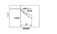
また、図13(特許文献1の図6に対応)に示すように、高回転、高トルク領域ではゲート信号の生成モードを1パルスの同期PWMモード(特許文献1では矩形波制御モード)に切り替える。ここで、高回転領域(図13の(a))ではモータの逆起電圧が高く、インバータの直流中間電圧を上回り、トルクの低下を生じやすい。そこで、切替ラインより上の範囲では1パルスの同期PWMモードを適用する。 Further, as shown in FIG. 13 (corresponding to FIG. 6 of Patent Document 1), the generation mode of the gate signal is switched to the 1-pulse synchronous PWM mode (rectangular wave control mode in Patent Document 1) in the high rotation and high torque regions. . Here, in the high rotation region ((a) of FIG. 13), the back electromotive force of the motor is high, exceeds the direct current intermediate voltage of the inverter, and torque is likely to decrease. Therefore, the 1-pulse synchronous PWM mode is applied in the range above the switching line.
ところで、インバータの損失だけを考えた場合、非同期PWMモードよりも同期PWMモードの方が有利である。何故ならば、同期PWMモードでは、インバータのスイッチング回数が少なく、たとえば1パルスの同期PWMモードの場合、電圧指令の1周期において、PWMパルスの電圧極性が正から負と負から正へ1回ずつしかスイッチングしない。従って、インバータのスイッチングロスを最小限にとどめることが可能である。 By the way, when only the inverter loss is considered, the synchronous PWM mode is more advantageous than the asynchronous PWM mode. This is because, in the synchronous PWM mode, the number of times the inverter is switched is small. For example, in the synchronous PWM mode of one pulse, the voltage polarity of the PWM pulse is once from positive to negative and from negative to positive once in one cycle of the voltage command. Only switching. Therefore, it is possible to minimize the switching loss of the inverter.
しかしながら、同期PWMモードでは、モータが無負荷の状態でもインバータからモータに電流が流れ、モータの損失が発生する。その一方、非同期PWMモードでは、モータが無負荷状態の場合、インバータからモータへ流れる電流はほとんどない。従って、可変速範囲が広く、かつ、全体として低損失のモータ駆動システムを実現するためには、特許文献1にも開示されているように、回転速度が閾値より低い領域では、非同期PWMモードでインバータに対するゲート信号を生成し、回転速度が閾値より高い領域では、同期PWMモードでインバータに対するゲート信号を生成するのが得策である。
However, in the synchronous PWM mode, a current flows from the inverter to the motor even when the motor is unloaded, and a motor loss occurs. On the other hand, in the asynchronous PWM mode, when the motor is in a no-load state, almost no current flows from the inverter to the motor. Therefore, in order to realize a motor drive system having a wide variable speed range and a low loss as a whole, as disclosed in
しかし、回転速度が閾値よりも高くても、インバータおよびモータの全体としての損失に鑑みると、同期PWMモードへ切り替えることが必ずしも得策でない場合がある。さらに詳述すると次の通りである。 However, even if the rotational speed is higher than the threshold value, it may not always be a good idea to switch to the synchronous PWM mode in view of the loss of the inverter and the motor as a whole. Further details are as follows.
まず、非同期PWMモードから同期PWMモードに切り替えた場合において、負のd軸電流が流れ、弱め界磁制御が働く場合(誘起電圧に比べてインバータの出力電圧が低い場合)には、トルク不足の問題が解消する。 First, when switching from the asynchronous PWM mode to the synchronous PWM mode, when a negative d-axis current flows and field weakening control works (when the output voltage of the inverter is lower than the induced voltage), there is a problem of insufficient torque. Eliminate.
しかし、正のd軸電流が流れる状況では、モータ内の磁束密度が高くなって、モータの損失(すなわち、トルクの発生に寄与しないインバータの出力)が増える。このようにモータが高速回転している領域において、同期PWMモードへの切り替えを行うと、インバータおよびモータの全体としての損失が増加する場合があるのである。 However, in a situation where a positive d-axis current flows, the magnetic flux density in the motor increases and the motor loss (that is, the output of the inverter that does not contribute to the generation of torque) increases. Thus, when switching to the synchronous PWM mode in the region where the motor is rotating at high speed, the loss of the inverter and the motor as a whole may increase.
この発明は、以上説明した事情に鑑みてなされたものであり、可変速度範囲が広く、かつ、低損失のモータ駆動システムを実現することができるインバータの制御装置を提供することを目的としている。 The present invention has been made in view of the circumstances described above, and an object of the present invention is to provide an inverter control device that can realize a motor drive system with a wide variable speed range and a low loss.
この発明は、モータを駆動するインバータを構成するスイッチング素子のON/OFF切替を行うためのゲート信号を生成する手段であって、前記ゲート信号の生成モードとして、前記インバータから前記モータに供給すべき交流電圧波形を指示する電圧指令とこの電圧指令に対して非同期な所定周波数のキャリアとを用いたパルス幅変調により前記ゲート信号を生成する非同期PWMモードと、前記電圧指令と前記電圧指令に同期したキャリアを用いたパルス幅変調により前記ゲート信号を生成する同期PWMモードとを有するゲート信号生成手段と、前記ゲート信号生成手段が前記同期PWMモードで前記インバータに与えるゲート信号を生成しているとき、前記インバータから前記モータに供給される電流のうち前記モータのロータに設けられた永久磁石のN極の向きに対応した成分であるd軸電流が正になったか否かを判定し、判定結果が肯定的である場合に前記ゲート信号生成手段のゲート信号の生成モードを前記非同期PWMモードに切り替える非同期/同期切替手段とを具備することを特徴とするインバータの制御装置を提供する。 The present invention is a means for generating a gate signal for switching ON / OFF of a switching element constituting an inverter that drives a motor, and should be supplied from the inverter to the motor as a generation mode of the gate signal. Asynchronous PWM mode for generating the gate signal by pulse width modulation using a voltage command indicating an AC voltage waveform and a carrier having a predetermined frequency asynchronous to the voltage command, and synchronized with the voltage command and the voltage command A gate signal generating means having a synchronous PWM mode for generating the gate signal by pulse width modulation using a carrier, and the gate signal generating means is generating a gate signal to be supplied to the inverter in the synchronous PWM mode, Of the current supplied from the inverter to the motor, the rotor of the motor It is determined whether or not the d-axis current, which is a component corresponding to the direction of the north pole of the permanent magnet, has become positive, and when the determination result is affirmative, the gate signal generation mode of the gate signal generation means And an asynchronous / synchronous switching means for switching to the asynchronous PWM mode.
この発明によれば、ゲート信号生成手段が同期PWMモードでインバータに与えるゲート信号を生成しているとき、インバータからモータに供給される電流のうちd軸電流が正になると、ゲート信号生成手段のゲート信号の生成モードを非同期PWMモードに切り替えられる。従って、弱め界磁が働かない状況において同期PWMモードが継続されるのを回避し、モータの損失が増大するのを回避することができる。 According to the present invention, when the gate signal generating means generates a gate signal to be supplied to the inverter in the synchronous PWM mode, if the d-axis current out of the current supplied from the inverter to the motor becomes positive, the gate signal generating means The generation mode of the gate signal can be switched to the asynchronous PWM mode. Therefore, it is possible to prevent the synchronous PWM mode from being continued in a situation where the field weakening does not work, and to avoid an increase in motor loss.
好ましい態様において、前記非同期/同期切替手段は、前記ゲート信号生成手段が前記非同期PWMモードで前記インバータに与えるゲート信号を生成しているとき、仮に前記ゲート信号生成手段におけるゲート信号の生成モードを前記同期PWMモードに切り替えた場合に、前記インバータから前記モータに供給されるd軸電流が0以下となるか否かを判定し、判定結果が肯定的である場合に前記ゲート信号生成手段のゲート信号の生成モードを前記同期PWMモードに切り替える。 In a preferred aspect, the asynchronous / synchronous switching means temporarily sets the generation mode of the gate signal in the gate signal generation means when the gate signal generation means generates a gate signal to be supplied to the inverter in the asynchronous PWM mode. When switching to the synchronous PWM mode, it is determined whether or not the d-axis current supplied from the inverter to the motor is 0 or less. If the determination result is affirmative, the gate signal of the gate signal generating means Is switched to the synchronous PWM mode.
この態様によれば、ゲート信号生成手段が非同期PWMモードでゲート信号を生成している期間、仮に同期PWMモードへの切り替えを行った場合に、弱め界磁が働き、モータの損失が増大しない場合に限り、同期PWMモードへの切り替えが行われる。従って、損失の増大を招くことなく、高速動作が可能なモータ駆動システムを実現することができる。 According to this aspect, when the switching to the synchronous PWM mode is performed during the period when the gate signal generating means is generating the gate signal in the asynchronous PWM mode, the field weakening works and the motor loss does not increase. Only in this case, switching to the synchronous PWM mode is performed. Therefore, it is possible to realize a motor drive system capable of high-speed operation without increasing loss.
他の好ましい態様において、前記非同期/同期切替手段は、前記ゲート信号生成手段が前記非同期PWMモードで前記インバータに与えるゲート信号を生成しているとき、仮に前記ゲート信号生成手段におけるゲート信号の生成モードを前記同期PWMモードに切り替えた場合に、前記インバータから前記モータに供給されるd軸電流が負の所定値以下になるか否かを判定し、判定結果が肯定的である場合に前記ゲート信号生成手段のゲート信号の生成モードを前記同期PWMモードに切り替える。 In another preferable aspect, the asynchronous / synchronous switching unit is configured to generate a gate signal generation mode in the gate signal generation unit when the gate signal generation unit generates a gate signal to be supplied to the inverter in the asynchronous PWM mode. Is switched to the synchronous PWM mode, it is determined whether or not the d-axis current supplied from the inverter to the motor is less than a predetermined negative value. If the determination result is affirmative, the gate signal The generation mode of the gate signal of the generation means is switched to the synchronous PWM mode.
この態様では、同期PWMモードから非同期PWMモードへの切り替えと非同期PWMモードから同期PWMモードへの切り替えとの間にヒステリシスが設けられている。従って、同期PWMモードおよび非同期PWMモード間の切り替えが頻繁に行われるのを防止し、モータ駆動システムの動作を安定化することができる。 In this aspect, hysteresis is provided between the switching from the synchronous PWM mode to the asynchronous PWM mode and the switching from the asynchronous PWM mode to the synchronous PWM mode. Therefore, frequent switching between the synchronous PWM mode and the asynchronous PWM mode can be prevented, and the operation of the motor drive system can be stabilized.
ゲート信号生成手段におけるゲート信号の生成モードを同期PWMモードに切り替えた場合にd軸電流が所定値以下となるか否かを判定するための手段に関しては、各種の態様が考えられる。好ましい態様において、制御装置は、前記インバータのスイッチング部に入力される直流中間電圧を検出する直流電圧検出手段と、前記直流電圧検出手段により検出される直流中間電圧に基づき、前記同期PWMモードにおける前記インバータの出力電圧を算出する出力電圧演算手段と、前記出力電圧演算手段により算出される前記インバータの出力電圧と、前記モータの回転速度とに基づき、前記モータにおいて発生する総合磁束を算出する総合磁束演算手段と、前記モータの基底周波数における逆起電圧と前記総合磁束演算手段により算出される総合磁束とに基づき、前記ゲート信号生成手段を同期PWMモードで動作させた場合において前記モータのd軸電流が所定値となる負荷角である切替負荷角を算出する切替負荷角演算手段と、現在のトルク指令に応じたトルクを同期PWMモードにおいて発生させるための負荷角を算出する負荷角演算手段と、前記負荷角演算手段により算出された負荷角と前記切替負荷角算出手段により算出された切替負荷角とを比較する負荷角比較手段とを具備し、前記非同期/同期切替手段は、前記負荷角比較手段の比較結果に基づき、前記非同期PWMモードから前記同期PWMモードへの切り替えを行うか否かを判定する。 Various modes can be considered for the means for determining whether or not the d-axis current is equal to or lower than a predetermined value when the gate signal generation mode in the gate signal generation means is switched to the synchronous PWM mode. In a preferred aspect, the control device is configured to detect the DC intermediate voltage input to the switching unit of the inverter, and based on the DC intermediate voltage detected by the DC voltage detecting means, the control PWM device in the synchronous PWM mode. Total voltage for calculating the total magnetic flux generated in the motor based on the output voltage calculation means for calculating the output voltage of the inverter, the output voltage of the inverter calculated by the output voltage calculation means, and the rotation speed of the motor The d-axis current of the motor when the gate signal generating means is operated in the synchronous PWM mode based on the calculating means, the back electromotive voltage at the base frequency of the motor and the total magnetic flux calculated by the total magnetic flux calculating means. Switching load angle calculating means for calculating a switching load angle that is a load angle at which becomes a predetermined value; A load angle calculating means for calculating a load angle for generating torque according to the current torque command in the synchronous PWM mode, a load angle calculated by the load angle calculating means, and a switching load angle calculating means Whether the asynchronous / synchronous switching means performs switching from the asynchronous PWM mode to the synchronous PWM mode based on the comparison result of the load angle comparing means. Determine whether or not.
他の好ましい態様では、直流中間電圧を検出するのでなく、予め直流電圧記憶手段に記憶させる。 In another preferred embodiment, the DC intermediate voltage is not detected but stored in advance in the DC voltage storage means.
切替負荷角は、その都度演算するのではなく、予めモータの回転速度を各種想定して演算したものをテーブルとして記憶しておき、このテーブルを参照するようにしてもよい。 The switching load angle may not be calculated each time, but may be stored in advance as a table calculated by assuming various rotation speeds of the motor, and this table may be referred to.
多くのインバータの制御装置は、プロセッサとこのプロセッサに実行させるプログラムを記憶したメモリとにより構成されている。従って、各種のモータを想定して、コンピュータを上記制御装置として機能させるプログラムを作成し、このプログラムをインバータの制御装置のユーザに配布するようにしてもよい。 Many inverter control devices include a processor and a memory that stores a program to be executed by the processor. Therefore, assuming various motors, a program for causing a computer to function as the control device may be created and distributed to users of inverter control devices.
以下、図面を参照し、この発明の実施形態について説明する。 Embodiments of the present invention will be described below with reference to the drawings.
<第1実施形態(基本形態)>
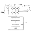
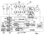
図1はこの発明の第1実施形態である制御装置を含むモータ駆動システムの構成を示すブロック図である。このモータ駆動システムは、インバータ10と、モータ20と、本実施形態による制御装置100とにより構成されている。この例においてモータ20は、永久磁石同期モータである。インバータ10は、このモータ20を駆動する交流電力を発生する装置であり、直流電源11と、この直流電源11により充電されるコンデンサ12と、コンデンサ12の充電電圧であるインバータ直流中間電圧を3相交流電圧に変換するスイッチング部13とにより構成されている。周知のインバータと同様、インバータ10のスイッチング部13は、IGBT(Insulated Gate Bipolar Transistor;絶縁ゲートバイポーラトランジスタ)およびフライホイールダイオードの組を6組用いて構成されたブリッジ回路である。
<First embodiment (basic form)>
FIG. 1 is a block diagram showing a configuration of a motor drive system including a control device according to a first embodiment of the present invention. This motor drive system includes an
制御装置100は、ゲート信号生成部101と、非同期/同期切替部102とを有する。ゲート信号生成部101は、スイッチング部13の各IGBTのON/OFF切替を行うためのゲート信号を発生する装置である。周知のインバータと同様、この制御装置100のゲート信号生成部101は、モータ20に供給すべき交流電圧波形を指示する電圧指令とキャリアとを用いてパルス幅変調を行い、このパルス幅変調により得られるPWMパルスをゲート信号としてスイッチング部13の各IGBTに供給する。
The
ゲート信号生成部101は、ゲート信号の生成モードとして、非同期PWMモードと1パルスの同期PWMモードとを有する。上述したように、非同期PWMモードは、電圧指令とこの電圧指令に対して非同期な所定周波数のキャリアとを用いたパルス幅変調によりPWMパルスを生成し、ゲート信号として出力する生成モードである。また、同期PWMモードは、電圧指令とこの電圧指令に同期したキャリアとを用いたパルス幅変調によりPWMパルスを生成し、ゲート信号として出力する生成モードである。以下、これらの各モードにおけるゲート信号生成部101の動作の概略について説明する。
The gate
まず、非同期PWMモードについて説明する。永久磁石同期モータであるモータ20のロータに発生するトルクTは式(1)により与えられる。

この式(1)において、Pnは極対数、Ψmはロータの永久磁石によって発生され、固定子巻線と鎖交する磁束、idはd軸電流、iqはq軸電流、Ldはd軸インダクタンス、Lqはq軸インダクタンスである。また、式(1)において、第1項は永久磁石の作る磁束により発生するトルク、第2項はリラクタンストルクである。 In this equation (1), P n is the number of pole pairs, Ψ m is a magnetic flux generated by a permanent magnet of the rotor and interlinks with the stator winding, i d is a d-axis current, i q is a q-axis current, L d Is a d-axis inductance, and L q is a q-axis inductance. In the formula (1), the first term is torque generated by the magnetic flux generated by the permanent magnet, and the second term is reluctance torque.
非同期PWMモードにおいて、ゲート信号生成部101は、所望のトルクが得られる電流がインバータ10からモータ20に供給されるようにインバータ10に与えるゲート信号を制御する。その際、モータ20の端子電圧に対してインバータ10の出力電圧に余裕がある場合には電流値が最小となるようにd軸電流idおよびq軸電流iqを制御し、モータ20の端子電圧に対してインバータ10の出力電圧が低い場合には、弱め界磁制御を行う。
In the asynchronous PWM mode, the gate
次に同期PWMモードについて説明する。ここでは、一例として1パルスの同期PWMモードについて説明する。 Next, the synchronous PWM mode will be described. Here, a one-pulse synchronous PWM mode will be described as an example.
定常状態において、モータ20の固定子巻線に与えられる交流電圧をd軸方向の成分であるd軸電圧vdとq軸方向の成分であるq軸電圧vqに分解すると、これらのd軸電圧vdおよびq軸電圧vqは式(2)および式(3)により与えられる。
また、モータ20の端子電圧vmtとd軸電圧vdおよびq軸電圧vqとの関係は次式に示すものとなる。
ここで、巻線抵抗が十分に小さい(Ra≒0)と仮定し、vd=−Va・sinδ、vq=Va・cosδを式(2)、式(3)に代入し、式(2)、式(3)をid、iqについて解いて、式(1)に代入すると、式(5)が得られる。ただし、Vaはインバータ出力電圧、δは負荷角、すなわち、モータ20内に発生する総合磁束Ψ0の向きとロータの永久磁石の磁束Ψmの向きとがなす角度である。
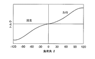
1パルスの同期PWMモードにおいて、ゲート信号生成部101は、電圧指令と同じ周波数を有する一定の電圧Vaをインバータ10に出力させる。コンデンサ12に充電されるインバータ直流電圧をedcとすると、このインバータ10の出力電圧Vaは、式(6)により与えられる。
1パルスの同期PWMモードでは、上記式(5)における電圧Vaが一定となるため、モータ20に発生するトルクTは負荷角δに依存する。図2は、式(5)における負荷角δとトルクの関係を示すものである。負荷角δが正の領域は、モータ20において力行(モータとしての動作)が行われている領域である。負荷角δが負の領域は、モータ20において回生(発電機としての動作)が行われている領域である。
以上が非同期PWMモードおよび1パルスの同期PWMモードの動作の概略である。
In the 1-pulse synchronous PWM mode, the voltage Va in the above equation (5) is constant, so the torque T generated in the
The above is the outline of the operations in the asynchronous PWM mode and the one-pulse synchronous PWM mode.
非同期/同期切替部102は、ゲート信号生成部101のゲート信号の生成モードを非同期PWMモードとするか同期PWMモードとするかの切替制御を行う装置である。本実施形態の特徴はこの非同期/同期切替部102にある。
The asynchronous /
従来技術の下では、モータ20の回転速度に基づき、ゲート信号の生成モードを非同期PWMモードとするか同期PWMモードとするかの切替制御を行った。しかし、このような回転速度のみに基づく画一的な切替制御を行うと、高速回転領域において同期PWMモードへの切り替えを行った場合にインバータ10およびモータ20の全体としての損失が増える場合がある。そこで、本実施形態における非同期/同期切替部102は、弱め界磁制御が働き、かつ、インバータ10およびモータ20の全体としての損失が増加する不利益が生じないことを条件にゲート信号生成部101を同期PWMモードで動作させる。以下、非同期/同期切替部102により行われる非同期PWMモードおよび同期PWMモード間の切替制御の原理について説明する。
Under the prior art, based on the rotational speed of the
インバータ10およびモータ20に発生する損失は、インバータ10からモータ20に供給される電流に依存する。そこで、まず、モータ20の固定子巻線に発生する逆起電圧がコンデンサ12に充電された直流中間電圧edcよりも低い状態において、1パルスの同期PWMモードでのゲート信号の生成を行った場合にモータ20の固定子巻線に流れる電流について検討する。
The loss generated in the
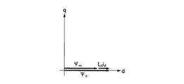
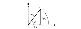
図3は負荷ゼロ、すなわち、負荷角δ=0におけるモータ20内の磁束のベクトル図を示す。ここで、モータ20内において発生する総合磁束Ψ0は、式(7)により求めることができる。
図3から分かるように、無負荷であってもインバータ10の出力電圧Vaが一定の条件の下ではd軸電流idがモータ20に流れる。さらにd軸電流idは正であるので、このd軸電流idはモータ20内の磁束を強める。ここで、非同期PWMモードでは、トルクがゼロならばインバータ10からモータ20にほとんど電流が供給されないので、インバータ10でのロスはほとんど発生しない。しかし、同期PWMモードでは、インバータ10の出力電圧Vaを一定にするので、図3に示すように、モータ20の負荷がゼロでもインバータ10からモータ20にd軸電流idが流れるためインバータ10にてロスが発生する。また、モータ20に着目すると、無負荷であってもd軸電流idが流れればモータ20の固定子巻線に銅損が発生する。そして、強め磁束方向にd軸電流idが流れると(すなわち、正のd軸電流idが流れると)、モータ20の鉄心の磁束密度が高まるため、鉄損が増加するといった問題が発生する。
As seen from FIG. 3, d-axis current i d under the output voltage Va is constant conditions of the
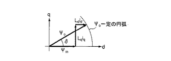
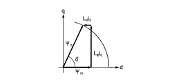
図4に、軽負荷におけるモータ20内の磁束のベクトル図を示す。負荷角δが大きくなるとq軸電流iqが流れ始める。しかし、d軸電流idは正のまま推移する。モータ20の鉄損に着目すると、やはり強め磁束方向にd軸電流idが流れるため鉄損が増加する。
FIG. 4 shows a vector diagram of magnetic flux in the
負荷が増加してゆき、負荷角δが大きくなると、図5に示すようにid=0となり、さらに負荷が増加すると図6に示すようにd軸電流idは負となる。このように同期PWMモードにおいて、モータ20に流れるd軸電流idが0または負になる領域では、モータ20内の鉄損の増加は生じない。また、d軸電流idが負である場合、モータ20内の磁束が弱められ、モータ20の固定子巻線に誘起される逆起電圧が減るので、q軸電流iqを増加させ、モータ20に発生するトルクを高めることができる。
Load Yuki increases, the load angle δ increases, d-axis current i d, as shown in FIG. 6 the
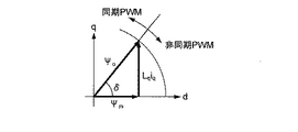
そこで、本実施形態における非同期/同期切替部102は、ゲート信号生成部101が同期PWMモードにてゲート信号を生成している期間、モータ20に流れるd軸電流idが正になったか否かの判定を行い、判定結果が肯定的である場合にゲート信号生成部101のゲート信号の生成モードを非同期PWMモードに切り替える。また、非同期/同期切替部102は、ゲート信号生成部101が非同期PWMモードにてゲート信号を生成している期間、仮に同期PWMモードへの切り替えを行った場合にモータ20に流れるd軸電流idが0または負になるか否かの判定を行い、判定結果が肯定的である場合にゲート信号生成部101のゲート信号の生成モードを同期PWMモードに切り替える。すなわち、本実施形態では、図7に示すように、インバータ10の出力電圧Vaを一定にした場合においてd軸電流idが0または負となる領域においては同期PWMモードを採用し、それ以外の領域においては非同期PWMモードを採用する。
Therefore, asynchronous /
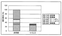
図8は、モータ20の逆起電圧がインバータ10の直流中間電圧edcよりも低い場合におけるインバータ10の損失解析結果を示す。ただし、非同期PWMモードでは電流位相40度にて弱め磁束制御を施し、1パルスの同期PWMモードでは図5に示すid=0となる条件とした。図8より、非同期PWMモードに対し、1パルスの同期PWMモードでは、IGBTのターンオンやターンオフ損失、さらにフライホイールダイオードFWDの逆回復損失が大幅に低下しており、インバータ10全体の損失が約6.5割低下した。以上のように、本実施形態によれば、ゲート信号生成部101が同期PWMモードでインバータ20に与えるゲート信号を生成しているとき、インバータ10からモータ20に供給される電流のうちd軸電流が正になると、ゲート信号生成部101のゲート信号の生成モードを非同期PWMモードに切り替えられるので、弱め界磁が働かない状況において同期PWMモードが継続されるのを回避し、モータの損失が増大するのを回避することができる。また、本実施形態によれば、ゲート信号生成部101が非同期PWMモードでゲート信号を生成している期間、仮に同期PWMモードへの切り替えを行った場合に、弱め界磁が働き、モータの損失が増大しない場合に限り、同期PWMモードへの切り替えが行われる。従って、損失の増大を招くことなく、高速動作が可能なモータ駆動システムを実現することができる。
FIG. 8 shows a loss analysis result of the
<第2実施形態>
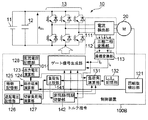
図9はこの発明の第2実施形態である制御装置100Aを含むモータ駆動システムの構成を示すブロック図である。インバータ10およびモータ20の構成は上記第1実施形態(図1)と同様である。以下、制御装置100Aの構成を説明する。
Second Embodiment
FIG. 9 is a block diagram showing a configuration of a motor drive system including a
電流検出部111は、インバータ10からモータ20のU相、V相およびW相の各固定子巻線に各々供給されるU相電流iu、V相電流ivおよびW相電流iwを検出する手段である。三相二相変換部112は、電流検出部111により検出されたU相電流iu、V相電流ivおよびW相電流iwをα軸およびβ軸からなる所定の静止直交座標系における2相の電流iαおよびiβに変換する手段である。この2相の電流iαおよびiβは、静止直交座標系において回転する電流ベクトルのα軸成分およびβ軸成分である。そして、座標変換部113は、電流iαおよびiβを、モータ20のロータに設けられたN極の方向を向いたd軸と、このd軸に直交するq軸とからなる回転直交座標系のd軸電流idおよびq軸電流iqに座標変換する手段である。なお、三相二相変換部112や座標変換部113は、周知の技術であるため、詳細な説明は省略するが、例えば非特許文献1において説明されている。
Current detecting
回転数検出部121は、モータ20のロータの回転速度nを検出する。直流電圧検出部122は、コンデンサ12に充電された直流中間電圧edcを検出し、出力電圧演算部123へ検出した電圧値edcを出力する。出力電圧演算部123は、前掲式(6)に従い、同期PWMモードにおける出力電圧Vaを演算し、総合磁束演算部124へ出力する。総合磁束演算部124は、次のように総合磁束Ψ0の演算を行う。まず、総合磁束演算部124は、式(8)に従い、モータ20の回転速度に対応した電気角速度ωを算出する。
次に総合磁束演算部は、電気角速度ωと出力電圧演算部123により算出された出力電圧Vaとに基づき、前掲式(7)に従い、総合磁束Ψ0を算出する。 Next, the total magnetic flux calculation unit calculates the total magnetic flux Ψ 0 according to the above equation (7) based on the electrical angular velocity ω and the output voltage Va calculated by the output voltage calculation unit 123.
逆起電圧記憶部126は、基底周波数fbaseと基底周波数におけるモータ20の逆起電圧vemfを記憶している。ここで、基底周波数fbaseは、モータ20が最大トルクを低下させることなく動作可能なモータ20の回転速度の最大値をモータ20の逆起電圧の周波数に換算したものである。切替負荷角演算部127は、d軸電流idが0となる負荷角δである切替負荷角δ1を算出する手段である。この切替負荷角演算部127は、まず、逆起電圧記憶部126に記憶された基底周波数fbaseと逆起電圧vemfとに基づき、式(9)に従い、磁石磁束Ψmを算出する。
次に切替負荷角演算部127は、総合磁束Ψ0と磁石磁束Ψmとに基づき、式(10)に従って切替負荷角δ1を演算する(図7参照)。
負荷角演算部131は、仮に同期PWMモードに切り替えた場合に、現在のトルク指令に応じたトルクTを発生させるのに必要な負荷角δを前掲式(5)から逆算する。その際に、総合磁束演算部124により算出された総合磁束Ψ0と、Ld,Lq記憶部132に予め記憶されたd軸インダクタンスLdおよびq軸インダクタンスLqを用いる。
When the load
負荷角比較部141は、負荷角δとd軸電流idがゼロとなる切替負荷角δ1を比較し、δ<δ1ならばモードフラグFLGを“0”に、δ≧δ1ならばモードフラグFLGを“1”に設定する。
The load
非同期/同期切替部142は、ゲート信号生成部101が非同期PWMモードでゲート信号を生成している期間にモードフラグFLGが“1”になったとき、ゲート信号生成部101のゲート信号の生成モードを同期PWMモードに切り替え、モードフラグFLGが“0”の場合は非同期PWMモードを維持させる。また、非同期/同期切替部142は、ゲート信号生成部101が同期PWMモードでゲート信号を生成している期間内に、座標変換部113により算出されるd軸電流idが正になった場合、ゲート信号生成部101のゲート信号の生成モードを非同期PWMモードに切り替える。
The asynchronous / synchronous switching unit 142 is configured to generate a gate signal generation mode of the gate
本実施形態によれば、上記第1実施形態と同様な効果が得られる。また、本実施形態では、非同期PWMモードでの制御と並行し、同期PWMモードへ切り替えた場合の負荷角δの算出が進められるので、制御装置100Aでは、負荷角δが切替負荷角δ1に接近する状況を把握することができる。従って、δ≧δ1となって非同期PWMモードから同期PWMモードへ切り替えるとき、その切り替えのための制御を円滑に進めることができる。
According to this embodiment, the same effect as the first embodiment can be obtained. In the present embodiment, since the calculation of the load angle δ when switching to the synchronous PWM mode is advanced in parallel with the control in the asynchronous PWM mode, the load angle δ is changed to the switching load angle δ 1 in the
<第3実施形態>
図10はこの発明の第3実施形態である制御装置100Bを含むモータ駆動システムの構成を示すブロック図である。インバータ10およびモータ20の構成は上記第1実施形態(図1)と同様である。本実施形態における制御装置100Bでは、上記第2実施形態(図9)における直流電圧検出部122が直流電圧記憶部128に置き換えられている。この直流電圧記憶部128は、コンデンサ12に充電されるインバータ直流中間電圧edcを予め記憶する手段である。インバータ直流中間電圧edcの値がほとんど変動しない場合、直流電圧記憶部128に予め記憶しておいたインバータ直流中間電圧edcを用いて、非同期PWMモードから同期PWMモードへの切替制御を行ってもよい。この切替制御の内容は上記第2実施形態と同様なので説明を省略する。
<Third Embodiment>
FIG. 10 is a block diagram showing a configuration of a motor drive system including a
<第4実施形態>
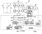
図11はこの発明の第4実施形態である制御装置100Cを含むモータ駆動システムの構成を示すブロック図である。インバータ10およびモータ20の構成は上記第1実施形態(図1)と同様である。
<Fourth embodiment>
FIG. 11 is a block diagram showing a configuration of a motor drive system including a
制御装置100Cにおいて、ゲート信号生成部101、電流検出部111、三相二相変換部112、座標変換部113、回転数検出部121、Ld,Lq記憶部132は、上記第2実施形態(図9)と同様である。
In the
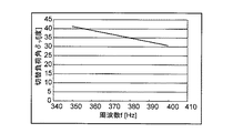
切替負荷角記憶部129は、モータ20に発生する逆起電圧の周波数fを切替負荷角δ1に対応付けるテーブルを記憶している。以下、具体的なモータ20の仕様を挙げて、この切替負荷角δ1のテーブルの作成方法を説明する。一例として、モータ20の周波数400Hzにおける逆起電圧の実効値が380V、q軸インダクタンスLqが2.2mHであるとする。また、インバータ直流中間電圧edcは565.7Vであるとする。また、モータ20の基底周波数fbaseは400Hz、基底周波数におけるモータ20の逆起電圧vemfが380Vであるとする。この場合、式(9)にfbase=400Hz、vemf=380Vを代入することにより、磁石磁束Ψmは0.151Wbとなる。
The switching load
インバータ出力電圧Vaは、式(6)にedc=565.7Vを代入すると、Va=441.1Vとなる。この場合、周波数fにおける切替負荷角δ1は(式16)のように求まる。
上記式(11)にΨm、Vaと、350Hz〜400Hzまでの周波数fを代入すると、周波数f=350Hz〜400Hzにおける切替負荷角δ1が得られる。図12はその結果を示すものである。切替負荷角記憶部129には、このようにして求められた切替負荷角δ1のテーブルが記憶されている。
Substituting ψ m , Va and the frequency f from 350 Hz to 400 Hz into the above equation (11), the switching load angle δ 1 at the frequency f = 350 Hz to 400 Hz is obtained. FIG. 12 shows the result. The switching load
負荷角演算部133は、仮に同期PWMモードに切り替えた場合に、現在のトルク指令に応じたトルクTを発生させるのに必要な負荷角δを前掲式(5)から逆算する。その際に、負荷角演算部133は、回転数検出部121により検出される回転速度nからモータ20の誘起電圧の周波数f=nP/120を求め、この周波数fにより定まる総合磁束Ψ0=Va/fと、Ld,Lq記憶部132に予め記憶されたd軸インダクタンスLdおよびq軸インダクタンスLqを用いることによりトルクTに対応した負荷角δを求める。
When the load
負荷角比較部143は、モータ20の誘起電圧の周波数fに対応した切替負荷角δ1を切替負荷角記憶部129内のテーブルから読み出し、この読み出した切替負荷角δ1と負荷角演算部133により算出された負荷角δとを比較する。そして、δ<δ1ならばモードフラグFLGを“0”に、δ≧δ1ならばモードフラグFLGを“1”に設定する。
The load
非同期/同期切替部142の機能は上記第2実施形態と同様である。本実施形態においても上記第2実施形態と同様な効果が得られる。また、本実施形態によれば、切替負荷角δ1の演算処理がテーブル参照処理に置き換えられているので、上記第2実施形態に比べた制御装置100Cの演算の負担が少ないという利点がある。
The function of the asynchronous / synchronous switching unit 142 is the same as that of the second embodiment. Also in this embodiment, the same effect as the second embodiment can be obtained. Further, according to the present embodiment, since the calculation process of the switching load angle δ1 is replaced with the table reference process, there is an advantage that the calculation load of the
<他の実施形態>
以上、この発明の第1〜第4実施形態を説明したが、この発明には他にも実施形態が考えられる。例えば次の通りである。
<Other embodiments>
Although the first to fourth embodiments of the present invention have been described above, other embodiments are conceivable for the present invention. For example:
(1)インバータの電源は、図示のように直流電源でも良く、交流をダイオード整流器等で直流に変換して得ても良い。 (1) The power source of the inverter may be a DC power source as shown, or may be obtained by converting AC to DC with a diode rectifier or the like.
(2)ゲート信号生成部にはトルク指令を入力として与えているが、速度指令を与え、速度指令値と実際の速度との偏差からトルク指令を得る方式でも良い。 (2) Although a torque command is given as an input to the gate signal generation unit, a method may be used in which a speed command is given and the torque command is obtained from the deviation between the speed command value and the actual speed.
(3)電流検出部は必ずしも三相電流を検出する必要はなく、二相を検出し、残りの一相は演算で求めても良い。 (3) The current detector does not necessarily need to detect a three-phase current, but may detect two phases and obtain the remaining one phase by calculation.
(4)回転数検出部を設ける代わりに回転数予測部を設けても良い。 (4) Instead of providing the rotation speed detection unit, a rotation speed prediction unit may be provided.
(5)同期PWMモードから非同期PWMモードへの移行はd軸電流idがゼロとなる負荷角δ1にて切替え、逆に非同期PWMモードから同期PWMモードへの移行はd軸電流idが負となる負荷角δ1+Δδ(たとえばΔδ=5度)から開始するようにしてもよい。この場合、同期PWMモードから非同期PWMモードへの切り替えと非同期PWMモードから同期PWMモードへの切り替えとの間にヒステリシスが設けられている。従って、同期PWMモードおよび非同期PWMモード間の切り替えが頻繁に行われるのを防止し、モータ駆動システムの動作を安定化することができる。 (5) synchronous transition from PWM mode to the asynchronous PWM mode switching at a load angle [delta] 1 of d-axis current i d is zero, the transition from the asynchronous PWM mode to the synchronous PWM mode conversely d-axis current id negative The load angle δ 1 + Δδ (for example, Δδ = 5 degrees) may be started. In this case, hysteresis is provided between the switching from the synchronous PWM mode to the asynchronous PWM mode and the switching from the asynchronous PWM mode to the synchronous PWM mode. Therefore, frequent switching between the synchronous PWM mode and the asynchronous PWM mode can be prevented, and the operation of the motor drive system can be stabilized.
(6)上記各実施形態では、同期PWMモードとして1パルスの同期PWMモードを採用したが、インバータ出力電圧一定の下で負荷角を制御してトルク制御を実施する場合、3パルス等の同期PWMモードにも適用可能である。 (6) In each of the above embodiments, the single-pulse synchronous PWM mode is adopted as the synchronous PWM mode. However, when the torque control is performed by controlling the load angle under a constant inverter output voltage, the synchronous PWM such as three pulses is used. Applicable to modes.
(7)上記第4実施形態では、モータ20の回転速度nに比例する逆起電圧の周波数fを切替負荷角δ1に対応付ける切替負荷角テーブルを切替負荷角記憶部129に記憶させた。しかし、そのようにする代わりに、モータ20の回転速度nに比例する他のパラメータまたはモータ20の回転速度n自体を切替負荷角δ1に対応付ける切替負荷角テーブルを切替負荷角記憶部129に記憶させ、この切替負荷角テーブルを参照することにより現在の回転速度nに対応した切替負荷角δ1を求めるようにしてもよい。
(7) In the fourth embodiment, the switching load
(7)上記各実施形態において、非同期/同期切替部は、次の2つの切替制御を行った。
切替制御A:ゲート信号生成部が同期PWMモードでゲート信号を生成しているとき、d軸電流が正になったか否かを判定し、判定結果が肯定的である場合にゲート信号生成部のゲート信号の生成モードを非同期PWMモードに切り替える。
切替制御B:ゲート信号生成部が非同期PWMモードでゲート信号を生成しているとき、仮にゲート信号の生成モードを同期PWMモードに切り替えた場合に、d軸電流が0以下となるか否かを判定し、判定結果が肯定的である場合にゲート信号の生成モードを同期PWMモードに切り替える。
しかし、切替制御Bについては、例えばモータの回転速度が閾値を越えた場合に同期PWMモードへの切り替えを行う等、他の方法により同期PWMモードへの切り替えを行うようにしてもよい。その結果、同期PWMモードにおいてd軸電流が正になった場合は、切替制御Aが働くので、インバータおよびモータの全体としての損失の増加を防止することができる。
(7) In each of the above embodiments, the asynchronous / synchronous switching unit performs the following two switching controls.
Switching control A: When the gate signal generation unit is generating a gate signal in the synchronous PWM mode, it is determined whether or not the d-axis current is positive, and if the determination result is affirmative, the gate signal generation unit The generation mode of the gate signal is switched to the asynchronous PWM mode.
Switching control B: Whether or not the d-axis current becomes 0 or less when the gate signal generation unit generates the gate signal in the asynchronous PWM mode and the gate signal generation mode is switched to the synchronous PWM mode. When the determination result is affirmative, the gate signal generation mode is switched to the synchronous PWM mode.
However, for the switching control B, for example, switching to the synchronous PWM mode may be performed by another method such as switching to the synchronous PWM mode when the rotational speed of the motor exceeds a threshold value. As a result, when the d-axis current becomes positive in the synchronous PWM mode, the switching control A works, so that it is possible to prevent the loss of the inverter and the motor as a whole.
(8)多くのインバータの制御装置は、プロセッサとこのプロセッサに実行させるプログラムを記憶したメモリとにより構成されている。そこで、各種のモータを想定して、コンピュータを本発明による制御装置として機能させるプログラムを作成し、このプログラムをインバータの制御装置のユーザに配布するようにしてもよい。例えば上記第2実施形態(図9)において、ゲート信号生成部101、三相二相変換部112、座標変換部113、出力電圧演算部123、総合磁束演算部124、切替負荷角演算部127、負荷角比較部141および非同期/同期切替部142の実体は、プロセッサがプログラムに従って実行する演算処理である。そこで、各種のモータ20を想定してこのプログラムを作成し、制御装置のメモリにインストールするのである。その際、Ld,Lq記憶部132等の各種の記憶部に記憶させるパラメータは、プログラム自体に持たせてもよく、あるいは不揮発性メモリ等に記憶させたものをプログラムに読み込ませるようにしてもよい。上記第2実施形態以外の各実施形態をプログラムとして実現する場合も同様である。
(8) Many inverter control devices include a processor and a memory that stores a program to be executed by the processor. Therefore, assuming various motors, a program for causing a computer to function as a control device according to the present invention may be created, and this program may be distributed to users of inverter control devices. For example, in the second embodiment (FIG. 9), the gate
10……インバータ、20……モータ、100,100A,100B,100C……制御装置、101……ゲート信号生成部、102,142……非同期/同期切替部、111……電流検出部、112……三相二相変換部、113……座標変換部、132……Ld,Lq記憶部、131……負荷角演算部、121……回転数検出部、122……直流電圧検出部、123……出力電圧演算部、124……総合磁束演算部、125……極数記憶部、126……逆起電圧記憶部、127……切替負荷角演算部、128……直流電圧記憶部、141,143……負荷角比較部、129……切替負荷角記憶部。
DESCRIPTION OF
Claims (8)
前記ゲート信号生成手段が前記同期PWMモードで前記インバータに与えるゲート信号を生成しているとき、前記インバータから前記モータに供給される電流のうち前記モータのロータに設けられた永久磁石のN極の向きに対応した成分であるd軸電流が正になったか否かを判定し、判定結果が肯定的である場合に前記ゲート信号生成手段のゲート信号の生成モードを前記非同期PWMモードに切り替える非同期/同期切替手段と
を具備することを特徴とするインバータの制御装置。 A means for generating a gate signal for ON / OFF switching of a switching element constituting an inverter that drives a motor, wherein an AC voltage waveform to be supplied from the inverter to the motor is generated as the generation mode of the gate signal. Asynchronous PWM mode in which the gate signal is generated by pulse width modulation using a voltage command to be instructed and a carrier having a predetermined frequency asynchronous to the voltage command, and a carrier synchronized with the voltage command and the voltage command is used. A gate signal generating means having a synchronous PWM mode for generating the gate signal by pulse width modulation;
When the gate signal generating means generates a gate signal to be supplied to the inverter in the synchronous PWM mode, out of the current supplied from the inverter to the motor, the N pole of the permanent magnet provided in the rotor of the motor It is determined whether or not the d-axis current, which is a component corresponding to the direction, has become positive, and when the determination result is affirmative, the gate signal generation mode of the gate signal generation unit is switched to the asynchronous PWM mode. And an inverter control device.
前記直流電圧検出手段により検出される直流中間電圧に基づき、前記同期PWMモードにおける前記インバータの出力電圧を算出する出力電圧演算手段と、
前記出力電圧演算手段により算出される前記インバータの出力電圧と、前記モータの回転速度とに基づき、前記モータにおいて発生する総合磁束を算出する総合磁束演算手段と、
前記モータの基底周波数における逆起電圧と前記総合磁束演算手段により算出される総合磁束とに基づき、前記ゲート信号生成手段を前記同期PWMモードで動作させた場合において前記モータのd軸電流が所定値となる負荷角である切替負荷角を算出する切替負荷角演算手段と、
現在のトルク指令に応じたトルクを前記同期PWMモードにおいて発生させるための負荷角を算出する負荷角演算手段と、
前記負荷角演算手段により算出された負荷角と前記切替負荷角算出手段により算出された切替負荷角とを比較する負荷角比較手段とを具備し、
前記非同期/同期切替手段は、前記負荷角比較手段の比較結果に基づき、前記非同期PWMモードから前記同期PWMモードへの切り替えを行うか否かを判定することを特徴とする請求項2または3に記載の制御装置。 DC voltage detecting means for detecting a DC intermediate voltage input to the switching unit of the inverter;
Output voltage calculation means for calculating the output voltage of the inverter in the synchronous PWM mode based on the DC intermediate voltage detected by the DC voltage detection means;
Based on the output voltage of the inverter calculated by the output voltage calculation means and the rotational speed of the motor, total magnetic flux calculation means for calculating the total magnetic flux generated in the motor;
Based on the back electromotive voltage at the base frequency of the motor and the total magnetic flux calculated by the total magnetic flux calculating means, the d-axis current of the motor is a predetermined value when the gate signal generating means is operated in the synchronous PWM mode. A switching load angle calculating means for calculating a switching load angle that is a load angle of
A load angle calculation means for calculating a load angle for generating torque in accordance with the current torque command in the synchronous PWM mode;
Load angle comparison means for comparing the load angle calculated by the load angle calculation means and the switching load angle calculated by the switching load angle calculation means,
4. The asynchronous / synchronous switching unit determines whether or not to switch from the asynchronous PWM mode to the synchronous PWM mode based on a comparison result of the load angle comparing unit. The control device described.
前記直流電圧記憶手段に記憶された直流中間電圧に基づき、前記同期PWMモードにおける前記インバータの出力電圧を算出する出力電圧演算手段と、
前記出力電圧演算手段により算出される前記インバータの出力電圧と、前記モータの回転速度とに基づき、前記モータにおいて発生する総合磁束を算出する総合磁束演算手段と、
前記モータの基底周波数における逆起電圧と前記総合磁束演算手段により算出される総合磁束とに基づき、前記ゲート信号生成手段を前記同期PWMモードで動作させた場合において前記モータのd軸電流が所定値となる負荷角である切替負荷角を算出する切替負荷角演算手段と、
現在のトルク指令に応じたトルクを前記同期PWMモードにおいて発生させるための負荷角を算出する負荷角演算手段と、
前記負荷角演算手段により算出された負荷角と前記切替負荷角算出手段により算出された切替負荷角とを比較する負荷角比較手段とを具備し、
前記非同期/同期切替手段は、前記負荷角比較手段の比較結果に基づき、前記非同期PWMモードから前記同期PWMモードへの切り替えを行うか否かを判定することを特徴とする請求項2または3に記載の制御装置。 DC voltage storage means for storing a DC intermediate voltage input to the switching unit of the inverter;
An output voltage calculation means for calculating an output voltage of the inverter in the synchronous PWM mode based on a DC intermediate voltage stored in the DC voltage storage means;
Based on the output voltage of the inverter calculated by the output voltage calculation means and the rotational speed of the motor, total magnetic flux calculation means for calculating the total magnetic flux generated in the motor;
Based on the back electromotive voltage at the base frequency of the motor and the total magnetic flux calculated by the total magnetic flux calculating means, the d-axis current of the motor is a predetermined value when the gate signal generating means is operated in the synchronous PWM mode. A switching load angle calculating means for calculating a switching load angle that is a load angle of
A load angle calculation means for calculating a load angle for generating torque in accordance with the current torque command in the synchronous PWM mode;
Load angle comparison means for comparing the load angle calculated by the load angle calculation means and the switching load angle calculated by the switching load angle calculation means,
4. The asynchronous / synchronous switching unit determines whether or not to switch from the asynchronous PWM mode to the synchronous PWM mode based on a comparison result of the load angle comparing unit. The control device described.
現在のトルク指令に応じたトルクを前記同期PWMモードにおいて発生させるための負荷角を算出する負荷角演算手段と、
前記負荷角演算手段により算出された負荷角と前記切替負荷角記憶手段に記憶された現在のモータの回転速度に対応した切替負荷角とを比較する負荷角比較手段とを具備し、
前記非同期/同期切替手段は、前記負荷角比較手段の比較結果に基づき、前記非同期PWMモードから前記同期PWMモードへの切り替えを行うか否かを判定することを特徴とする請求項2または3に記載の制御装置。 When the gate signal generating means is operated in the synchronous PWM mode, a switching load angle, which is a load angle at which the d-axis current of the motor becomes a predetermined value, and a rotation speed of the motor or a parameter proportional to the rotation speed Switching load angle storage means for storing a table to be associated;
A load angle calculation means for calculating a load angle for generating torque in accordance with the current torque command in the synchronous PWM mode;
Load angle comparison means for comparing the load angle calculated by the load angle calculation means and the switching load angle corresponding to the current motor rotation speed stored in the switching load angle storage means,
4. The asynchronous / synchronous switching unit determines whether or not to switch from the asynchronous PWM mode to the synchronous PWM mode based on a comparison result of the load angle comparing unit. The control device described.
モータを駆動するインバータを構成するスイッチング素子のON/OFF切替を行うためのゲート信号を生成する手段であって、前記ゲート信号の生成モードとして、前記インバータから前記モータに供給すべき交流電圧波形を指示する電圧指令とこの電圧指令に対して非同期な所定周波数のキャリアとを用いたパルス幅変調により前記ゲート信号を生成する非同期PWMモードと、前記電圧指令と前記電圧指令に同期したキャリアを用いたパルス幅変調により前記ゲート信号を生成する同期PWMモードとを有するゲート信号生成手段と、
前記ゲート信号生成手段が前記同期PWMモードで前記インバータに与えるゲート信号を生成しているとき、前記インバータから前記モータに供給される電流のうち前記モータのロータに設けられた永久磁石のN極の向きに対応した成分であるd軸電流が正になったか否かを判定し、判定結果が肯定的である場合に前記ゲート信号生成手段のゲート信号の生成モードを前記非同期PWMモードに切り替える非同期/同期切替手段として機能させることを特徴とするプログラム。 Computer
A means for generating a gate signal for ON / OFF switching of a switching element constituting an inverter that drives a motor, wherein an AC voltage waveform to be supplied from the inverter to the motor is generated as the generation mode of the gate signal. Asynchronous PWM mode in which the gate signal is generated by pulse width modulation using a voltage command to be instructed and a carrier having a predetermined frequency asynchronous to the voltage command, and a carrier synchronized with the voltage command and the voltage command is used. A gate signal generating means having a synchronous PWM mode for generating the gate signal by pulse width modulation;
When the gate signal generating means generates a gate signal to be supplied to the inverter in the synchronous PWM mode, out of the current supplied from the inverter to the motor, the N pole of the permanent magnet provided in the rotor of the motor It is determined whether or not the d-axis current, which is a component corresponding to the direction, has become positive, and when the determination result is affirmative, the gate signal generation mode of the gate signal generation unit is switched to the asynchronous PWM mode. A program that functions as a synchronization switching means.
モータを駆動するインバータを構成するスイッチング素子のON/OFF切替を行うためのゲート信号を生成する手段であって、前記ゲート信号の生成モードとして、前記インバータから前記モータに供給すべき交流電圧波形を指示する電圧指令とこの電圧指令に対して非同期な所定周波数のキャリアとを用いたパルス幅変調により前記ゲート信号を生成する非同期PWMモードと、前記電圧指令と前記電圧指令に同期したキャリアを用いたパルス幅変調により前記ゲート信号を生成する同期PWMモードとを有するゲート信号生成手段と、
前記ゲート信号生成手段が前記同期PWMモードで前記インバータに与えるゲート信号を生成しているとき、前記インバータから前記モータに供給される電流のうち前記モータのロータに設けられた永久磁石のN極の向きに対応した成分であるd軸電流が正になったか否かを判定し、判定結果が肯定的である場合に前記ゲート信号生成手段のゲート信号の生成モードを前記非同期PWMモードに切り替え、前記ゲート信号生成手段が前記非同期PWMモードで前記インバータに与えるゲート信号を生成しているとき、仮に前記ゲート信号生成手段におけるゲート信号の生成モードを前記同期PWMモードに切り替えた場合に、前記インバータから前記モータに供給されるd軸電流が0以下となるか否かを判定し、判定結果が肯定的である場合に前記ゲート信号生成手段のゲート信号の生成モードを前記同期PWMモードに切り替える非同期/同期切替手段として機能させることを特徴とするプログラム。 Computer
A means for generating a gate signal for ON / OFF switching of a switching element constituting an inverter that drives a motor, wherein an AC voltage waveform to be supplied from the inverter to the motor is generated as the generation mode of the gate signal. Asynchronous PWM mode in which the gate signal is generated by pulse width modulation using a voltage command to be instructed and a carrier having a predetermined frequency asynchronous to the voltage command, and a carrier synchronized with the voltage command and the voltage command is used. A gate signal generating means having a synchronous PWM mode for generating the gate signal by pulse width modulation;
When the gate signal generating means generates a gate signal to be supplied to the inverter in the synchronous PWM mode, out of the current supplied from the inverter to the motor, the N pole of the permanent magnet provided in the rotor of the motor It is determined whether or not the d-axis current that is a component corresponding to the direction has become positive, and when the determination result is affirmative, the gate signal generation mode of the gate signal generation means is switched to the asynchronous PWM mode, When the gate signal generation unit generates a gate signal to be supplied to the inverter in the asynchronous PWM mode, if the gate signal generation mode in the gate signal generation unit is switched to the synchronous PWM mode, the inverter When the d-axis current supplied to the motor is determined to be 0 or less and the determination result is affirmative Program for causing to function as an asynchronous / synchronous switching means for switching the mode for generating a gate signal of the gate signal generating means to the synchronous PWM mode.
Priority Applications (2)
| Application Number | Priority Date | Filing Date | Title |
|---|---|---|---|
| JP2011169279A JP2013034315A (en) | 2011-08-02 | 2011-08-02 | Inverter control device |
| CN201210273595.9A CN102916648B (en) | 2011-08-02 | 2012-08-02 | Inverter control device |
Applications Claiming Priority (1)
| Application Number | Priority Date | Filing Date | Title |
|---|---|---|---|
| JP2011169279A JP2013034315A (en) | 2011-08-02 | 2011-08-02 | Inverter control device |
Publications (1)
| Publication Number | Publication Date |
|---|---|
| JP2013034315A true JP2013034315A (en) | 2013-02-14 |
Family
ID=47614904
Family Applications (1)
| Application Number | Title | Priority Date | Filing Date |
|---|---|---|---|
| JP2011169279A Pending JP2013034315A (en) | 2011-08-02 | 2011-08-02 | Inverter control device |
Country Status (2)
| Country | Link |
|---|---|
| JP (1) | JP2013034315A (en) |
| CN (1) | CN102916648B (en) |
Cited By (2)
| Publication number | Priority date | Publication date | Assignee | Title |
|---|---|---|---|---|
| JP5584794B1 (en) * | 2013-04-12 | 2014-09-03 | 三菱電機株式会社 | Electric motor drive control device |
| WO2022014083A1 (en) * | 2020-07-15 | 2022-01-20 | 株式会社日立製作所 | Motor control device, mechatronic unit, power generation system, boost converter system, and electric vehicle system |
Families Citing this family (2)
| Publication number | Priority date | Publication date | Assignee | Title |
|---|---|---|---|---|
| JP6777008B2 (en) * | 2017-05-19 | 2020-10-28 | 株式会社デンソー | Drive device |
| CN113612423B (en) * | 2021-08-02 | 2024-03-01 | 上海数明半导体有限公司 | Maximum torque current ratio control method and device based on back electromotive force |
Citations (8)
| Publication number | Priority date | Publication date | Assignee | Title |
|---|---|---|---|---|
| JPH0947100A (en) * | 1995-07-31 | 1997-02-14 | Fuji Electric Co Ltd | Controller for permanent magnet type synchronous motor |
| JPH11285288A (en) * | 1998-03-26 | 1999-10-15 | Toyota Motor Corp | Motor control device and method therefor |
| JP2002223590A (en) * | 2001-01-24 | 2002-08-09 | Toyota Motor Corp | Drive control device for ac motor |
| JP2002272159A (en) * | 2001-03-08 | 2002-09-20 | Daikin Ind Ltd | Control method and control device for brushless dc motor |
| JP2003244990A (en) * | 2002-02-18 | 2003-08-29 | Nissan Motor Co Ltd | Motor control device |
| JP2009303346A (en) * | 2008-06-11 | 2009-12-24 | Denso Corp | Device and system for controlling rotary machine |
| JP2010098911A (en) * | 2008-10-20 | 2010-04-30 | Hitachi Ltd | Device and method for controlling permanent magnet synchronous motor |
| JP2010207030A (en) * | 2009-03-05 | 2010-09-16 | Toyota Motor Corp | Motor drive control device |
Family Cites Families (10)
| Publication number | Priority date | Publication date | Assignee | Title |
|---|---|---|---|---|
| JP4543781B2 (en) * | 2004-06-25 | 2010-09-15 | トヨタ自動車株式会社 | Power supply |
| JP4556572B2 (en) * | 2004-09-09 | 2010-10-06 | アイシン・エィ・ダブリュ株式会社 | Electric drive control device, electric drive control method, and program |
| EP1967406B1 (en) * | 2005-12-26 | 2019-01-09 | Toyota Jidosha Kabushiki Kaisha | Vehicle controller, vehicle and vehicle control method |
| US7508086B2 (en) * | 2006-03-24 | 2009-03-24 | General Electric Company | Aircraft engine starter/generator and controller |
| JP5109290B2 (en) * | 2006-05-30 | 2012-12-26 | トヨタ自動車株式会社 | Electric motor drive control system and control method thereof |
| JP4329792B2 (en) * | 2006-08-10 | 2009-09-09 | トヨタ自動車株式会社 | Electric power steering device |
| JP2008086129A (en) * | 2006-09-28 | 2008-04-10 | Hitachi Ltd | Ac motor controller and constant measurement apparatus |
| JP4729526B2 (en) * | 2007-03-29 | 2011-07-20 | トヨタ自動車株式会社 | Electric motor drive control device |
| JP4978429B2 (en) * | 2007-11-01 | 2012-07-18 | アイシン・エィ・ダブリュ株式会社 | Electric motor control device, electric vehicle and hybrid electric vehicle |
| JP4497235B2 (en) * | 2008-08-08 | 2010-07-07 | トヨタ自動車株式会社 | AC motor control apparatus and control method |
-
2011
- 2011-08-02 JP JP2011169279A patent/JP2013034315A/en active Pending
-
2012
- 2012-08-02 CN CN201210273595.9A patent/CN102916648B/en active Active
Patent Citations (8)
| Publication number | Priority date | Publication date | Assignee | Title |
|---|---|---|---|---|
| JPH0947100A (en) * | 1995-07-31 | 1997-02-14 | Fuji Electric Co Ltd | Controller for permanent magnet type synchronous motor |
| JPH11285288A (en) * | 1998-03-26 | 1999-10-15 | Toyota Motor Corp | Motor control device and method therefor |
| JP2002223590A (en) * | 2001-01-24 | 2002-08-09 | Toyota Motor Corp | Drive control device for ac motor |
| JP2002272159A (en) * | 2001-03-08 | 2002-09-20 | Daikin Ind Ltd | Control method and control device for brushless dc motor |
| JP2003244990A (en) * | 2002-02-18 | 2003-08-29 | Nissan Motor Co Ltd | Motor control device |
| JP2009303346A (en) * | 2008-06-11 | 2009-12-24 | Denso Corp | Device and system for controlling rotary machine |
| JP2010098911A (en) * | 2008-10-20 | 2010-04-30 | Hitachi Ltd | Device and method for controlling permanent magnet synchronous motor |
| JP2010207030A (en) * | 2009-03-05 | 2010-09-16 | Toyota Motor Corp | Motor drive control device |
Cited By (2)
| Publication number | Priority date | Publication date | Assignee | Title |
|---|---|---|---|---|
| JP5584794B1 (en) * | 2013-04-12 | 2014-09-03 | 三菱電機株式会社 | Electric motor drive control device |
| WO2022014083A1 (en) * | 2020-07-15 | 2022-01-20 | 株式会社日立製作所 | Motor control device, mechatronic unit, power generation system, boost converter system, and electric vehicle system |
Also Published As
| Publication number | Publication date |
|---|---|
| CN102916648A (en) | 2013-02-06 |
| CN102916648B (en) | 2015-03-25 |
Similar Documents
| Publication | Publication Date | Title |
|---|---|---|
| JP5862125B2 (en) | Control device for power converter | |
| US6577087B2 (en) | Multilevel DC link inverter | |
| US7075267B1 (en) | Space vector-based current controlled PWM inverter for motor drives | |
| US8278865B2 (en) | Control device | |
| JP4956123B2 (en) | Motor control device | |
| US6900613B2 (en) | Motor control apparatus | |
| Su et al. | Multilevel DC link inverter for brushless permanent magnet motors with very low inductance | |
| JP2011147287A (en) | Estimation device of magnetic pole position of motor | |
| Raj et al. | Improved torque control performance of direct torque control for 5-phase induction machine | |
| JP2013034315A (en) | Inverter control device | |
| JP6233428B2 (en) | Motor control device and motor control method | |
| Zhang et al. | Model predictive control for open winding PMSM considering dead-zone effect | |
| JP2009183051A (en) | Controller of synchronous machine | |
| JP6348779B2 (en) | Synchronous motor drive system | |
| JP6203418B2 (en) | POWER CONVERTER AND ITS CONTROL METHOD, ELECTRIC POWER STEERING CONTROL DEVICE | |
| JP6681266B2 (en) | Electric motor control device and electric vehicle equipped with the same | |
| Hagino et al. | Optimal direct torque control for PMSM based on model predictive control | |
| Chen et al. | Torque ripple reduction of brushless DC motor on current prediction and overlapping commutation | |
| JP6381662B2 (en) | POWER CONVERTER AND ITS CONTROL METHOD, ELECTRIC POWER STEERING CONTROL DEVICE | |
| JP6590457B2 (en) | Vehicle drive control device and vehicle drive control method | |
| WO2022259624A1 (en) | Inverter control device, inverter control method | |
| JP7393763B2 (en) | Rotating electrical machine control system | |
| Rahman et al. | A novel DTFC based IPMSM drive with improved efficiency and dynamic performance | |
| Wang et al. | Direct torque control of three-level inverter-Fed PMSM based on zero voltage vector distribution for torque ripple reduction | |
| JP2005102385A (en) | Motor controller |
Legal Events
| Date | Code | Title | Description |
|---|---|---|---|
| A621 | Written request for application examination |
Free format text: JAPANESE INTERMEDIATE CODE: A621 Effective date: 20140714 |
|
| A977 | Report on retrieval |
Free format text: JAPANESE INTERMEDIATE CODE: A971007 Effective date: 20150413 |
|
| A131 | Notification of reasons for refusal |
Free format text: JAPANESE INTERMEDIATE CODE: A131 Effective date: 20150421 |
|
| A02 | Decision of refusal |
Free format text: JAPANESE INTERMEDIATE CODE: A02 Effective date: 20150818 |