EP1609638A2 - Verfahren zum Betreiben einer Klimatisierungseinrichtung für Fahrzeuge - Google Patents
Verfahren zum Betreiben einer Klimatisierungseinrichtung für Fahrzeuge Download PDFInfo
- Publication number
- EP1609638A2 EP1609638A2 EP05013027A EP05013027A EP1609638A2 EP 1609638 A2 EP1609638 A2 EP 1609638A2 EP 05013027 A EP05013027 A EP 05013027A EP 05013027 A EP05013027 A EP 05013027A EP 1609638 A2 EP1609638 A2 EP 1609638A2
- Authority
- EP
- European Patent Office
- Prior art keywords
- vehicle
- temperature
- internal combustion
- combustion engine
- takes place
- Prior art date
- Legal status (The legal status is an assumption and is not a legal conclusion. Google has not performed a legal analysis and makes no representation as to the accuracy of the status listed.)
- Granted
Links
Images




Classifications
-
- B—PERFORMING OPERATIONS; TRANSPORTING
- B60—VEHICLES IN GENERAL
- B60H—ARRANGEMENTS OF HEATING, COOLING, VENTILATING OR OTHER AIR-TREATING DEVICES SPECIALLY ADAPTED FOR PASSENGER OR GOODS SPACES OF VEHICLES
- B60H1/00—Heating, cooling or ventilating devices
- B60H1/00642—Control systems or circuits; Control members or indication devices for heating, cooling or ventilating devices
- B60H1/00735—Control systems or circuits characterised by their input, i.e. by the detection, measurement or calculation of particular conditions, e.g. signal treatment, dynamic models
- B60H1/00764—Control systems or circuits characterised by their input, i.e. by the detection, measurement or calculation of particular conditions, e.g. signal treatment, dynamic models the input being a vehicle driving condition, e.g. speed
- B60H1/00771—Control systems or circuits characterised by their input, i.e. by the detection, measurement or calculation of particular conditions, e.g. signal treatment, dynamic models the input being a vehicle driving condition, e.g. speed the input being a vehicle position or surrounding, e.g. GPS-based position or tunnel
-
- B—PERFORMING OPERATIONS; TRANSPORTING
- B60—VEHICLES IN GENERAL
- B60H—ARRANGEMENTS OF HEATING, COOLING, VENTILATING OR OTHER AIR-TREATING DEVICES SPECIALLY ADAPTED FOR PASSENGER OR GOODS SPACES OF VEHICLES
- B60H1/00—Heating, cooling or ventilating devices
- B60H1/00492—Heating, cooling or ventilating devices comprising regenerative heating or cooling means, e.g. heat accumulators
-
- B—PERFORMING OPERATIONS; TRANSPORTING
- B60—VEHICLES IN GENERAL
- B60H—ARRANGEMENTS OF HEATING, COOLING, VENTILATING OR OTHER AIR-TREATING DEVICES SPECIALLY ADAPTED FOR PASSENGER OR GOODS SPACES OF VEHICLES
- B60H1/00—Heating, cooling or ventilating devices
- B60H1/00492—Heating, cooling or ventilating devices comprising regenerative heating or cooling means, e.g. heat accumulators
- B60H1/005—Regenerative cooling means, e.g. cold accumulators
-
- B—PERFORMING OPERATIONS; TRANSPORTING
- B60—VEHICLES IN GENERAL
- B60H—ARRANGEMENTS OF HEATING, COOLING, VENTILATING OR OTHER AIR-TREATING DEVICES SPECIALLY ADAPTED FOR PASSENGER OR GOODS SPACES OF VEHICLES
- B60H1/00—Heating, cooling or ventilating devices
- B60H1/00642—Control systems or circuits; Control members or indication devices for heating, cooling or ventilating devices
- B60H1/00735—Control systems or circuits characterised by their input, i.e. by the detection, measurement or calculation of particular conditions, e.g. signal treatment, dynamic models
-
- B—PERFORMING OPERATIONS; TRANSPORTING
- B60—VEHICLES IN GENERAL
- B60H—ARRANGEMENTS OF HEATING, COOLING, VENTILATING OR OTHER AIR-TREATING DEVICES SPECIALLY ADAPTED FOR PASSENGER OR GOODS SPACES OF VEHICLES
- B60H1/00—Heating, cooling or ventilating devices
- B60H1/00642—Control systems or circuits; Control members or indication devices for heating, cooling or ventilating devices
- B60H1/00814—Control systems or circuits characterised by their output, for controlling particular components of the heating, cooling or ventilating installation
- B60H1/00821—Control systems or circuits characterised by their output, for controlling particular components of the heating, cooling or ventilating installation the components being ventilating, air admitting or air distributing devices
- B60H1/00835—Damper doors, e.g. position control
- B60H1/00849—Damper doors, e.g. position control for selectively commanding the induction of outside or inside air
-
- B—PERFORMING OPERATIONS; TRANSPORTING
- B60—VEHICLES IN GENERAL
- B60H—ARRANGEMENTS OF HEATING, COOLING, VENTILATING OR OTHER AIR-TREATING DEVICES SPECIALLY ADAPTED FOR PASSENGER OR GOODS SPACES OF VEHICLES
- B60H1/00—Heating, cooling or ventilating devices
- B60H1/32—Cooling devices
- B60H1/3204—Cooling devices using compression
- B60H1/3205—Control means therefor
- B60H1/322—Control means therefor for improving the stop or idling operation of the engine
Definitions
- the present invention relates to a method for operating an air conditioning device for vehicles. It is known in vehicles air conditioning equipment to provide, where due to a temperature specification in the interior of the vehicle, a temperature is adjusted. It is known on the one hand to heat a vehicle, including a heating heat exchanger serves, which of the interior supplied Air is flowed through and with the cooling water of the internal combustion engine, which heats the vehicle is heated. On the other hand it is in vehicles known to provide an air conditioning system for cooling the vehicle interior, wherein a coupled to the internal combustion engine a compressor Compresses cooling medium and pressurized. The pressurized Cooling medium undergoes a pressure release in a throttle body.
- the relaxation vaporizes the cooling medium and decreases, for example the air conducted through the evaporator heat.
- the over the evaporator heat is removed from the air, which causes the air to cool down becomes. Subsequently, the cooled air is led into the vehicle interior, this also has a lower moisture content than the ambient air.
- the compressor of the refrigeration system usually via a (tooth) belt connected to the engine or a corresponding timing chain driven. It follows that the compressor of the air conditioner only works when the internal combustion engine is in operation. In an interruption of the operation of the internal combustion engine, for example, in the aforementioned holding situations, then can the necessary for the air conditioning of the interior cooling capacity not at any time to be provided.
- the evaporator of the air conditioning unit heats up too quickly and the air flowing through is cooled down too little.
- the interruption the operation of the internal combustion engine only a few seconds lasts.
- the air Since the air is cooled and dehumidified during operation of the air conditioning device is, and then optionally reheated, collects on the evaporator condensation, which in case of an interruption the operation of the internal combustion engine and an increase in the flow temperature in the area of the evaporator then blown into the interior when the temperature exceeds the dew point temperature.
- the result resulting moisture increase is considered by the vehicle occupants as very uncomfortable and uncomfortable felt. It is therefore to be avoided.
- a Possibility is to provide a secondary circuit in the refrigeration cycle, For example, described in DE 197 53 601, which by Phase transition of a storage medium stores cold (transition liquid-solid of the storage medium). In interrupted operation of the internal combustion engine of the vehicle becomes the reverse phase transition for cooling used the flowing air.
- Another form of cold storage may be to temporarily shut off part of the evaporator not to heat it by the air flowing through it. In this part of the Evaporator is the refrigerant that flows through it then particularly cold and far below the temperature that would be required to achieve the desired To maintain the outlet temperature of the air from the evaporator.
- the object of the invention is an air conditioning device of a vehicle operate such that both generating and storing the energy at least for the cooling operation of the air conditioning device takes place in the most fuel-efficient, cheaper way, and at the same time it is ensured that whenever possible operation of the air conditioning device at least can be maintained so that the discharge temperature the incoming air into the vehicle interior the dew point temperature even with a longer stop or in the so-called stop-and-go traffic does not exceed. It is intended for the operation of the air conditioning required energy, which in particular in the internal combustion engine produced by burning fuel, as low as possible being held.
- a the probability of occurrence representing an interruption of the operation of the internal combustion engine Size is used.
- This size can be both state variables the vehicle, as well as derived from the vehicle operation Act sizes, taken alone or in combination with each other suggest that the probability of occurrence an interruption of the operation of the internal combustion engine is so great that the loading of the cold storage is to take place.
- state variables can in particular, the operation of the vehicle characterizing variables such as Vehicle speed are used, another option but also, due to a navigation system and a position determination derive whether the vehicle operated in city traffic and thus a multiple stop and wait in traffic light stops, is to be expected.
- the loading the cold storage in dependence of a temperature preset for the Interior of the vehicle is done.
- the temperature specification for the interior The vehicle is in particular of the vehicle occupants certainly. This temperature determines whether during operation of the air conditioning device a cooling or heating takes place and to what extent a cooling or heating the vehicle interior is needed. Thus, if due the temperature preset for the interior of the vehicle foreseeable is that a cooling capacity during an interruption of the operation of Internal combustion engine is not needed, a loading of the cold storage to be omitted.
- the loading of the cold accumulator takes place only when the outside temperature is greater than the temperature specification, in particular provided must be that the outside temperature by more than a certain amount of the temperature specification deviates upward.
- the cooling of the vehicle interior is then not or only slightly required if the Temperature specification specifies that one below or at least not essential generated above the outside temperature lying inside temperature shall be. Only if this is not the case, it is necessary in the Vehicle standstill and at an interruption of the operation of the internal combustion engine continue to cool.
- On a drying in the Vehicle interior flowing air during standstill of the vehicle may also be waived if the indoor and Outside temperature are at least approximately equal to each other or the vehicle interior temperature is higher than the outside temperature.
- a Interrupting the operation of the internal combustion engine is suppressed, as far as not a minimum state of charge of the cold storage is reached. Because of this Prioritizing the cooling function against the fuel economy through the Interrupting the operation of the internal combustion engine during vehicle standstill will ensure that if the storage load is still insufficient or an excessive discharge of the memory has occurred, the further cooling the incoming air and maintaining a pleasant Vehicle interior temperature takes precedence over fuel economy by interrupting the operation of the internal combustion engine enjoys.
- the internal combustion engine is also operated in vehicle standstill, allowing enough power to operate the compressor the air conditioning and thus also to generate sufficient cold in the area the evaporator is maintained. It can in particular another Loading the cold storage done, so that when the vehicle is stationary after a period of time the minimum state of charge of Cold storage is still achieved and thus interrupting the operation the internal combustion engine is made possible from this point.
- the Charging time allows you to estimate the amount of stored energy which can also be estimated for how long the operation the air conditioning device without the compressor purely due to the Energy of the cold storage is possible.
- the default of a minimum state of charge ensures that at least for preferably a small number, in particular, for example, for 1 to 10 interruptions of the operation of Internal combustion engine each of a certain, expected period of time (for example in the range of up to 2 minutes for the stop in front of a traffic light) from the state of charge of the cold storage out further cooling is possible.
- the evaporator temperature for example sliding values between 2 ° C and 12 ° C, reduced to the minimum value or briefly to even lower values becomes.
- the inflowing into the vehicle interior Air to a greater extent be reheated to the desired setpoint temperature in the interior to maintain (reheating or Reheat horr) and to ensure consistent comfort.
- the air mass flow through the evaporator is accordingly corresponding advantageous embodiment depending on at least one of Sizes of outside temperature, solar radiation and temperature difference determined between outside temperature and interior temperature. He can in particular in the form of nominal values, characteristics and the like be.
- the specification of the air mass flow as a function of at least One of these variables is a question of sizing the performance of the entire air conditioning unit and can according to the needs and wishes are determined.
- the operation of the fan of the air conditioning device which determines the air mass flow in the area of the air-conditioning device, during the discharge of the cold storage in dependence of a discharge characteristic for the cold storage takes place.
- This measure ensures that that the discharge of the cold storage depending on its state of charge takes place and at very high state of charge and a larger cooling capacity of the cold storage is retrievable, as in precarious state of charge the cold storage is the case.
- the discharge characteristic is more advantageous Embodiment of the invention, in particular depending at least one of the variables of outside temperature, solar radiation, evaporator outlet temperature and interior temperature specified.
- the air supply and air distribution of the air to the air outlet nozzles in the sense of generating maximum effect in the body region of the Vehicle occupant is controlled.
- the direction of the air supply for example, the air distribution in the head area, body area and foot area for the vehicle occupants, is the feeling of warmth of the vehicle occupants controllable.
- a lower heat impression can be conveyed than this can be the case by cooling the foot area.
- an internal combustion engine for operating the vehicle and a Device for interrupting the operation of the internal combustion engine in Vehicle standstill for the duration of the vehicle standstill is provided, that during operation of the vehicle charging at least one Cold storage takes place and during an interruption of the operation of Internal combustion engine, a cooling of the vehicle interior under utilization the energy stored in the cold storage can take place. And then that Loading and unloading of the cold storage in particular according to one of above described procedures done.
- Design is also for heating the vehicle interior in case of interrupted operation of the internal combustion engine, a heat storage provided, wherein a loading of the heat storage in dependence of operating conditions of the vehicle takes place.
- the air mass flow depending on at least one of the variables of outside temperature, Difference between outside temperature and temperature specification as well as solar radiation is determined. It may be provided in particular that the operation of the fan of the air conditioning device in dependence a discharge characteristic of the heat accumulator takes place.
- the discharge characteristic is preferably a function of one of the variables of the outside temperature, Solar radiation and heat exchanger outlet temperature and interior temperature specified. The discharge characteristic and the specification of the Operation of the blower according to the discharge characteristic is optimal Utilization of the existing heat energy of the heat accumulator.
- the refrigeration cycle For cooling the vehicle interior is the refrigeration cycle, which has as essential elements driven by the internal combustion engine 9 compressor 14, the evaporator 12 and the evaporator upstream of the throttle valve 12b. Associated with the evaporator 12 is the cold storage 11, which can be charged by means of the refrigeration cycle.
- the heating heat exchanger 16 For heating the vehicle, the heating heat exchanger 16, which is associated with the heat accumulator 15, wherein the heating heat exchanger 16 is operated with waste heat from the internal combustion engine 9 and the heat accumulator 15 is charged by the waste heat of the internal combustion engine.
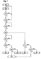
- FIG. 1 shows the block diagram of a higher-order method, which the current driving situation and operating conditions of the vehicle sorted and checked which of the cases of the sub-method according to the figures 2 to 5 is present.
- the method according to FIG. 2 shows the procedure when loading the cold accumulator
- Figure 3 shows the procedure when unloading the cold storage
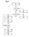
- Figure 4 shows the procedure for Loading the heat accumulator
- Figure 5 shows the procedure at Discharging the heat accumulator. Accordingly, in a method according to Figure 1 jumps to the steps 201, 301, 401 and 501 of the figures 2, 3, 4 or 5 instead.
- step 105 If it is determined in step 105 that the interior temperature T I is within the comfort range, then a waiting loop is executed and jumped back to step 105. Otherwise, it is checked in step 106 whether heating or cooling is required.
- a heating mode is present, has when the interior temperature T I comfort range around the preset temperature T set down leaving out so deviates by more than a predetermined amount to down from the preset temperature T. It then jumps to step 111.
- step 111 is checked, whether the internal combustion engine is currently in operation. If this is the case, then is jumped to step 401 and the following regarding Figure 4 described method carried out. Otherwise, jump to step 112 and checks if the ignition 7 of the internal combustion engine is switched on is. If this is not the case, then it jumps to step 110 and determined that the vehicle was taken out of service and therefore no further regulation takes place. If it is determined in step 112, that the ignition 7 of the vehicle is turned on, it is concluded that that an interruption of the operation of the internal combustion engine. 9 is present, and it is the step 501 of the method, which is below with reference to FIG. 5, jumped.
- step 106 Was found the method in step 106 that the interior temperature TI is greater to than the preset temperature T or more than a predetermined amount according to out of the preset temperature T above differs, the cooling situation occurs and it is the step 106 for Step 107 jumped.
- step 107 of the method it is first checked whether the cooling function of the air conditioning device is activated. If this is not the case, then a waiting loop is executed until activation of the air conditioning device takes place. Only when the cooling device and cooling function of the air conditioning device is activated, is jumped from step 107 to step 108. Steps 108 and 109 correspond to steps 111 and 112 of the heating case described above. In step 108, it is thus checked whether the internal combustion engine 9 is in operation.
- FIG. 2 shows the procedure when, on the basis of step 108 of the method, it has been determined that the vehicle is to be cooled and that the internal combustion engine is currently in operation.
- step 201 it is determined that cooling of the vehicle interior and charging of the cold accumulator can be performed.
- the method is initially jumps to step 202, checked in, is whether the external temperature TA is much greater than the temperature setting is to T and which is intended to raise the temperature setting T extending around the comfort range. If there is no substantial deviation, then the process jumps to step 203, the usual temperature control of the evaporator is carried out and no load is activated. The interior temperature is then turned so controlled that they are intended in the comfort of the area around the preset temperature T moves during operation of the vehicle.
- step 202 of the method If it has been determined in step 202 of the method that the difference DT between the outside temperature T A and the temperature preset T soll deviate from one another by more than a predefined amount, then the need for cooling the vehicle interior is interrupted when the internal combustion engine 9 of the vehicle is interrupted. It is then jumped to step 204 of the method.
- step 204 of the method it is checked on the basis of operating states of the vehicle, whether a standstill of the vehicle and thus an interruption of the operation of the internal combustion engine 9 of the vehicle is to be expected.
- the vehicle speed v is used, and it is checked whether the vehicle speed v exceeds a limit value v grenz .
- air distribution management is performed. To do this, the air between the different in the vehicle interior leading nozzles distributed so that the cold on the body of the occupants is optimized is and wastes no cooling capacity of the air conditioning device becomes. In particular, the defrost, ventilation, footwell and Vorraumklappen converted. In addition, an air-side Shut off before the evaporator so that part of the Evaporator serves as a cold storage and in the shut-off area the evaporator is stored and stored a larger amount.
- the Air-side barrier covers in particular an area in an injected Flow path and / or the area in which the cold storage is off.
- an external cold storage for example, by converting a cold storage medium from the liquid be stored in the solid state (freezing), making it possible is a medium flowing through the evaporator to cooler temperature and maintain a secondary circuit to the actual cooling circuit of the Form refrigerant of the evaporator.
- Corresponding cold storage are Known here, the procedure is based on the operation of the Cold storage in principle independent.
- an air quantity management is performed.
- the blower 13 and other air dampers By driving for example, the blower 13 and other air dampers the air mass flow through the evaporator increases. So that the evaporator outlet temperature according to the requirements of the regulation of Temperature of the vehicle interior remains constant, is additionally the Increases the cooling capacity of the evaporator.
- the compensated also Increase the air mass flow or the operating state of the fan 13 the additional pressure increase through the air-side shut-off on the evaporator 12 and / or cold storage 11.
- the operation of the blower 13 is in particular by increasing the electrical drive motor supplied Increased tension.
- step 209 of the method the determination of a state of charge of the cold accumulator takes place. For this purpose, it is checked in particular whether the charging time exceeds a minimum charging time t min . It can also be checked whether the charge of the cold storage has reached a certain extent with respect to the maximum charge or if the load is sufficiently large to the given conditions of outside temperature T A , solar radiation S and interior temperature T I and temperature setting T Soll the expected duration of one or a small number of successive interruptions of the operation of the internal combustion engine is sufficient. If this is not the case, step 206 is followed by step 206 again.
- step 210 If it is determined in step 210 that cold accumulator 11 is sufficiently loaded according to these criteria, then a jump is made to step 211 and a mark is set, after which a discharge of the cold accumulator is possible. Subsequently, jump to step 212 and the loading of the cooling is stopped.
- the method can then be continued with step 101 of the method or by jumping back to step 201 of the method, and the cooling of the interior of the vehicle can be controlled by normal activation and normal operation of the air conditioning device so that the interior temperature T I does not depend on the temperature setting T set or the resulting comfort range deviates.
- FIG. 3 shows the procedure, if it has been determined in FIG. 1 that there is an interruption of the operation of the internal combustion engine and cooling of the vehicle is to be carried out during the interruption of the operation of the internal combustion engine 9.
- the discharging operation of the cold accumulator is started according to the step 301. It is transferred to step 302 and checks whether a discharge of the cold accumulator is permitted, in particular whether the signal generated in step 211 of the sufficient state of charge of the cold accumulator is present. If this is not the case, step 312 is skipped and the discharge process of the cold accumulator is not permitted. In this case, it may be possible that an interruption of the operation of the internal combustion engine is not allowed and a corresponding signal is generated, which ensures that such an interruption does not take place.
- step 302 If it was determined in step 302 that discharging the cold accumulator is permissible, it is checked according to step 303 whether the vehicle electrical system voltage U B is greater than a voltage limit U min . If this is not the case, then the process jumps to step 304 and the internal combustion engine 9 of the vehicle is put back into operation immediately. It is then concluded that the state of charge of the vehicle electrical system is not sufficient to enable a safe restarting operation of the internal combustion engine after a temporary standstill, ie an interruption of the operation of the internal combustion engine.
- step 306 an air volume management takes place.
- the amount of air flowing through the evaporator 12 and / or the cold storage 11 to be cooled, depending on the outdoor temperature T A and the sunlight S reduced.
- the blower 13 of the air conditioning device 10 is controlled via a correspondingly predetermined discharge characteristic.
- the discharge characteristic of the blower can be dependent not only on the outside temperature T A and the solar radiation S but also on the evaporator outlet temperature, the position of a blower controller and other similar variables.
- the minimization of the air mass flow through the evaporator 12 and the fan 13 has the advantage that much less cooling capacity is needed to obtain the comfortable outlet temperature at the evaporator or cold storage and thus to maintain the control range to the temperature setting T target .
- an air distribution management takes place. This is the air distributed between the various nozzles in the vehicle interior so that optimizes the distribution of coldness of the incoming air to the body of the occupants and thus no cold is wasted. In particular, this will be done the Defrost, ventilation, footwell and Vorraumklappen the air conditioning device driven and adjusted accordingly.
- the cold storage can be an air-side barrier in front of the evaporator and / or cold storage have been activated. For this case will be during discharge with a time delay the shut-off in the injection area the evaporator and / or the cold accumulator 11 lifted, but at the same time the remaining area of the evaporator 12 and / or cold storage 11, which had not yet been shut off, locked. This will only the area of the evaporator 12 and / or the cold accumulator 11 flows through, in which liquid, cooled refrigerant was collected, which can evaporate afterwards.
- the amount of cold present in the cold storage 11 or the evaporator 12 or a cold storage area of the evaporator 12 can be used very efficiently, the discharge temperature at the evaporator and / or the discharge temperature of the cold storage can on one be maintained comfortable level and the temperature increase in the interior is also limited or the comfort range to the temperature setting T target can be maintained.
- the state of charge of the cold accumulator is subsequently connected according to step 308 determined and can be queried, for example, by the Outlet temperature or the air temperature after evaporator is measured and checks whether a limit is exceeded to the top. Becomes For example, the temperature of 15 ° C at the evaporator and / or cold storage exceeded, the cold storage is emptied. In this case can according to step 309, either to one of the alternatively performed Method after steps 310a and 311a, 310b and 311b or 310c and 311c to be jumped.
- Each of these methods can be either after Selection by the user of the vehicle or constructive Specification by the manufacturer of the air conditioning device or the vehicle alternatively, if detected during unloading is that the cold storage of the air conditioning device is emptied, However, a further unloading of the cold storage would be required.
- step 309 If it is determined in step 309 that further discharging of the air conditioning device is not necessary, for example, because a resumption the operation of the internal combustion engine has occurred, the discharging process and jumped to step 312. Otherwise it will be from Step 309 returned to step 303 of the method.
- step 310a of the method it is checked whether a manual loading of the cold accumulator is made possible.
- an action is expected from the driver of the vehicle, for example, actuation of an activation key that starts the loading operation of the cold accumulator by putting the engine of the vehicle back into operation for a short time Air conditioning device and the compressor can be done in normal cooling mode.
- an automatic loading of the cold accumulator can take place, this takes place in accordance with the step 310b in connection with the step 311b in that an automatic commissioning of the internal combustion engine 9 of the vehicle takes place. Otherwise, it is determined according to the step 310c that a loading can not take place and the cold storage no longer brings cooling capacity.
- step 401 the loading of the heat accumulator is activated. For this purpose, it is first checked according to step 402 whether the temperature preset T setpoint is substantially greater than the outside temperature T A. If this is not the case, it is concluded in accordance with step 403 that a loading of the heat accumulator is not required, and therefore a normal heating of the vehicle interior takes place in the usual way according to step 403 of the method. Subsequently, step 405 is entered. Loading is not necessary and the process according to FIG. 4 is completed.
- step 402 If it has been determined in step 402 that there is a significant temperature deviation, then it is proceeded to step 404 and it is checked whether the vehicle state, namely the vehicle speed v, falls below a limit value v limit . If this is not the case, it is determined that an interruption of the operation of the internal combustion engine is not imminent and it is jumped to step 405 of the method.
- step 406 an air distribution management is performed, following which the air that has flowed through the heater core, between the different nozzles is distributed so that the distribution of heat at Body of the occupants is optimized and no heat is wasted.
- the defrost, ventilation and other nozzle and control flaps the air conditioning device are suitably controlled.
- an air-side shut-off can be activated before a part of the heating heat exchanger and / or heat storage, so that the heat can be stored in the shut-off area.
- the air-side shut-off can cover a region in the injected flow path and / or the region in which the heat accumulator is located.
- the state of charge of the heat accumulator is determined. For this purpose, for example, its core temperature can be detected or detected, such as a high proportion of its heat storage medium has performed a phase state change. This can also take place in that the loading time of the heat accumulator is measured and it is determined whether it has exceeded a minimum charging time t min .
- step 406 the method jumps back to step 406 and a further loading of the heat accumulator takes place. If the heat storage sufficiently charged, it is jumped to step 409 of the method and set a signal, after which the heat storage can be discharged. Subsequently, step 410 of the method is skipped and the loading of the heat accumulator is completed.
- FIG. 5 shows the procedure for discharging the heat accumulator, as it occurs when the operation of the internal combustion engine 9 is interrupted and in the case of heating.
- the procedure of Figure 5 when unloading the heat accumulator corresponds to the procedure when unloading the cold storage in accordance with reverse temperature relationship between the outside temperature T A and internal temperature T I or temperature setting T target . Nevertheless, the method steps 501 to 512 correspond to the method steps 301 to 312.
- step 501 of the method the discharge process of the heat accumulator started.
- step 502 it is first checked whether a Unloading of the heat accumulator 15 is allowed, in particular whether in step 409 of the loading method has been set a corresponding signal. Is this not the case, it jumps to step 512 and the unloading process completed.
- step 503 it is checked in step 503 whether the vehicle electrical system voltage U B exceeds a certain voltage limit U min , which is to ensure that sufficient charge capacity of the energy storage of the vehicle is present in order to maintain the vehicle during the interruption of the operation of the internal combustion engine in the required form and then start again. If the limit value is undershot, step 504 is used to jump to step 504 and the internal combustion engine 9 of the vehicle is put back into operation. Otherwise, the heating of the vehicle interior from the heat storage is performed according to the steps 505 to 508. First, according to step 505, an air management is performed, whereafter the air conditioner is switched from fresh air to recirculated air, if not already done. This has the advantage that only pre-heated air flows over the radiator and / or the heat accumulator and thus substantially less heat output to maintain the vehicle interior T I to allow the temperature setting T target around.
- an air quantity management is carried out, according to which the amount of air which is heated via the radiator and / or the heat accumulator, as a function of the outside temperature T A , the solar radiation S and the difference D T between the outside temperature T A and temperature setting T target by driving the Blower 13 to control according to a discharge characteristic of the blower.
- This also serves the purpose of reducing the heat output for maintaining the interior temperature T I in the range around the temperature setting T Soll around.
- an air distribution management is still done, so that the heated air, which the heater core 16 and / or has flowed through the heat storage 15, still in the vehicle interior is initiated, that optimizes the distribution of heat on the body of the occupants what the flaps and air ducts of the air conditioning device be controlled accordingly.
- the procedure in the refrigerant storage can also be a barrier before the Radiator deactivated and the previously not locked off area of the radiator or the heating heat exchanger are shut off, so a To allow discharge of this area.
- step 508 for example, due to the blow-off temperature downstream of the heater core 16 checks if the state of charge of the heat accumulator 15 is sufficiently large to allow further unloading. This is no longer the case, for example, when the outlet temperature downstream of the heating heat exchanger 16 is below a limit or the temperature in the heat storage falls below a limit.
- step 509 of the method it is checked whether further discharge of the heat accumulator is required and possible. If this is the case, then it jumps to step 503. If it is not possible to further discharge the heat accumulator, step 512 is entered. If a further discharging of the heat accumulator is necessary, ie further heating of the vehicle interior with energy from the heat accumulator, however, if there is no longer sufficient state of charge of the heat accumulator 15, alternatively one of the methods according to steps 510a and 511a, 510b and 511b resp 510c and 511c, wherein the selection of the method is made either constructively or by the driver. According to step 510a, a manual loading of the heat accumulator takes place.
- a recommissioning of the internal combustion engine 9 of the vehicle is then carried out if the driver expresses a corresponding request by actuating a corresponding operating element.
- an automatic loading of the heat accumulator takes place in which automatic commissioning of the internal combustion engine 9 takes place according to step 511b.
- an emergency air management is then activated to minimize the deterioration of the thermal comfort in the vehicle interior until the interruption of the operation of the internal combustion engine 9 is completed.
- the amount of air ie the operation of the blower 13 of the vehicle and the position of circulating air and fresh air operation in dependence on parameters such as outdoor temperature T A , internal temperature T I and the sun load is set.
Landscapes
- Engineering & Computer Science (AREA)
- Physics & Mathematics (AREA)
- Thermal Sciences (AREA)
- Mechanical Engineering (AREA)
- Radar, Positioning & Navigation (AREA)
- Remote Sensing (AREA)
- Air-Conditioning For Vehicles (AREA)
- Air Conditioning Control Device (AREA)
Abstract
Description
- Figuren 1 bis 5
- das Blockdiagramm eines erfindungsgemäßen Verfahrens zum Betreiben einer Klimatisierungseinrichtung sowohl für das Kühlen als auch das Beheizen des Fahrzeugs; und
- Figur 6
- in schematischer Blockdarstellung eine Klimatisierungs-einrichtung für Fahrzeuge, welche zum Durchführen erfindungsgemäßer Verfahren geeignet ist.
Der Luftmassenstrom von Luft zum Innenraum des Fahrzeugs wird durch ein Gebläse 13 erzeugt, wobei der Luftmassenstrom danach auf Verdampfer bzw. Kältespeicher 11 und/oder Heizungswärmetauscher 16 bzw. Wärmespeicher 15 aufgeteilt wird, um die Zufuhr eines entsprechend konditionierten Luftstromes in den Fahrzeuginnenraum zu erzeugen, wobei stromabwärts noch diverse Schaltklappen in den Luftführungskanälen vorgesehen sind, so dass der Luftstrom in unterschiedlicher Intensität durch verschiedene in unterschiedlichen Bereichen des Fahrzeuginnenraums angeordnete Luftaustrittsdüsen im Fahrzeuginnenraum verteilt werden kann. Durch geeignetes Mischen der Luftmassenströme über Verdampfer 12 bzw. Kältespeicher 11 und Heizungswärmetauscher 16 bzw. Wärmespeicher 15 kann ein vorgegebener Grad an Luftfeuchtigkeit und Lufttemperatur des Luftmassenstroms erzeugt werden, wobei durch unterschiedliche Mischungsgrade auch unterschiedliche Luftschichtungen im Fahrzeuginnenraum erzeugbar sind. Derartige Klimatisierungseinrichtungen sind auch allgemein aus Fahrzeugen bekannt.
Claims (36)
- Verfahren zum Betreiben einer Klimatisierungseinrichtung (10) für Fahrzeuge,dadurch gekennzeichnet, dassmit einer Brennkraftmaschine (9) zum Betreiben des Fahrzeugs und einer Einrichtung (8) zum Unterbrechen des Betriebs der Brennkraftmaschine (9) im Fahrzeugstillstand für die Dauer des Fahrzeugstillstands,wobei im Betrieb des Fahrzeugs das Aufladen wenigstens eines Kältespeichers (11) erfolgt undwährend einer Unterbrechung des Betriebes der Brennkraftmaschine (9) ein Kühlen des Fahrzeugsinnenraums unter Ausnutzung der im Kältespeicher gespeicherten Energie erfolgen kann,
das Beladen des Kältespeichers in Abhängigkeit von Betriebszuständen des Fahrzeugs erfolgt. - Verfahren nach Anspruch 1, dadurch gekennzeichnet, dass als Betriebszustand des Fahrzeugs eine die Wahrscheinlichkeit des Auftretens einer Unterbrechung des Betriebs der Brennkraftmaschine (9) repräsentierende Größe herangezogen wird.
- Verfahren nach einem der Ansprüche 1 oder 2, dadurch gekennzeichnet, dass als Betriebszustand des Fahrzeugs die Fahrzeuggeschwindigkeit (v) herangezogen wird, wobei insbesondere vorgesehen ist, dass ein Beladen des Kältespeichers (11) dann erfolgt, wenn die Fahrzeugsgeschwindigkeit (v) kleiner als eine Grenzgeschwindigkeit (vgrenz) ist, wobei die Grenzgeschwindigkeit (vgrenz) insbesondere oberhalb der im Stadtverkehr zulässigen Geschwindigkeiten und insbesondere im Bereich von 60 bis 80 km/h liegt.
- Verfahren nach einem der vorhergehenden Ansprüche, dadurch gekennzeichnet, dass das Beladen des Kältespeichers in Abhängigkeit einer Temperaturvorgabe (TSoll) für den Innenraum des Fahrzeugs erfolgt.
- Verfahren nach Anspruch 4, dadurch gekennzeichnet, dass das Beladen nur dann erfolgt, wenn die Außentemperatur (TA) größer ist als die Temperaturvorgabe (TSoll) und insbesondere um mehr als ein bestimmtes Maß von der Temperaturvorgabe (TSoll) nach oben abweicht.
- Verfahren nach einem der vorhergehenden Ansprüche, dadurch gekennzeichnet, dass das Unterbrechen des Betriebs der Brennkraftmaschine unterdrückt wird, soweit nicht ein Mindestladezustand des Kältespeichers erreicht ist.
- Verfahren nach Anspruch 6, dadurch gekennzeichnet, dass der Mindestladezustand des Kältespeichers durch eine Mindestladedauer (tmin) und/oder Höchsttemperatur (Tmax) im Kältespeicher (11) vorgegeben ist, wobei der Mindestladezustand insbesondere in Abhängigkeit von wenigstens einer der Größen aus Außentemperatur (TA), Differenz von Außentemperatur zu Temperaturvorgabe (TSoll) und Sonneneinstrahlung (S) erfolgt.
- Verfahren nach einem der vorhergehenden Ansprüche, dadurch gekennzeichnet, dass das Beladen des Kältespeichers (11) in Abhängigkeit wenigstens einer der Größen aus Innenraumtemperatur (TI), Außentemperatur (TA), Luftfeuchtigkeit und Sonneneinstrahlung (S) erfolgt.
- Verfahren nach einem der vorhergehenden Ansprüche, dadurch gekennzeichnet, dass für das Beladen des Kältespeichers (11) die Lufttemperatur am Verdampferaustritt auf das niedrigst mögliche Niveau reduziert wird, wobei vorzugsweise auch ein kurzzeitiges Unterschreiten des Gefrierpunktes (0° C) erfolgen kann.
- Verfahren nach einem der vorhergehenden Ansprüche, dadurch gekennzeichnet, dass bei einer Absenkung der Lufttemperatur am Verdampferaustritt für die Beladung des Kältespeichers (11), die Luft vor dem Eintritt in den Fahrzeuginnenraum verstärkt aufgeheizt wird.
- Verfahren zum Betreiben einer Klimatisierungseinrichtung für Fahrzeuge, mit einer Brennkraftmaschine (9) zum Betreiben des Fahrzeugs und einer Einrichtung (8) zum Unterbrechen des Betriebs der Brennkraftmaschine (9) im Fahrzeugstillstand für die Dauer des Fahrzeugstillstands, wobei im Betrieb des Fahrzeugs das Aufladen wenigstens eines Kältespeichers (11) erfolgt und während einer Unterbrechung des Betriebes der Brennkraftmaschine (9) ein Kühlen des Fahrzeugsinnenraums unter Ausnutzung der im Kältespeicher gespeicherten Energie erfolgen kann, insbesondere nach einem der vorhergehenden Ansprüche, dadurch gekennzeichnet, dass ein Kühlen des Fahrzeuginnenraums bei einer Unterbrechung des Betriebs der Brennkraftmaschine nur erfolgt, wenn Fahrzeugstillstand und eingeschaltete Zündung (7) des Fahrzeugs gegeben sind.
- Verfahren nach einem der vorhergehenden Ansprüche, dadurch gekennzeichnet, dass ein Kühlen des Fahrzeuginnenraums bei unterbrochenem Betrieb der Brennkraftmaschine (9) nur erfolgt, wenn die Bordnetzspannung (UB) einen Spannungsgrenzwert (Umin) übersteigt.
- Verfahren nach einem der vorhergehenden Ansprüche, dadurch gekennzeichnet, dass ein Kühlen des Fahrzeuginnenraums bei unterbrochenem Betrieb der Brennkraftmaschine (9) im Umluftbetrieb erfolgt.
- Verfahren nach einem der vorhergehenden Ansprüche, dadurch gekennzeichnet, dass beim Kühlen des Fahrzeuginnenraums bei unterbrochenem Betrieb der Brennkraftmaschine (9) der Luftmassenstrom über den Verdampfer (12) und/oder den Kältespeicher (11) minimiert wird.
- Verfahren nach Anspruch 15, dadurch gekennzeichnet, dass der Luftmassenstrom in Abhängigkeit wenigstens einer der Größen aus Außentemperatur (TA), Temperaturdifferenz (dT) zwischen Außentemperatur (TA) und Innenraumtemperatur (TI) und Sonneneinstrahlung (S) bestimmt wird.
- Verfahren nach einem der Ansprüche 15 oder 16, dadurch gekennzeichnet, dass der Betrieb des Gebläses (13) der Klimatisierungseinrichtung (10) in Abhängigkeit einer Entladekennlinie erfolgt, wobei die Entladekennlinie insbesondere in Abhängigkeit wenigstens einer der Größen aus Außentemperatur (TA), Sonneneinstrahlung (S), Verdampferausblastemperatur und Innenraumtemperatur (TI) vorgegeben ist.
- Verfahren nach einem der Ansprüche 12 bis 17, dadurch gekennzeichnet, dass die Luftführung und Luftverteilung der Luft zu den Luftaustrittsdüsen im Sinne des Erzeugens maximaler Kühlwirkung im Körperbereich der Fahrzeuginsassen gesteuert ist.
- Verfahren nach einem der Ansprüche 12 bis 18, dadurch gekennzeichnet, dass ein Unterdrücken der Unterbrechung des Betriebs der Brennkraftmaschine erfolgt, wenn die erzielbare Kühlleistung im unterbrochenen Betriebszustand der Brennkraftmaschine (9) eine Mindestgröße unterschreitet.
- Verfahren nach Anspruch 19, dadurch gekennzeichnet, dass als Maß für die Mindestgröße die Beladung des Kältespeichers insbesondere die Mindestladedauer (Tmin) der Beladung des Kältespeichers (11) herangezogen wird.
- Verfahren nach Anspruch 19 oder 20, dadurch gekennzeichnet, dass die Mindestgröße in Abhängigkeit wenigstens einer der Größen aus Außentemperatur (TA), Temperaturdifferenz (dT) zwischen Außentemperatur (TA) und Innenraumtemperatur (TI) und Sonneneinstrahlung (S) bestimmt wird.
- Verfahren zum Betreiben einer Klimatisierungseinrichtung (10) für Fahrzeuge, mit einer Brennkraftmaschine (9) zum Betreiben des Fahrzeugs und einer Einrichtung (8) zum Unterbrechen des Betriebs der Brennkraftmaschine im Fahrzeugstillstand für die Dauer des Fahrzeugstillstands, wobei im Betrieb des Fahrzeugs das Aufladen wenigstens eines Kältespeichers erfolgt und während einer Unterbrechung des Betriebes der Brennkraftmaschine ein Kühlen des Fahrzeugsinnenraums unter Ausnutzung der im Kältespeicher (11) gespeicherten Energie erfolgen kann, insbesondere nach einem der vorhergehenden Ansprüche, dadurch gekennzeichnet, dass für das Beheizen des Fahrzeuginnenraums bei unterbrochenem Betrieb der Brennkraftmaschine ein Wärmespeicher vorgesehen ist, wobei ein Beladen des Wärmespeichers (15) in Abhängigkeit von Betriebszuständen des Fahrzeugs erfolgt.
- Verfahren nach Anspruch 22, dadurch gekennzeichnet, dass als Betriebszustand des Fahrzeugs eine die Wahrscheinlichkeit des Auftretens einer Unterbrechung des Betriebs der Brennkraftmaschine (9) repräsentierende Größe herangezogen wird.
- Verfahren nach einem der Ansprüche 22 oder 23, dadurch gekennzeichnet, dass als Betriebszustand des Fahrzeugs die Fahrzeuggeschwindigkeit (v) herangezogen wird, wobei insbesondere vorgesehen ist, dass das Beladen des Wärmespeichers (15) dann erfolgt, wenn die Fahrzeuggeschwindigkeit kleiner als eine Geschwindigkeit (vgrenz) ist, welche vorzugsweise größer gewählt ist, als die im Stadtverkehr gefahrenen Geschwindigkeiten und insbesondere im Bereich von 60 bis 80 km/h liegt.
- Verfahren nach einem der Ansprüche 22 bis 24, dadurch gekennzeichnet, dass das Beladen des Wärmespeichers (15) in Abhängigkeit einer Temperaturvorgabe (Tsoll) für den Innenraum des Fahrzeugs erfolgt.
- Verfahren nach Anspruch 25, dadurch gekennzeichnet, dass das Beladen des Wärmespeichers (15) nur erfolgt, wenn die Außentemperatur (TA) kleiner ist als die Temperaturvorgabe (Tsoll) für den Innenraum und insbesondere um mehr als ein bestimmtes Maß von der Temperaturvorgabe (Tsoll) nach unten abweicht.
- Verfahren nach einem der Ansprüche 22 bis 26, dadurch gekennzeichnet, dass das Unterbrechen des Betriebs der Brennkraftmaschine unterdrückt wird, soweit nicht ein Mindestladezustand des Wärmespeichers (15) erreicht ist, wobei der Mindestladezustand vorzugsweise durch eine Mindestladedauer (tmin) und/oder Mindesttemperatur (Tmin) im Wärmespeicher vorgegeben ist, wobei der Mindestladezustand insbesondere in Abhängigkeit wenigstens einer der Größen aus Außentemperatur (TA), Differenz (dT) von Außentemperatur (TA) zu Temperaturvorgabe (Tsoll) und Sonneneinstrahlung (S) erfolgt.
- Verfahren nach einem der Ansprüche 22 bis 27, dadurch gekennzeichnet, dass das Beladen des Wärmespeichers (15) in Abhängigkeit wenigstens einer der Größen aus Innenraumtemperatur (TI), Außentemperatur (TA), Luftfeuchtigkeit, Sonneneinstrahlung (S) erfolgt.
- Verfahren nach einem der Ansprüche 22 bis 28, dadurch gekennzeichnet, dass für das Beladen des Wärmespeichers (15) die Temperatur des Kühlmediums der Brennkraftmaschine auf einen oberen Grenzwert angehoben wird.
- Verfahren zum Betreiben einer Klimatisierungseinrichtung für Fahrzeuge, mit einer Brennkraftmaschine (9) zum Betreiben des Fahrzeugs und einer Einrichtung (8) zum Unterbrechen des Betriebs der Brennkraftmaschine (9) im Fahrzeugstillstand für die Dauer des Fahrzeugstillstands, wobei im Betrieb des Fahrzeugs das Aufladen wenigstens eines Wärmespeichers (15) erfolgt und während einer Unterbrechung des Betriebes der Brennkraftmaschine ein Heizen des Fahrzeugsinnenraums unter Ausnutzen der im Wärmespeicher (15) gespeicherten Energie erfolgen kann, vorzugsweise nach einem der vorhergehenden Ansprüche, insbesondere nach einem der Ansprüche 22 bis 29, dadurch gekennzeichnet, dass ein Beheizen des Fahrzeuginnenraums mittels der Energie eines Wärmespeichers (15) bei unterbrochenem Betrieb der Brennkraftmaschine nur erfolgt, wenn Fahrzeugstillstand und eingeschaltete Zündung des Fahrzeugs gegeben sind.
- Verfahren nach einem der Ansprüche 22 bis 30, dadurch gekennzeichnet, dass ein Heizen des Fahrzeuginnenraums bei unterbrochenem Betrieb der Brennkraftmaschine nur erfolgt, wenn die Bordnetzspannung (UB) einen Spannungsgrenzwert (Umin) übersteigt.
- Verfahren nach einem der Ansprüche 22 bis 31, dadurch gekennzeichnet, dass das Beheizen des Fahrzeuginnenraums bei unterbrochenem Betrieb der Brennkraftmaschine (9) im Umluft- oder Teilumluftbetrieb erfolgt.
- Verfahren nach einem der Ansprüche 22 bis 32, dadurch gekennzeichnet, dass beim Beheizen des Fahrzeuginnenraums bei unterbrochenem Betrieb der Brennkraftmaschine (9) der Luftmassenstrom über den Heizungswärmetauscher (16) und/oder Wärmespeicher (15) minimiert wird.
- Verfahren nach Anspruch 33, dadurch gekennzeichnet, dass der Luftmassenstrom in Abhängigkeit wenigstens einer der Größen aus Außentemperatur (TA), Differenz zwischen Außentemperatur und Temperaturvorgabe (Tsoll) und Sonneneinstrahlung (S) bestimmt wird.
- Verfahren nach einem der Ansprüche 33 oder 34, dadurch gekennzeichnet, dass der Betrieb des Gebläses (13) der Klimatisierungseinrichtung (10) in Abhängigkeit einer Entladekennlinie des Wärmespeichers (15) erfolgt, wobei die Entladekennlinie (15) insbesondere in Abhängigkeit wenigstens einer der Größen aus Außentemperatur (TA), Sonneneinstrahlung (S), Wärmetauscherausblastemperatur und Innenraumtemperatur (TI) vorgegeben ist.
- Verfahren nach einem der Ansprüche 22 bis 35, dadurch gekennzeichnet, dass die Luftführung und Luftverteilung der Luft zu den Luftaustrittsdüsen im Sinne des Erzeugens maximaler Wärmewirkung im Körperbereich der Fahrzeuginsassen gesteuert ist.
- Verfahren nach einem der Ansprüche 30 bis 36, dadurch gekennzeichnet, dass ein Unterdrücken des Unterbrechens des Betriebs der Brennkraftmaschine (9) erfolgt, soweit die erzielbare Heizleistung im unterbrochenen Betrieb der Brennkraftmaschine (9) nicht eine Mindestgröße übersteigt, wobei die Mindestgröße vorzugsweise durch eine Mindestladedauer (tmin) und/oder Mindesttemperatur (Tmin) im Wärmespeicher vorgegeben ist, wobei der Mindestladezustand insbesondere in Abhängigkeit wenigstens einer der Größen aus Außentemperatur (TA), Sonneneinstrahlung (S) und Differenz (dT) von Außentemperatur (TA) und Temperaturvorgabe (Tsoll) erfolgt.
Applications Claiming Priority (2)
| Application Number | Priority Date | Filing Date | Title |
|---|---|---|---|
| DE102004030074 | 2004-06-23 | ||
| DE102004030074A DE102004030074A1 (de) | 2004-06-23 | 2004-06-23 | Verfahren zum Betreiben einer Klimatisierungseinrichtung für Fahrzeuge |
Publications (3)
| Publication Number | Publication Date |
|---|---|
| EP1609638A2 true EP1609638A2 (de) | 2005-12-28 |
| EP1609638A3 EP1609638A3 (de) | 2006-11-08 |
| EP1609638B1 EP1609638B1 (de) | 2010-04-07 |
Family
ID=34982315
Family Applications (1)
| Application Number | Title | Priority Date | Filing Date |
|---|---|---|---|
| EP05013027A Ceased EP1609638B1 (de) | 2004-06-23 | 2005-06-16 | Verfahren zum Betreiben einer Klimatisierungseinrichtung für Fahrzeuge |
Country Status (3)
| Country | Link |
|---|---|
| EP (1) | EP1609638B1 (de) |
| AT (1) | ATE463372T1 (de) |
| DE (2) | DE102004030074A1 (de) |
Cited By (6)
| Publication number | Priority date | Publication date | Assignee | Title |
|---|---|---|---|---|
| WO2007128455A1 (de) * | 2006-05-05 | 2007-11-15 | Behr Gmbh & Co. Kg | Verfahren zum betrieb einer kraftfahrzeug-klimaanlage |
| WO2008014730A1 (de) * | 2006-08-03 | 2008-02-07 | Webasto Ag | Klimatisierungssystem für ein fahrzeug und verfharen zum steuern eines klimatisierungssystems |
| FR2909040A1 (fr) * | 2006-11-23 | 2008-05-30 | Valeo Systemes Thermiques | Installation de controle de la temperature habitacle d'un vehicule a moteur thermique redemarrable. |
| EP2098392A1 (de) * | 2008-03-04 | 2009-09-09 | Toyota Jidosha Kabusiki Kaisha | Fahrzeugheizsystem |
| DE102013202986A1 (de) * | 2013-02-22 | 2014-08-28 | Behr Gmbh & Co. Kg | Verfahren zur Regelung und/oder Steuerung eines Kältemittelkreislaufes |
| EP3381723A1 (de) * | 2017-03-25 | 2018-10-03 | MAN Truck & Bus AG | Kraftfahrzeug mit wärmespeicher und verfahren hierzu |
Families Citing this family (8)
| Publication number | Priority date | Publication date | Assignee | Title |
|---|---|---|---|---|
| WO2008014729A1 (de) | 2006-08-03 | 2008-02-07 | Webasto Ag | Klimatisierungssystem für ein fahrzeug |
| DE102006049739A1 (de) * | 2006-10-21 | 2008-04-24 | GM Global Technology Operations, Inc., Detroit | Klimaanlage für ein Kraftfahrzeug |
| DE102007003289B4 (de) * | 2007-01-23 | 2024-04-11 | Bayerische Motoren Werke Aktiengesellschaft | Verfahren zur Klimatisierung des Innenraumes eines Kraftfahrzeugs mit einer Motor-Stopp-Start-Einrichtung |
| DE102007037856A1 (de) | 2007-08-10 | 2009-02-12 | Webasto Ag | Kälte- und/oder Wärmespeicher mit kombinierter Füllzustand- und Ladezustanderfassung |
| US7861547B2 (en) | 2008-05-28 | 2011-01-04 | Gm Global Technology Operations, Inc. | HVAC system control for improved vehicle fuel economy |
| DE102012008211A1 (de) * | 2012-04-21 | 2013-10-24 | Volkswagen Ag | Klimaanlage für ein Kraftfahrzeug und Verfahren zu deren Steuerung |
| DE102012108317A1 (de) | 2012-09-07 | 2014-03-13 | Daimler Ag | Klimaanlage eines Fahrzeugs mit thermischem Speicher, Verfahren zur Optimierung der Betriebsstrategie der Klimaanlage sowie Verwendung einer Komponente eines Fahrzeugs als thermischen Speicher |
| DE102013112458A1 (de) * | 2013-09-06 | 2015-03-12 | Institut Für Luft- Und Kältetechnik Gemeinnützige Gmbh | Verfahren zum Betrieb einer Kälteanlage mit Kältespeicher sowie Kälteanlage |
Citations (3)
| Publication number | Priority date | Publication date | Assignee | Title |
|---|---|---|---|---|
| DE19753601A1 (de) | 1997-12-03 | 1999-06-10 | Behr Gmbh & Co | Kältespeicher, insbesondere für ein Kraftfahrzeug |
| EP0995621A2 (de) | 1998-10-23 | 2000-04-26 | Denso Corporation | Klimaanlage für ein Fahrzeug |
| DE10156944A1 (de) | 2001-01-05 | 2002-07-11 | Behr Gmbh & Co | Klimaanlage für ein Kraftfahrzeug |
Family Cites Families (6)
| Publication number | Priority date | Publication date | Assignee | Title |
|---|---|---|---|---|
| DE19906497C2 (de) * | 1999-02-17 | 2002-12-05 | Behr Gmbh & Co | Verfahren und Einrichtung zur Regelung einer einen Kältespeicher umfassenden Klimaanlage |
| DE19912139C1 (de) * | 1999-03-18 | 2000-05-25 | Daimler Chrysler Ag | Verfahren und Vorrichtung zum Klimatisieren eines Nutzraumes in einem Fahrzeug, insbesondere einer Fahrgastzelle eines Elektrofahrzeugs |
| JP3801027B2 (ja) * | 2001-11-26 | 2006-07-26 | 株式会社デンソー | 車両用空調装置 |
| JP3953377B2 (ja) * | 2002-07-16 | 2007-08-08 | トヨタ自動車株式会社 | 空調装置 |
| DE10247265A1 (de) * | 2002-10-10 | 2004-04-22 | Behr Gmbh & Co. | Klimaanlage für ein Fahrzeug und zugehöriges Betriebsverfahren |
| JP2004142551A (ja) * | 2002-10-23 | 2004-05-20 | Sanden Corp | 車両用空調装置 |
-
2004
- 2004-06-23 DE DE102004030074A patent/DE102004030074A1/de not_active Withdrawn
-
2005
- 2005-06-16 DE DE502005009345T patent/DE502005009345D1/de not_active Expired - Lifetime
- 2005-06-16 EP EP05013027A patent/EP1609638B1/de not_active Ceased
- 2005-06-16 AT AT05013027T patent/ATE463372T1/de not_active IP Right Cessation
Patent Citations (3)
| Publication number | Priority date | Publication date | Assignee | Title |
|---|---|---|---|---|
| DE19753601A1 (de) | 1997-12-03 | 1999-06-10 | Behr Gmbh & Co | Kältespeicher, insbesondere für ein Kraftfahrzeug |
| EP0995621A2 (de) | 1998-10-23 | 2000-04-26 | Denso Corporation | Klimaanlage für ein Fahrzeug |
| DE10156944A1 (de) | 2001-01-05 | 2002-07-11 | Behr Gmbh & Co | Klimaanlage für ein Kraftfahrzeug |
Cited By (6)
| Publication number | Priority date | Publication date | Assignee | Title |
|---|---|---|---|---|
| WO2007128455A1 (de) * | 2006-05-05 | 2007-11-15 | Behr Gmbh & Co. Kg | Verfahren zum betrieb einer kraftfahrzeug-klimaanlage |
| WO2008014730A1 (de) * | 2006-08-03 | 2008-02-07 | Webasto Ag | Klimatisierungssystem für ein fahrzeug und verfharen zum steuern eines klimatisierungssystems |
| FR2909040A1 (fr) * | 2006-11-23 | 2008-05-30 | Valeo Systemes Thermiques | Installation de controle de la temperature habitacle d'un vehicule a moteur thermique redemarrable. |
| EP2098392A1 (de) * | 2008-03-04 | 2009-09-09 | Toyota Jidosha Kabusiki Kaisha | Fahrzeugheizsystem |
| DE102013202986A1 (de) * | 2013-02-22 | 2014-08-28 | Behr Gmbh & Co. Kg | Verfahren zur Regelung und/oder Steuerung eines Kältemittelkreislaufes |
| EP3381723A1 (de) * | 2017-03-25 | 2018-10-03 | MAN Truck & Bus AG | Kraftfahrzeug mit wärmespeicher und verfahren hierzu |
Also Published As
| Publication number | Publication date |
|---|---|
| EP1609638B1 (de) | 2010-04-07 |
| EP1609638A3 (de) | 2006-11-08 |
| ATE463372T1 (de) | 2010-04-15 |
| DE102004030074A1 (de) | 2006-01-12 |
| DE502005009345D1 (de) | 2010-05-20 |
Similar Documents
| Publication | Publication Date | Title |
|---|---|---|
| DE112019005060B4 (de) | Fahrzeugklimatisierungsvorrichtung | |
| EP1609638B1 (de) | Verfahren zum Betreiben einer Klimatisierungseinrichtung für Fahrzeuge | |
| DE69413481T2 (de) | Elektrisches fahrzeug | |
| DE112019005898B4 (de) | Fahrzeugklimaanlage | |
| DE102013009732B4 (de) | Verfahren und System zur Verteilung einer Rekuperationsleistung für ein Fahrzeug | |
| DE112019006361B4 (de) | Fahrzeugklimaanlage | |
| DE102010026354B4 (de) | Klimatisierungsvorrichtung für ein Fahrzeug | |
| DE112012003599T5 (de) | Luftkonditioniervorrichtung für ein Fahrzeug | |
| DE112017000368T5 (de) | Fahrzeugklimatisierungseinrichtung | |
| DE102005005002B4 (de) | Verfahren und Vorrichtung zum Einsparen von Energie in einem Fahrzeug | |
| DE112012001744T5 (de) | Fahrzeugtemperatur-Steuervorrichtung und am Fahrzeug angebrachtes Thermosystem | |
| DE102015106711A1 (de) | Fahrzeugheizsystem und Verfahren | |
| DE102013209767A1 (de) | Fahrzeugsteuersystem | |
| DE112019006706T5 (de) | Batterietemperaturregulierungsvorrichtung eines fahrzeugs und fahrzeugklimaanlage, die diese aufweist | |
| DE10316856A1 (de) | Klimaanlage für Kraftfahrzeuge | |
| DE102013225417A1 (de) | Gebläsesteuerung für Fahrzeuge mit Start-Stopp-Motor | |
| EP2020315B1 (de) | Verfahren zum Betreiben einer Klimaanlage | |
| DE102019124637A1 (de) | Verfahren und system zum heizen eines fahrzeugs | |
| DE112021004965T5 (de) | Fahrzeugklimaanlage | |
| DE10253707A1 (de) | Regeneratives Fahrzeugbremssystem | |
| DE102016210066B4 (de) | Verfahren zum Betrieb eines Kraftfahrzeugs und Kraftfahrzeug | |
| DE112019006280B4 (de) | Fahrzeugklimaanlage | |
| EP1591282B1 (de) | Verfahren zur Steuerung einer Klimaanlage und Klimaanlage für ein Fahrzeug | |
| EP3470287A1 (de) | Vorrichtung zur klimatisierung eines schienenfahrzeuges | |
| EP3095657B1 (de) | Verfahren zur steuerung von leistungsflüssen in einem kraftfahrzeug, steuervorrichtung, sowie kraftfahrzeug |
Legal Events
| Date | Code | Title | Description |
|---|---|---|---|
| PUAI | Public reference made under article 153(3) epc to a published international application that has entered the european phase |
Free format text: ORIGINAL CODE: 0009012 |
|
| AK | Designated contracting states |
Kind code of ref document: A2 Designated state(s): AT BE BG CH CY CZ DE DK EE ES FI FR GB GR HU IE IS IT LI LT LU MC NL PL PT RO SE SI SK TR |
|
| AX | Request for extension of the european patent |
Extension state: AL BA HR LV MK YU |
|
| PUAL | Search report despatched |
Free format text: ORIGINAL CODE: 0009013 |
|
| AK | Designated contracting states |
Kind code of ref document: A3 Designated state(s): AT BE BG CH CY CZ DE DK EE ES FI FR GB GR HU IE IS IT LI LT LU MC NL PL PT RO SE SI SK TR |
|
| AX | Request for extension of the european patent |
Extension state: AL BA HR LV MK YU |
|
| 17P | Request for examination filed |
Effective date: 20070508 |
|
| AKX | Designation fees paid |
Designated state(s): AT BE BG CH CY CZ DE DK EE ES FI FR GB GR HU IE IS IT LI LT LU MC NL PL PT RO SE SI SK TR |
|
| 17Q | First examination report despatched |
Effective date: 20071122 |
|
| GRAP | Despatch of communication of intention to grant a patent |
Free format text: ORIGINAL CODE: EPIDOSNIGR1 |
|
| GRAS | Grant fee paid |
Free format text: ORIGINAL CODE: EPIDOSNIGR3 |
|
| GRAA | (expected) grant |
Free format text: ORIGINAL CODE: 0009210 |
|
| AK | Designated contracting states |
Kind code of ref document: B1 Designated state(s): AT BE BG CH CY CZ DE DK EE ES FI FR GB GR HU IE IS IT LI LT LU MC NL PL PT RO SE SI SK TR |
|
| REG | Reference to a national code |
Ref country code: GB Ref legal event code: FG4D Free format text: NOT ENGLISH |
|
| REG | Reference to a national code |
Ref country code: CH Ref legal event code: EP |
|
| REG | Reference to a national code |
Ref country code: IE Ref legal event code: FG4D Free format text: LANGUAGE OF EP DOCUMENT: GERMAN |
|
| REF | Corresponds to: |
Ref document number: 502005009345 Country of ref document: DE Date of ref document: 20100520 Kind code of ref document: P |
|
| REG | Reference to a national code |
Ref country code: NL Ref legal event code: VDEP Effective date: 20100407 |
|
| PG25 | Lapsed in a contracting state [announced via postgrant information from national office to epo] |
Ref country code: SI Free format text: LAPSE BECAUSE OF FAILURE TO SUBMIT A TRANSLATION OF THE DESCRIPTION OR TO PAY THE FEE WITHIN THE PRESCRIBED TIME-LIMIT Effective date: 20100407 |
|
| LTIE | Lt: invalidation of european patent or patent extension |
Effective date: 20100407 |
|
| REG | Reference to a national code |
Ref country code: IE Ref legal event code: FD4D |
|
| PG25 | Lapsed in a contracting state [announced via postgrant information from national office to epo] |
Ref country code: SE Free format text: LAPSE BECAUSE OF FAILURE TO SUBMIT A TRANSLATION OF THE DESCRIPTION OR TO PAY THE FEE WITHIN THE PRESCRIBED TIME-LIMIT Effective date: 20100407 Ref country code: NL Free format text: LAPSE BECAUSE OF FAILURE TO SUBMIT A TRANSLATION OF THE DESCRIPTION OR TO PAY THE FEE WITHIN THE PRESCRIBED TIME-LIMIT Effective date: 20100407 Ref country code: LT Free format text: LAPSE BECAUSE OF FAILURE TO SUBMIT A TRANSLATION OF THE DESCRIPTION OR TO PAY THE FEE WITHIN THE PRESCRIBED TIME-LIMIT Effective date: 20100407 Ref country code: ES Free format text: LAPSE BECAUSE OF FAILURE TO SUBMIT A TRANSLATION OF THE DESCRIPTION OR TO PAY THE FEE WITHIN THE PRESCRIBED TIME-LIMIT Effective date: 20100718 |
|
| PG25 | Lapsed in a contracting state [announced via postgrant information from national office to epo] |
Ref country code: IS Free format text: LAPSE BECAUSE OF FAILURE TO SUBMIT A TRANSLATION OF THE DESCRIPTION OR TO PAY THE FEE WITHIN THE PRESCRIBED TIME-LIMIT Effective date: 20100807 Ref country code: FI Free format text: LAPSE BECAUSE OF FAILURE TO SUBMIT A TRANSLATION OF THE DESCRIPTION OR TO PAY THE FEE WITHIN THE PRESCRIBED TIME-LIMIT Effective date: 20100407 |
|
| BERE | Be: lapsed |
Owner name: BEHR G.M.B.H. & CO. KG Effective date: 20100630 |
|
| PG25 | Lapsed in a contracting state [announced via postgrant information from national office to epo] |
Ref country code: PL Free format text: LAPSE BECAUSE OF FAILURE TO SUBMIT A TRANSLATION OF THE DESCRIPTION OR TO PAY THE FEE WITHIN THE PRESCRIBED TIME-LIMIT Effective date: 20100407 Ref country code: GR Free format text: LAPSE BECAUSE OF FAILURE TO SUBMIT A TRANSLATION OF THE DESCRIPTION OR TO PAY THE FEE WITHIN THE PRESCRIBED TIME-LIMIT Effective date: 20100708 Ref country code: CY Free format text: LAPSE BECAUSE OF FAILURE TO SUBMIT A TRANSLATION OF THE DESCRIPTION OR TO PAY THE FEE WITHIN THE PRESCRIBED TIME-LIMIT Effective date: 20100428 |
|
| PG25 | Lapsed in a contracting state [announced via postgrant information from national office to epo] |
Ref country code: IE Free format text: LAPSE BECAUSE OF FAILURE TO SUBMIT A TRANSLATION OF THE DESCRIPTION OR TO PAY THE FEE WITHIN THE PRESCRIBED TIME-LIMIT Effective date: 20100407 Ref country code: DK Free format text: LAPSE BECAUSE OF FAILURE TO SUBMIT A TRANSLATION OF THE DESCRIPTION OR TO PAY THE FEE WITHIN THE PRESCRIBED TIME-LIMIT Effective date: 20100407 Ref country code: MC Free format text: LAPSE BECAUSE OF NON-PAYMENT OF DUE FEES Effective date: 20100630 Ref country code: PT Free format text: LAPSE BECAUSE OF FAILURE TO SUBMIT A TRANSLATION OF THE DESCRIPTION OR TO PAY THE FEE WITHIN THE PRESCRIBED TIME-LIMIT Effective date: 20100809 Ref country code: EE Free format text: LAPSE BECAUSE OF FAILURE TO SUBMIT A TRANSLATION OF THE DESCRIPTION OR TO PAY THE FEE WITHIN THE PRESCRIBED TIME-LIMIT Effective date: 20100407 |
|
| REG | Reference to a national code |
Ref country code: CH Ref legal event code: PL |
|
| PLBE | No opposition filed within time limit |
Free format text: ORIGINAL CODE: 0009261 |
|
| STAA | Information on the status of an ep patent application or granted ep patent |
Free format text: STATUS: NO OPPOSITION FILED WITHIN TIME LIMIT |
|
| PG25 | Lapsed in a contracting state [announced via postgrant information from national office to epo] |
Ref country code: RO Free format text: LAPSE BECAUSE OF FAILURE TO SUBMIT A TRANSLATION OF THE DESCRIPTION OR TO PAY THE FEE WITHIN THE PRESCRIBED TIME-LIMIT Effective date: 20100407 Ref country code: SK Free format text: LAPSE BECAUSE OF FAILURE TO SUBMIT A TRANSLATION OF THE DESCRIPTION OR TO PAY THE FEE WITHIN THE PRESCRIBED TIME-LIMIT Effective date: 20100407 Ref country code: CZ Free format text: LAPSE BECAUSE OF FAILURE TO SUBMIT A TRANSLATION OF THE DESCRIPTION OR TO PAY THE FEE WITHIN THE PRESCRIBED TIME-LIMIT Effective date: 20100407 |
|
| 26N | No opposition filed |
Effective date: 20110110 |
|
| GBPC | Gb: european patent ceased through non-payment of renewal fee |
Effective date: 20100707 |
|
| PG25 | Lapsed in a contracting state [announced via postgrant information from national office to epo] |
Ref country code: IT Free format text: LAPSE BECAUSE OF FAILURE TO SUBMIT A TRANSLATION OF THE DESCRIPTION OR TO PAY THE FEE WITHIN THE PRESCRIBED TIME-LIMIT Effective date: 20100407 |
|
| PG25 | Lapsed in a contracting state [announced via postgrant information from national office to epo] |
Ref country code: CH Free format text: LAPSE BECAUSE OF NON-PAYMENT OF DUE FEES Effective date: 20100630 Ref country code: LI Free format text: LAPSE BECAUSE OF NON-PAYMENT OF DUE FEES Effective date: 20100630 |
|
| PG25 | Lapsed in a contracting state [announced via postgrant information from national office to epo] |
Ref country code: BE Free format text: LAPSE BECAUSE OF NON-PAYMENT OF DUE FEES Effective date: 20100630 |
|
| PG25 | Lapsed in a contracting state [announced via postgrant information from national office to epo] |
Ref country code: GB Free format text: LAPSE BECAUSE OF NON-PAYMENT OF DUE FEES Effective date: 20100707 |
|
| PG25 | Lapsed in a contracting state [announced via postgrant information from national office to epo] |
Ref country code: AT Free format text: LAPSE BECAUSE OF NON-PAYMENT OF DUE FEES Effective date: 20100616 |
|
| PG25 | Lapsed in a contracting state [announced via postgrant information from national office to epo] |
Ref country code: LU Free format text: LAPSE BECAUSE OF NON-PAYMENT OF DUE FEES Effective date: 20100616 Ref country code: BG Free format text: LAPSE BECAUSE OF FAILURE TO SUBMIT A TRANSLATION OF THE DESCRIPTION OR TO PAY THE FEE WITHIN THE PRESCRIBED TIME-LIMIT Effective date: 20100407 Ref country code: HU Free format text: LAPSE BECAUSE OF FAILURE TO SUBMIT A TRANSLATION OF THE DESCRIPTION OR TO PAY THE FEE WITHIN THE PRESCRIBED TIME-LIMIT Effective date: 20101008 |
|
| PG25 | Lapsed in a contracting state [announced via postgrant information from national office to epo] |
Ref country code: TR Free format text: LAPSE BECAUSE OF FAILURE TO SUBMIT A TRANSLATION OF THE DESCRIPTION OR TO PAY THE FEE WITHIN THE PRESCRIBED TIME-LIMIT Effective date: 20100407 |
|
| PG25 | Lapsed in a contracting state [announced via postgrant information from national office to epo] |
Ref country code: BG Free format text: LAPSE BECAUSE OF FAILURE TO SUBMIT A TRANSLATION OF THE DESCRIPTION OR TO PAY THE FEE WITHIN THE PRESCRIBED TIME-LIMIT Effective date: 20100707 |
|
| REG | Reference to a national code |
Ref country code: DE Ref legal event code: R082 Ref document number: 502005009345 Country of ref document: DE Representative=s name: GRAUEL, ANDREAS, DIPL.-PHYS. DR. RER. NAT., DE |
|
| REG | Reference to a national code |
Ref country code: DE Ref legal event code: R082 Ref document number: 502005009345 Country of ref document: DE Representative=s name: GRAUEL, ANDREAS, DIPL.-PHYS. DR. RER. NAT., DE Effective date: 20150303 Ref country code: DE Ref legal event code: R081 Ref document number: 502005009345 Country of ref document: DE Owner name: MAHLE INTERNATIONAL GMBH, DE Free format text: FORMER OWNER: BEHR GMBH & CO. KG, 70469 STUTTGART, DE Effective date: 20150303 |
|
| REG | Reference to a national code |
Ref country code: FR Ref legal event code: PLFP Year of fee payment: 12 |
|
| REG | Reference to a national code |
Ref country code: FR Ref legal event code: PLFP Year of fee payment: 13 |
|
| REG | Reference to a national code |
Ref country code: FR Ref legal event code: PLFP Year of fee payment: 14 |
|
| PGFP | Annual fee paid to national office [announced via postgrant information from national office to epo] |
Ref country code: DE Payment date: 20180625 Year of fee payment: 14 |
|
| PGFP | Annual fee paid to national office [announced via postgrant information from national office to epo] |
Ref country code: FR Payment date: 20190625 Year of fee payment: 15 |
|
| REG | Reference to a national code |
Ref country code: DE Ref legal event code: R119 Ref document number: 502005009345 Country of ref document: DE |
|
| PG25 | Lapsed in a contracting state [announced via postgrant information from national office to epo] |
Ref country code: DE Free format text: LAPSE BECAUSE OF NON-PAYMENT OF DUE FEES Effective date: 20200101 |
|
| PG25 | Lapsed in a contracting state [announced via postgrant information from national office to epo] |
Ref country code: FR Free format text: LAPSE BECAUSE OF NON-PAYMENT OF DUE FEES Effective date: 20200630 |