EP1609570B1 - Système de commande d'une lame en particulier pour une machine pour le découpage de rouleaux de matériau en bande - Google Patents
Système de commande d'une lame en particulier pour une machine pour le découpage de rouleaux de matériau en bande Download PDFInfo
- Publication number
- EP1609570B1 EP1609570B1 EP20050011310 EP05011310A EP1609570B1 EP 1609570 B1 EP1609570 B1 EP 1609570B1 EP 20050011310 EP20050011310 EP 20050011310 EP 05011310 A EP05011310 A EP 05011310A EP 1609570 B1 EP1609570 B1 EP 1609570B1
- Authority
- EP
- European Patent Office
- Prior art keywords
- deformation
- blade
- cutting
- ril
- cutting blade
- Prior art date
- Legal status (The legal status is an assumption and is not a legal conclusion. Google has not performed a legal analysis and makes no representation as to the accuracy of the status listed.)
- Expired - Lifetime
Links
Images

Classifications
-
- B—PERFORMING OPERATIONS; TRANSPORTING
- B26—HAND CUTTING TOOLS; CUTTING; SEVERING
- B26D—CUTTING; DETAILS COMMON TO MACHINES FOR PERFORATING, PUNCHING, CUTTING-OUT, STAMPING-OUT OR SEVERING
- B26D7/00—Details of apparatus for cutting, cutting-out, stamping-out, punching, perforating, or severing by means other than cutting
- B26D7/22—Safety devices specially adapted for cutting machines
- B26D7/24—Safety devices specially adapted for cutting machines arranged to disable the operating means for the cutting member
-
- B—PERFORMING OPERATIONS; TRANSPORTING
- B23—MACHINE TOOLS; METAL-WORKING NOT OTHERWISE PROVIDED FOR
- B23D—PLANING; SLOTTING; SHEARING; BROACHING; SAWING; FILING; SCRAPING; LIKE OPERATIONS FOR WORKING METAL BY REMOVING MATERIAL, NOT OTHERWISE PROVIDED FOR
- B23D59/00—Accessories specially designed for sawing machines or sawing devices
- B23D59/001—Measuring or control devices, e.g. for automatic control of work feed pressure on band saw blade
- B23D59/002—Measuring or control devices, e.g. for automatic control of work feed pressure on band saw blade for the position of the saw blade
-
- B—PERFORMING OPERATIONS; TRANSPORTING
- B23—MACHINE TOOLS; METAL-WORKING NOT OTHERWISE PROVIDED FOR
- B23Q—DETAILS, COMPONENTS, OR ACCESSORIES FOR MACHINE TOOLS, e.g. ARRANGEMENTS FOR COPYING OR CONTROLLING; MACHINE TOOLS IN GENERAL CHARACTERISED BY THE CONSTRUCTION OF PARTICULAR DETAILS OR COMPONENTS; COMBINATIONS OR ASSOCIATIONS OF METAL-WORKING MACHINES, NOT DIRECTED TO A PARTICULAR RESULT
- B23Q15/00—Automatic control or regulation of feed movement, cutting velocity or position of tool or work
- B23Q15/007—Automatic control or regulation of feed movement, cutting velocity or position of tool or work while the tool acts upon the workpiece
- B23Q15/12—Adaptive control, i.e. adjusting itself to have a performance which is optimum according to a preassigned criterion
-
- B—PERFORMING OPERATIONS; TRANSPORTING
- B26—HAND CUTTING TOOLS; CUTTING; SEVERING
- B26D—CUTTING; DETAILS COMMON TO MACHINES FOR PERFORATING, PUNCHING, CUTTING-OUT, STAMPING-OUT OR SEVERING
- B26D5/00—Arrangements for operating and controlling machines or devices for cutting, cutting-out, stamping-out, punching, perforating, or severing by means other than cutting
-
- B—PERFORMING OPERATIONS; TRANSPORTING
- B27—WORKING OR PRESERVING WOOD OR SIMILAR MATERIAL; NAILING OR STAPLING MACHINES IN GENERAL
- B27B—SAWS FOR WOOD OR SIMILAR MATERIAL; COMPONENTS OR ACCESSORIES THEREFOR
- B27B5/00—Sawing machines working with circular or cylindrical saw blades; Components or equipment therefor
- B27B5/16—Saw benches
- B27B5/18—Saw benches with feedable circular saw blade, e.g. arranged on a carriage
-
- B—PERFORMING OPERATIONS; TRANSPORTING
- B26—HAND CUTTING TOOLS; CUTTING; SEVERING
- B26D—CUTTING; DETAILS COMMON TO MACHINES FOR PERFORATING, PUNCHING, CUTTING-OUT, STAMPING-OUT OR SEVERING
- B26D3/00—Cutting work characterised by the nature of the cut made; Apparatus therefor
- B26D3/16—Cutting rods or tubes transversely
-
- B—PERFORMING OPERATIONS; TRANSPORTING
- B26—HAND CUTTING TOOLS; CUTTING; SEVERING
- B26D—CUTTING; DETAILS COMMON TO MACHINES FOR PERFORATING, PUNCHING, CUTTING-OUT, STAMPING-OUT OR SEVERING
- B26D7/00—Details of apparatus for cutting, cutting-out, stamping-out, punching, perforating, or severing by means other than cutting
- B26D7/08—Means for treating work or cutting member to facilitate cutting
- B26D7/10—Means for treating work or cutting member to facilitate cutting by heating
-
- G—PHYSICS
- G05—CONTROLLING; REGULATING
- G05B—CONTROL OR REGULATING SYSTEMS IN GENERAL; FUNCTIONAL ELEMENTS OF SUCH SYSTEMS; MONITORING OR TESTING ARRANGEMENTS FOR SUCH SYSTEMS OR ELEMENTS
- G05B2219/00—Program-control systems
- G05B2219/30—Nc systems
- G05B2219/37—Measurements
- G05B2219/37386—Lateral movement of tool
-
- G—PHYSICS
- G05—CONTROLLING; REGULATING
- G05B—CONTROL OR REGULATING SYSTEMS IN GENERAL; FUNCTIONAL ELEMENTS OF SUCH SYSTEMS; MONITORING OR TESTING ARRANGEMENTS FOR SUCH SYSTEMS OR ELEMENTS
- G05B2219/00—Program-control systems
- G05B2219/30—Nc systems
- G05B2219/45—Nc applications
- G05B2219/45144—Saw
-
- G—PHYSICS
- G05—CONTROLLING; REGULATING
- G05B—CONTROL OR REGULATING SYSTEMS IN GENERAL; FUNCTIONAL ELEMENTS OF SUCH SYSTEMS; MONITORING OR TESTING ARRANGEMENTS FOR SUCH SYSTEMS OR ELEMENTS
- G05B2219/00—Program-control systems
- G05B2219/30—Nc systems
- G05B2219/49—Nc machine tool, till multiple
- G05B2219/49106—Feed as function of lateral movement of saw blade
-
- Y—GENERAL TAGGING OF NEW TECHNOLOGICAL DEVELOPMENTS; GENERAL TAGGING OF CROSS-SECTIONAL TECHNOLOGIES SPANNING OVER SEVERAL SECTIONS OF THE IPC; TECHNICAL SUBJECTS COVERED BY FORMER USPC CROSS-REFERENCE ART COLLECTIONS [XRACs] AND DIGESTS
- Y10—TECHNICAL SUBJECTS COVERED BY FORMER USPC
- Y10T—TECHNICAL SUBJECTS COVERED BY FORMER US CLASSIFICATION
- Y10T83/00—Cutting
- Y10T83/04—Processes
-
- Y—GENERAL TAGGING OF NEW TECHNOLOGICAL DEVELOPMENTS; GENERAL TAGGING OF CROSS-SECTIONAL TECHNOLOGIES SPANNING OVER SEVERAL SECTIONS OF THE IPC; TECHNICAL SUBJECTS COVERED BY FORMER USPC CROSS-REFERENCE ART COLLECTIONS [XRACs] AND DIGESTS
- Y10—TECHNICAL SUBJECTS COVERED BY FORMER USPC
- Y10T—TECHNICAL SUBJECTS COVERED BY FORMER US CLASSIFICATION
- Y10T83/00—Cutting
- Y10T83/081—With randomly actuated stopping means
- Y10T83/088—Responsive to tool detector or work-feed-means detector
- Y10T83/089—Responsive to tool characteristic
-
- Y—GENERAL TAGGING OF NEW TECHNOLOGICAL DEVELOPMENTS; GENERAL TAGGING OF CROSS-SECTIONAL TECHNOLOGIES SPANNING OVER SEVERAL SECTIONS OF THE IPC; TECHNICAL SUBJECTS COVERED BY FORMER USPC CROSS-REFERENCE ART COLLECTIONS [XRACs] AND DIGESTS
- Y10—TECHNICAL SUBJECTS COVERED BY FORMER USPC
- Y10T—TECHNICAL SUBJECTS COVERED BY FORMER US CLASSIFICATION
- Y10T83/00—Cutting
- Y10T83/303—With tool sharpener or smoother
- Y10T83/313—Spatially fixed tool
-
- Y—GENERAL TAGGING OF NEW TECHNOLOGICAL DEVELOPMENTS; GENERAL TAGGING OF CROSS-SECTIONAL TECHNOLOGIES SPANNING OVER SEVERAL SECTIONS OF THE IPC; TECHNICAL SUBJECTS COVERED BY FORMER USPC CROSS-REFERENCE ART COLLECTIONS [XRACs] AND DIGESTS
- Y10—TECHNICAL SUBJECTS COVERED BY FORMER USPC
- Y10T—TECHNICAL SUBJECTS COVERED BY FORMER US CLASSIFICATION
- Y10T83/00—Cutting
- Y10T83/707—By endless band or chain knife
- Y10T83/7101—With tool in-feed
- Y10T83/7145—By motor-driven mechanism
-
- Y—GENERAL TAGGING OF NEW TECHNOLOGICAL DEVELOPMENTS; GENERAL TAGGING OF CROSS-SECTIONAL TECHNOLOGIES SPANNING OVER SEVERAL SECTIONS OF THE IPC; TECHNICAL SUBJECTS COVERED BY FORMER USPC CROSS-REFERENCE ART COLLECTIONS [XRACs] AND DIGESTS
- Y10—TECHNICAL SUBJECTS COVERED BY FORMER USPC
- Y10T—TECHNICAL SUBJECTS COVERED BY FORMER US CLASSIFICATION
- Y10T83/00—Cutting
- Y10T83/768—Rotatable disc tool pair or tool and carrier
- Y10T83/7755—Carrier for rotatable tool movable during cutting
- Y10T83/7763—Tool carrier reciprocable rectilinearly
- Y10T83/7776—With means to reciprocate carrier
- Y10T83/778—And means to rotate tool
-
- Y—GENERAL TAGGING OF NEW TECHNOLOGICAL DEVELOPMENTS; GENERAL TAGGING OF CROSS-SECTIONAL TECHNOLOGIES SPANNING OVER SEVERAL SECTIONS OF THE IPC; TECHNICAL SUBJECTS COVERED BY FORMER USPC CROSS-REFERENCE ART COLLECTIONS [XRACs] AND DIGESTS
- Y10—TECHNICAL SUBJECTS COVERED BY FORMER USPC
- Y10T—TECHNICAL SUBJECTS COVERED BY FORMER US CLASSIFICATION
- Y10T83/00—Cutting
- Y10T83/768—Rotatable disc tool pair or tool and carrier
- Y10T83/7793—Means to rotate or oscillate tool
Definitions
- the present invention refers to a cutting blade control system, particularly for cutting-off machines for cutting logs of web material.
- logs or batons are initially produced and must subsequently be cut into rolls of the desired length.
- special cutting-off machines which have one or more cutting discs or rotating band saws that are cyclically lowered onto the logs to be cut.
- the cutting blade is moved towards the logs to be cut, which are conveyed on a conveyor driven by a chain extending around idler wheels.
- Machine idle times to allow the blade to cool are calculated, entirely empirically, on the basis of the operator's professional skill. Consequently, to avoid damages to the blade, there is a tendency to stop the machine within wide safety limits, with the result of a drastic lowering of production.
- Cutting-off machines can be programmed, for example, to make a certain number of consecutive cuts and then to stop for a predetermined time to allow the blade to cool.
- the number of consecutive cuts and the idle time are determined empirically by the operator, according to the type of product to be cut.
- temperature is not a parameter easy to measure with sensors, since the steel disc of the blade is dirty with lubricant, there are often coatings, for example of Teflon, on its surface and the shiny moving surface of the blade does not accurately reflect the signals emitted by some types of temperature sensors.
- the threshold temperature beyond which no correct operation of the blade is guaranteed varies according to the type of material used to form the blades and to the quality of said blades and thus is difficult to calculate precisely.
- US 4.567.798 discloses an apparatus to maximize saw blade stiffness, during cutting, comprising a displacement probe for measuring the deflection of the blade, an electromagnet to deflect the blade and two heating coils to heat the blade.
- Object of the invention is to eliminate the drawbacks of the prior art by providing a control device for the cutting blade of a cutting-off machine for logs of web material that is reliable, practical, inexpensive and simple to make.
- Another object of the present invention is to provide a method of controlling the cutting blade of a cutting-off machine for logs of web material that makes it possible to detect the condition of the cutting blade continuously, so as to stop the machine when the conditions of the cutting blade become inoperative.
- the disc blade control system for a cutting-off machine provides for continuous measurement of the deformation of the cutting blade by means of deformation measuring means.
- a maximum threshold deformation value - above which the blade could suffer damage - and a minimum threshold deformation value - at which operation of the disc without any risk of damage is advised - are set.
- the deformation of the blade measured by the deformation measuring means is compared with the maximum threshold deformation value.
- a control signal is sent which orders the stop of the movement of the blade towards the log, thus stopping the work cycle of the machine and leaving active the motorization that transmits the rotary movement to the blade.
- the blade is allowed to cool when it remains inactive during the stopping period of the machine and then to return to the initial conditions in which its deformation remains at a value below the threshold deformation value.
- the deformation of the blade during rotation measured by the deformation measuring means is compared with the set minimum threshold deformation value.
- a control signal is sent which orders restarting of the general motorization of the machine and thus the work cycle of the machine starts again.
- This deformation control system can be combined with a cooling system which consists in blowing ventilated and/or compressed and/or cooled and/or lubricated air onto the cutting blade to reduce the cooling times thereof and to bring the blade back to initial deformation values and consequently to reduce the idle times of the machine.
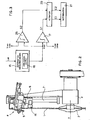
- a disc shaped cutting blade 1 is shown.
- the blade 1 is mounted on a support 2 ( Figure 2 ) formed by two disc shaped shell halves disposed on the same axis X as the blade 1.
- the support 2 is mounted rotatably on a blade-carrying arm 3 to allow the blade 1 to rotate around its own axis X.
- the blade-carrying arm 3 makes a substantially elliptical or circular movement, according to the type of machine, to bring the blade 1 toward or away from the cutting area into which the logs are fed, so as to be able to cut the logs into rolls of the desired length.
- a grinding wheel assembly 4 is mounted on the blade-carrying arm 3 for sharpening of the blade 1.
- the grinding wheel assembly 4 has substantially disc shaped sharpening grinding wheels 5, disposed slightly inclined so as to touch the cutting edge of the blade 1.
- the grinding wheels 5 are supported on a mobile support 6, substantially L-shaped in section ( Figure 1 ).
- a guide 7 in the form of a rod disposed radially with respect to the disc 1 and a threaded screw 8 disposed parallel with respect to the guide 7.
- the guide 7 and the screw 8 engage respectively in a hole 9 and in a threaded hole 10 formed in the mobile support 6.
- the guide 7 has stops 11 and 12 disposed at its ends to prevent the mobile support 6 from coming out.
- Measurement means (not shown), per se known, are provided to measure the wear on the blade 1, that is to say the decrease in the radius of the blade 1.
- a control signal is sent to the screw 8, which turns to move the mobile support 6, so that the grinding wheels 5 are always on the cutting edge of the blade 1.
- the movement of the grinding wheel assembly 4 follows the decrease in radius of the blade 1.
- Figure 1 by way of example, a situation has been shown in which the disc 1 has a maximum radius, the mobile support 6 is at the top end-of-stroke point and the grinding wheels 5 are on the cutting edge of the blade 1.
- FIG. 1 a situation is shown in which the cutting blade 1 is worn to the point of having a cutting blade 1' (shown with a thin line) with a diameter about half the diameter of the blade 1.
- the mobile support 6 of the grinding wheel assembly 4 (shown with a thin line) is at the bottom end-of-stroke point and the grinding wheels 5 are still on the cutting edge of the blade 1'.
- a deformation measuring device 15 is mounted on the mobile support 6, in a position slightly beneath the grinding wheels 5. In this manner the deformation measuring device 15 is pointed at a peripheral area of the cutting blade 1, slightly on the inside of the cutting edge which is situated in the direction of the grinding wheels 5.
- the deformation measuring device 15 being mounted on a mobile support 6, always detects deformation in the same peripheral area of the blade 1. In fact, as previously described, the mobile support 6 follows the decrease in diameter of the blade 1 due to wear thereof.
- the deformation measuring device 15 can, for example, be a device able to measure a deformation of the planarity of the blade surface, that is to say the lateral deformation (twisting) of the blade 1.
- the deformation measuring device 15 can, for example, be a distance sensor, able to measure the distance between it and the lateral surface of the blade 1 in order to have an indication of the variations in the planarity of the blade.
- the distance sensor must preferably have a resolution in the order of microns and be able to perform reading samplings in the order of milliseconds
- a laser probe provided with a laser transmitter/emitter coupled to an optical receiver/detector can be used.
- the deformation control device of the blade 1 can be combined with a blade cooling device (not shown in the figures).
- This blade cooling device provides an airing system, which blows jets of ventilated and/or compressed and/or cooled and/or lubricated air onto the blade to decrease its temperature.
- the deformation measuring device 15 measures the deformation ⁇ ril of the cutting blade 1.
- the deformation measuring device 15 comprises an analogical output 16, which emits an electrical voltage value V OUT (generally comprised between 0 - 10V) indicating the measured deformation ⁇ ril .
- the deformation value can be acquired on each reading or can be worked out by calculating a mean value of a reading sampling (quadratic mean, maximum deviation, arithmetic mean of deviations, and the like).
- the voltage value V OUT is sent to a first comparator 17, which compares it with a threshold voltage value V max indicative of a maximum threshold deformation value ⁇ max , above which the blade 1 could suffer damages during the cutting process.
- V OUT is greater than V max , the comparator 17 gives out a signal S 1 that is sent to an actuator 20 of the general motorization 21 of the machine.
- the actuator 20 gives out a control signal C1, which stops the motorization 21, and thus the machine cycle.
- the voltage signal V OUT indicative of the measured deformation ⁇ ril
- V min a minimum threshold voltage value indicative of a minimum threshold deformation value ⁇ min , at which the cutting-off machine can safely operate without the risk of causing damages to the blade 1.
- the comparator 26 gives out a signal S2 that is sent to the actuator 20.
- the actuator 20 when the signal S2 is received, gives out a control signal C2 that restarts the motorization 21 of the machine.
- the operator Before starting the machine, the operator, according to the type of cutting blade, to the web material of the logs and to the diameter of the logs, sets the threshold deformation values ⁇ max e ⁇ min . Then the machine is started and the work cycle begins.
- the actuator 20 sends the motorization 21 the control signal C1 which stops the general motorization of the machine.
- the rotating blade 1 cools down, also thanks to the intervention of the cooling device. As a result the deformation of the blade 1 also decreases with the decreasing temperature.
- the deformation ⁇ ril measured by the deformation measuring device 15 becomes less than the set minimum threshold deformation value ⁇ min . Consequently the actuator 20 sends the motorization 21 the control signal C2 which restarts the motorization 21 and thus restarts a new work cycle.
Landscapes
- Engineering & Computer Science (AREA)
- Mechanical Engineering (AREA)
- Life Sciences & Earth Sciences (AREA)
- Forests & Forestry (AREA)
- Wood Science & Technology (AREA)
- Finish Polishing, Edge Sharpening, And Grinding By Specific Grinding Devices (AREA)
- Details Of Cutting Devices (AREA)
- Sawing (AREA)
- Treatment Of Fiber Materials (AREA)
- Crushing And Pulverization Processes (AREA)
- Control Of Cutting Processes (AREA)
- Perforating, Stamping-Out Or Severing By Means Other Than Cutting (AREA)
Claims (13)
- Machine pour le découpage de rouleaux de matériau en bande, ayant un dispositif de commande d'une lame de découpage, comprenant:- des moyens de mesure (15) aptes à mesurer des valeurs de déformation (λril) sur au moins une portion de ladite lame de découpage (1),caractérisée en ce qu'elle comprend en outre:- des moyens de comparaison (17, 26) pour comparer la valeur de déformation (λril) mesurée par lesdits moyens de mesure (15) avec au moins une valeur de déformation de seuil (λmax, λmin) réglée par un opérateur,- des moyens d'actionnement (20) pour envoyer, en fonction des signaux provenant desdits moyens de comparaison (17, 26), des signaux de commande (C1, C2) à la motorisation (21) de la machine, pour ordonner d'arrêter ou de démarrer le mouvement de la lame vers le rouleau, en arrêtant ou redémarrant ainsi le cycle de fonctionnement.
- Dispositif selon la revendication 1, caractérisé en ce que lesdits moyens de mesure de déformation (15) comprennent des moyens aptes à détecter une déformation latérale de la lame (1).
- Dispositif selon la revendication 1 ou 2, caractérisé en ce que lesdits moyens de mesure de déformation (15) comprennent au moins un capteur de distance apte à mesurer la distance entre lui-même et une portion de la lame (1).
- Dispositif selon la revendication 3, caractérisé en ce que lesdits moyens de mesure de déformation (15) comprennent au moins une sonde laser.
- Dispositif selon l'une quelconque des revendications précédentes, caractérisé en ce que les moyens de mesure (15) sont montés sur un ensemble de roue de meulage (4) fourni pour aiguiser la lame de découpage (1).
- Dispositif selon la revendication 5, caractérisé en ce que lesdits moyens de mesure (15) sont montés sur un support mobile (6) de l'ensemble de roue de meulage (4) qui se déplace en fonction de l'usure de la lame (1), qui provoque une réduction de son diamètre.
- Dispositif selon la revendication 6, caractérisé en ce que lesdits moyens de mesure (15) sont montés sur ledit support mobile (6) à une position permettant de mesurer la déformation dans une zone périphérique de la lame de découpage (1).
- Dispositif selon l'une quelconque des revendications précédentes, caractérisé en ce que ladite au moins une valeur de déformation de seuil réglée par l'opérateur fournit une valeur de déformation de seuil maximum (λmax) au-dessus de laquelle la lame de découpage (1) peut être endommagée et une valeur de déformation de seuil minimum (λmin) à laquelle la lame de découpage ne risque pas d'être endommagée.
- Dispositif selon la revendication 8, caractérisé en ce que lesdits moyens de comparaison comprennent deux comparateurs (17, 26):- un premier comparateur (17) pour comparer un signal de tension (VOUT) indicatif de ladite déformation (λril) mesurée par les moyens de mesure (15), avec un signal de tension de seuil maximum (Vmax) indicatif de ladite valeur de déformation de seuil maximum réglée (λmax), et- un deuxième comparateur (26) pour comparer ledit signal de tension (VOUT) indicatif de ladite déformation mesurée (λril), avec un signal de tension de seuil minimum (Vmin) indicatif de ladite valeur de déformation de seuil minimum réglée (λmin).
- Dispositif selon l'une quelconque des revendications précédentes, caractérisé en ce qu'il comprend en outre un dispositif de refroidissement pour la lame (1) apte à souffler de l'air ventilé et/ou comprimé et/ou refroidi et/ou lubrifié sur la lame (1).
- Procédé pour commander la déformation d'une lame de découpage (1) d'une machine pour le découpage de rouleaux de matériau en bande, comprenant les étapes suivantes:- régler au moins une valeur de déformation de seuil (λmax, λmin) de ladite lame (1);- mesurer la déformation (λril) sur au moins une portion de ladite lame de découpage (1);- comparer ladite déformation mesurée (λril) à ladite au moins une valeur de déformation préréglée (λmin, λmax),- selon le résultat de la comparaison, générer au moins un signal de commande (C1, C2) à envoyer à la motorisation (21) de la machine pour arrêter ou démarrer le mouvement de la lame vers le rouleau, en arrêtant ou redémarrant ainsi le cycle de fonctionnement.
- Procédé selon la revendication 11, caractérisé en ce que ladite étape de réglage implique de prérégler une valeur de seuil de déformation maximum (λmax), au-dessus de laquelle la lame de découpage (1) pourrait être endommagée, et une valeur de déformation de seuil minimum (λmin), à laquelle la lame de découpage (1) ne risque pas d'être endommagée.
- Procédé selon la revendication 12, caractérisé en ce que ladite étape de comparaison implique que ladite déformation mesurée (λril) soit comparée à ladite valeur de déformation de seuil maximum (λmax) ou à ladite valeur de déformation de seuil minimum (λmin) et en ce que:- si la déformation mesurée (λril) est supérieure à la valeur de déformation de seuil maximum (λmax), un signal de commande (C1) est généré pour arrêter la motorisation (21) de la machine;- si la déformation mesurée (λril) est inférieure à la valeur de déformation de seuil minimum (λmin), un signal de commande (C2) est généré pour démarrer la motorisation (21) de la machine.
Applications Claiming Priority (2)
| Application Number | Priority Date | Filing Date | Title |
|---|---|---|---|
| ITMI20041269 ITMI20041269A1 (it) | 2004-06-24 | 2004-06-24 | Sistema di controllo della lama di taglio particolarmente per macchine troncatrici per il taglio di log di materiale in foglio |
| ITMI20041269 | 2004-06-24 |
Publications (2)
| Publication Number | Publication Date |
|---|---|
| EP1609570A1 EP1609570A1 (fr) | 2005-12-28 |
| EP1609570B1 true EP1609570B1 (fr) | 2009-04-01 |
Family
ID=34936916
Family Applications (1)
| Application Number | Title | Priority Date | Filing Date |
|---|---|---|---|
| EP20050011310 Expired - Lifetime EP1609570B1 (fr) | 2004-06-24 | 2005-05-25 | Système de commande d'une lame en particulier pour une machine pour le découpage de rouleaux de matériau en bande |
Country Status (9)
| Country | Link |
|---|---|
| US (2) | US8136434B2 (fr) |
| EP (1) | EP1609570B1 (fr) |
| JP (1) | JP2006007415A (fr) |
| AT (1) | ATE427193T1 (fr) |
| CA (1) | CA2509292A1 (fr) |
| DE (1) | DE602005013608D1 (fr) |
| ES (1) | ES2322478T3 (fr) |
| IT (1) | ITMI20041269A1 (fr) |
| MX (1) | MXPA05006963A (fr) |
Cited By (2)
| Publication number | Priority date | Publication date | Assignee | Title |
|---|---|---|---|---|
| US10703002B2 (en) | 2009-11-10 | 2020-07-07 | Sacmi Cooperativa Meccanici Imola Societa' Cooperativa | Cutting apparatus and method |
| WO2021064145A1 (fr) | 2019-10-03 | 2021-04-08 | Fabio Perini S.P.A. | Machine de coupe pour produits en matériau cellulosique et procédé associé |
Families Citing this family (23)
| Publication number | Priority date | Publication date | Assignee | Title |
|---|---|---|---|---|
| TR200600864A2 (tr) * | 2006-02-24 | 2007-10-22 | Lms Maki̇na Sanayi̇ Ve Ti̇caret Li̇mi̇ted Şi̇rketi̇ | Temizlik kağıdı kesme makinası otomatik bileme tekniği. |
| US20080153402A1 (en) * | 2006-12-20 | 2008-06-26 | Christopher Arcona | Roadway grinding/cutting apparatus and monitoring system |
| ITFI20060338A1 (it) * | 2006-12-27 | 2008-06-28 | Futura Spa | Dispositivo e metodo per il raffreddamento dei mezzi di taglio dei logs in macchine troncatrici. |
| IT1397614B1 (it) * | 2009-03-31 | 2013-01-18 | Bonaccorsi | Macchina per il taglio di rotoli di carta |
| US20100264058A1 (en) * | 2009-04-15 | 2010-10-21 | Bio Clinical Development, Inc. | Product multi-pack |
| DE102012219397A1 (de) * | 2012-07-04 | 2014-01-09 | Robert Bosch Gmbh | Schnittlängenanzeigevorrichtung |
| PL230013B1 (pl) * | 2013-02-06 | 2018-09-28 | Int Tobacco Machinery Poland Spolka Z Ograniczona Odpowiedzialnoscia | Sposób i urządzenie do cięcia materiałów filtracyjnych |
| US9227288B2 (en) | 2013-03-15 | 2016-01-05 | Sca Hygiene Products Ab | Blade honing apparatus and cutting apparatus incorporating same |
| ITFI20130292A1 (it) * | 2013-11-30 | 2015-05-31 | Futura Spa | Dispositivo per il controllo dell'affilatura di lame a nastro. |
| JP6132438B2 (ja) * | 2014-03-19 | 2017-05-24 | コマツNtc株式会社 | シングルワイヤ式のワイヤソーによる切断方法およびシングルワイヤ式のワイヤソー |
| EP3194128B1 (fr) * | 2014-08-29 | 2018-09-12 | Fabio Perini S.p.A. | Machine de coupe de rondins au moyen de meules et procédé |
| JP6235453B2 (ja) * | 2014-12-24 | 2017-11-22 | Towa株式会社 | 切断装置及び切断方法 |
| US10427228B2 (en) * | 2015-09-29 | 2019-10-01 | Precision Automation, Inc. | Dynamic saw lubrication system |
| IT201600096943A1 (it) * | 2016-09-27 | 2018-03-27 | Perini Fabio Spa | Metodo per la gestione di linee di produzione e confezionamento di rotoli di carta tissue e linea utilizzante detto metodo |
| IT201700081306A1 (it) * | 2017-07-18 | 2019-01-18 | Perini Fabio Spa | Gruppo di affilatura per una lama di taglio, macchina comprendente detto gruppo e metodo |
| US11207756B2 (en) * | 2018-04-12 | 2021-12-28 | Milwaukee Electric Tool Corporation | Power tool blade type detection and automatic speed adjustment |
| ES2732222A1 (es) * | 2018-05-21 | 2019-11-21 | Open Mind Ventures S L U | Sistema de detección de deformación de cuchillas en máquinas de corte de material laminar |
| JP7468053B2 (ja) * | 2020-03-26 | 2024-04-16 | 王子ホールディングス株式会社 | 切断装置 |
| KR102167256B1 (ko) * | 2020-05-25 | 2020-10-19 | (유) 한빛글로벌 | V자 결합홈을 갖는 창호 프레임 가공장치 및 이를 이용하여 제조한 단열성 및 기밀성이 강화된 창호 프레임 |
| IT202100002093A1 (it) * | 2021-02-02 | 2022-08-02 | Futura Spa | Macchina troncatrice per il taglio trasversale di logs di materiale cartaceo. |
| CN113997358A (zh) * | 2021-11-07 | 2022-02-01 | 创识(海南)科技有限公司 | 一种木材加工用切割机刀片防切伤急停装置 |
| JP7753962B2 (ja) * | 2022-04-07 | 2025-10-15 | 王子ホールディングス株式会社 | 油処理方法及び油処理装置 |
| CN116572614B (zh) * | 2023-05-16 | 2023-11-17 | 广东丹青印务有限公司 | 一种高阻隔复合包装膜及生产装置、工艺 |
Family Cites Families (28)
| Publication number | Priority date | Publication date | Assignee | Title |
|---|---|---|---|---|
| US3380495A (en) * | 1965-12-30 | 1968-04-30 | Corinth Machinery Company Inc | Digital electronic setworks control for sawmills |
| US3589482A (en) * | 1969-11-05 | 1971-06-29 | Corinth Machinery Co Inc | Air operated motor and brake with modulating control system |
| US3885487A (en) * | 1974-02-25 | 1975-05-27 | Jr Clement Walker Weston | Setworks control for sawmill |
| JPS5155404A (fr) | 1974-11-08 | 1976-05-15 | Masashi Kobayashi | |
| NO139756C (no) * | 1976-12-21 | 1979-05-02 | Norsk Treteknisk Inst | Fremgangsmaate og anordning til aa kontrollere temperaturspenninger i en sagmaskins sagblad |
| US4498345A (en) * | 1982-10-04 | 1985-02-12 | Texas Instruments Incorporated | Method for measuring saw blade flexure |
| US4502459A (en) * | 1982-10-04 | 1985-03-05 | Texas Instruments Incorporated | Control of internal diameter saw blade tension in situ |
| JPS6147644A (ja) * | 1984-08-13 | 1986-03-08 | Hitachi Ltd | スライサ−用ブレ−ドのそり制御方法 |
| US4567798A (en) * | 1984-10-04 | 1986-02-04 | Cetec Engineering Co., Inc. | Apparatus to maximize saw blade stiffness |
| US4584917A (en) * | 1984-12-06 | 1986-04-29 | Paper Converting Machine Company | Automatic blade diameter compensation for log saws |
| US4971021A (en) * | 1987-07-31 | 1990-11-20 | Mitsubishi Kinzoku Kabushiki Kaisha | Apparatus for cutting semiconductor crystal |
| JPS6443050U (fr) | 1987-09-07 | 1989-03-15 | ||
| JP3250864B2 (ja) | 1993-05-18 | 2002-01-28 | 株式会社石津製作所 | トイレット用ロールペーパーの製造方法 |
| US5632666A (en) * | 1994-10-28 | 1997-05-27 | Memc Electronic Materials, Inc. | Method and apparatus for automated quality control in wafer slicing |
| US5694821A (en) * | 1995-12-08 | 1997-12-09 | Simonds Industries, Inc. | Method for controlling work feed rate for cutting wood, metal and other materials |
| US6142046A (en) * | 1996-08-06 | 2000-11-07 | Cae Machinery Ltd. | Knife projection sensing system |
| CA2251526C (fr) * | 1997-11-07 | 2006-12-05 | Terry Raff As Trustee Of The Main Children's Trust | Methode de controle de la vitesse d'avance en coupe de bois, de metaux ou d'autres materiaux |
| IT1308270B1 (it) | 1999-04-12 | 2001-12-10 | Celli Spa | Impianto e metodo per la preparazione di mandrini ed anime diavvolgimento per macchine ribobinatrici o simili |
| EP1075910A1 (fr) * | 1999-08-10 | 2001-02-14 | Fort James France | Machine de découpe d'un rouleau de papier |
| JP3373474B2 (ja) | 2000-02-18 | 2003-02-04 | 新日本化成株式会社 | シート巻取り方法 |
| IT1318030B1 (it) | 2000-06-20 | 2003-07-21 | Italconverting S P A | Sistema di controllo della temperatura della lama di taglioparticolarmente per macchine troncatrici per il taglio di log di |
| SG118084A1 (en) * | 2001-08-24 | 2006-01-27 | Micron Technology Inc | Method and apparatus for cutting semiconductor wafers |
| US7178436B2 (en) * | 2003-11-07 | 2007-02-20 | United States Steel Corporation | Method of cutting carbon and alloy steel |
| JP2006131344A (ja) | 2004-11-05 | 2006-05-25 | Bridgestone Corp | 粘着性部材用巻取ロール |
| JP4617910B2 (ja) * | 2005-02-08 | 2011-01-26 | 株式会社Sumco | 単結晶インゴットの切断方法 |
| FR2904816A1 (fr) | 2006-08-08 | 2008-02-15 | Tokheim Holding Bv | Mandrin pour rouleaux de papier destines a des distributeurs automatiques de tickets |
| CN101743186B (zh) | 2007-07-04 | 2012-12-19 | A.塞利无纺股份公司 | 用于准备缠绕心轴以形成卷筒的系统及方法 |
| SE534007C2 (sv) | 2009-04-03 | 2011-03-29 | Core Link Ab | Anordning för hantering av hylsor med och utan papper |
-
2004
- 2004-06-24 IT ITMI20041269 patent/ITMI20041269A1/it unknown
-
2005
- 2005-05-25 DE DE200560013608 patent/DE602005013608D1/de not_active Expired - Lifetime
- 2005-05-25 ES ES05011310T patent/ES2322478T3/es not_active Expired - Lifetime
- 2005-05-25 AT AT05011310T patent/ATE427193T1/de not_active IP Right Cessation
- 2005-05-25 EP EP20050011310 patent/EP1609570B1/fr not_active Expired - Lifetime
- 2005-06-02 US US11/143,527 patent/US8136434B2/en active Active
- 2005-06-07 CA CA 2509292 patent/CA2509292A1/fr not_active Abandoned
- 2005-06-24 JP JP2005185473A patent/JP2006007415A/ja active Pending
- 2005-06-24 MX MXPA05006963A patent/MXPA05006963A/es unknown
-
2012
- 2012-01-26 US US13/359,257 patent/US9308663B2/en active Active
Cited By (4)
| Publication number | Priority date | Publication date | Assignee | Title |
|---|---|---|---|---|
| US10703002B2 (en) | 2009-11-10 | 2020-07-07 | Sacmi Cooperativa Meccanici Imola Societa' Cooperativa | Cutting apparatus and method |
| WO2021064145A1 (fr) | 2019-10-03 | 2021-04-08 | Fabio Perini S.P.A. | Machine de coupe pour produits en matériau cellulosique et procédé associé |
| EP4037880A1 (fr) * | 2019-10-03 | 2022-08-10 | Körber Tissue S.p.A. | Machine de coupe pour produits en matériau cellulosique et procédé associé |
| EP4037880B1 (fr) * | 2019-10-03 | 2025-06-18 | Valmet Tissue Converting S.p.A. | Machine de coupe pour produits en matériau cellulosique et procédé associé |
Also Published As
| Publication number | Publication date |
|---|---|
| US20050284277A1 (en) | 2005-12-29 |
| US20120118118A1 (en) | 2012-05-17 |
| EP1609570A1 (fr) | 2005-12-28 |
| ATE427193T1 (de) | 2009-04-15 |
| US9308663B2 (en) | 2016-04-12 |
| ES2322478T3 (es) | 2009-06-22 |
| US8136434B2 (en) | 2012-03-20 |
| MXPA05006963A (es) | 2006-05-25 |
| ITMI20041269A1 (it) | 2004-09-24 |
| CA2509292A1 (fr) | 2005-12-24 |
| DE602005013608D1 (de) | 2009-05-14 |
| JP2006007415A (ja) | 2006-01-12 |
Similar Documents
| Publication | Publication Date | Title |
|---|---|---|
| EP1609570B1 (fr) | Système de commande d'une lame en particulier pour une machine pour le découpage de rouleaux de matériau en bande | |
| EP1110683B1 (fr) | Procédé ainsi que dispositif pour reconditionner le blanchet du cylindre d'une presse rotative d'estampage pour la production de boítes | |
| EP0817602B1 (fr) | Systeme de commande de realignement de couches-culottes | |
| US20040221699A1 (en) | Slitter apparatus with compensating device for slitter blades | |
| KR20060129091A (ko) | 컷팅 장치 | |
| US4984490A (en) | Method and apparatus for adjusting the cutting knife clearance in sheet cutters | |
| US5632666A (en) | Method and apparatus for automated quality control in wafer slicing | |
| US4517872A (en) | Controlled depth cutting method and apparatus | |
| JP2008188765A (ja) | 印刷物から形成された鱗状列流の裁断装置 | |
| EP0795278A1 (fr) | Procédé et unité pour l'alimentation en continu d'une bande de matière vers une machine | |
| CN101376224B (zh) | 用于磨削切刀的装置和方法 | |
| KR101594896B1 (ko) | 봉강 절단장치 및 봉강 절단방법 | |
| EP2957184B1 (fr) | Appareil de réglage | |
| WO1994007657A1 (fr) | Appareil de commande a distance et procede de ponçage de courroies en caoutchouc | |
| JP2006281402A (ja) | 研削作業の状態を判定する方法及び同装置、並びに研削作業の制御方法 | |
| US11504755B2 (en) | Device and method for transporting strip material, in particular a hot strip | |
| EP3838003B1 (fr) | Dispositif de découpe de l'industrie du tabac | |
| US7561940B2 (en) | Method for predictive maintenance of a cutting unit of an automatic machine | |
| ITMI20001387A1 (it) | Sistema di controllo della temperatura della lama di taglio particolarmente per macchine troncatrici per il taglio di log di materiale in fo | |
| US20220362959A1 (en) | Cutting machine for transversely cutting logs of paper material | |
| US20240109218A1 (en) | Cutting-off machine for the transversal cutting of logs of paper material | |
| CN221371653U (zh) | 一种切带机 | |
| WO2025257862A1 (fr) | Système d'affûtage automatique pour unités de coupe | |
| JP4728621B2 (ja) | 切断方法 | |
| FI20235377A1 (en) | Thermal treatment of deformable coating of a nip roll |
Legal Events
| Date | Code | Title | Description |
|---|---|---|---|
| PUAI | Public reference made under article 153(3) epc to a published international application that has entered the european phase |
Free format text: ORIGINAL CODE: 0009012 |
|
| AK | Designated contracting states |
Kind code of ref document: A1 Designated state(s): AT BE BG CH CY CZ DE DK EE ES FI FR GB GR HU IE IS IT LI LT LU MC NL PL PT RO SE SI SK TR |
|
| AX | Request for extension of the european patent |
Extension state: AL BA HR LV MK YU |
|
| 17P | Request for examination filed |
Effective date: 20060515 |
|
| AKX | Designation fees paid |
Designated state(s): AT BE BG CH CY CZ DE DK EE ES FI FR GB GR HU IE IS IT LI LT LU MC NL PL PT RO SE SI SK TR |
|
| 17Q | First examination report despatched |
Effective date: 20061026 |
|
| GRAP | Despatch of communication of intention to grant a patent |
Free format text: ORIGINAL CODE: EPIDOSNIGR1 |
|
| GRAS | Grant fee paid |
Free format text: ORIGINAL CODE: EPIDOSNIGR3 |
|
| GRAA | (expected) grant |
Free format text: ORIGINAL CODE: 0009210 |
|
| AK | Designated contracting states |
Kind code of ref document: B1 Designated state(s): AT BE BG CH CY CZ DE DK EE ES FI FR GB GR HU IE IS IT LI LT LU MC NL PL PT RO SE SI SK TR |
|
| REG | Reference to a national code |
Ref country code: GB Ref legal event code: FG4D |
|
| REG | Reference to a national code |
Ref country code: CH Ref legal event code: EP |
|
| REG | Reference to a national code |
Ref country code: IE Ref legal event code: FG4D |
|
| REF | Corresponds to: |
Ref document number: 602005013608 Country of ref document: DE Date of ref document: 20090514 Kind code of ref document: P |
|
| REG | Reference to a national code |
Ref country code: ES Ref legal event code: FG2A Ref document number: 2322478 Country of ref document: ES Kind code of ref document: T3 |
|
| PG25 | Lapsed in a contracting state [announced via postgrant information from national office to epo] |
Ref country code: SI Free format text: LAPSE BECAUSE OF FAILURE TO SUBMIT A TRANSLATION OF THE DESCRIPTION OR TO PAY THE FEE WITHIN THE PRESCRIBED TIME-LIMIT Effective date: 20090401 |
|
| NLV1 | Nl: lapsed or annulled due to failure to fulfill the requirements of art. 29p and 29m of the patents act | ||
| PG25 | Lapsed in a contracting state [announced via postgrant information from national office to epo] |
Ref country code: FI Free format text: LAPSE BECAUSE OF FAILURE TO SUBMIT A TRANSLATION OF THE DESCRIPTION OR TO PAY THE FEE WITHIN THE PRESCRIBED TIME-LIMIT Effective date: 20090401 Ref country code: AT Free format text: LAPSE BECAUSE OF FAILURE TO SUBMIT A TRANSLATION OF THE DESCRIPTION OR TO PAY THE FEE WITHIN THE PRESCRIBED TIME-LIMIT Effective date: 20090401 Ref country code: EE Free format text: LAPSE BECAUSE OF FAILURE TO SUBMIT A TRANSLATION OF THE DESCRIPTION OR TO PAY THE FEE WITHIN THE PRESCRIBED TIME-LIMIT Effective date: 20090401 Ref country code: PT Free format text: LAPSE BECAUSE OF FAILURE TO SUBMIT A TRANSLATION OF THE DESCRIPTION OR TO PAY THE FEE WITHIN THE PRESCRIBED TIME-LIMIT Effective date: 20090902 Ref country code: LT Free format text: LAPSE BECAUSE OF FAILURE TO SUBMIT A TRANSLATION OF THE DESCRIPTION OR TO PAY THE FEE WITHIN THE PRESCRIBED TIME-LIMIT Effective date: 20090401 |
|
| PG25 | Lapsed in a contracting state [announced via postgrant information from national office to epo] |
Ref country code: SE Free format text: LAPSE BECAUSE OF FAILURE TO SUBMIT A TRANSLATION OF THE DESCRIPTION OR TO PAY THE FEE WITHIN THE PRESCRIBED TIME-LIMIT Effective date: 20090701 Ref country code: IS Free format text: LAPSE BECAUSE OF FAILURE TO SUBMIT A TRANSLATION OF THE DESCRIPTION OR TO PAY THE FEE WITHIN THE PRESCRIBED TIME-LIMIT Effective date: 20090801 Ref country code: NL Free format text: LAPSE BECAUSE OF FAILURE TO SUBMIT A TRANSLATION OF THE DESCRIPTION OR TO PAY THE FEE WITHIN THE PRESCRIBED TIME-LIMIT Effective date: 20090401 Ref country code: PL Free format text: LAPSE BECAUSE OF FAILURE TO SUBMIT A TRANSLATION OF THE DESCRIPTION OR TO PAY THE FEE WITHIN THE PRESCRIBED TIME-LIMIT Effective date: 20090401 |
|
| PG25 | Lapsed in a contracting state [announced via postgrant information from national office to epo] |
Ref country code: MC Free format text: LAPSE BECAUSE OF NON-PAYMENT OF DUE FEES Effective date: 20090531 |
|
| REG | Reference to a national code |
Ref country code: CH Ref legal event code: PL |
|
| PG25 | Lapsed in a contracting state [announced via postgrant information from national office to epo] |
Ref country code: CH Free format text: LAPSE BECAUSE OF NON-PAYMENT OF DUE FEES Effective date: 20090531 Ref country code: CZ Free format text: LAPSE BECAUSE OF FAILURE TO SUBMIT A TRANSLATION OF THE DESCRIPTION OR TO PAY THE FEE WITHIN THE PRESCRIBED TIME-LIMIT Effective date: 20090401 Ref country code: LI Free format text: LAPSE BECAUSE OF NON-PAYMENT OF DUE FEES Effective date: 20090531 Ref country code: RO Free format text: LAPSE BECAUSE OF FAILURE TO SUBMIT A TRANSLATION OF THE DESCRIPTION OR TO PAY THE FEE WITHIN THE PRESCRIBED TIME-LIMIT Effective date: 20090401 Ref country code: DK Free format text: LAPSE BECAUSE OF FAILURE TO SUBMIT A TRANSLATION OF THE DESCRIPTION OR TO PAY THE FEE WITHIN THE PRESCRIBED TIME-LIMIT Effective date: 20090401 |
|
| PLBE | No opposition filed within time limit |
Free format text: ORIGINAL CODE: 0009261 |
|
| STAA | Information on the status of an ep patent application or granted ep patent |
Free format text: STATUS: NO OPPOSITION FILED WITHIN TIME LIMIT |
|
| PG25 | Lapsed in a contracting state [announced via postgrant information from national office to epo] |
Ref country code: SK Free format text: LAPSE BECAUSE OF FAILURE TO SUBMIT A TRANSLATION OF THE DESCRIPTION OR TO PAY THE FEE WITHIN THE PRESCRIBED TIME-LIMIT Effective date: 20090401 Ref country code: BE Free format text: LAPSE BECAUSE OF FAILURE TO SUBMIT A TRANSLATION OF THE DESCRIPTION OR TO PAY THE FEE WITHIN THE PRESCRIBED TIME-LIMIT Effective date: 20090401 |
|
| 26N | No opposition filed |
Effective date: 20100105 |
|
| REG | Reference to a national code |
Ref country code: IE Ref legal event code: MM4A |
|
| PG25 | Lapsed in a contracting state [announced via postgrant information from national office to epo] |
Ref country code: BG Free format text: LAPSE BECAUSE OF FAILURE TO SUBMIT A TRANSLATION OF THE DESCRIPTION OR TO PAY THE FEE WITHIN THE PRESCRIBED TIME-LIMIT Effective date: 20090701 |
|
| PG25 | Lapsed in a contracting state [announced via postgrant information from national office to epo] |
Ref country code: IE Free format text: LAPSE BECAUSE OF NON-PAYMENT OF DUE FEES Effective date: 20090525 |
|
| PG25 | Lapsed in a contracting state [announced via postgrant information from national office to epo] |
Ref country code: GR Free format text: LAPSE BECAUSE OF FAILURE TO SUBMIT A TRANSLATION OF THE DESCRIPTION OR TO PAY THE FEE WITHIN THE PRESCRIBED TIME-LIMIT Effective date: 20090702 |
|
| PG25 | Lapsed in a contracting state [announced via postgrant information from national office to epo] |
Ref country code: LU Free format text: LAPSE BECAUSE OF NON-PAYMENT OF DUE FEES Effective date: 20090525 |
|
| PG25 | Lapsed in a contracting state [announced via postgrant information from national office to epo] |
Ref country code: HU Free format text: LAPSE BECAUSE OF FAILURE TO SUBMIT A TRANSLATION OF THE DESCRIPTION OR TO PAY THE FEE WITHIN THE PRESCRIBED TIME-LIMIT Effective date: 20091002 |
|
| PG25 | Lapsed in a contracting state [announced via postgrant information from national office to epo] |
Ref country code: TR Free format text: LAPSE BECAUSE OF FAILURE TO SUBMIT A TRANSLATION OF THE DESCRIPTION OR TO PAY THE FEE WITHIN THE PRESCRIBED TIME-LIMIT Effective date: 20090401 |
|
| PG25 | Lapsed in a contracting state [announced via postgrant information from national office to epo] |
Ref country code: CY Free format text: LAPSE BECAUSE OF FAILURE TO SUBMIT A TRANSLATION OF THE DESCRIPTION OR TO PAY THE FEE WITHIN THE PRESCRIBED TIME-LIMIT Effective date: 20090401 |
|
| REG | Reference to a national code |
Ref country code: FR Ref legal event code: PLFP Year of fee payment: 11 |
|
| REG | Reference to a national code |
Ref country code: FR Ref legal event code: PLFP Year of fee payment: 12 |
|
| REG | Reference to a national code |
Ref country code: FR Ref legal event code: PLFP Year of fee payment: 13 |
|
| REG | Reference to a national code |
Ref country code: FR Ref legal event code: PLFP Year of fee payment: 14 |
|
| REG | Reference to a national code |
Ref country code: DE Ref legal event code: R082 Ref document number: 602005013608 Country of ref document: DE Representative=s name: MEISSNER BOLTE PATENTANWAELTE RECHTSANWAELTE P, DE |
|
| PGFP | Annual fee paid to national office [announced via postgrant information from national office to epo] |
Ref country code: GB Payment date: 20240508 Year of fee payment: 20 |
|
| PGFP | Annual fee paid to national office [announced via postgrant information from national office to epo] |
Ref country code: DE Payment date: 20240515 Year of fee payment: 20 |
|
| PGFP | Annual fee paid to national office [announced via postgrant information from national office to epo] |
Ref country code: ES Payment date: 20240603 Year of fee payment: 20 |
|
| PGFP | Annual fee paid to national office [announced via postgrant information from national office to epo] |
Ref country code: IT Payment date: 20240509 Year of fee payment: 20 Ref country code: FR Payment date: 20240529 Year of fee payment: 20 |
|
| REG | Reference to a national code |
Ref country code: DE Ref legal event code: R071 Ref document number: 602005013608 Country of ref document: DE |
|
| REG | Reference to a national code |
Ref country code: ES Ref legal event code: FD2A Effective date: 20250530 |
|
| REG | Reference to a national code |
Ref country code: GB Ref legal event code: PE20 Expiry date: 20250524 |
|
| PG25 | Lapsed in a contracting state [announced via postgrant information from national office to epo] |
Ref country code: ES Free format text: LAPSE BECAUSE OF EXPIRATION OF PROTECTION Effective date: 20250526 Ref country code: GB Free format text: LAPSE BECAUSE OF EXPIRATION OF PROTECTION Effective date: 20250524 |