EP1609388A1 - Dispositif de portage dorsal perfectionne - Google Patents
Dispositif de portage dorsal perfectionne Download PDFInfo
- Publication number
- EP1609388A1 EP1609388A1 EP04030225A EP04030225A EP1609388A1 EP 1609388 A1 EP1609388 A1 EP 1609388A1 EP 04030225 A EP04030225 A EP 04030225A EP 04030225 A EP04030225 A EP 04030225A EP 1609388 A1 EP1609388 A1 EP 1609388A1
- Authority
- EP
- European Patent Office
- Prior art keywords
- shoulder
- user
- yoke
- load
- strap
- Prior art date
- Legal status (The legal status is an assumption and is not a legal conclusion. Google has not performed a legal analysis and makes no representation as to the accuracy of the status listed.)
- Granted
Links
Images



Classifications
-
- A—HUMAN NECESSITIES
- A45—HAND OR TRAVELLING ARTICLES
- A45F—TRAVELLING OR CAMP EQUIPMENT: SACKS OR PACKS CARRIED ON THE BODY
- A45F3/00—Travelling or camp articles; Sacks or packs carried on the body
- A45F3/14—Carrying-straps; Pack-carrying harnesses
-
- A—HUMAN NECESSITIES
- A45—HAND OR TRAVELLING ARTICLES
- A45F—TRAVELLING OR CAMP EQUIPMENT: SACKS OR PACKS CARRIED ON THE BODY
- A45F3/00—Travelling or camp articles; Sacks or packs carried on the body
- A45F3/04—Sacks or packs carried on the body by means of two straps passing over the two shoulders
-
- A—HUMAN NECESSITIES
- A45—HAND OR TRAVELLING ARTICLES
- A45F—TRAVELLING OR CAMP EQUIPMENT: SACKS OR PACKS CARRIED ON THE BODY
- A45F3/00—Travelling or camp articles; Sacks or packs carried on the body
- A45F3/12—Shoulder-pads
-
- A—HUMAN NECESSITIES
- A45—HAND OR TRAVELLING ARTICLES
- A45F—TRAVELLING OR CAMP EQUIPMENT: SACKS OR PACKS CARRIED ON THE BODY
- A45F3/00—Travelling or camp articles; Sacks or packs carried on the body
- A45F3/04—Sacks or packs carried on the body by means of two straps passing over the two shoulders
- A45F2003/045—Sacks or packs carried on the body by means of two straps passing over the two shoulders and one additional strap around the waist
-
- A—HUMAN NECESSITIES
- A45—HAND OR TRAVELLING ARTICLES
- A45F—TRAVELLING OR CAMP EQUIPMENT: SACKS OR PACKS CARRIED ON THE BODY
- A45F3/00—Travelling or camp articles; Sacks or packs carried on the body
Definitions
- the invention relates to backpacking devices, such as backpacks, carrying racks, baby carriers, etc ...
- These devices essentially comprise means for supporting a load (closed compartment, flexible or rigid, for backpacks, rigid frame for racks, seat for baby carriers, ...) and a carrying system that is generally under the shape of two straps, each associated with a shoulder of the user.
- the system of may include other elements, including a lap belt that allows at least part of the load to be supported by the user's pelvis, relieving all the shoulders.
- Each strap is usually hooked by a top end to a part upper load support means, and by a lower end to a lower part of these support means.
- Each strap has, between its upper and lower extremities, a supporting portion that is intended to come into contact of the upper face of the user's shoulder to transfer at least a portion of the weight of the load.
- this bearing portion of the carrying system presents a maximum transversal width of the order of 5 to 8 centimeters, and it is planned to to lodge in the hollow of the shoulder, that is to say in the middle part of the shoulder according to the transverse direction. This provision is sought because it ensures a good stability of the ramp.
- braces are such that they have a natural tendency to come and lodge themselves automatically in the hollow of the shoulder.
- the object of the invention is therefore to propose a new conception of the system of portage which allows in particular to improve the comfort and the stability of portage.
- the invention proposes a back-carrying device, of the type comprising a carrying system to support the shoulders of a user at least part of a load arranged next to the back of the user, characterized in that that the carrying system has, for each shoulder, a supporting yoke which transversely covers said shoulder of the user at least to the end side of the shoulder.
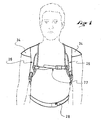
- FIGS. 1 and 2 show schematically a first embodiment of realization of a carrying device 10 according to the teachings of the invention.
- the carrying device 10 is here of the backpack type, that is to say that it comprises a resealable compartment 12 for containing objects forming the charge within range.
- This compartment 12 is intended to be worn against the back of the user, and it is in the occurrence composed of flexible tissue panels.
- Compartment 12 has a certain thickness, and, in Figure 2, we see that it is delimited transversely by two lateral faces 14, 16 and that it has an upper portion 18 and a lower portion 20.
- the compartment 12 has, in its rear face 22 visible when the bag is worn, a vertical central opening that is closed by a zipper 24 and which gives access to the interior of the compartment 12.
- the carrying device is provided with a carrying system which comprises a pair of shoulder straps 26 and a lap belt 28.
- each strap 26 is secured, by an upper end 30, of the upper portion 18 of the compartment 12, and, by a lower end 32, the lower portion 20 of the compartment 12.
- each strap 26 is thus intended to pass overcoat one of the shoulders of the user, and to extend along his ribcage, in deviating laterally outward and backward to join, at its end lower 32, the lower portion 20 of the compartment 12 which is arranged substantially in the lower back of the user.
- the straps 26 are inextensible, or have limited and controlled extensibility.
- straps 26 and the abdominal belt 28 are of adjustable length.
- the straps 26 are equipped with an anti-separation strap 27 which connects them transversely so detachable in their front part.
- the carrying system comprises, for each shoulder, a support yoke 34 which covers transversely the said shoulder of the user at least to the lateral end 36 of the shoulder.
- the yoke extends at least slightly beyond this end of the shoulder.
- the yoke 34 is constituted of an enlarged part of each of the shoulder straps 26.
- This support yoke 34 thus extends substantially in one direction transverse to the shoulder strap so as to cover the upper surface of the shoulder, substantially from the base of the neck to the end of the shoulder, the end of the shoulder included. According to the invention, it is important that the support piece 34 comes cover this end so as to bear on the bone part of the extremity of the shoulder also called acromion. In this way, the support yoke 34, part integral part of the carrying system, allows a portion of the weight of the load to be this bony part of the shoulder, which relieves all the central part of the shoulder which, in the devices of the prior art, alone supports the entire load.
- the support yoke 34 is formed of a simple panel of substantially inextensible fabrics which is bound, for example by stitching, to the outer edge of the ramp. It covers the upper part of the shoulder and comes down slightly a few centimeters on the front and on the back, so as to have a vaulted profile that on the one hand allows him to wrap the upper part of the shoulder and who else part gives it a certain rigidity.
- the yoke 34 has a rear edge 46 which extends substantially in the transverse direction of the shoulder, and that this lateral lateral edge 46 is connected to the corresponding lateral face 14 of the compartment resealable 12 by a dorsal extension 44 which is made in the form of a textile extensible.
- This dorsal extension 44 makes it possible to firmly press the support yoke onto the shoulder and therefore to transfer some of the load on the end of the shoulder.
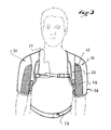
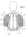
- FIGS. 3 to 7 show a second embodiment of the invention while particularly suitable for designing backpacks for practicing activities dynamic sports such as mountain biking, running, etc.
- the carrying system comprises the same resealable compartment 12 than that described for the first embodiment.
- the carrying device comprises shoulder straps 26 each provided with a support yoke 34, but the shoulder straps 26 and the support panels 34 are integrated with sleeves 38 which surround at least the upper part of each arm of the user.
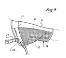
- each strap 26 forms, in the front part of the carrying system, the edge internal transverse of the corresponding sleeve 38, while the support yoke 34 forms the part of the sleeve that extends transversely outwards from the strap 26, along the upper face of the shoulder, and descending along the face external of the upper arm, for example substantially up to half height between the shoulder and the elbow.
- the parts of the sleeve 38 which form the shoulder strap 26 and the support yoke 34 are preferably substantially inextensible, or with very limited extensibility.
- the sleeve 38 is advantageously constituted of fabric panels which are preferably fabrics stretchy wide mesh allowing great freedom of movement and a very good ventilation.
- the support yoke 34 is shaped to best fit the shape of the user's shoulder, and more particularly the shape of the end 36 of the shoulder which forms a protuberance, this form of protuberance being one of the reasons why the prior art did not use this area of the shoulder as a zone of portage, because the traditional braces, too small width, could not maintain stably.
- This adaptation of the yoke 34 to the shape of the shoulder can be obtained by traditional techniques of confection, for example in with seams and pliers in appropriate places. It can also be obtained by providing the piece with a formable material, for example thermoformable, such than a foam. It will be particularly advantageous to double the yoke foam padding (or any other padding material), for added stability increased carrying system, and for even more comfort of carrying.
- the strap 26 and the support yoke 34 are connected to each other inextensible way in the area 41 corresponding to the upper face of the shoulder.
- These two elements can be made in one piece, or in two pieces juxtaposed or partially superimposed.
- the front portion 40 of the sleeve 34 is connected on the one hand to the edge before 42 of the support yoke 34, and secondly at the shoulder strap 26 (at the front).
- This front part 40 of sleeve which is extensible, thus connects the strap to the yoke support.
- the rear portion 42 of the sleeve 38 has a dorsal extension 44 which is also made of fabric with large mesh and extensible and which is bound by one of his edges at the rear edge 46 of the support yoke 34, and by another of its edges to the corresponding lateral face 14 of the resealable compartment 12.
- the support piece 34 is elastically connected on the one hand to the front part of the ramp 26 and on the other hand to the load. This results in a better transmission of forces due to the weight of the load on the end of the shoulder.
- the support yoke 34, and therefore the shoulder strap 26, being connected to the sleeve 38 they stay perfectly in place on the shoulder, even when playing sports very dynamics, such as mountain running which sometimes requires small jumps, and where the arms have an important balance role for the maintenance of the balance.
- the charge contained in the resealable compartment is therefore particularly well maintained, especially in the lateral direction, which limits the parasitic movements of the load, which can easily unbalance the user.
- the wearing comfort is improved by distributing the carrying forces over a larger area of the shoulder but especially because some of these efforts are carried over to the end zone of shoulder, bone area much less sensitive than the part of the shoulder located near the base of the neck.
Landscapes
- Portable Outdoor Equipment (AREA)
- Vehicle Body Suspensions (AREA)
- Transition And Organic Metals Composition Catalysts For Addition Polymerization (AREA)
- Eye Examination Apparatus (AREA)
- Soil Working Implements (AREA)
- Orthopedics, Nursing, And Contraception (AREA)
Abstract
Description
- les figures 1 et 2 sont des vues de face et de dos d'un premier mode de réalisation de l'invention ;
- les figures 3, 4, et 5 sont des vues de face, de dos et de côté d'un second mode de réalisation de l'invention ; et
- les figures 6 et 7 sont des vues de détail illustrant plus particulièrement une partie du dispositif des figures 3 à 5 comportant des bretelles intégrées à des manches, en vue respectivement de face et de dos.
Claims (9)
- Dispositif de portage dorsal, du type comportant un système de portage (26, 28) permettant de faire supporter par les épaules d'un utilisateur au moins une partie d'une charge agencée en regard du dos de l'utilisateur,
caractérisé en ce que le système de portage comporte, pour chaque épaule, un empiècement d'appui (34) qui recouvre transversalement ladite épaule de l'utilisateur au moins jusqu'à l'extrémité latérale de l'épaule. - Dispositif de portage dorsal selon la revendication 1, caractérisé en ce que le système de portage comporte, pour chaque épaule, une partie formant bretelle (26), et en ce que l'empiècement d'appui (34) est solidaire de la bretelle (26).
- Dispositif de portage dorsal selon l'une des revendications 1 ou 2, caractérisé en ce que l'empiècement d'appui (34) est sensiblement inextensible.
- Dispositif de portage dorsal selon l'une quelconque des revendications précédentes, caractérisé en ce que l'empiècement d'appui s'étend transversalement sur la face supérieure de l'épaule.
- Dispositif de portage dorsal selon l'une quelconque des revendications précédentes, caractérisé en ce que le dispositif comporte un compartiment (12) qui est apte à recevoir une charge et qui est agencé en regard du dos de l'utilisateur.
- Dispositif de portage dorsal selon les revendications 2 et 5 prises en combinaison, caractérisé en ce que chaque bretelle (26) présente une extrémité supérieure (30) qui est liée à une portion supérieure (18) du compartiment porte-charge, et une extrémité inférieure (32) qui est liée à une portion inférieure (20) du compartiment porte-charge (12), en ce que l'empiècement d'appui et la bretelle sont liés l'un à l'autre de manière sensiblement inextensible (40), et en ce que l'empiècement d'appui (34) et la bretelle (26) sont aussi liés l'un à l'autre par des empiècements élastiques (42).
- Dispositif de portage dorsal selon l'une quelconque des revendications précédentes, caractérisé en ce que l'empiècement d'appui (34) se prolonge transversalement le long du haut du bras de l'utilisateur.
- Dispositif de portage dorsal selon l'une quelconque des revendications précédentes, caractérisé en ce que l'empiècement d'appui (34) et des empiècements élastiques (42, 44) forment une manche (38) entourant l'épaule et le haut du bras de l'utilisateur.
- Dispositif de portage dorsal selon l'une quelconque des revendications précédentes, caractérisé en ce que l'empiècement d'appui (34) comporte un matériau de rembourrage.
Applications Claiming Priority (2)
| Application Number | Priority Date | Filing Date | Title |
|---|---|---|---|
| FR0406977A FR2872005B1 (fr) | 2004-06-25 | 2004-06-25 | Dispositif de portage dorsal perfectionne |
| FR0406977 | 2004-06-25 |
Publications (2)
| Publication Number | Publication Date |
|---|---|
| EP1609388A1 true EP1609388A1 (fr) | 2005-12-28 |
| EP1609388B1 EP1609388B1 (fr) | 2008-12-03 |
Family
ID=34949308
Family Applications (1)
| Application Number | Title | Priority Date | Filing Date |
|---|---|---|---|
| EP04030225A Expired - Lifetime EP1609388B1 (fr) | 2004-06-25 | 2004-12-21 | Dispositif de portage dorsal perfectionné |
Country Status (4)
| Country | Link |
|---|---|
| EP (1) | EP1609388B1 (fr) |
| AT (1) | ATE415837T1 (fr) |
| DE (1) | DE602004018116D1 (fr) |
| FR (1) | FR2872005B1 (fr) |
Cited By (1)
| Publication number | Priority date | Publication date | Assignee | Title |
|---|---|---|---|---|
| FR3079398A1 (fr) * | 2018-04-03 | 2019-10-04 | Serge Vigny | Sac a dos de type bolero |
Citations (3)
| Publication number | Priority date | Publication date | Assignee | Title |
|---|---|---|---|---|
| US6135333A (en) * | 1999-05-27 | 2000-10-24 | Tucker; Ronald | Game carrying hunting pack |
| WO2002082945A1 (fr) * | 2001-04-04 | 2002-10-24 | Sae Young Baek | Sac a dos |
| US20020189003A1 (en) | 2002-06-24 | 2002-12-19 | Babcock John W. | Garment for use with backpacks |
-
2004
- 2004-06-25 FR FR0406977A patent/FR2872005B1/fr not_active Expired - Fee Related
- 2004-12-21 DE DE602004018116T patent/DE602004018116D1/de not_active Expired - Lifetime
- 2004-12-21 AT AT04030225T patent/ATE415837T1/de not_active IP Right Cessation
- 2004-12-21 EP EP04030225A patent/EP1609388B1/fr not_active Expired - Lifetime
Patent Citations (3)
| Publication number | Priority date | Publication date | Assignee | Title |
|---|---|---|---|---|
| US6135333A (en) * | 1999-05-27 | 2000-10-24 | Tucker; Ronald | Game carrying hunting pack |
| WO2002082945A1 (fr) * | 2001-04-04 | 2002-10-24 | Sae Young Baek | Sac a dos |
| US20020189003A1 (en) | 2002-06-24 | 2002-12-19 | Babcock John W. | Garment for use with backpacks |
Cited By (1)
| Publication number | Priority date | Publication date | Assignee | Title |
|---|---|---|---|---|
| FR3079398A1 (fr) * | 2018-04-03 | 2019-10-04 | Serge Vigny | Sac a dos de type bolero |
Also Published As
| Publication number | Publication date |
|---|---|
| ATE415837T1 (de) | 2008-12-15 |
| EP1609388B1 (fr) | 2008-12-03 |
| FR2872005B1 (fr) | 2007-02-09 |
| DE602004018116D1 (de) | 2009-01-15 |
| FR2872005A1 (fr) | 2005-12-30 |
Similar Documents
| Publication | Publication Date | Title |
|---|---|---|
| EP0791310A1 (fr) | Sac à dos | |
| EP0735833A1 (fr) | Dispositif pour le portage de charges | |
| FR2946237A1 (fr) | Sac a dos tel qu'un sac a dos d'hydratation | |
| EP3037015A1 (fr) | Sac à dos | |
| EP3106061A1 (fr) | Article de portage | |
| EP1609388B1 (fr) | Dispositif de portage dorsal perfectionné | |
| FR3132507A1 (fr) | Harnais de parachutisme à sangle(s) lombaire(s) | |
| CA3088545C (fr) | Porte-sac et equipement comprenant un tel porte-sac | |
| FR2941196A1 (fr) | Siege pour vehicule equipe d'un harnais | |
| WO2011015769A1 (fr) | Sac a dos a leviers | |
| WO2012059698A1 (fr) | Soutien gorge à bretelles croisées comprenant des manchons de recouvrement des épaules | |
| FR2984700A1 (fr) | Sac a dos pourvu d'un systeme d'aeration du dos d'un utilisateur | |
| EP4257006B1 (fr) | Luge convertible en sac à dos | |
| EP1665959B1 (fr) | Porte-bébé ventral | |
| FR2697143A1 (fr) | Sac à dos. | |
| EP0719513A1 (fr) | Dispositif pour le portage à dos d'enfant | |
| WO2009090343A2 (fr) | Sac particulierement adapte pour transporter un ordinateur portable | |
| EP4527247B1 (fr) | Armature de sac à dos | |
| FR2770755A1 (fr) | Sac a dos ergonomique | |
| FR3020750A1 (fr) | Dispositif de maintien corporel en position debout | |
| EP2759226B1 (fr) | Perfectionnement pour sac à dos | |
| FR2703886A1 (fr) | Sac à dos adaptable à la morphologie du porteur. | |
| EP3883427A1 (fr) | Bretelle de portage comprenant une armature de conformation | |
| FR2899491A1 (fr) | Sac pour le transport de clubs de golf | |
| WO2024209099A1 (fr) | Article de portage type sac à dos ou gilet d'hydratation |
Legal Events
| Date | Code | Title | Description |
|---|---|---|---|
| PUAI | Public reference made under article 153(3) epc to a published international application that has entered the european phase |
Free format text: ORIGINAL CODE: 0009012 |
|
| 17P | Request for examination filed |
Effective date: 20041221 |
|
| AK | Designated contracting states |
Kind code of ref document: A1 Designated state(s): AT BE BG CH CY CZ DE DK EE ES FI FR GB GR HU IE IS IT LI LT LU MC NL PL PT RO SE SI SK TR |
|
| AX | Request for extension of the european patent |
Extension state: AL BA HR LV MK YU |
|
| AKX | Designation fees paid |
Designated state(s): AT BE BG CH CY CZ DE DK EE ES FI FR GB GR HU IE IS IT LI LT LU MC NL PL PT RO SE SI SK TR |
|
| 17Q | First examination report despatched |
Effective date: 20070307 |
|
| GRAP | Despatch of communication of intention to grant a patent |
Free format text: ORIGINAL CODE: EPIDOSNIGR1 |
|
| GRAS | Grant fee paid |
Free format text: ORIGINAL CODE: EPIDOSNIGR3 |
|
| GRAA | (expected) grant |
Free format text: ORIGINAL CODE: 0009210 |
|
| AK | Designated contracting states |
Kind code of ref document: B1 Designated state(s): AT BE BG CH CY CZ DE DK EE ES FI FR GB GR HU IE IS IT LI LT LU MC NL PL PT RO SE SI SK TR |
|
| REG | Reference to a national code |
Ref country code: GB Ref legal event code: FG4D Free format text: NOT ENGLISH |
|
| REG | Reference to a national code |
Ref country code: CH Ref legal event code: EP |
|
| REG | Reference to a national code |
Ref country code: IE Ref legal event code: FG4D Free format text: LANGUAGE OF EP DOCUMENT: FRENCH |
|
| REF | Corresponds to: |
Ref document number: 602004018116 Country of ref document: DE Date of ref document: 20090115 Kind code of ref document: P |
|
| PG25 | Lapsed in a contracting state [announced via postgrant information from national office to epo] |
Ref country code: LT Free format text: LAPSE BECAUSE OF FAILURE TO SUBMIT A TRANSLATION OF THE DESCRIPTION OR TO PAY THE FEE WITHIN THE PRESCRIBED TIME-LIMIT Effective date: 20081203 Ref country code: ES Free format text: LAPSE BECAUSE OF FAILURE TO SUBMIT A TRANSLATION OF THE DESCRIPTION OR TO PAY THE FEE WITHIN THE PRESCRIBED TIME-LIMIT Effective date: 20090314 |
|
| NLV1 | Nl: lapsed or annulled due to failure to fulfill the requirements of art. 29p and 29m of the patents act | ||
| PG25 | Lapsed in a contracting state [announced via postgrant information from national office to epo] |
Ref country code: PL Free format text: LAPSE BECAUSE OF FAILURE TO SUBMIT A TRANSLATION OF THE DESCRIPTION OR TO PAY THE FEE WITHIN THE PRESCRIBED TIME-LIMIT Effective date: 20081203 Ref country code: SI Free format text: LAPSE BECAUSE OF FAILURE TO SUBMIT A TRANSLATION OF THE DESCRIPTION OR TO PAY THE FEE WITHIN THE PRESCRIBED TIME-LIMIT Effective date: 20081203 Ref country code: FI Free format text: LAPSE BECAUSE OF FAILURE TO SUBMIT A TRANSLATION OF THE DESCRIPTION OR TO PAY THE FEE WITHIN THE PRESCRIBED TIME-LIMIT Effective date: 20081203 Ref country code: NL Free format text: LAPSE BECAUSE OF FAILURE TO SUBMIT A TRANSLATION OF THE DESCRIPTION OR TO PAY THE FEE WITHIN THE PRESCRIBED TIME-LIMIT Effective date: 20081203 |
|
| BERE | Be: lapsed |
Owner name: SALOMON S.A. Effective date: 20081231 |
|
| REG | Reference to a national code |
Ref country code: IE Ref legal event code: FD4D |
|
| PG25 | Lapsed in a contracting state [announced via postgrant information from national office to epo] |
Ref country code: MC Free format text: LAPSE BECAUSE OF NON-PAYMENT OF DUE FEES Effective date: 20081231 Ref country code: IE Free format text: LAPSE BECAUSE OF FAILURE TO SUBMIT A TRANSLATION OF THE DESCRIPTION OR TO PAY THE FEE WITHIN THE PRESCRIBED TIME-LIMIT Effective date: 20081203 Ref country code: RO Free format text: LAPSE BECAUSE OF FAILURE TO SUBMIT A TRANSLATION OF THE DESCRIPTION OR TO PAY THE FEE WITHIN THE PRESCRIBED TIME-LIMIT Effective date: 20081203 Ref country code: EE Free format text: LAPSE BECAUSE OF FAILURE TO SUBMIT A TRANSLATION OF THE DESCRIPTION OR TO PAY THE FEE WITHIN THE PRESCRIBED TIME-LIMIT Effective date: 20081203 Ref country code: BG Free format text: LAPSE BECAUSE OF FAILURE TO SUBMIT A TRANSLATION OF THE DESCRIPTION OR TO PAY THE FEE WITHIN THE PRESCRIBED TIME-LIMIT Effective date: 20090303 |
|
| REG | Reference to a national code |
Ref country code: CH Ref legal event code: PL |
|
| PG25 | Lapsed in a contracting state [announced via postgrant information from national office to epo] |
Ref country code: PT Free format text: LAPSE BECAUSE OF FAILURE TO SUBMIT A TRANSLATION OF THE DESCRIPTION OR TO PAY THE FEE WITHIN THE PRESCRIBED TIME-LIMIT Effective date: 20090504 Ref country code: AT Free format text: LAPSE BECAUSE OF FAILURE TO SUBMIT A TRANSLATION OF THE DESCRIPTION OR TO PAY THE FEE WITHIN THE PRESCRIBED TIME-LIMIT Effective date: 20081203 Ref country code: SE Free format text: LAPSE BECAUSE OF FAILURE TO SUBMIT A TRANSLATION OF THE DESCRIPTION OR TO PAY THE FEE WITHIN THE PRESCRIBED TIME-LIMIT Effective date: 20090303 Ref country code: CZ Free format text: LAPSE BECAUSE OF FAILURE TO SUBMIT A TRANSLATION OF THE DESCRIPTION OR TO PAY THE FEE WITHIN THE PRESCRIBED TIME-LIMIT Effective date: 20081203 Ref country code: IS Free format text: LAPSE BECAUSE OF FAILURE TO SUBMIT A TRANSLATION OF THE DESCRIPTION OR TO PAY THE FEE WITHIN THE PRESCRIBED TIME-LIMIT Effective date: 20090403 |
|
| PG25 | Lapsed in a contracting state [announced via postgrant information from national office to epo] |
Ref country code: BE Free format text: LAPSE BECAUSE OF NON-PAYMENT OF DUE FEES Effective date: 20081231 Ref country code: SK Free format text: LAPSE BECAUSE OF FAILURE TO SUBMIT A TRANSLATION OF THE DESCRIPTION OR TO PAY THE FEE WITHIN THE PRESCRIBED TIME-LIMIT Effective date: 20081203 |
|
| PLBE | No opposition filed within time limit |
Free format text: ORIGINAL CODE: 0009261 |
|
| STAA | Information on the status of an ep patent application or granted ep patent |
Free format text: STATUS: NO OPPOSITION FILED WITHIN TIME LIMIT |
|
| PG25 | Lapsed in a contracting state [announced via postgrant information from national office to epo] |
Ref country code: DK Free format text: LAPSE BECAUSE OF FAILURE TO SUBMIT A TRANSLATION OF THE DESCRIPTION OR TO PAY THE FEE WITHIN THE PRESCRIBED TIME-LIMIT Effective date: 20081203 Ref country code: CH Free format text: LAPSE BECAUSE OF NON-PAYMENT OF DUE FEES Effective date: 20081231 Ref country code: LI Free format text: LAPSE BECAUSE OF NON-PAYMENT OF DUE FEES Effective date: 20081231 |
|
| 26N | No opposition filed |
Effective date: 20090904 |
|
| GBPC | Gb: european patent ceased through non-payment of renewal fee |
Effective date: 20090303 |
|
| REG | Reference to a national code |
Ref country code: FR Ref legal event code: CJ Ref country code: FR Ref legal event code: CA |
|
| PG25 | Lapsed in a contracting state [announced via postgrant information from national office to epo] |
Ref country code: GB Free format text: LAPSE BECAUSE OF NON-PAYMENT OF DUE FEES Effective date: 20090303 |
|
| PG25 | Lapsed in a contracting state [announced via postgrant information from national office to epo] |
Ref country code: LU Free format text: LAPSE BECAUSE OF NON-PAYMENT OF DUE FEES Effective date: 20081221 Ref country code: CY Free format text: LAPSE BECAUSE OF FAILURE TO SUBMIT A TRANSLATION OF THE DESCRIPTION OR TO PAY THE FEE WITHIN THE PRESCRIBED TIME-LIMIT Effective date: 20081203 Ref country code: HU Free format text: LAPSE BECAUSE OF FAILURE TO SUBMIT A TRANSLATION OF THE DESCRIPTION OR TO PAY THE FEE WITHIN THE PRESCRIBED TIME-LIMIT Effective date: 20090604 |
|
| PG25 | Lapsed in a contracting state [announced via postgrant information from national office to epo] |
Ref country code: TR Free format text: LAPSE BECAUSE OF FAILURE TO SUBMIT A TRANSLATION OF THE DESCRIPTION OR TO PAY THE FEE WITHIN THE PRESCRIBED TIME-LIMIT Effective date: 20081203 |
|
| PG25 | Lapsed in a contracting state [announced via postgrant information from national office to epo] |
Ref country code: GR Free format text: LAPSE BECAUSE OF FAILURE TO SUBMIT A TRANSLATION OF THE DESCRIPTION OR TO PAY THE FEE WITHIN THE PRESCRIBED TIME-LIMIT Effective date: 20090304 |
|
| PGFP | Annual fee paid to national office [announced via postgrant information from national office to epo] |
Ref country code: FR Payment date: 20101224 Year of fee payment: 7 |
|
| PGFP | Annual fee paid to national office [announced via postgrant information from national office to epo] |
Ref country code: DE Payment date: 20101215 Year of fee payment: 7 |
|
| REG | Reference to a national code |
Ref country code: FR Ref legal event code: ST Effective date: 20120831 |
|
| REG | Reference to a national code |
Ref country code: DE Ref legal event code: R119 Ref document number: 602004018116 Country of ref document: DE Effective date: 20120703 |
|
| PG25 | Lapsed in a contracting state [announced via postgrant information from national office to epo] |
Ref country code: DE Free format text: LAPSE BECAUSE OF NON-PAYMENT OF DUE FEES Effective date: 20120703 |
|
| PG25 | Lapsed in a contracting state [announced via postgrant information from national office to epo] |
Ref country code: FR Free format text: LAPSE BECAUSE OF NON-PAYMENT OF DUE FEES Effective date: 20120102 |
|
| PG25 | Lapsed in a contracting state [announced via postgrant information from national office to epo] |
Ref country code: IT Free format text: LAPSE BECAUSE OF FAILURE TO SUBMIT A TRANSLATION OF THE DESCRIPTION OR TO PAY THE FEE WITHIN THE PRESCRIBED TIME-LIMIT Effective date: 20081203 |