EP1608217B1 - A set of teatcups, and a milking member - Google Patents
A set of teatcups, and a milking member Download PDFInfo
- Publication number
- EP1608217B1 EP1608217B1 EP04722489A EP04722489A EP1608217B1 EP 1608217 B1 EP1608217 B1 EP 1608217B1 EP 04722489 A EP04722489 A EP 04722489A EP 04722489 A EP04722489 A EP 04722489A EP 1608217 B1 EP1608217 B1 EP 1608217B1
- Authority
- EP
- European Patent Office
- Prior art keywords
- pair
- teatcup
- conduit portion
- liners
- length
- Prior art date
- Legal status (The legal status is an assumption and is not a legal conclusion. Google has not performed a legal analysis and makes no representation as to the accuracy of the status listed.)
- Revoked
Links
Images

Classifications
-
- A—HUMAN NECESSITIES
- A01—AGRICULTURE; FORESTRY; ANIMAL HUSBANDRY; HUNTING; TRAPPING; FISHING
- A01J—MANUFACTURE OF DAIRY PRODUCTS
- A01J5/00—Milking machines or devices
- A01J5/04—Milking machines or devices with pneumatic manipulation of teats
- A01J5/08—Teat-cups with two chambers
-
- A—HUMAN NECESSITIES
- A01—AGRICULTURE; FORESTRY; ANIMAL HUSBANDRY; HUNTING; TRAPPING; FISHING
- A01J—MANUFACTURE OF DAIRY PRODUCTS
- A01J5/00—Milking machines or devices
- A01J5/04—Milking machines or devices with pneumatic manipulation of teats
-
- A—HUMAN NECESSITIES
- A01—AGRICULTURE; FORESTRY; ANIMAL HUSBANDRY; HUNTING; TRAPPING; FISHING
- A01J—MANUFACTURE OF DAIRY PRODUCTS
- A01J5/00—Milking machines or devices
- A01J5/04—Milking machines or devices with pneumatic manipulation of teats
- A01J5/044—Milk lines or coupling devices for milk conduits
Definitions
- the present invention refers to a set of a four of teatcup liners for a milking member including a claw and four teatcups to be attached to a respective teat of an animal to be milked, each teatcup liner having a liner portion adapted to be comprised in one of said teatcups and a conduit portion adapted to extend between the respective teatcup and the claw, wherein the conduit portion of each teatcup liner has at least one property influencing the operation of the teatcup liner during milking.
- the present invention also refers to a milking member including a claw, four teatcups and a set of a four of teatcup liners, each teatcup liner having a liner portion comprised in one of said teatcups and a conduit portion extending between the respective teatcup and the claw, wherein the conduit portion of each teatcup liner has at least one property influencing the operation of the teatcup liner during milking.
- a milking member including a claw, four teatcups and a set of a four of teatcup liners, each teatcup liner having a liner portion comprised in one of said teatcups and a conduit portion extending between the respective teatcup and the claw, wherein the conduit portion of each teatcup liner has at least one property influencing the operation of the teatcup liner during milking.
- the positions of the teats of the udder of cows is in the most cases asymmetric or irregular.
- the distance between the two front teats is normally longer than the distance between the two rear teats.
- An investigation from 1983 discloses an average distance between the front teats of 150 mm, between the rear teats of 85 mm and between the rear and front teats of 100 mm.
- the front udder half is usually higher than the rear one, i.e. the two front teats are usually located at a higher position than the two rear teats.
- the teats are relatively stiff and straggling. Therefore, the teats will be relatively immovable in relation to these positions.
- US-A-6,058,880 discloses a milking member including a claw, four teatcups and a set of a four of teatcup liners.
- Each teatcup liner has a liner portion to be comprised in one of said teatcups and a conduit portion extending between the respective teatcup and the claw.
- the conduit portion of each teatcup liner is substantially identical to the conduit portion of the remaining teatcup liners.
- DE-1 027 457 discloses a milking member including a claw with four inlet nipples.
- the two inlet nipples intended for the forward teats of the animal have a length which is shorter than the length of the inlet nipples intended for the rear teats of the animal.
- US-A-631,774 discloses a milking member of a different kind.
- the milking member has four teatcups attached to a central member via a respective rigid milk conduit.
- the milk conduits extend horizontally and have a length that is adjustable by means of a telescoping mechanism.
- US,A-2,497,299 discloses a milking device having a closure plate mounted to a receptacle. From the closure plate, four short milk conduits extend to a respective teatcup attached to a respective teat of an animal to be milked. None is mentioned in US-A-2,497,299 about differing properties of the short milk conduits.
- the object of the present invention is to provide a solution to the problems discussed above.
- the first pair of said teatcup liners is adapted to be attached to the rear teats of the animal and the second pair of said teatcup liners is adapted to be attached to the forward teats of the animal.
- said property includes the length of the conduit portion, wherein the length of the first pair differs from the length of the second pair by a predetermined distance.
- the predetermined distance corresponds to the length difference between the rear teats and the forward teats of the animal, wherein the length of the first pair may be shorter than the length of the second pair.
- said property includes the flexibility of the conduit portion, wherein the flexibility of the first pair differs from the flexibility of the second pair by a predetermined value.
- a differing flexibility is advantageous when the teats of one pair of teats are directed outwardly, since the differing flexibility permits all the teatcups to be tightly attached to the respective teat.
- the flexibility of the first pair is higher than the flexibility of the second pair.
- said property includes the straightness of the conduit portion, wherein the straightness of the first pair differs from the straightness of the second pair by a predetermined value.
- the attachment of the milking member to the teats may be adapted in a better way to the shape of the udder.
- the straightness of the first pair is higher than the straightness of the second pair.
- each conduit portion of the first pair of teatcups liners may advantageously have a slightly S-like curvature in such a way that the distance between the conduit portions at the upper end in the proximity of the teatcup is shorter than at the lower end in the proximity of the claw.
- each teatcup liner is one moulded piece.
- the liner may be manufactured in an easy and convenient manner.
- a pre-formed straightness, e.g. a non-straight extension of the conduit portion, may easily be achieved by such a manufacturing method.
- the set includes a member for keeping the teatcup liners together prior to the mounting of the liners in the milking member.
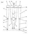
- Fig 3 discloses a milking member for the milking of an animal, e.g. a cow.
- the milking member includes a claw 1 and four teatcups 2.
- Each teatcup 2 includes a teatcup shell 3 and a teatcup liner 4, 5.
- the claw 1 may be of any conventional type, which has a housing forming an inner space for collecting the milk from each of the teatcups 2.
- the teatcup liners includes two pairs of teatcup liners 4, 5, a first pair of teatcup liners 4 and a second pair of teatcup liners 5.
- the first pair of the teatcup liners 4 is adapted to be attached to the rear teats of the animal to be milked
- the second pair of said teatcup liners 5 is adapted to be attached to the forward teats of the animal.
- Each teatcup liner 4, 5 is moulded in one piece of a rubber material to have a pre-formed shape.
- Each teatcup liner 4, 5 has a liner portion 8 and a conduit portion 9, see Figs 1 and 2 .
- the liner portion 8 is comprised in a respective one of said teatcups 2, and more precisely introduced in a respective one of the teatcup shells 3.
- the conduit portion 9 extends between the liner portion 8 and the claw 1.
- the conduit portion 9 thus has an upper end in the proximity of or adjoining the liner portion 8, and a lower end. The lower end is connected to an inlet member of the claw 1.
- the inlet member is formed by an aperture through the housing of the claw 1, wherein the lower end of the conduit portion 9 is introduced into the aperture.
- the lower end includes two ribs 10, 11 extending around the conduit portion 9.
- the ribs 10, 11 are positioned at a distance from each other.
- the inlet members also may be formed by tubular inlet nipples extending from the claw 1, wherein each inlet nipple is introduced into the lower end of the respective conduit portion 9.
- each teatcup liner 4, 5 in the proximity of the upper end of the conduit portion 9 includes two ribs 12, 13 extending around the conduit portion 9.
- the ribs 12, 13 are positioned at a distance from each other.
- each teatcup liner 4, 5 has at least one property influencing the operation of the teatcup liner 4, 5 during milking in a significant manner. More precisely, three different properties are exemplified in this application. In order to achieve an improved functioning of the milking member one, two or all of these properties are varied in a predetermined manner for the different teatcup liners 4, 5 in the set of liners to cooperate with the claw 1. In particular, said property of a first pair 8 of the four teatcup liners differs in a predetermined manner from said property of a second pair of the four teatcup liners 4, 5.
- said property refers to the length of the conduit portion 9, i.e. the length of one of said pairs differs from the length of the other of said pair by a predetermined distance 14.
- the length of the first pair of teatcup liners 4 to be attached to the rear teats is shorter than the length of the second pair of teatcup liners 5 to be attached to the forward teats. Since the rear teats normally are lower than the forward teats, this embodiment permits the claw 1 to hang down properly, i.e. without sloping in any direction.
- the predetermined distance 14 corresponds to an average length difference between the rear teats and the forward teats of an animal, for instance a cow.
- the distance 14 may be at least 10 mm, at least 20 mm, at least 30 mm or at least 40 mm.
- said property refers to the flexibility of the conduit portion 9, wherein the flexibility of the first pair of teatcup liners 4 differs from the flexibility of the second pair of teatcup liners 5 by a predetermined value.
- the flexibility of the first pair of teatcup liners 4 to be attached to the rear teats of the animal is higher than the flexibility of the second pair of teatcup liners 5 to be attached to the forward teats of the animal.
- said property refers to the straightness of the conduit portion 9, wherein the straightness of the first pair of teatcup liners 4 differs from the straightness of the second pair of teatcup liners 5 by a predetermined value.
- the straightness of the second pair of teatcup liners 5 to be attached to the forward teats of the animal is higher than the straightness of the first pair of teatcup liners 4 to be attached to the rear teats of the animal.
- each conduit portion 9 of the first pair of teatcups liners 4 has a slightly S-like curvature in such a way that the distance between the conduit portions 9 of the first pair of teatcup liners 4 at the upper end adjoining the liner portion 8 in the proximity of the teatcup shell 3 is shorter than at the lower end to be connected to the claw 1.
- first pair of teatcup liners 4 and second pair of teatcup liners 5 may be combined with each other in all possible combinations.
- first pair may be shorter and more flexible than the second pair, shorter and less straight than the second pair, more flexible and less straight than the second pair, and/or shorter, more flexible and less straight than the second pair.
- the four teatcup liners 4, 5 form a set of teatcup liners to be mounted in a respective teatcup shell 3 and attached to a claw 2 of a milking member.
- the set of teatcup liners 4, 5 may be sold and distributed to a milk farmer as one unit.
- the teatcup liners 4, 5 of the set may be kept together in a package by a member, e.g. a holding member 20.
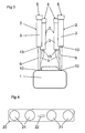
- the holding member 20 disclosed has four engagement portions 21 or openings for engaging a respective one of the teatcup liners 4, 5, see also Fig 4 , and a grip portion 22.
Abstract
Description
- The present invention refers to a set of a four of teatcup liners for a milking member including a claw and four teatcups to be attached to a respective teat of an animal to be milked, each teatcup liner having a liner portion adapted to be comprised in one of said teatcups and a conduit portion adapted to extend between the respective teatcup and the claw, wherein the conduit portion of each teatcup liner has at least one property influencing the operation of the teatcup liner during milking. The present invention also refers to a milking member including a claw, four teatcups and a set of a four of teatcup liners, each teatcup liner having a liner portion comprised in one of said teatcups and a conduit portion extending between the respective teatcup and the claw, wherein the conduit portion of each teatcup liner has at least one property influencing the operation of the teatcup liner during milking. Such a set and such a milking member is disclosed in
US-A-6,058,880 . - The positions of the teats of the udder of cows is in the most cases asymmetric or irregular. For instance, the distance between the two front teats is normally longer than the distance between the two rear teats. An investigation from 1983 discloses an average distance between the front teats of 150 mm, between the rear teats of 85 mm and between the rear and front teats of 100 mm. Furthermore, the front udder half is usually higher than the rear one, i.e. the two front teats are usually located at a higher position than the two rear teats. Moreover, when the udders are filled with milk the teats are relatively stiff and straggling. Therefore, the teats will be relatively immovable in relation to these positions.
- This situation makes it difficult to attach teatcups configured in a conventional manner to the teats of the cow, since the teatcups do not reach the teats properly. It may therefore be difficult to attach teatcups in such a manner that they close tightly against the teat. If the teatcup liner does not close tightly against the teat, there may be a significant air inlet between the teatcup liner and the teat, which may not be controlled. This deficiency makes the milking less effective and requires a higher capacity of the vacuum pump, which in certain situations can lead to detachment of the teatcups before the milking has been terminated. There is also a restricting requirement regarding the length of the conduit portions of the teatcup liners. If the conduit portions are too long, the claw will touch the ground or the floor, at least during the end of the milking. The problems mentioned above have become worse in recent time, since the short milk conduit has become thicker and thus stiffer in order to be able to conduct an increasing milk flow. Furthermore, it has been difficult to provide a close connection between the short milk conduit and the housing of the claw due to the bending forces acting on the milk conduit. Because of this, air tends to penetrate the inner space of the housing between the short milk conduit and the inlet opening.
-
US-A-6,058,880 discloses a milking member including a claw, four teatcups and a set of a four of teatcup liners. Each teatcup liner has a liner portion to be comprised in one of said teatcups and a conduit portion extending between the respective teatcup and the claw. The conduit portion of each teatcup liner is substantially identical to the conduit portion of the remaining teatcup liners. This document recognises the problem caused by the irregularity of the udder. In this document it is proposed to solve this problem by providing the claw with an asymmetrical shape. The distance between the forward inlet members is longer than the distance between the rear inlet members. Moreover, the forward inlet members are provided at a higher position than the rear inlet members. Finally, this document also discloses that the forward inlet members has a larger angle of inclination to a vertical central axis than the rear inlet members. -
DE-1 027 457 discloses a milking member including a claw with four inlet nipples. The two inlet nipples intended for the forward teats of the animal have a length which is shorter than the length of the inlet nipples intended for the rear teats of the animal. -
US-A-631,774 discloses a milking member of a different kind. The milking member has four teatcups attached to a central member via a respective rigid milk conduit. The milk conduits extend horizontally and have a length that is adjustable by means of a telescoping mechanism. -
US,A-2,497,299 discloses a milking device having a closure plate mounted to a receptacle. From the closure plate, four short milk conduits extend to a respective teatcup attached to a respective teat of an animal to be milked. Nothing is mentioned inUS-A-2,497,299 about differing properties of the short milk conduits. - The object of the present invention is to provide a solution to the problems discussed above.
- This object is achieved by the set of teatcup liners initially defined, which is characterised by the characterising features of
claim 1. - By means of such a configuration of the seat of teatcup liners, it may be ensured that the teatcups in a better way than previously reach their respective teats properly. The properties significally influence the operation of the milking member during the milking of the animal. The engagement or the grip between the teatcup liners and their respective teats may be improved, reducing the risk for air leakage. Furthermore, the tensions in the conduit portion may decrease and the claw will be suspended in more natural manner beneath the animal. In addition, such a configuration may also result in an equal, downwardly directed force, acting at each teat, for all four teats. Consequently, an equal and proper milk extraction of each teat may be guaranteed.
- Moreover, these advantages may be achieved by the use of a conventional claw being symmetrical with regard to the position, shape an design of the milk inlet members.
- According to an embodiment of the present invention, the first pair of said teatcup liners is adapted to be attached to the rear teats of the animal and the second pair of said teatcup liners is adapted to be attached to the forward teats of the animal.
- According to a further embodiment or the present invention, said property includes the length of the conduit portion, wherein the length of the first pair differs from the length of the second pair by a predetermined distance. By such a design, the claw will hang down in natural way beneath the udder without sloping in any direction. Preferably, the predetermined distance corresponds to the length difference between the rear teats and the forward teats of the animal, wherein the length of the first pair may be shorter than the length of the second pair.
- According to a further embodiment of the present invention said property includes the flexibility of the conduit portion, wherein the flexibility of the first pair differs from the flexibility of the second pair by a predetermined value. Such a differing flexibility is advantageous when the teats of one pair of teats are directed outwardly, since the differing flexibility permits all the teatcups to be tightly attached to the respective teat. Advantageously, the flexibility of the first pair is higher than the flexibility of the second pair.
- According to a further embodiment of the present invention, said property includes the straightness of the conduit portion, wherein the straightness of the first pair differs from the straightness of the second pair by a predetermined value. By such a pre-formed modification of the straightness of the conduit portion, the attachment of the milking member to the teats may be adapted in a better way to the shape of the udder. Preferably, the straightness of the first pair is higher than the straightness of the second pair. Furthermore, each conduit portion of the first pair of teatcups liners may advantageously have a slightly S-like curvature in such a way that the distance between the conduit portions at the upper end in the proximity of the teatcup is shorter than at the lower end in the proximity of the claw.
- According to a further embodiment of the present invention, each teatcup liner is one moulded piece. By moulding the teatcup liner in one single piece of material, the liner may be manufactured in an easy and convenient manner. A pre-formed straightness, e.g. a non-straight extension of the conduit portion, may easily be achieved by such a manufacturing method.
- According to a further embodiment of the present invention, the set includes a member for keeping the teatcup liners together prior to the mounting of the liners in the milking member.
- The object is also achieved by the milking member initially defined, which is characterised by the characterising features of
claim 13. Preferred embodiments of the milking member are defined in claims 14-23. - The present invention will now be described more closely by means of various embodiments thereof and with reference to the drawings attached hereto.
- Fig 1
- shows schematically a view of a set of teatcups liners according to a first embodiment of the present invention.
- Fig 2
- shows schematically a view of a set of teatcup liners according to a second embodiment of the present invention.
- Fig 3
- shows schematically a view of a milking member according to the present invention.
- Fig 4
- discloses schematically a view from above of a holding member for holding the set of teatcup liners.
-
Fig 3 discloses a milking member for the milking of an animal, e.g. a cow. The milking member includes aclaw 1 and fourteatcups 2. Eachteatcup 2 includes ateatcup shell 3 and ateatcup liner claw 1 may be of any conventional type, which has a housing forming an inner space for collecting the milk from each of theteatcups 2. The teatcup liners includes two pairs ofteatcup liners teatcup liners 4 and a second pair ofteatcup liners 5. In the embodiments disclosed, the first pair of theteatcup liners 4 is adapted to be attached to the rear teats of the animal to be milked, and the second pair of saidteatcup liners 5 is adapted to be attached to the forward teats of the animal. - Each
teatcup liner teatcup liner liner portion 8 and aconduit portion 9, seeFigs 1 and2 . Theliner portion 8 is comprised in a respective one of saidteatcups 2, and more precisely introduced in a respective one of theteatcup shells 3. When theteatcup 2 is attached to a teat of an animal to be milked, the teat is introduced into the interior of theliner portion 8 of theteatcup liner conduit portion 9 extends between theliner portion 8 and theclaw 1. Theconduit portion 9 thus has an upper end in the proximity of or adjoining theliner portion 8, and a lower end. The lower end is connected to an inlet member of theclaw 1. - In the embodiments disclosed, see
Fig 3 , the inlet member is formed by an aperture through the housing of theclaw 1, wherein the lower end of theconduit portion 9 is introduced into the aperture. The lower end includes tworibs conduit portion 9. Theribs conduit portion 9 is introduced in the aperture of theclaw 1, one of theribs 10 will abut the upper surface surrounding the aperture and theother rib 11 will abut the lower surface surrounding the aperture. It is to be noted that the inlet members also may be formed by tubular inlet nipples extending from theclaw 1, wherein each inlet nipple is introduced into the lower end of therespective conduit portion 9. - Furthermore, each
teatcup liner conduit portion 9 includes tworibs conduit portion 9. Theribs teatcup liner respective teatcup shell 3, theconduit portion 9 will extend through an opening in the lower part of theteatcup shell 3, wherein one of theribs 12 will abut an upper surface surrounding the opening and theother rib 13 will abut the lower surface surrounding the opening. - The
conduit portion 9 of eachteatcup liner teatcup liner different teatcup liners claw 1. In particular, said property of afirst pair 8 of the four teatcup liners differs in a predetermined manner from said property of a second pair of the fourteatcup liners - According to a first embodiment, disclosed in
Fig 1 , said property refers to the length of theconduit portion 9, i.e. the length of one of said pairs differs from the length of the other of said pair by apredetermined distance 14. In particular, the length of the first pair ofteatcup liners 4 to be attached to the rear teats is shorter than the length of the second pair ofteatcup liners 5 to be attached to the forward teats. Since the rear teats normally are lower than the forward teats, this embodiment permits theclaw 1 to hang down properly, i.e. without sloping in any direction. Preferably, thepredetermined distance 14 corresponds to an average length difference between the rear teats and the forward teats of an animal, for instance a cow. For instance, thedistance 14 may be at least 10 mm, at least 20 mm, at least 30 mm or at least 40 mm. - According to a second embodiment, said property refers to the flexibility of the
conduit portion 9, wherein the flexibility of the first pair ofteatcup liners 4 differs from the flexibility of the second pair ofteatcup liners 5 by a predetermined value. In particular, the flexibility of the first pair ofteatcup liners 4 to be attached to the rear teats of the animal is higher than the flexibility of the second pair ofteatcup liners 5 to be attached to the forward teats of the animal. - According to a third embodiment, disclosed in
Fig 2 , said property refers to the straightness of theconduit portion 9, wherein the straightness of the first pair ofteatcup liners 4 differs from the straightness of the second pair ofteatcup liners 5 by a predetermined value. In particular, the straightness of the second pair ofteatcup liners 5 to be attached to the forward teats of the animal is higher than the straightness of the first pair ofteatcup liners 4 to be attached to the rear teats of the animal. As disclosed inFigs 2 and3 , eachconduit portion 9 of the first pair ofteatcups liners 4 has a slightly S-like curvature in such a way that the distance between theconduit portions 9 of the first pair ofteatcup liners 4 at the upper end adjoining theliner portion 8 in the proximity of theteatcup shell 3 is shorter than at the lower end to be connected to theclaw 1. By such a non-straight extension it is possible to compensate for the shorter mutual distance between the rear teats than between the forward teats. Moreover, by such a non-straight extension it is also possible to compensate for the shorter distance between the pair of rear teats and the pair of forward teats than mutual distance between the two forward teats. - It is to be noted that the three property differences between the first pair of
teatcup liners 4 and second pair ofteatcup liners 5, which have been described above, may be combined with each other in all possible combinations. Thus the first pair may be shorter and more flexible than the second pair, shorter and less straight than the second pair, more flexible and less straight than the second pair, and/or shorter, more flexible and less straight than the second pair. - The four
teatcup liners respective teatcup shell 3 and attached to aclaw 2 of a milking member. The set ofteatcup liners teatcup liners member 20. The holdingmember 20 disclosed has fourengagement portions 21 or openings for engaging a respective one of theteatcup liners Fig 4 , and agrip portion 22. - The present invention is not limited to the embodiments disclosed and described herein, but may be varied and modified within the scope of the following claims.
Claims (23)
- A set of a four of teatcup liners (4, 5) for a milking member including a claw (1) and four teatcups (2) to be attached to a respective teat of an animal to be milked, each teatcup liner (4, 5) having a liner portion (8) adapted to be comprised in one of said teatcups (2) and a conduit portion (5) adapted to extend between the respective teatcup and the claw, wherein the conduit portion (9) of each teatcup liner has at least one property influencing the operation of the teatcup liner during milking, characterised in that said property of the conduit portion (9) of a first pair of the four teatcup liners (4) differs in a predetermined manner from said property of a second pair of the four teatcup liners (5), and that said property includes at least one of the length of the conduit portion (9), the flexibility of the conduit portion (9) and the straightness of the conduit portion (9).
- The set according to claim 1, characterised in that the first pair of said teatcup liners (4) is adapted to be attached to the rear teats of the animal and the second pair of said teatcup liners (5) is adapted to be attached to the forward teats of the animal.
- The set according to any one of the preceding claims, characterised in that said property includes the length of the conduit portion (9), wherein the length of the first pair differs from the length of the second pair by a predetermined distance (14).
- The set according to claim 3, characterised in that the predetermined distance (14) corresponds to the length difference between the rear teats and the forward teats of the animal.
- The set according to claim 4, characterised in the length of the first pair is shorter than the length of the second pair.
- The set according to any one of the preceding claims, characterised in that said property includes the flexibility of the conduit portion (9), wherein the flexibility of the first pair differs from the flexibility of the second pair by a predetermined value.
- The set according to claim 6, characterised in that the flexibility of the first pair is higher than the flexibility of the second pair.
- The set according to any one of the preceding claims, characterised in that said property includes the straightness of the conduit portion (9), wherein the straightness of the first pair differs from the straightness of the second pair by a predetermined value.
- The set according to claim 8, characterised in that the straightness of the second pair is higher than the straightness of the first pair.
- The set according to claim 9, characterised in that each conduit portion (9) of the first pair of teatcups liners (4) has a slightly S-like curvature in such a way that the distance between the conduit portions (9) at the upper end in the proximity of the teatcup (2) is shorter than at the lower end in the proximity of the claw (1).
- The set according to any one of the preceding claims, characterised in that each teatcup liner (4, 5) is one moulded piece.
- The set according to any one of the preceding claims, characterised in that the set includes a member (20) for keeping the teatcup liners (4, 5) together prior to the mounting of the liners in the milking member.
- A milking member including a claw (1), four teatcups (2) and a set of a four of teatcup liners (4, 5) each teatcup liner (4, 5) having a liner portion (8) comprised in one of said teatcups (2) and a conduit portion (9) extending between the respective teatcup (2) and the claw (1), wherein the conduit portion (9) of each teatcup (4, 5) has at least one property influencing the operation of the teatcup liner during milking, characterised in that said property of a first pair of the four teatcup liners (4) differs in a predetermined manner from said property of a second pair of the four teatcup liners (5), and that said property includes at least one of the length of the conduit portion (9), the flexibility of the conduit portion (9) and the straightness of the conduit portion (9).
- The milking member according to claim 13, characterised in that the first pair of said teatcup liners (4) is adapted to be attached to the rear teats of the animal and the second pair of said teatcup liners (5) is adapted to be attached to the forward teats of the animal.
- The milking member according to any one of claims 13 and 14, characterised in that said property includes the length of the conduit portion (9), wherein the length of the first pair differs from the length of the second pair by a predetermined distance (14).
- The milking member according to claim 15, characterised in that the predetermined distance (14) corresponds to the length difference between the rear teats and the forward teats of the animal.
- The milking member according to claim 16, characterised in the length of the first pair is shorter than the length of the second pair.
- The milking member according to any one of claims 13 to 17, characterised in that said property includes the flexibility of the conduit portion (9), wherein the flexibility of the first pair differs from the flexibility of the second pair by a predetermined value.
- The milking member according to claim 18, characterised in that the flexibility of the first pair is higher than the flexibility of the second pair.
- The milking member according to any one of claims 13 to 19, characterised in that said property includes the straightness of the conduit portion (9), wherein the straightness of the first pair differs from the straightness of the second pair by a predetermined value.
- The milking member according to claim 20, characterised in that the straightness of the second pair is higher than the straightness of the first pair.
- The milking member according to claim 21, characterised in that each conduit portion of the first pair of teatcups liners (4) has a slightly S-like curvature in such a way that the distance between the conduit portions (9) at the upper end in the proximity of the teatcup (2) is shorter than at the lower end in the proximity of the claw (1).
- The milking member according to any one of claims 13 to 22, characterised in that each teatcup liner (4, 5) is one moulded piece.
Applications Claiming Priority (3)
| Application Number | Priority Date | Filing Date | Title |
|---|---|---|---|
| SE0300892 | 2003-03-28 | ||
| SE0300892A SE0300892D0 (en) | 2003-03-28 | 2003-03-28 | A set of teatcups, and a milking member |
| PCT/SE2004/000424 WO2004084622A1 (en) | 2003-03-28 | 2004-03-22 | A set of teatcups, and a milking member |
Publications (2)
| Publication Number | Publication Date |
|---|---|
| EP1608217A1 EP1608217A1 (en) | 2005-12-28 |
| EP1608217B1 true EP1608217B1 (en) | 2008-03-19 |
Family
ID=20290841
Family Applications (1)
| Application Number | Title | Priority Date | Filing Date |
|---|---|---|---|
| EP04722489A Revoked EP1608217B1 (en) | 2003-03-28 | 2004-03-22 | A set of teatcups, and a milking member |
Country Status (6)
| Country | Link |
|---|---|
| US (1) | US20060219180A1 (en) |
| EP (1) | EP1608217B1 (en) |
| AT (1) | ATE389323T1 (en) |
| DE (1) | DE602004012536D1 (en) |
| SE (1) | SE0300892D0 (en) |
| WO (1) | WO2004084622A1 (en) |
Families Citing this family (5)
| Publication number | Priority date | Publication date | Assignee | Title |
|---|---|---|---|---|
| US11006613B2 (en) * | 2015-09-21 | 2021-05-18 | Afimilk Agricultural Cooperative Ltd. | Mobile milking robot with minimal footprint |
| US11019801B2 (en) | 2015-09-21 | 2021-06-01 | Afimilk Agricultural Cooperative Ltd. | Multiple cell voluntary milking method and system, comprising a mobile milking robot having a minimal footprint |
| US9980457B2 (en) | 2016-08-17 | 2018-05-29 | Technologies Holdings Corp. | Vision system with teat candidate identification |
| US10477827B2 (en) | 2016-08-17 | 2019-11-19 | Technologies Holdings Corp. | Vision system for teat detection |
| US9807971B1 (en) | 2016-08-17 | 2017-11-07 | Technologies Holdings Corp. | Vision system with automatic teat detection |
Family Cites Families (13)
| Publication number | Priority date | Publication date | Assignee | Title |
|---|---|---|---|---|
| US631774A (en) * | 1898-12-08 | 1899-08-29 | Charles C Bundy | Milking-machine. |
| US678231A (en) * | 1899-06-17 | 1901-07-09 | Clemens Von Bechtolsheim | Pneumatic or hydraulic milking apparatus. |
| US2429983A (en) * | 1942-06-12 | 1947-11-04 | Universal Milking Machine Comp | Milking apparatus |
| US2497299A (en) * | 1947-05-03 | 1950-02-14 | Int Harvester Co | Supporting means for milking apparatus |
| DE1027457B (en) * | 1956-10-17 | 1958-04-03 | Utina Elektrowerk Gmbh | Milk claws for milking machines |
| US3079891A (en) * | 1960-07-25 | 1963-03-05 | Bernard F Miller | Milking cup assembly |
| US3818866A (en) * | 1967-08-28 | 1974-06-25 | Babso Bros Co | Milker |
| US3999516A (en) * | 1975-06-13 | 1976-12-28 | Babson Brothers Company | Milker with resilient pulsator manifold mounting |
| SE8803462L (en) * | 1988-09-29 | 1990-03-30 | Alfa Laval Agri Int | PLATE PACKAGING FOR THE EXTRA GUM |
| WO1997027736A1 (en) * | 1996-02-05 | 1997-08-07 | Alfa Laval Agri Ab | A claw for a milking machine |
| SE9600413L (en) * | 1996-02-05 | 1997-06-09 | Alfa Laval Agri Ab | Spenkoppscental |
| DE19922131C1 (en) * | 1999-05-12 | 2001-03-01 | Jakob Maier | Flexible milk hose for an automatic milking system |
| US6742475B1 (en) * | 2002-12-18 | 2004-06-01 | Delaval Holding Ab | Variable shut off teat cup liner |
-
2003
- 2003-03-28 SE SE0300892A patent/SE0300892D0/en unknown
-
2004
- 2004-03-22 DE DE602004012536T patent/DE602004012536D1/en not_active Expired - Lifetime
- 2004-03-22 AT AT04722489T patent/ATE389323T1/en not_active IP Right Cessation
- 2004-03-22 EP EP04722489A patent/EP1608217B1/en not_active Revoked
- 2004-03-22 WO PCT/SE2004/000424 patent/WO2004084622A1/en active Application Filing
- 2004-03-22 US US10/550,983 patent/US20060219180A1/en not_active Abandoned
Also Published As
| Publication number | Publication date |
|---|---|
| US20060219180A1 (en) | 2006-10-05 |
| ATE389323T1 (en) | 2008-04-15 |
| WO2004084622A1 (en) | 2004-10-07 |
| EP1608217A1 (en) | 2005-12-28 |
| DE602004012536D1 (en) | 2008-04-30 |
| SE0300892D0 (en) | 2003-03-28 |
Similar Documents
| Publication | Publication Date | Title |
|---|---|---|
| US5493995A (en) | Collapsing teat cup liner with tapering barrel wall | |
| US6895892B2 (en) | Short milk tube | |
| US10785952B2 (en) | Short milk tube with protective vent for a dairy animal milker unit | |
| US7921806B2 (en) | Teatcup, and a teatcup part | |
| EP0734648B1 (en) | Milking cluster air fork | |
| EP1138193A2 (en) | An implement for milking animals | |
| JP3952085B2 (en) | Milking machine claw | |
| US4807566A (en) | Milk claw | |
| US6588364B1 (en) | Teatcup liner, a teatcup including a teatcup liner, and a milking member | |
| US20070272160A1 (en) | Modified milk-collecting component | |
| US6532893B1 (en) | Device arranged to carry a set of teatcups | |
| US3726252A (en) | Automatic milker | |
| EP1608217B1 (en) | A set of teatcups, and a milking member | |
| US20060254524A1 (en) | Milking claw | |
| EP0880888A3 (en) | An implement for automatically milking animals | |
| EP0347954B1 (en) | An implement for milking animals, such as cows | |
| US3643630A (en) | Inflation tube connection | |
| US5855183A (en) | Teat cup assembly | |
| EP0908091A1 (en) | A teat cup lining to be applied in a teat cup for milking animals | |
| EP3262927B1 (en) | Short milk tube and method of using the same | |
| SE515746C2 (en) | Liner for a teat cup comprises a curved head which in cross section has the radius of one side made greater than that of the opposite side,with a central aperture to receive the animals teat | |
| SE515745C2 (en) | Liner for a teat cup comprises a curved head which in cross section has the radius of one side made greater than that of the opposite side,with a central aperture to receive the animals teat | |
| CA2295630A1 (en) | A teat cup and a milking robot comprising same | |
| KR20130018530A (en) | Gripping device for a milking unit |
Legal Events
| Date | Code | Title | Description |
|---|---|---|---|
| PUAI | Public reference made under article 153(3) epc to a published international application that has entered the european phase |
Free format text: ORIGINAL CODE: 0009012 |
|
| 17P | Request for examination filed |
Effective date: 20050921 |
|
| AK | Designated contracting states |
Kind code of ref document: A1 Designated state(s): AT BE BG CH CY CZ DE DK EE ES FI FR GB GR HU IE IT LI LU MC NL PL PT RO SE SI SK TR |
|
| AX | Request for extension of the european patent |
Extension state: AL LT LV MK |
|
| DAX | Request for extension of the european patent (deleted) | ||
| 17Q | First examination report despatched |
Effective date: 20061207 |
|
| GRAP | Despatch of communication of intention to grant a patent |
Free format text: ORIGINAL CODE: EPIDOSNIGR1 |
|
| GRAS | Grant fee paid |
Free format text: ORIGINAL CODE: EPIDOSNIGR3 |
|
| GRAA | (expected) grant |
Free format text: ORIGINAL CODE: 0009210 |
|
| AK | Designated contracting states |
Kind code of ref document: B1 Designated state(s): AT BE BG CH CY CZ DE DK EE ES FI FR GB GR HU IE IT LI LU MC NL PL PT RO SE SI SK TR |
|
| REG | Reference to a national code |
Ref country code: GB Ref legal event code: FG4D |
|
| REG | Reference to a national code |
Ref country code: CH Ref legal event code: EP |
|
| REF | Corresponds to: |
Ref document number: 602004012536 Country of ref document: DE Date of ref document: 20080430 Kind code of ref document: P |
|
| REG | Reference to a national code |
Ref country code: IE Ref legal event code: FG4D |
|
| PG25 | Lapsed in a contracting state [announced via postgrant information from national office to epo] |
Ref country code: FI Free format text: LAPSE BECAUSE OF FAILURE TO SUBMIT A TRANSLATION OF THE DESCRIPTION OR TO PAY THE FEE WITHIN THE PRESCRIBED TIME-LIMIT Effective date: 20080319 |
|
| PG25 | Lapsed in a contracting state [announced via postgrant information from national office to epo] |
Ref country code: AT Free format text: LAPSE BECAUSE OF FAILURE TO SUBMIT A TRANSLATION OF THE DESCRIPTION OR TO PAY THE FEE WITHIN THE PRESCRIBED TIME-LIMIT Effective date: 20080319 |
|
| NLV1 | Nl: lapsed or annulled due to failure to fulfill the requirements of art. 29p and 29m of the patents act | ||
| PG25 | Lapsed in a contracting state [announced via postgrant information from national office to epo] |
Ref country code: BE Free format text: LAPSE BECAUSE OF FAILURE TO SUBMIT A TRANSLATION OF THE DESCRIPTION OR TO PAY THE FEE WITHIN THE PRESCRIBED TIME-LIMIT Effective date: 20080319 Ref country code: SI Free format text: LAPSE BECAUSE OF FAILURE TO SUBMIT A TRANSLATION OF THE DESCRIPTION OR TO PAY THE FEE WITHIN THE PRESCRIBED TIME-LIMIT Effective date: 20080319 Ref country code: PL Free format text: LAPSE BECAUSE OF FAILURE TO SUBMIT A TRANSLATION OF THE DESCRIPTION OR TO PAY THE FEE WITHIN THE PRESCRIBED TIME-LIMIT Effective date: 20080319 |
|
| PG25 | Lapsed in a contracting state [announced via postgrant information from national office to epo] |
Ref country code: PT Free format text: LAPSE BECAUSE OF FAILURE TO SUBMIT A TRANSLATION OF THE DESCRIPTION OR TO PAY THE FEE WITHIN THE PRESCRIBED TIME-LIMIT Effective date: 20080826 Ref country code: CZ Free format text: LAPSE BECAUSE OF FAILURE TO SUBMIT A TRANSLATION OF THE DESCRIPTION OR TO PAY THE FEE WITHIN THE PRESCRIBED TIME-LIMIT Effective date: 20080319 Ref country code: SK Free format text: LAPSE BECAUSE OF FAILURE TO SUBMIT A TRANSLATION OF THE DESCRIPTION OR TO PAY THE FEE WITHIN THE PRESCRIBED TIME-LIMIT Effective date: 20080319 Ref country code: ES Free format text: LAPSE BECAUSE OF FAILURE TO SUBMIT A TRANSLATION OF THE DESCRIPTION OR TO PAY THE FEE WITHIN THE PRESCRIBED TIME-LIMIT Effective date: 20080630 Ref country code: DE Free format text: LAPSE BECAUSE OF FAILURE TO SUBMIT A TRANSLATION OF THE DESCRIPTION OR TO PAY THE FEE WITHIN THE PRESCRIBED TIME-LIMIT Effective date: 20080620 Ref country code: MC Free format text: LAPSE BECAUSE OF NON-PAYMENT OF DUE FEES Effective date: 20080331 Ref country code: SE Free format text: LAPSE BECAUSE OF FAILURE TO SUBMIT A TRANSLATION OF THE DESCRIPTION OR TO PAY THE FEE WITHIN THE PRESCRIBED TIME-LIMIT Effective date: 20080619 |
|
| REG | Reference to a national code |
Ref country code: CH Ref legal event code: PL |
|
| PG25 | Lapsed in a contracting state [announced via postgrant information from national office to epo] |
Ref country code: RO Free format text: LAPSE BECAUSE OF FAILURE TO SUBMIT A TRANSLATION OF THE DESCRIPTION OR TO PAY THE FEE WITHIN THE PRESCRIBED TIME-LIMIT Effective date: 20080319 Ref country code: NL Free format text: LAPSE BECAUSE OF FAILURE TO SUBMIT A TRANSLATION OF THE DESCRIPTION OR TO PAY THE FEE WITHIN THE PRESCRIBED TIME-LIMIT Effective date: 20080319 |
|
| PGFP | Annual fee paid to national office [announced via postgrant information from national office to epo] |
Ref country code: FR Payment date: 20080417 Year of fee payment: 5 |
|
| PLBI | Opposition filed |
Free format text: ORIGINAL CODE: 0009260 |
|
| EN | Fr: translation not filed | ||
| PLAX | Notice of opposition and request to file observation + time limit sent |
Free format text: ORIGINAL CODE: EPIDOSNOBS2 |
|
| PG25 | Lapsed in a contracting state [announced via postgrant information from national office to epo] |
Ref country code: CH Free format text: LAPSE BECAUSE OF NON-PAYMENT OF DUE FEES Effective date: 20080331 Ref country code: IE Free format text: LAPSE BECAUSE OF NON-PAYMENT OF DUE FEES Effective date: 20080325 Ref country code: EE Free format text: LAPSE BECAUSE OF FAILURE TO SUBMIT A TRANSLATION OF THE DESCRIPTION OR TO PAY THE FEE WITHIN THE PRESCRIBED TIME-LIMIT Effective date: 20080319 Ref country code: DK Free format text: LAPSE BECAUSE OF FAILURE TO SUBMIT A TRANSLATION OF THE DESCRIPTION OR TO PAY THE FEE WITHIN THE PRESCRIBED TIME-LIMIT Effective date: 20080319 Ref country code: LI Free format text: LAPSE BECAUSE OF NON-PAYMENT OF DUE FEES Effective date: 20080331 |
|
| 26 | Opposition filed |
Opponent name: GEA WESTFALIASURGE GMBH Effective date: 20081219 |
|
| GBPC | Gb: european patent ceased through non-payment of renewal fee |
Effective date: 20080619 |
|
| PG25 | Lapsed in a contracting state [announced via postgrant information from national office to epo] |
Ref country code: BG Free format text: LAPSE BECAUSE OF FAILURE TO SUBMIT A TRANSLATION OF THE DESCRIPTION OR TO PAY THE FEE WITHIN THE PRESCRIBED TIME-LIMIT Effective date: 20080619 |
|
| PG25 | Lapsed in a contracting state [announced via postgrant information from national office to epo] |
Ref country code: GB Free format text: LAPSE BECAUSE OF NON-PAYMENT OF DUE FEES Effective date: 20080619 |
|
| PG25 | Lapsed in a contracting state [announced via postgrant information from national office to epo] |
Ref country code: IT Free format text: LAPSE BECAUSE OF FAILURE TO SUBMIT A TRANSLATION OF THE DESCRIPTION OR TO PAY THE FEE WITHIN THE PRESCRIBED TIME-LIMIT Effective date: 20080319 |
|
| PG25 | Lapsed in a contracting state [announced via postgrant information from national office to epo] |
Ref country code: CY Free format text: LAPSE BECAUSE OF FAILURE TO SUBMIT A TRANSLATION OF THE DESCRIPTION OR TO PAY THE FEE WITHIN THE PRESCRIBED TIME-LIMIT Effective date: 20080319 |
|
| PG25 | Lapsed in a contracting state [announced via postgrant information from national office to epo] |
Ref country code: HU Free format text: LAPSE BECAUSE OF FAILURE TO SUBMIT A TRANSLATION OF THE DESCRIPTION OR TO PAY THE FEE WITHIN THE PRESCRIBED TIME-LIMIT Effective date: 20080920 Ref country code: LU Free format text: LAPSE BECAUSE OF NON-PAYMENT OF DUE FEES Effective date: 20080322 |
|
| PG25 | Lapsed in a contracting state [announced via postgrant information from national office to epo] |
Ref country code: TR Free format text: LAPSE BECAUSE OF FAILURE TO SUBMIT A TRANSLATION OF THE DESCRIPTION OR TO PAY THE FEE WITHIN THE PRESCRIBED TIME-LIMIT Effective date: 20080319 |
|
| PG25 | Lapsed in a contracting state [announced via postgrant information from national office to epo] |
Ref country code: GR Free format text: LAPSE BECAUSE OF FAILURE TO SUBMIT A TRANSLATION OF THE DESCRIPTION OR TO PAY THE FEE WITHIN THE PRESCRIBED TIME-LIMIT Effective date: 20080620 |
|
| RDAF | Communication despatched that patent is revoked |
Free format text: ORIGINAL CODE: EPIDOSNREV1 |
|
| RDAG | Patent revoked |
Free format text: ORIGINAL CODE: 0009271 |
|
| STAA | Information on the status of an ep patent application or granted ep patent |
Free format text: STATUS: PATENT REVOKED |
|
| 27W | Patent revoked |
Effective date: 20110715 |