EP1608217B1 - Ensemble de gobelets trayeurs et element de traite - Google Patents
Ensemble de gobelets trayeurs et element de traite Download PDFInfo
- Publication number
- EP1608217B1 EP1608217B1 EP04722489A EP04722489A EP1608217B1 EP 1608217 B1 EP1608217 B1 EP 1608217B1 EP 04722489 A EP04722489 A EP 04722489A EP 04722489 A EP04722489 A EP 04722489A EP 1608217 B1 EP1608217 B1 EP 1608217B1
- Authority
- EP
- European Patent Office
- Prior art keywords
- pair
- teatcup
- conduit portion
- liners
- length
- Prior art date
- Legal status (The legal status is an assumption and is not a legal conclusion. Google has not performed a legal analysis and makes no representation as to the accuracy of the status listed.)
- Revoked
Links
Images

Classifications
-
- A—HUMAN NECESSITIES
- A01—AGRICULTURE; FORESTRY; ANIMAL HUSBANDRY; HUNTING; TRAPPING; FISHING
- A01J—MANUFACTURE OF DAIRY PRODUCTS
- A01J5/00—Milking machines or devices
- A01J5/04—Milking machines or devices with pneumatic manipulation of teats
- A01J5/08—Teat-cups with two chambers
-
- A—HUMAN NECESSITIES
- A01—AGRICULTURE; FORESTRY; ANIMAL HUSBANDRY; HUNTING; TRAPPING; FISHING
- A01J—MANUFACTURE OF DAIRY PRODUCTS
- A01J5/00—Milking machines or devices
- A01J5/04—Milking machines or devices with pneumatic manipulation of teats
-
- A—HUMAN NECESSITIES
- A01—AGRICULTURE; FORESTRY; ANIMAL HUSBANDRY; HUNTING; TRAPPING; FISHING
- A01J—MANUFACTURE OF DAIRY PRODUCTS
- A01J5/00—Milking machines or devices
- A01J5/04—Milking machines or devices with pneumatic manipulation of teats
- A01J5/044—Milk lines or coupling devices for milk conduits
Definitions
- the present invention refers to a set of a four of teatcup liners for a milking member including a claw and four teatcups to be attached to a respective teat of an animal to be milked, each teatcup liner having a liner portion adapted to be comprised in one of said teatcups and a conduit portion adapted to extend between the respective teatcup and the claw, wherein the conduit portion of each teatcup liner has at least one property influencing the operation of the teatcup liner during milking.
- the present invention also refers to a milking member including a claw, four teatcups and a set of a four of teatcup liners, each teatcup liner having a liner portion comprised in one of said teatcups and a conduit portion extending between the respective teatcup and the claw, wherein the conduit portion of each teatcup liner has at least one property influencing the operation of the teatcup liner during milking.
- a milking member including a claw, four teatcups and a set of a four of teatcup liners, each teatcup liner having a liner portion comprised in one of said teatcups and a conduit portion extending between the respective teatcup and the claw, wherein the conduit portion of each teatcup liner has at least one property influencing the operation of the teatcup liner during milking.
- the positions of the teats of the udder of cows is in the most cases asymmetric or irregular.
- the distance between the two front teats is normally longer than the distance between the two rear teats.
- An investigation from 1983 discloses an average distance between the front teats of 150 mm, between the rear teats of 85 mm and between the rear and front teats of 100 mm.
- the front udder half is usually higher than the rear one, i.e. the two front teats are usually located at a higher position than the two rear teats.
- the teats are relatively stiff and straggling. Therefore, the teats will be relatively immovable in relation to these positions.
- US-A-6,058,880 discloses a milking member including a claw, four teatcups and a set of a four of teatcup liners.
- Each teatcup liner has a liner portion to be comprised in one of said teatcups and a conduit portion extending between the respective teatcup and the claw.
- the conduit portion of each teatcup liner is substantially identical to the conduit portion of the remaining teatcup liners.
- DE-1 027 457 discloses a milking member including a claw with four inlet nipples.
- the two inlet nipples intended for the forward teats of the animal have a length which is shorter than the length of the inlet nipples intended for the rear teats of the animal.
- US-A-631,774 discloses a milking member of a different kind.
- the milking member has four teatcups attached to a central member via a respective rigid milk conduit.
- the milk conduits extend horizontally and have a length that is adjustable by means of a telescoping mechanism.
- US,A-2,497,299 discloses a milking device having a closure plate mounted to a receptacle. From the closure plate, four short milk conduits extend to a respective teatcup attached to a respective teat of an animal to be milked. None is mentioned in US-A-2,497,299 about differing properties of the short milk conduits.
- the object of the present invention is to provide a solution to the problems discussed above.
- the first pair of said teatcup liners is adapted to be attached to the rear teats of the animal and the second pair of said teatcup liners is adapted to be attached to the forward teats of the animal.
- said property includes the length of the conduit portion, wherein the length of the first pair differs from the length of the second pair by a predetermined distance.
- the predetermined distance corresponds to the length difference between the rear teats and the forward teats of the animal, wherein the length of the first pair may be shorter than the length of the second pair.
- said property includes the flexibility of the conduit portion, wherein the flexibility of the first pair differs from the flexibility of the second pair by a predetermined value.
- a differing flexibility is advantageous when the teats of one pair of teats are directed outwardly, since the differing flexibility permits all the teatcups to be tightly attached to the respective teat.
- the flexibility of the first pair is higher than the flexibility of the second pair.
- said property includes the straightness of the conduit portion, wherein the straightness of the first pair differs from the straightness of the second pair by a predetermined value.
- the attachment of the milking member to the teats may be adapted in a better way to the shape of the udder.
- the straightness of the first pair is higher than the straightness of the second pair.
- each conduit portion of the first pair of teatcups liners may advantageously have a slightly S-like curvature in such a way that the distance between the conduit portions at the upper end in the proximity of the teatcup is shorter than at the lower end in the proximity of the claw.
- each teatcup liner is one moulded piece.
- the liner may be manufactured in an easy and convenient manner.
- a pre-formed straightness, e.g. a non-straight extension of the conduit portion, may easily be achieved by such a manufacturing method.
- the set includes a member for keeping the teatcup liners together prior to the mounting of the liners in the milking member.
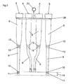
- Fig 3 discloses a milking member for the milking of an animal, e.g. a cow.
- the milking member includes a claw 1 and four teatcups 2.
- Each teatcup 2 includes a teatcup shell 3 and a teatcup liner 4, 5.
- the claw 1 may be of any conventional type, which has a housing forming an inner space for collecting the milk from each of the teatcups 2.
- the teatcup liners includes two pairs of teatcup liners 4, 5, a first pair of teatcup liners 4 and a second pair of teatcup liners 5.
- the first pair of the teatcup liners 4 is adapted to be attached to the rear teats of the animal to be milked
- the second pair of said teatcup liners 5 is adapted to be attached to the forward teats of the animal.
- Each teatcup liner 4, 5 is moulded in one piece of a rubber material to have a pre-formed shape.
- Each teatcup liner 4, 5 has a liner portion 8 and a conduit portion 9, see Figs 1 and 2 .
- the liner portion 8 is comprised in a respective one of said teatcups 2, and more precisely introduced in a respective one of the teatcup shells 3.
- the conduit portion 9 extends between the liner portion 8 and the claw 1.
- the conduit portion 9 thus has an upper end in the proximity of or adjoining the liner portion 8, and a lower end. The lower end is connected to an inlet member of the claw 1.
- the inlet member is formed by an aperture through the housing of the claw 1, wherein the lower end of the conduit portion 9 is introduced into the aperture.
- the lower end includes two ribs 10, 11 extending around the conduit portion 9.
- the ribs 10, 11 are positioned at a distance from each other.
- the inlet members also may be formed by tubular inlet nipples extending from the claw 1, wherein each inlet nipple is introduced into the lower end of the respective conduit portion 9.
- each teatcup liner 4, 5 in the proximity of the upper end of the conduit portion 9 includes two ribs 12, 13 extending around the conduit portion 9.
- the ribs 12, 13 are positioned at a distance from each other.
- each teatcup liner 4, 5 has at least one property influencing the operation of the teatcup liner 4, 5 during milking in a significant manner. More precisely, three different properties are exemplified in this application. In order to achieve an improved functioning of the milking member one, two or all of these properties are varied in a predetermined manner for the different teatcup liners 4, 5 in the set of liners to cooperate with the claw 1. In particular, said property of a first pair 8 of the four teatcup liners differs in a predetermined manner from said property of a second pair of the four teatcup liners 4, 5.
- said property refers to the length of the conduit portion 9, i.e. the length of one of said pairs differs from the length of the other of said pair by a predetermined distance 14.
- the length of the first pair of teatcup liners 4 to be attached to the rear teats is shorter than the length of the second pair of teatcup liners 5 to be attached to the forward teats. Since the rear teats normally are lower than the forward teats, this embodiment permits the claw 1 to hang down properly, i.e. without sloping in any direction.
- the predetermined distance 14 corresponds to an average length difference between the rear teats and the forward teats of an animal, for instance a cow.
- the distance 14 may be at least 10 mm, at least 20 mm, at least 30 mm or at least 40 mm.
- said property refers to the flexibility of the conduit portion 9, wherein the flexibility of the first pair of teatcup liners 4 differs from the flexibility of the second pair of teatcup liners 5 by a predetermined value.
- the flexibility of the first pair of teatcup liners 4 to be attached to the rear teats of the animal is higher than the flexibility of the second pair of teatcup liners 5 to be attached to the forward teats of the animal.
- said property refers to the straightness of the conduit portion 9, wherein the straightness of the first pair of teatcup liners 4 differs from the straightness of the second pair of teatcup liners 5 by a predetermined value.
- the straightness of the second pair of teatcup liners 5 to be attached to the forward teats of the animal is higher than the straightness of the first pair of teatcup liners 4 to be attached to the rear teats of the animal.
- each conduit portion 9 of the first pair of teatcups liners 4 has a slightly S-like curvature in such a way that the distance between the conduit portions 9 of the first pair of teatcup liners 4 at the upper end adjoining the liner portion 8 in the proximity of the teatcup shell 3 is shorter than at the lower end to be connected to the claw 1.
- first pair of teatcup liners 4 and second pair of teatcup liners 5 may be combined with each other in all possible combinations.
- first pair may be shorter and more flexible than the second pair, shorter and less straight than the second pair, more flexible and less straight than the second pair, and/or shorter, more flexible and less straight than the second pair.
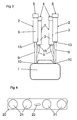
- the four teatcup liners 4, 5 form a set of teatcup liners to be mounted in a respective teatcup shell 3 and attached to a claw 2 of a milking member.
- the set of teatcup liners 4, 5 may be sold and distributed to a milk farmer as one unit.
- the teatcup liners 4, 5 of the set may be kept together in a package by a member, e.g. a holding member 20.
- the holding member 20 disclosed has four engagement portions 21 or openings for engaging a respective one of the teatcup liners 4, 5, see also Fig 4 , and a grip portion 22.
Landscapes
- Life Sciences & Earth Sciences (AREA)
- Animal Husbandry (AREA)
- Environmental Sciences (AREA)
- External Artificial Organs (AREA)
- Gas Separation By Absorption (AREA)
- Absorbent Articles And Supports Therefor (AREA)
- Adhesives Or Adhesive Processes (AREA)
Claims (23)
- Ensemble de quatre manchons-trayeurs (4, 5) pour élément de traite comprenant une griffe (1) et quatre gobelets-trayeurs (2) destinés à être fixés à un trayon respectif d'un animal à traire, chaque manchon-trayeur (4, 5) ayant une partie manchon (8) adaptée pour être comprise dans l'un desdits gobelets-trayeurs (2) et une partie tuyau (5) adaptée pour s'étendre entre le gobelet-trayeur respectif et la griffe, la partie tuyau (9) de chaque manchon-trayeur ayant au moins une propriété influençant le fonctionnement du manchon-trayeur pendant la traite, caractérisé en ce que ladite propriété de la partie tuyau (9) d'une première paire des quatre manchons-trayeurs (4) diffère d'une manière prédéterminée de ladite propriété d'une deuxième paire des quatre manchons-trayeurs (5), et en ce que ladite propriété comprend au moins une propriété parmi la longueur de la partie tuyau (9), la souplesse de la partie tuyau (9) et la rectitude de la partie tuyau (9).
- Ensemble selon la revendication 1, caractérisé en ce que la première paire desdits manchons-trayeurs (4) est adaptée pour être fixée aux trayons arrière de l'animal et la deuxième paire desdits manchons-trayeurs (5) est adaptée pour être fixée aux trayons avant de l'animal.
- Ensemble selon l'une quelconque des revendications précédentes, caractérisé en ce que ladite propriété comprend la longueur de la partie tuyau (9), la longueur de la première paire différant de la longueur de la deuxième paire d'une distance prédéterminée (14).
- Ensemble selon la revendication 3, caractérisé en ce que la distance prédéterminée (14) correspond à la différence de longueur entre les trayons arrière et les trayons avant de l'animal.
- Ensemble selon la revendication 4, caractérisé en ce que la longueur de la première paire est inférieure à la longueur de la deuxième paire.
- Ensemble selon l'une quelconque des revendications précédentes, caractérisé en ce que ladite propriété comprend la souplesse de la partie tuyau (9), la souplesse de la première paire différant de la souplesse de la deuxième paire d'une valeur prédéterminée.
- Ensemble selon la revendication 6, caractérisé en ce que la souplesse de la première paire est supérieure à la souplesse de la deuxième paire.
- Ensemble selon l'une quelconque des revendications précédentes, caractérisé en ce que ladite propriété comprend la rectitude de la partie tuyau (9), la rectitude de la première paire différant de la rectitude de la deuxième paire d'une valeur prédéterminée.
- Ensemble selon la revendication 8, caractérisé en ce que la rectitude de la deuxième paire est supérieure à la rectitude de la première paire.
- Ensemble selon la revendication 9, caractérisé en ce que chaque partie tuyau (9) de la première paire de manchons-trayeurs (4) a une légère courbure en S, de telle manière que la distance qui sépare les parties tuyau (9) à l'extrémité supérieure au voisinage du gobelet-trayeur (2) est plus petite qu'à l'extrémité inférieure au voisinage de la griffe (1).
- Ensemble selon l'une quelconque des revendications précédentes, caractérisé en ce que chaque manchon-trayeur (4, 5) est formé d'une pièce moulée.
- Ensemble selon l'une quelconque des revendications précédentes, caractérisé en ce que l'ensemble comprend un élément (20) pour maintenir les manchons-trayeurs (4, 5) groupés avant le montage des manchons dans l'élément de traite.
- Elément de traite comprenant une griffe (1), quatre gobelets-trayeurs (2) et un ensemble de quatre manchons-trayeurs (4, 5), chaque manchon-trayeur (4, 5) ayant une partie manchon (8) comprise dans l'un desdits gobelets-trayeurs (2) et une partie tuyau (9) s'étendant entre le gobelet-trayeur (2) respectif et la griffe (1), la partie tuyau (9) de chaque manchon-trayeur (4, 5) ayant au moins une propriété influençant le fonctionnement du manchon-trayeur pendant la traite, caractérisé en ce que ladite propriété d'une première paire des quatre manchons-trayeurs (4) diffère d'une manière prédéterminée de ladite propriété d'une deuxième paire des quatre manchons-trayeurs (5), et en ce que ladite propriété comprend au moins une propriété parmi la longueur de la partie tuyau (9), la souplesse de la partie tuyau (9) et la rectitude de la partie tuyau (9).
- Elément de traite selon la revendication 13, caractérisé en ce que la première paire desdits manchons-trayeurs (4) est adaptée pour être fixée aux trayons arrière de l'animal et la deuxième paire desdits manchons-trayeurs (5) est adaptée pour être fixée aux trayons avant de l'animal.
- Elément de traite selon la revendication 13 ou 14, caractérisé en ce que ladite propriété comprend la longueur de la partie tuyau (9), la longueur de la première paire différant de la longueur de la deuxième paire d'une distance prédéterminée (14).
- Elément de traite selon la revendication 15, caractérisé en ce que la distance prédéterminée (14) correspond à la différence de longueur entre les trayons arrière et les trayons avant de l'animal.
- Elément de traite selon la revendication 16, caractérisé en ce que la longueur de la première paire est inférieure à la longueur de la deuxième paire.
- Elément de traite selon l'une quelconque des revendications 13 à 17, caractérisé en ce que ladite propriété comprend la souplesse de la partie tuyau (9), la souplesse de la première paire différant de la souplesse de la deuxième paire d'une valeur prédéterminée.
- Elément de traite selon la revendication 18, caractérisé en ce que la souplesse de la première paire est supérieure à la souplesse de la deuxième paire.
- Elément de traite selon l'une quelconque des revendications 13 à 19, caractérisé en ce que ladite propriété comprend la rectitude de la partie tuyau (9), la rectitude de la première paire différant de la rectitude de la deuxième paire d'une valeur prédéterminée.
- Elément de traite selon la revendication 20, caractérisé en ce que la rectitude de la deuxième paire est supérieure à la rectitude de la première paire.
- Elément de traite selon la revendication 21, caractérisé en ce que chaque partie tuyau de la première paire de manchons-trayeurs (4) a une légère courbure en S, de telle manière que la distance qui sépare les parties tuyau (9) à l'extrémité supérieure au voisinage du gobelet-trayeur (2) est plus petite qu'à l'extrémité inférieure au voisinage de la griffe (1).
- Elément de traite selon l'une quelconque des revendications 13 à 22, caractérisé en ce que chaque manchon-trayeur (4, 5) est formé d'une pièce moulée.
Applications Claiming Priority (3)
| Application Number | Priority Date | Filing Date | Title |
|---|---|---|---|
| SE0300892A SE0300892D0 (sv) | 2003-03-28 | 2003-03-28 | A set of teatcups, and a milking member |
| SE0300892 | 2003-03-28 | ||
| PCT/SE2004/000424 WO2004084622A1 (fr) | 2003-03-28 | 2004-03-22 | Ensemble de gobelets trayeurs et element de traite |
Publications (2)
| Publication Number | Publication Date |
|---|---|
| EP1608217A1 EP1608217A1 (fr) | 2005-12-28 |
| EP1608217B1 true EP1608217B1 (fr) | 2008-03-19 |
Family
ID=20290841
Family Applications (1)
| Application Number | Title | Priority Date | Filing Date |
|---|---|---|---|
| EP04722489A Revoked EP1608217B1 (fr) | 2003-03-28 | 2004-03-22 | Ensemble de gobelets trayeurs et element de traite |
Country Status (6)
| Country | Link |
|---|---|
| US (1) | US20060219180A1 (fr) |
| EP (1) | EP1608217B1 (fr) |
| AT (1) | ATE389323T1 (fr) |
| DE (1) | DE602004012536D1 (fr) |
| SE (1) | SE0300892D0 (fr) |
| WO (1) | WO2004084622A1 (fr) |
Families Citing this family (5)
| Publication number | Priority date | Publication date | Assignee | Title |
|---|---|---|---|---|
| US11006613B2 (en) * | 2015-09-21 | 2021-05-18 | Afimilk Agricultural Cooperative Ltd. | Mobile milking robot with minimal footprint |
| US11019801B2 (en) | 2015-09-21 | 2021-06-01 | Afimilk Agricultural Cooperative Ltd. | Multiple cell voluntary milking method and system, comprising a mobile milking robot having a minimal footprint |
| US9807971B1 (en) | 2016-08-17 | 2017-11-07 | Technologies Holdings Corp. | Vision system with automatic teat detection |
| US10477827B2 (en) | 2016-08-17 | 2019-11-19 | Technologies Holdings Corp. | Vision system for teat detection |
| US9980457B2 (en) | 2016-08-17 | 2018-05-29 | Technologies Holdings Corp. | Vision system with teat candidate identification |
Family Cites Families (13)
| Publication number | Priority date | Publication date | Assignee | Title |
|---|---|---|---|---|
| US631774A (en) * | 1898-12-08 | 1899-08-29 | Charles C Bundy | Milking-machine. |
| US678231A (en) * | 1899-06-17 | 1901-07-09 | Clemens Von Bechtolsheim | Pneumatic or hydraulic milking apparatus. |
| US2429983A (en) * | 1942-06-12 | 1947-11-04 | Universal Milking Machine Comp | Milking apparatus |
| US2497299A (en) * | 1947-05-03 | 1950-02-14 | Int Harvester Co | Supporting means for milking apparatus |
| DE1027457B (de) * | 1956-10-17 | 1958-04-03 | Utina Elektrowerk Gmbh | Milchsammelstueck fuer Melkmaschinen |
| US3079891A (en) * | 1960-07-25 | 1963-03-05 | Bernard F Miller | Milking cup assembly |
| US3818866A (en) * | 1967-08-28 | 1974-06-25 | Babso Bros Co | Milker |
| US3999516A (en) * | 1975-06-13 | 1976-12-28 | Babson Brothers Company | Milker with resilient pulsator manifold mounting |
| SE8803462L (sv) * | 1988-09-29 | 1990-03-30 | Alfa Laval Agri Int | Skyltfoerpackning foer spengummin |
| US6006695A (en) * | 1996-02-05 | 1999-12-28 | Alfa Laval Agri Ab | Claw for a milking machine |
| SE505005C2 (sv) * | 1996-02-05 | 1997-06-09 | Alfa Laval Agri Ab | Spenkoppscental |
| DE19922131C1 (de) * | 1999-05-12 | 2001-03-01 | Jakob Maier | Flexibler Milchschlauch für eine automatische Melkanlage |
| US6742475B1 (en) * | 2002-12-18 | 2004-06-01 | Delaval Holding Ab | Variable shut off teat cup liner |
-
2003
- 2003-03-28 SE SE0300892A patent/SE0300892D0/xx unknown
-
2004
- 2004-03-22 US US10/550,983 patent/US20060219180A1/en not_active Abandoned
- 2004-03-22 WO PCT/SE2004/000424 patent/WO2004084622A1/fr active Application Filing
- 2004-03-22 EP EP04722489A patent/EP1608217B1/fr not_active Revoked
- 2004-03-22 DE DE602004012536T patent/DE602004012536D1/de not_active Expired - Lifetime
- 2004-03-22 AT AT04722489T patent/ATE389323T1/de not_active IP Right Cessation
Also Published As
| Publication number | Publication date |
|---|---|
| DE602004012536D1 (de) | 2008-04-30 |
| ATE389323T1 (de) | 2008-04-15 |
| SE0300892D0 (sv) | 2003-03-28 |
| EP1608217A1 (fr) | 2005-12-28 |
| WO2004084622A1 (fr) | 2004-10-07 |
| US20060219180A1 (en) | 2006-10-05 |
Similar Documents
| Publication | Publication Date | Title |
|---|---|---|
| US5493995A (en) | Collapsing teat cup liner with tapering barrel wall | |
| US6895892B2 (en) | Short milk tube | |
| US20090084319A1 (en) | Teat cup liner | |
| US10785952B2 (en) | Short milk tube with protective vent for a dairy animal milker unit | |
| US7921806B2 (en) | Teatcup, and a teatcup part | |
| EP0734648B1 (fr) | Tubulures d'air pour pot trayeur | |
| EP1138193A2 (fr) | Dispositif pour la traite d'animaux | |
| JP3952085B2 (ja) | 搾乳機用クロー | |
| US4807566A (en) | Milk claw | |
| US6588364B1 (en) | Teatcup liner, a teatcup including a teatcup liner, and a milking member | |
| US20070272160A1 (en) | Modified milk-collecting component | |
| US6532893B1 (en) | Device arranged to carry a set of teatcups | |
| US3726252A (en) | Automatic milker | |
| EP1608217B1 (fr) | Ensemble de gobelets trayeurs et element de traite | |
| US7617796B2 (en) | Milking claw | |
| EP0347954B1 (fr) | Dispositif de traite d'animaux, comme par exemple des vaches | |
| US3643630A (en) | Inflation tube connection | |
| US5855183A (en) | Teat cup assembly | |
| EP0908091A1 (fr) | Doublure de manchon trayeur pour utilisation dans un manchon trayeur pour la traite d'animaux | |
| EP3262927B1 (fr) | Tuyau à lait et son procédé d'utilisation | |
| SE515745C2 (sv) | Spengummi, spenkopp och mjölkningsorgan | |
| CA2295630A1 (fr) | Gobelets trayeurs et robot de traite equipe de ces gobelets | |
| KR20130018530A (ko) | 착유기용 그리핑 장치 |
Legal Events
| Date | Code | Title | Description |
|---|---|---|---|
| PUAI | Public reference made under article 153(3) epc to a published international application that has entered the european phase |
Free format text: ORIGINAL CODE: 0009012 |
|
| 17P | Request for examination filed |
Effective date: 20050921 |
|
| AK | Designated contracting states |
Kind code of ref document: A1 Designated state(s): AT BE BG CH CY CZ DE DK EE ES FI FR GB GR HU IE IT LI LU MC NL PL PT RO SE SI SK TR |
|
| AX | Request for extension of the european patent |
Extension state: AL LT LV MK |
|
| DAX | Request for extension of the european patent (deleted) | ||
| 17Q | First examination report despatched |
Effective date: 20061207 |
|
| GRAP | Despatch of communication of intention to grant a patent |
Free format text: ORIGINAL CODE: EPIDOSNIGR1 |
|
| GRAS | Grant fee paid |
Free format text: ORIGINAL CODE: EPIDOSNIGR3 |
|
| GRAA | (expected) grant |
Free format text: ORIGINAL CODE: 0009210 |
|
| AK | Designated contracting states |
Kind code of ref document: B1 Designated state(s): AT BE BG CH CY CZ DE DK EE ES FI FR GB GR HU IE IT LI LU MC NL PL PT RO SE SI SK TR |
|
| REG | Reference to a national code |
Ref country code: GB Ref legal event code: FG4D |
|
| REG | Reference to a national code |
Ref country code: CH Ref legal event code: EP |
|
| REF | Corresponds to: |
Ref document number: 602004012536 Country of ref document: DE Date of ref document: 20080430 Kind code of ref document: P |
|
| REG | Reference to a national code |
Ref country code: IE Ref legal event code: FG4D |
|
| PG25 | Lapsed in a contracting state [announced via postgrant information from national office to epo] |
Ref country code: FI Free format text: LAPSE BECAUSE OF FAILURE TO SUBMIT A TRANSLATION OF THE DESCRIPTION OR TO PAY THE FEE WITHIN THE PRESCRIBED TIME-LIMIT Effective date: 20080319 |
|
| PG25 | Lapsed in a contracting state [announced via postgrant information from national office to epo] |
Ref country code: AT Free format text: LAPSE BECAUSE OF FAILURE TO SUBMIT A TRANSLATION OF THE DESCRIPTION OR TO PAY THE FEE WITHIN THE PRESCRIBED TIME-LIMIT Effective date: 20080319 |
|
| NLV1 | Nl: lapsed or annulled due to failure to fulfill the requirements of art. 29p and 29m of the patents act | ||
| PG25 | Lapsed in a contracting state [announced via postgrant information from national office to epo] |
Ref country code: BE Free format text: LAPSE BECAUSE OF FAILURE TO SUBMIT A TRANSLATION OF THE DESCRIPTION OR TO PAY THE FEE WITHIN THE PRESCRIBED TIME-LIMIT Effective date: 20080319 Ref country code: SI Free format text: LAPSE BECAUSE OF FAILURE TO SUBMIT A TRANSLATION OF THE DESCRIPTION OR TO PAY THE FEE WITHIN THE PRESCRIBED TIME-LIMIT Effective date: 20080319 Ref country code: PL Free format text: LAPSE BECAUSE OF FAILURE TO SUBMIT A TRANSLATION OF THE DESCRIPTION OR TO PAY THE FEE WITHIN THE PRESCRIBED TIME-LIMIT Effective date: 20080319 |
|
| PG25 | Lapsed in a contracting state [announced via postgrant information from national office to epo] |
Ref country code: PT Free format text: LAPSE BECAUSE OF FAILURE TO SUBMIT A TRANSLATION OF THE DESCRIPTION OR TO PAY THE FEE WITHIN THE PRESCRIBED TIME-LIMIT Effective date: 20080826 Ref country code: CZ Free format text: LAPSE BECAUSE OF FAILURE TO SUBMIT A TRANSLATION OF THE DESCRIPTION OR TO PAY THE FEE WITHIN THE PRESCRIBED TIME-LIMIT Effective date: 20080319 Ref country code: SK Free format text: LAPSE BECAUSE OF FAILURE TO SUBMIT A TRANSLATION OF THE DESCRIPTION OR TO PAY THE FEE WITHIN THE PRESCRIBED TIME-LIMIT Effective date: 20080319 Ref country code: ES Free format text: LAPSE BECAUSE OF FAILURE TO SUBMIT A TRANSLATION OF THE DESCRIPTION OR TO PAY THE FEE WITHIN THE PRESCRIBED TIME-LIMIT Effective date: 20080630 Ref country code: DE Free format text: LAPSE BECAUSE OF FAILURE TO SUBMIT A TRANSLATION OF THE DESCRIPTION OR TO PAY THE FEE WITHIN THE PRESCRIBED TIME-LIMIT Effective date: 20080620 Ref country code: MC Free format text: LAPSE BECAUSE OF NON-PAYMENT OF DUE FEES Effective date: 20080331 Ref country code: SE Free format text: LAPSE BECAUSE OF FAILURE TO SUBMIT A TRANSLATION OF THE DESCRIPTION OR TO PAY THE FEE WITHIN THE PRESCRIBED TIME-LIMIT Effective date: 20080619 |
|
| REG | Reference to a national code |
Ref country code: CH Ref legal event code: PL |
|
| PG25 | Lapsed in a contracting state [announced via postgrant information from national office to epo] |
Ref country code: RO Free format text: LAPSE BECAUSE OF FAILURE TO SUBMIT A TRANSLATION OF THE DESCRIPTION OR TO PAY THE FEE WITHIN THE PRESCRIBED TIME-LIMIT Effective date: 20080319 Ref country code: NL Free format text: LAPSE BECAUSE OF FAILURE TO SUBMIT A TRANSLATION OF THE DESCRIPTION OR TO PAY THE FEE WITHIN THE PRESCRIBED TIME-LIMIT Effective date: 20080319 |
|
| PGFP | Annual fee paid to national office [announced via postgrant information from national office to epo] |
Ref country code: FR Payment date: 20080417 Year of fee payment: 5 |
|
| PLBI | Opposition filed |
Free format text: ORIGINAL CODE: 0009260 |
|
| EN | Fr: translation not filed | ||
| PLAX | Notice of opposition and request to file observation + time limit sent |
Free format text: ORIGINAL CODE: EPIDOSNOBS2 |
|
| PG25 | Lapsed in a contracting state [announced via postgrant information from national office to epo] |
Ref country code: CH Free format text: LAPSE BECAUSE OF NON-PAYMENT OF DUE FEES Effective date: 20080331 Ref country code: IE Free format text: LAPSE BECAUSE OF NON-PAYMENT OF DUE FEES Effective date: 20080325 Ref country code: EE Free format text: LAPSE BECAUSE OF FAILURE TO SUBMIT A TRANSLATION OF THE DESCRIPTION OR TO PAY THE FEE WITHIN THE PRESCRIBED TIME-LIMIT Effective date: 20080319 Ref country code: DK Free format text: LAPSE BECAUSE OF FAILURE TO SUBMIT A TRANSLATION OF THE DESCRIPTION OR TO PAY THE FEE WITHIN THE PRESCRIBED TIME-LIMIT Effective date: 20080319 Ref country code: LI Free format text: LAPSE BECAUSE OF NON-PAYMENT OF DUE FEES Effective date: 20080331 |
|
| 26 | Opposition filed |
Opponent name: GEA WESTFALIASURGE GMBH Effective date: 20081219 |
|
| GBPC | Gb: european patent ceased through non-payment of renewal fee |
Effective date: 20080619 |
|
| PG25 | Lapsed in a contracting state [announced via postgrant information from national office to epo] |
Ref country code: BG Free format text: LAPSE BECAUSE OF FAILURE TO SUBMIT A TRANSLATION OF THE DESCRIPTION OR TO PAY THE FEE WITHIN THE PRESCRIBED TIME-LIMIT Effective date: 20080619 |
|
| PG25 | Lapsed in a contracting state [announced via postgrant information from national office to epo] |
Ref country code: GB Free format text: LAPSE BECAUSE OF NON-PAYMENT OF DUE FEES Effective date: 20080619 |
|
| PG25 | Lapsed in a contracting state [announced via postgrant information from national office to epo] |
Ref country code: IT Free format text: LAPSE BECAUSE OF FAILURE TO SUBMIT A TRANSLATION OF THE DESCRIPTION OR TO PAY THE FEE WITHIN THE PRESCRIBED TIME-LIMIT Effective date: 20080319 |
|
| PG25 | Lapsed in a contracting state [announced via postgrant information from national office to epo] |
Ref country code: CY Free format text: LAPSE BECAUSE OF FAILURE TO SUBMIT A TRANSLATION OF THE DESCRIPTION OR TO PAY THE FEE WITHIN THE PRESCRIBED TIME-LIMIT Effective date: 20080319 |
|
| PG25 | Lapsed in a contracting state [announced via postgrant information from national office to epo] |
Ref country code: HU Free format text: LAPSE BECAUSE OF FAILURE TO SUBMIT A TRANSLATION OF THE DESCRIPTION OR TO PAY THE FEE WITHIN THE PRESCRIBED TIME-LIMIT Effective date: 20080920 Ref country code: LU Free format text: LAPSE BECAUSE OF NON-PAYMENT OF DUE FEES Effective date: 20080322 |
|
| PG25 | Lapsed in a contracting state [announced via postgrant information from national office to epo] |
Ref country code: TR Free format text: LAPSE BECAUSE OF FAILURE TO SUBMIT A TRANSLATION OF THE DESCRIPTION OR TO PAY THE FEE WITHIN THE PRESCRIBED TIME-LIMIT Effective date: 20080319 |
|
| PG25 | Lapsed in a contracting state [announced via postgrant information from national office to epo] |
Ref country code: GR Free format text: LAPSE BECAUSE OF FAILURE TO SUBMIT A TRANSLATION OF THE DESCRIPTION OR TO PAY THE FEE WITHIN THE PRESCRIBED TIME-LIMIT Effective date: 20080620 |
|
| RDAF | Communication despatched that patent is revoked |
Free format text: ORIGINAL CODE: EPIDOSNREV1 |
|
| RDAG | Patent revoked |
Free format text: ORIGINAL CODE: 0009271 |
|
| STAA | Information on the status of an ep patent application or granted ep patent |
Free format text: STATUS: PATENT REVOKED |
|
| 27W | Patent revoked |
Effective date: 20110715 |