EP0734648B1 - Milking cluster air fork - Google Patents
Milking cluster air fork Download PDFInfo
- Publication number
- EP0734648B1 EP0734648B1 EP96302130A EP96302130A EP0734648B1 EP 0734648 B1 EP0734648 B1 EP 0734648B1 EP 96302130 A EP96302130 A EP 96302130A EP 96302130 A EP96302130 A EP 96302130A EP 0734648 B1 EP0734648 B1 EP 0734648B1
- Authority
- EP
- European Patent Office
- Prior art keywords
- air
- air fork
- fork
- legs
- bight
- Prior art date
- Legal status (The legal status is an assumption and is not a legal conclusion. Google has not performed a legal analysis and makes no representation as to the accuracy of the status listed.)
- Expired - Lifetime
Links
Images


Classifications
-
- A—HUMAN NECESSITIES
- A01—AGRICULTURE; FORESTRY; ANIMAL HUSBANDRY; HUNTING; TRAPPING; FISHING
- A01J—MANUFACTURE OF DAIRY PRODUCTS
- A01J5/00—Milking machines or devices
- A01J5/04—Milking machines or devices with pneumatic manipulation of teats
- A01J5/041—Milk claw
Definitions
- the invention relates to dairy equipment, and more particularly to milking clusters according to claim 1 and air forks for such milking clusters according to claim 11.
- a milking cluster is an assembly attached to the dairy animal's udder during milking.
- the cluster includes a claw, four shell assemblies, four short milk tubes, four air tubes, and an air fork.
- Each shell assembly includes an outer shell and an inner liner called an inflation.
- the short milk tube connects the inflation to the claw which in turn is connected to a milk transport hose subject to vacuum or negative pressure.
- the air tube connects the space between the inflation and the shell to the air fork.
- the air fork is connected through one or more air lines to a pulsation device cycling vacuum off and on.
- the inside bore of the inflation is at the system vacuum level, and the space between the inflation and the shell is either at vacuum or at atmospheric pressure depending on the cycle of the pulsation device.
- the vacuum on the inside of the inflation causes the inflation to collapse. This is known as the rest phase, during which there is no milk flow, i.e. liner closed.
- the rest phase during which there is no milk flow, i.e. liner closed.
- This is the milk phase during which milk flows, i.e. liner open.
- Most milking clusters operate efficiently with pulsation rates between 45 and 60 cycles per minute.
- the pulsing movement massages the teat.
- the collapse of the inflation squeezes the teat, forcing blood in the teat to circulate. Without this rest phase, blood would not circulate throughout the teat, and injury to the teat might result.
- the milk phase and the rest phase may have some overlap.
- the purpose of the air fork is to distribute the vacuum and atmospheric air pulses to the shells, to apply the cycling vacuum and atmospheric air pulses to the space between the inflation and the shell.
- Pulsation systems are either simultaneous (sometimes call single shot) or alternating. Simultaneous means that all four teat cups will be in either the milk phase or the rest phase at the same time. Alternating pulsation systems will have the two front teat cups in the milk phase and the two rear teat cups in the rest phase at one time, and then alternate to just the opposite. Alternating pulsators are usually more desirable because they provide more even milk flow, excellent vacuum stability, and the option of adjusting the two rear teat cups to a greater milk/rest ratio than the two front teat cups.
- Fig. 1 is a side view of a milking cluster attached to a dairy animal, as known in the prior art.
- Fig. 2 is an enlarged view of the milking cluster of Fig. 1.
- Fig. 3 is a view taken along line 3-3 of Fig. 2.
- Fig. 4 is a view taken along line 4-4 of Fig. 2.
- Fig. 5 is an isometric view of an air fork known in the prior art.
- Fig. 6 is a side view like Fig. 2 but illustrating the present invention.
- Fig. 7 is a view taken along line 7-7 of Fig. 6.
- Fig. 8 is a view taken along line 8-8 of Fig. 6.
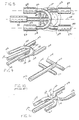
- Fig. 9 is an isometric view of an air fork in accordance with the present invention.
- Fig. 10 is an isometric view showing another air fork known in the prior art.
- Fig. 11 is an isometric view showing an alternate embodiment of an air fork in accordance with the present invention.
- US-A-3,072,096 describes a milking claw in the form of a one-piece elongated body provided with a lengthwise main milk channel.
- the inner ends of milk tubes nipples communicate with this channel, the nipples being disposed at 45-60° angles with respect to the channel.
- Also provided in the body is a lengthwise passage for air, along with nipples adapted to be connected with air tubes and communicating with the air passage.
- the air tube nipples are also inclined at an angle with respect to the lengthwise direction of the body, and are all directed in the same direction.
- Figs. 1-3 show a milking cluster 20 known in the prior art, and for which further reference may be had to U.S. Patents 4,530,307, 4,537,152, 5,178,095, and 5,218,924,.
- Dairy animal 22, such as a cow has an udder 24 and a plurality of teats 26, 28, 30, 32.
- the animal has a backbone 34 defining an axially extending longitudinal direction.
- a milking claw 36 has a plurality of inlets 38, 40, 42, 44, and an outlet 46.
- the claw lies along a central longitudinal axis 48 extending between the animal's front legs 31 and 33 and between the animal's rear legs 35 and 37 and generally parallel to backbone 34.
- Teat cups 50, 52, 54, 56 are each connected to a respective teat 26, 28, 30, 32 of udder 24.
- Short milk tubes 58, 60, 62, 64 each connect a respective claw inlet to a respective teat cup.
- An air fork 66, Figs. 2-5, has outlets 68, 70, 72, 74, and one or more inlets 76, 78.
- Air tubes 80, 82, 84, 86 each connect a respective air fork outlet to a respective teat cup.
- a milk hose 88 is connected to claw outlet 46.
- One or more vacuum pulsation air lines 90, 92 are connected to respective air fork inlets 76, 78.
- the claw has an upper eye hook 94 with a first upper circular hole 96 for hanging the claw when not in use, and a lower oblong hole 98 loosely receiving air fork inlets 76, 78 extending therethrough.
- milk hose 88 and air lines 90, 92 extend forwardly and then laterally to the side, though the milk hose and the air lines may extend longitudinally rearwardly along axis 48 between the cow's rear legs 35 and 37, or longitudinally forwardly along axis 48 between the cow's front legs 31 and 33.
- the milking arrangement shown in Figs. 1-5 is of the above noted alternating pulsation type. While vacuum is applied through air line 92, atmospheric air pressure is applied through air line 90, and vice versa. During the portion of the cycle when vacuum is applied through air line 92, such vacuum is applied to air fork inlet 78 and through air fork outlets 68 and 70 to air tubes 80 and 82 to rear teat cups 50 and 52, such that rear teats 26 and 28 are in the milk phase, and milk flows from the rear teats through milk tubes 58 and 60 to claw inlets 38 and 40 for collection in claw 36 and discharge through outlet 46 and out through milk hose 88.
- the atmospheric air pressure in the space between the teat cup shells and their respective inflations causes a differential pressure across the inflation or liner due to the vacuum on the inside thereof, which in turn collapses the liner, blocking milk flow, and also squeezing and massaging the teat to force blood circulation, as above noted, and all as is known in the prior art. It is typical that air lines 90 and 92 will be alternated between their opposite vacuum and atmospheric air pressure states at a pulsation rate between 45 and 60 cycles per minute.
- the other type of pulsation system is the simultaneous or single shot type.
- the air fork such as 100, Fig. 10 has a singular inlet 102 communicating with each of four outlets 104, 106, 108, 110 connected respectively to air lines 80, 82, 84, 86, such that all four teat cups 50, 52, 54, 56 will be in either the milk phase or in the rest phase at the same time, as noted above, and all as is known in the prior art.
- inlet 102 is in communication with all four outlets 104, 106, 108, 110.
- inlet 76 is in communication with outlets 72 and 74, but not outlets 68 and 70; and inlet 78 is in communication with outlets 68 and 70, but not outlets 72 and 74.
- the teat cups remain attached to the cow's teats until the milking operation is completed. If the teat cup becomes detached from the teat during milking, there will be a rapid admission of air into the interior of the inflation through the now open mouth thereof which formerly received the teat. This rapid admission of air is undesirable.
- One cause of such detachment can occur when the cow lifts either of her rear legs and steps forward, because either of the dew claws 112 or 114, Fig. 3, on the inside of her legs can hook an air tube and pull the teat cup off the teat.
- Right rear dew claw 112 can hook right air tube 80 and/or 84, and pull teat cup 50 and/or 54 off the respective teat.
- Left rear dew claw 114 can hook left air tube 82 and/or 86, and pull teat cup 52 and/or 56 off the respective teat.
- Each air tube 80, 82, 84, 86 extends from its respective air fork outlet laterally outwardly of its respective milk tube 58, 60, 62, 64 into the path of movement of dew claw 112 or 114.
- Figs. 6-9 and 11 illustrate the present invention solving the noted problem, and use like reference numerals from the above figures where appropriate to facilitate understanding.
- Bends are provided in the air fork outlets to route the air tubes initially longitudinally, rather than laterally.
- each air tube 80, 82, 84, 86 remains laterally inward of its respective milk tube 58, 60, 62, 64, to provide a narrower profile, as seen by contrasting Fig. 7 against Fig. 3.
- the air fork outlets direct the air tubes laterally inwardly of the milk tubes, rather than outwardly of the milk tubes.
- the dew claw 112 or 114 on the inside of her leg will not hook an air tube 80, 82, 84, 86 and pull the respective teat cup off the teat.
- Air fork 120 has air fork outlets 122, 124, 126, 128 extending generally axially longitudinally, i.e. generally parallel to the cow's backbone 34, such that air tubes 80, 82, 84, 86 initially extend generally axially longitudinally therefrom.
- Air tubes 80, 82, 84, 86 are laterally between respective milk tubes 58, 60, 62, 64 and central longitudinal axis 48.
- Air fork outlets 122 and 124 extend axially longitudinally rearwardly from the air fork and are laterally spaced on opposite sides of central longitudinal axis 48.
- Air fork outlets 126 and 128 extend axially longitudinally forwardly from the air fork and are laterally spaced on opposite sides of central longitudinal axis 48.
- Air fork outlets 122 and 126 are colinear and point in opposite longitudinal directions along a right longitudinal axis 130 laterally spaced from central longitudinal axis 48.
- Air fork outlets 124 and 128 are colinear and point in opposite longitudinal directions along a left longitudinal axis 132 laterally spaced from central longitudinal axis 48 on the opposite side thereof from right longitudinal axis 130.
- Axes 48, 130 and 132 are substantially parallel.
- Air fork 120 includes a first U-shaped portion 134 having first and second legs providing outlets 122 and 124, which legs are joined by a central bight 136.
- the air fork includes a second U-shaped portion 138 having legs providing outlets 126 and 128, which legs are joined by a central bight 140.
- U-shaped portions 134 and 138 extend in opposite longitudinal directions, with legs 122 and 124 pointing rearwardly, and legs 126 and 128 pointing forwardly. Bights 136 and 140 extend laterally and are proximate each other.
- U-shaped portions 134 and 138 are overlapped, with bight 136 being forward of bight 140.
- the U-shaped portions are preferably stainless steel, and may be welded to each other.
- Bight 140 has a port 142 facing longitudinally forwardly.
- Air fork inlet 144 extends axially longitudinally forwardly from port 142 for connection to air line 90.
- Inlet 144 is laterally spaced between legs 126 and 128.
- Bight 136 has a port 146 facing longitudinally forwardly.
- Air fork inlet 148 extends axially longitudinally forwardly from port 146 for connection to air line 92.
- Inlet 148 is laterally spaced between legs 126 and 128.
- Air fork 120 is for use with the above noted alternating type pulsation system.
- Inlet 144 is in communication with outlets 126 and 128, but not outlets 122 and 124.
- Inlet 148 is in communication with outlets 122 and 124, but not outlets 126 and 128.
- FIG. 11 illustrates an alternate embodiment showing an air fork 150 for use in a simultaneous, or single shot, type pulsation system.
- Air fork inlet 152 is in communication with each of the four air fork outlets 154, 156, 158, 160.
- the air fork has a U-shaped portion 162 with a central bight 164 and legs 154 and 156 extending axially longitudinally rearwardly therefrom.
- the air fork has a second U-shaped portion 166 with a central bight 168 and legs 158 and 160 extending axially longitudinally forwardly therefrom. Bights 164 and 168 have a common passage 170 therebetween.
- the air fork has a singular air inlet 152 extending longitudinally forwardly and communicating with bights 164 and 166 and common passage 170, and laterally spaced between legs 158 and 160.
Description
- The invention relates to dairy equipment, and more particularly to milking clusters according to
claim 1 and air forks for such milking clusters according to claim 11. - A milking cluster is an assembly attached to the dairy animal's udder during milking. The cluster includes a claw, four shell assemblies, four short milk tubes, four air tubes, and an air fork. Each shell assembly includes an outer shell and an inner liner called an inflation. The short milk tube connects the inflation to the claw which in turn is connected to a milk transport hose subject to vacuum or negative pressure. The air tube connects the space between the inflation and the shell to the air fork. The air fork is connected through one or more air lines to a pulsation device cycling vacuum off and on.
- When milking a dairy animal, the inside bore of the inflation is at the system vacuum level, and the space between the inflation and the shell is either at vacuum or at atmospheric pressure depending on the cycle of the pulsation device. When there is atmospheric pressure on the outside of the inflation in the space between the inflation and the shell, the vacuum on the inside of the inflation causes the inflation to collapse. This is known as the rest phase, during which there is no milk flow, i.e. liner closed. When there is vacuum on the outside of the inflation in the space between the inflation and the shell, such vacuum balances the vacuum on the inside of the inflation, and the inflation can relax or expand. This is the milk phase, during which milk flows, i.e. liner open. Most milking clusters operate efficiently with pulsation rates between 45 and 60 cycles per minute. The pulsing movement massages the teat. In the rest phase, the collapse of the inflation squeezes the teat, forcing blood in the teat to circulate. Without this rest phase, blood would not circulate throughout the teat, and injury to the teat might result. The milk phase and the rest phase may have some overlap.
- The purpose of the air fork is to distribute the vacuum and atmospheric air pulses to the shells, to apply the cycling vacuum and atmospheric air pulses to the space between the inflation and the shell. Pulsation systems are either simultaneous (sometimes call single shot) or alternating. Simultaneous means that all four teat cups will be in either the milk phase or the rest phase at the same time. Alternating pulsation systems will have the two front teat cups in the milk phase and the two rear teat cups in the rest phase at one time, and then alternate to just the opposite. Alternating pulsators are usually more desirable because they provide more even milk flow, excellent vacuum stability, and the option of adjusting the two rear teat cups to a greater milk/rest ratio than the two front teat cups.
- It is desirable that the teat cup remain attached to the teat until milking is completed, otherwise there is a rapid admission of air into the new open upper mouth of the liner, which is undesirable. One cause of such detachment is movement of the dairy animal if she lifts one of her rear legs and steps forward because the dew claw on the inside of her leg just above the hoof can hook the air tube between the air fork and the respective teat cup, and pull the teat cup off the teat. The present invention addresses and solves this problem according to the characterizing part of
claims 1 and 11. Preferrable aspects of the present invention are set out in the dependend claims. - Fig. 1 is a side view of a milking cluster attached to a dairy animal, as known in the prior art.
- Fig. 2 is an enlarged view of the milking cluster of Fig. 1.
- Fig. 3 is a view taken along line 3-3 of Fig. 2.
- Fig. 4 is a view taken along line 4-4 of Fig. 2. Fig. 5 is an isometric view of an air fork known in the prior art.
- Fig. 6 is a side view like Fig. 2 but illustrating the present invention.
- Fig. 7 is a view taken along line 7-7 of Fig. 6.
- Fig. 8 is a view taken along line 8-8 of Fig. 6.
- Fig. 9 is an isometric view of an air fork in accordance with the present invention.
- Fig. 10 is an isometric view showing another air fork known in the prior art.
- Fig. 11 is an isometric view showing an alternate embodiment of an air fork in accordance with the present invention.
- US-A-3,072,096 describes a milking claw in the form of a one-piece elongated body provided with a lengthwise main milk channel. The inner ends of milk tubes nipples communicate with this channel, the nipples being disposed at 45-60° angles with respect to the channel. Also provided in the body is a lengthwise passage for air, along with nipples adapted to be connected with air tubes and communicating with the air passage. The air tube nipples are also inclined at an angle with respect to the lengthwise direction of the body, and are all directed in the same direction.
- Figs. 1-3 show a
milking cluster 20 known in the prior art, and for which further reference may be had to U.S. Patents 4,530,307, 4,537,152, 5,178,095, and 5,218,924,.Dairy animal 22, such as a cow, has anudder 24 and a plurality ofteats backbone 34 defining an axially extending longitudinal direction. Amilking claw 36 has a plurality ofinlets outlet 46. The claw lies along a centrallongitudinal axis 48 extending between the animal'sfront legs 31 and 33 and between the animal'srear legs backbone 34.Teat cups respective teat udder 24.Short milk tubes air fork 66, Figs. 2-5, hasoutlets more inlets 76, 78.Air tubes milk hose 88 is connected toclaw outlet 46. One or more vacuumpulsation air lines air fork inlets 76, 78. The claw has anupper eye hook 94 with a first uppercircular hole 96 for hanging the claw when not in use, and a loweroblong hole 98 loosely receivingair fork inlets 76, 78 extending therethrough. In herringbone type and other conventional milking parlors, it is typical thatmilk hose 88 andair lines axis 48 between the cow'srear legs axis 48 between the cow'sfront legs 31 and 33. - The milking arrangement shown in Figs. 1-5 is of the above noted alternating pulsation type. While vacuum is applied through
air line 92, atmospheric air pressure is applied throughair line 90, and vice versa. During the portion of the cycle when vacuum is applied throughair line 92, such vacuum is applied to air fork inlet 78 and throughair fork outlets air tubes rear teat cups rear teats milk tubes claw inlets 38 and 40 for collection inclaw 36 and discharge throughoutlet 46 and out throughmilk hose 88. Milk flows from the rear teats because vacuum is applied to the space between the rear teat cup shells and their respective inflations such that the latter can relax and expand, as above noted, and all as is known in the prior art. During this portion of the cycle, atmospheric air pressure is applied byair line 90 toair fork inlet 76 toair fork outlets air tubes front teat cups air lines - The other type of pulsation system is the simultaneous or single shot type. In this type of system, the air fork, such as 100, Fig. 10, has a singular inlet 102 communicating with each of four
outlets air lines teat cups air fork 100 of Fig. 10, inlet 102 is in communication with all fouroutlets air fork 66 of Fig. 5,inlet 76 is in communication withoutlets outlets outlets outlets - As noted above, it is desirable that the teat cups remain attached to the cow's teats until the milking operation is completed. If the teat cup becomes detached from the teat during milking, there will be a rapid admission of air into the interior of the inflation through the now open mouth thereof which formerly received the teat. This rapid admission of air is undesirable. One cause of such detachment can occur when the cow lifts either of her rear legs and steps forward, because either of the
dew claws rear dew claw 112 can hookright air tube 80 and/or 84, and pullteat cup 50 and/or 54 off the respective teat. Leftrear dew claw 114 can hookleft air tube 82 and/or 86, and pullteat cup 52 and/or 56 off the respective teat. Eachair tube respective milk tube dew claw - Figs. 6-9 and 11 illustrate the present invention solving the noted problem, and use like reference numerals from the above figures where appropriate to facilitate understanding. Bends are provided in the air fork outlets to route the air tubes initially longitudinally, rather than laterally. In this manner, each
air tube respective milk tube rear legs dew claw air tube -
Air fork 120, Figs. 6-9, hasair fork outlets backbone 34, such thatair tubes Air tubes respective milk tubes longitudinal axis 48.Air fork outlets longitudinal axis 48.Air fork outlets longitudinal axis 48.Air fork outlets longitudinal axis 130 laterally spaced from centrallongitudinal axis 48.Air fork outlets longitudinal axis 132 laterally spaced from centrallongitudinal axis 48 on the opposite side thereof from rightlongitudinal axis 130.Axes -
Air fork 120 includes a firstU-shaped portion 134 having first and secondlegs providing outlets central bight 136. The air fork includes a secondU-shaped portion 138 havinglegs providing outlets central bight 140.U-shaped portions legs legs Bights - In the embodiment in Fig. 9,
U-shaped portions bight 136 being forward ofbight 140. The U-shaped portions are preferably stainless steel, and may be welded to each other.Bight 140 has aport 142 facing longitudinally forwardly.Air fork inlet 144 extends axially longitudinally forwardly fromport 142 for connection toair line 90.Inlet 144 is laterally spaced betweenlegs Bight 136 has aport 146 facing longitudinally forwardly.Air fork inlet 148 extends axially longitudinally forwardly fromport 146 for connection toair line 92.Inlet 148 is laterally spaced betweenlegs -
Air fork 120, Fig. 9, is for use with the above noted alternating type pulsation system.Inlet 144 is in communication withoutlets outlets Inlet 148 is in communication withoutlets outlets - Fig. 11 illustrates an alternate embodiment showing an
air fork 150 for use in a simultaneous, or single shot, type pulsation system.Air fork inlet 152 is in communication with each of the fourair fork outlets U-shaped portion 162 with acentral bight 164 andlegs U-shaped portion 166 with acentral bight 168 andlegs 158 and 160 extending axially longitudinally forwardly therefrom.Bights common passage 170 therebetween. The air fork has asingular air inlet 152 extending longitudinally forwardly and communicating withbights common passage 170, and laterally spaced betweenlegs 158 and 160. - It is recognized that various equivalents, alternatives and modifications are possible within the scope of the appended claims.
Claims (15)
- A milking cluster for a dairy animal having an udder and a plurality of teats, and a backbone defining an axially extending longitudinal direction, comprising:characterised in that said first and third air fork outlets (122, 126; 154, 158) point in opposite longitudinal directions substantially parallel to said central longitudinal axis (48), and said second and fourth air fork outlets (124, 128; 156, 160) point in opposite longitudinal directions substantially parallel to said central longitudinal axis (48),a claw (36) having a plurality of inlets (38, 40, 42, 44), and an outlet (46), said claw when in use lying along a central longitudinal axis (48) extending between the animal's legs and generally parallel to said backbone;a plurality of teat cups (50, 52, 54, 56), each connectable to a respective teat when in use;a plurality of milk tubes (58, 60, 62, 64), each connecting a respective claw inlet to a respective teat cup;an air fork (120; 150) having a plurality of outlets (122, 124, 126, 128; 154, 156, 158, 160), and one or more inlets (144, 148; 152);a plurality of air tubes (80, 82, 84, 86), each connecting a respective air fork outlet to a respective teat cup;a milk hose (88) connected to said claw outlet;one or more vacuum pulsation air lines (90, 92) connected to said one or more air fork inlets;wherein said air fork outlets comprise first and second air fork outlets (122, 124; 154, 156) located rearwardly in said air fork and laterally spaced on opposite sides of said central longitudinal axis (48), and third and fourth air fork outlets (126, 128; 158, 160) located forwardly in said air fork and laterally spaced on opposite sides of said central longitudinal axis (48),
whereby said first (122; 154), second (124; 156), third (126; 158) and fourth (128; 160) air fork outlets direct said air tubes laterally inwardly of said milk tubes. - A milking cluster according to claim 1 wherein each said air tube extends from its respective said air fork outlet and is laterally between its respective said milk tube and said central longitudinal axis (48).
- A milking cluster according to claim 1 or 2, wherein said first and third air fork outlets (122, 126; 154, 158) are colinear and arranged along a right longitudinal axis (130) laterally spaced from said central longitudinal axis (48), and said second and fourth air fork outlets (124, 128; 156, 160) are colinear and arranged along a left longitudinal axis (132) laterally spaced from said central longitudinal axis (48) on the opposite side thereof from said right longitudinal axis (130).
- A milking cluster according to any preceding claim wherein said air fork (120; 150) comprises :a first U-shaped portion (134; 162) having first (122; 154) and second (124; 156) legs joined by a first central bight (136; 164), and first leg providing said first air fork outlet, said second leg providing said second air fork outlet;a second U-shaped portion (138; 166) having third (126; 158) and fourth (128; 160) legs joined by a second central bight (140; 168), said third leg providing said third air fork outlet, said fourth leg providing said fourth air fork outlet.
- A milking cluster according to claim 4 wherein said first and second U-shaped portions (136, 138; 162, 166) extend in opposite longitudinal directions, with said first and second legs (122, 124; 154, 156) pointing rearwardly, and said third and fourth legs (126, 128; 158, 160) pointing forwardly.
- A milking cluster according to claim 5 wherein said first and second bights (136, 140; 164, 168) extend laterally and are proximate each other.
- A milking cluster according to claim 6 wherein said first and second U-shaped portions (134, 138) are overlapped, and wherein said first bight is forward of said second bight.
- A milking cluster according to claim 7 wherein:said first and second legs (122, 124) extend longitudinally rearwardly from said first bight (136);said first bight (136) has a first port (146) facing in a first longitudinal direction;said one or more air fork inlets (144, 148) comprise a first air fork inlet (148) extending longitudinally in said first longitudinal direction from said first port (146);said third and fourth legs (126, 128) extend longitudinally forwardly from said second bight (140);said second bight (140) has a second port (142) facing in said first longitudinal direction;said one or more air fork inlets (144, 148) comprise a second air fork inlet (144) extending longitudinally in said first longitudinal direction from said second port (142).
- A milking cluster according to claim 6 wherein:said first and second legs (154,156) extend longitudinally rearwardly from said first bight (164);said third and fourth legs (158,160) extend longitudinally forwardly from said second bight (168) ;said first and second bights are joined by a common passage (170) therebetween;said one or more air fork inlets comprise a singular air fork inlet (152) extending longitudinally and communicating with said common passage.
- A milking cluster according to claim 9 wherein one of said bights has a port facing in a first longitudinal direction, and said air fork inlet (152) extends longitudinally from said port.
- An air fork for a milking cluster for a dairy animal having an udder and a plurality of teats, and a backbone defining an axially extending longitudinal direction, said cluster having a claw (36) with a plurality of inlets (38, 40, 42, 44), an outlet (46), a plurality of teat cups (50, 52, 54, 56), each connected to a respective teat when in use, a plurality of milk tubes, each connecting a respective claw inlet to a respective teat cup, a plurality of air tubes (80, 82, 84, 86), each connected to a respective teat cup, a milk hose (88) connected to said claw outlet, and one or more vacuum pulsation air lines (90, 92),characterised in that said first (122; 154) and third (126; 158) air fork outlets point in opposite longitudinal directions substantially parallel to said central longitudinal axis (48), and said second (124, 156) and fourth (128; 160) air fork outlets point in opposite longitudinal directions substantially parallel to said central longitudinal axis (48).said air fork when in use lying along a central longitudinal axis (48) extending between the animal's legs and generally parallel to said backbone and said air fork comprising a plurality of outlets (122, 124, 126, 128; 154, 156, 158, 160) for connection to said air tubes, and one or more inlets (144, 148; 152)wherein said air fork outlets comprise first and second air fork outlets (122, 124; 154, 156) located rearwardly in said air fork and laterally spaced on opposite sides of said central longitudinal axis (48), and third and fourth air fork outlets (126, 128; 158, 160) located forwardly in said air fork and laterally spaced on opposite sides of said central longitudinal axis (48),
- An air fork according to claim 11, wherein said first (122, 154) and third (126; 158) air fork outlets are colinear and arranged along a right longitudinal axis (130) laterally spaced from said central longitudinal axis (48), and said second (124; 156) and fourth (128; 160) air fork outlets are colinear and arranged along a left longitudinal axis (132) laterally spaced from said central longitudinal axis on the opposite side thereof from said right longitudinal axis (48).
- An air fork according to claim 11 or 12 wherein said air fork (120; 150) comprises:a first U-shaped portion (134, 162) having first (122; 154) and second (124; 156) legs joined by a first central bight (136, 164), said first leg providing said first air fork outlet, said second leg providing said second air fork outlet ;a second U-shaped portion (138, 166) having third (126; 158) and fourth (128; 160) legs joined by a second central bight (140; 168) said third leg providing said third air fork outlet, said fourth leg providing said fourth air fork outlet.
- An air fork according to claim 13 wherein:said first and second U-shaped portions (136, 138) extend in opposite longitudinal directions, with said first and second legs pointing (122, 124) rearwardly, and said third and fourth legs pointing (126, 128) forwardly;said first and second bights (136, 140) extend laterally and are proximate each other;said first and second U-shaped portions (136, 138) are overlapped, with said first bight (136) being forward of said second bight (140);said first and second legs (122, 124) extend longitudinally rearwardly from said first bight (136);said first bight (136) has a first port (146) facing in a first longitudinal direction;said one or more air fork inlets (144, 148) comprise a first air fork inlet (148) extending longitudinally in said first longitudinal direction from said first port (146);said third and fourth legs (126, 128) extend longitudinally forwardly from said second bight (140);said second bight (140) has a second port (142) facing in said first longitudinal direction;said one or more air fork inlets (144, 148) comprise a second air fork inlet (144) extending longitudinally in said first longitudinal direction from said second port (142).
- An air fork according to claim 13 wherein:said first and second U-shaped portions (162, 166) extend in opposite longitudinal directions, with said first and second legs (154, 156) pointing rearwardly, and said third and fourth legs (158, 160) pointing forwardly;said first and second bights (164, 168) extend laterally and are proximate each other;said first and second legs (154, 156) extend longitudinally rearwardly from said first bight (164);said third and fourth legs (158, 160) extend longitudinally rearwardly from said second bight (168);said first and second bights (164, 168) are joined by a common passage (170) therebetween;said one or more air fork inlets comprise a singular air fork inlet (152) extending longitudinally and communicating with said common passage.
Applications Claiming Priority (2)
| Application Number | Priority Date | Filing Date | Title |
|---|---|---|---|
| US08/411,417 US5586518A (en) | 1995-03-27 | 1995-03-27 | Milking cluster air fork |
| US411417 | 1995-03-27 |
Publications (2)
| Publication Number | Publication Date |
|---|---|
| EP0734648A1 EP0734648A1 (en) | 1996-10-02 |
| EP0734648B1 true EP0734648B1 (en) | 2001-05-30 |
Family
ID=23628834
Family Applications (1)
| Application Number | Title | Priority Date | Filing Date |
|---|---|---|---|
| EP96302130A Expired - Lifetime EP0734648B1 (en) | 1995-03-27 | 1996-03-27 | Milking cluster air fork |
Country Status (4)
| Country | Link |
|---|---|
| US (1) | US5586518A (en) |
| EP (1) | EP0734648B1 (en) |
| DE (1) | DE69613037T2 (en) |
| ES (1) | ES2158245T3 (en) |
Families Citing this family (20)
| Publication number | Priority date | Publication date | Assignee | Title |
|---|---|---|---|---|
| US6257847B1 (en) | 1995-08-03 | 2001-07-10 | Medela, Inc. | Diaphragm pump and pump for double-breast pumping |
| US6481986B1 (en) | 1995-08-03 | 2002-11-19 | Medela Holding Ag | Vacuum adjustment mechanism particularly adapted for a breastpump |
| SE511150C2 (en) * | 1996-02-05 | 1999-08-09 | Alfa Laval Agri Ab | claw |
| DE59610174D1 (en) * | 1996-04-14 | 2003-04-03 | Medela Ag Baar | Breast milk suction device |
| US6139521A (en) * | 1996-06-03 | 2000-10-31 | Medela Holding Ag | Breastpump having particular application as a small motorized pump capable of double-breast pumping |
| US5960738A (en) * | 1998-12-07 | 1999-10-05 | Dec International, Inc. | Milking cluster hose positioner |
| US6673036B1 (en) | 1999-10-13 | 2004-01-06 | The First Years Inc. | Pumping breast milk |
| IT250138Y1 (en) * | 2000-11-28 | 2003-07-24 | Interpuls Spa | MILKING GROUP WITH SHORT MILK PIPES EQUIPPED WITH INTERNAL WEEKLY |
| US6749582B2 (en) * | 2002-04-30 | 2004-06-15 | The First Years Inc. | Pumping breast milk |
| SE0201596D0 (en) * | 2002-05-29 | 2002-05-29 | Delaval Holding Ab | A device for cleaning the teats of an animal |
| US7021239B2 (en) * | 2004-04-20 | 2006-04-04 | Bou-Matic Technologies Corp. | Milking claw top |
| US6981468B1 (en) | 2004-04-20 | 2006-01-03 | Bou-Matic Technologies Corp. | Milking claw bottom |
| US7396339B2 (en) * | 2004-04-30 | 2008-07-08 | The First Years Inc. | Pumping breast milk |
| US8945046B2 (en) | 2008-04-03 | 2015-02-03 | Lyndon Brittner | Hands-free breast pump system |
| US8398584B2 (en) | 2009-01-16 | 2013-03-19 | Learning Curve Brands, Inc. | Breast pump and method of use |
| DE102011001404A1 (en) | 2011-03-18 | 2012-09-20 | Gea Farm Technologies Gmbh | Milking parlor and milking parlor with such a milking parlor |
| EP3335548B1 (en) | 2011-03-18 | 2021-03-10 | GEA Farm Technologies GmbH | Teat cup and a milking stall including such a teat cup |
| DE102012110503A1 (en) | 2012-03-14 | 2013-09-19 | Gea Farm Technologies Gmbh | Divider of a milking parlor arrangement and milking parlor arrangement |
| DE102012102133A1 (en) | 2012-03-14 | 2013-09-19 | Gea Farm Technologies Gmbh | MELSTAND ASSEMBLY WITH AN INNER ROBOT DEVICE |
| DE102014107124A1 (en) | 2014-05-20 | 2015-11-26 | Gea Farm Technologies Gmbh | Arm arrangement for a milking parlor arrangement for the automatic milking of dairy animals, divider of a milking parlor arrangement and milking parlor arrangement |
Family Cites Families (10)
| Publication number | Priority date | Publication date | Assignee | Title |
|---|---|---|---|---|
| US3079891A (en) * | 1960-07-25 | 1963-03-05 | Bernard F Miller | Milking cup assembly |
| US3072096A (en) * | 1960-08-11 | 1963-01-08 | Norbert M Kluge | Claw for milking machines |
| US3776196A (en) * | 1972-04-19 | 1973-12-04 | J Luiz | Claw assembly for milking machines |
| US4530307A (en) * | 1982-10-06 | 1985-07-23 | Dec International, Inc. | Teat cup inflation |
| US4537152A (en) * | 1984-06-01 | 1985-08-27 | Dec International, Inc. | Milking claw |
| EP0346952A3 (en) * | 1985-07-19 | 1990-02-14 | C. van der Lely N.V. | An implement for milking animals, such as cows |
| US4941433A (en) * | 1988-05-23 | 1990-07-17 | Agri-Automation Company, Ltd. | Milking method and related apparatus |
| SU1667753A1 (en) * | 1989-04-14 | 1991-08-07 | Украинский научно-исследовательский институт механизации и электрификации сельского хозяйства | For milking apparatus |
| US5178095A (en) * | 1991-06-13 | 1993-01-12 | Dec International, Inc. | Milking system with positive pressure on thin liner |
| US5218924A (en) * | 1992-03-19 | 1993-06-15 | Dec International, Inc. | Milking system with variable pressure source |
-
1995
- 1995-03-27 US US08/411,417 patent/US5586518A/en not_active Expired - Lifetime
-
1996
- 1996-03-27 DE DE69613037T patent/DE69613037T2/en not_active Expired - Fee Related
- 1996-03-27 EP EP96302130A patent/EP0734648B1/en not_active Expired - Lifetime
- 1996-03-27 ES ES96302130T patent/ES2158245T3/en not_active Expired - Lifetime
Also Published As
| Publication number | Publication date |
|---|---|
| ES2158245T3 (en) | 2001-09-01 |
| DE69613037T2 (en) | 2001-09-13 |
| US5586518A (en) | 1996-12-24 |
| DE69613037D1 (en) | 2001-07-05 |
| EP0734648A1 (en) | 1996-10-02 |
Similar Documents
| Publication | Publication Date | Title |
|---|---|---|
| EP0734648B1 (en) | Milking cluster air fork | |
| EP1109438B1 (en) | Method and apparatus for cleaning the teats of a dairy animal's udder | |
| CA2498999C (en) | Milking claw top | |
| US9439391B2 (en) | Dairy milking devices and methods | |
| EP1104986B1 (en) | An apparatus for milking an animal | |
| US20040060520A1 (en) | Short milk tube | |
| US4807566A (en) | Milk claw | |
| EP1588607B1 (en) | Milking claw | |
| US5752462A (en) | Teat cup inflation | |
| EP0031246B1 (en) | Improvements in or relating to methods of milking animals, apparatus for use in milking machines and to milking machines | |
| JP2002523202A (en) | An easily bendable tube for two separate fluids | |
| US3776196A (en) | Claw assembly for milking machines | |
| US4434744A (en) | Methods of and/or apparatus for milking animals | |
| HU192216B (en) | Milking apparatus provided with collecting unit | |
| US3072096A (en) | Claw for milking machines | |
| WO2004084622A1 (en) | A set of teatcups, and a milking member | |
| US2045454A (en) | Combination pneumatic pulsator and milk claw | |
| RU2040161C1 (en) | Milking apparatus for cows | |
| EP0093216A1 (en) | Improvements in or relating to methods of and/or apparatus for milking animals | |
| NZ196137A (en) | Teat claw;common vortex chamber reduces milk backflow | |
| GB2052941A (en) | Milking claw |
Legal Events
| Date | Code | Title | Description |
|---|---|---|---|
| PUAI | Public reference made under article 153(3) epc to a published international application that has entered the european phase |
Free format text: ORIGINAL CODE: 0009012 |
|
| AK | Designated contracting states |
Kind code of ref document: A1 Designated state(s): DE ES FR GB IT |
|
| 17P | Request for examination filed |
Effective date: 19970311 |
|
| 17Q | First examination report despatched |
Effective date: 19990621 |
|
| GRAG | Despatch of communication of intention to grant |
Free format text: ORIGINAL CODE: EPIDOS AGRA |
|
| GRAG | Despatch of communication of intention to grant |
Free format text: ORIGINAL CODE: EPIDOS AGRA |
|
| GRAG | Despatch of communication of intention to grant |
Free format text: ORIGINAL CODE: EPIDOS AGRA |
|
| GRAH | Despatch of communication of intention to grant a patent |
Free format text: ORIGINAL CODE: EPIDOS IGRA |
|
| GRAH | Despatch of communication of intention to grant a patent |
Free format text: ORIGINAL CODE: EPIDOS IGRA |
|
| GRAA | (expected) grant |
Free format text: ORIGINAL CODE: 0009210 |
|
| AK | Designated contracting states |
Kind code of ref document: B1 Designated state(s): DE ES FR GB IT |
|
| REF | Corresponds to: |
Ref document number: 69613037 Country of ref document: DE Date of ref document: 20010705 |
|
| ET | Fr: translation filed | ||
| ITF | It: translation for a ep patent filed |
Owner name: RACHELI & C. S.R.L. |
|
| REG | Reference to a national code |
Ref country code: ES Ref legal event code: FG2A Ref document number: 2158245 Country of ref document: ES Kind code of ref document: T3 |
|
| REG | Reference to a national code |
Ref country code: GB Ref legal event code: IF02 |
|
| PLBE | No opposition filed within time limit |
Free format text: ORIGINAL CODE: 0009261 |
|
| STAA | Information on the status of an ep patent application or granted ep patent |
Free format text: STATUS: NO OPPOSITION FILED WITHIN TIME LIMIT |
|
| 26N | No opposition filed | ||
| PGFP | Annual fee paid to national office [announced via postgrant information from national office to epo] |
Ref country code: GB Payment date: 20070216 Year of fee payment: 12 |
|
| PGFP | Annual fee paid to national office [announced via postgrant information from national office to epo] |
Ref country code: ES Payment date: 20070326 Year of fee payment: 12 |
|
| PGFP | Annual fee paid to national office [announced via postgrant information from national office to epo] |
Ref country code: DE Payment date: 20070330 Year of fee payment: 12 |
|
| PGFP | Annual fee paid to national office [announced via postgrant information from national office to epo] |
Ref country code: IT Payment date: 20070529 Year of fee payment: 12 |
|
| PGFP | Annual fee paid to national office [announced via postgrant information from national office to epo] |
Ref country code: FR Payment date: 20070301 Year of fee payment: 12 |
|
| GBPC | Gb: european patent ceased through non-payment of renewal fee |
Effective date: 20080327 |
|
| REG | Reference to a national code |
Ref country code: FR Ref legal event code: ST Effective date: 20081125 |
|
| PG25 | Lapsed in a contracting state [announced via postgrant information from national office to epo] |
Ref country code: DE Free format text: LAPSE BECAUSE OF NON-PAYMENT OF DUE FEES Effective date: 20081001 |
|
| PG25 | Lapsed in a contracting state [announced via postgrant information from national office to epo] |
Ref country code: FR Free format text: LAPSE BECAUSE OF NON-PAYMENT OF DUE FEES Effective date: 20080331 |
|
| REG | Reference to a national code |
Ref country code: ES Ref legal event code: FD2A Effective date: 20080328 |
|
| PG25 | Lapsed in a contracting state [announced via postgrant information from national office to epo] |
Ref country code: GB Free format text: LAPSE BECAUSE OF NON-PAYMENT OF DUE FEES Effective date: 20080327 |
|
| PG25 | Lapsed in a contracting state [announced via postgrant information from national office to epo] |
Ref country code: ES Free format text: LAPSE BECAUSE OF NON-PAYMENT OF DUE FEES Effective date: 20080328 |
|
| PG25 | Lapsed in a contracting state [announced via postgrant information from national office to epo] |
Ref country code: IT Free format text: LAPSE BECAUSE OF NON-PAYMENT OF DUE FEES Effective date: 20080327 |