EP1607760A1 - Circuit d'alimentation d'une bobine et sonde et spectomètre RMN comportant un tel circuit - Google Patents
Circuit d'alimentation d'une bobine et sonde et spectomètre RMN comportant un tel circuit Download PDFInfo
- Publication number
- EP1607760A1 EP1607760A1 EP05360019A EP05360019A EP1607760A1 EP 1607760 A1 EP1607760 A1 EP 1607760A1 EP 05360019 A EP05360019 A EP 05360019A EP 05360019 A EP05360019 A EP 05360019A EP 1607760 A1 EP1607760 A1 EP 1607760A1
- Authority
- EP
- European Patent Office
- Prior art keywords
- circuit
- additional
- conductors
- oscillating circuit
- supply circuit
- Prior art date
- Legal status (The legal status is an assumption and is not a legal conclusion. Google has not performed a legal analysis and makes no representation as to the accuracy of the status listed.)
- Granted
Links
- 239000004020 conductor Substances 0.000 claims abstract description 88
- 230000008878 coupling Effects 0.000 claims abstract description 60
- 238000010168 coupling process Methods 0.000 claims abstract description 60
- 238000005859 coupling reaction Methods 0.000 claims abstract description 60
- 239000000523 sample Substances 0.000 claims abstract description 18
- 230000005540 biological transmission Effects 0.000 claims description 26
- 239000003990 capacitor Substances 0.000 claims description 9
- 238000009413 insulation Methods 0.000 claims description 9
- 230000002452 interceptive effect Effects 0.000 claims description 6
- 230000000694 effects Effects 0.000 claims description 4
- 230000001939 inductive effect Effects 0.000 claims description 4
- 239000007790 solid phase Substances 0.000 claims description 2
- 238000004611 spectroscopical analysis Methods 0.000 claims description 2
- 230000003534 oscillatory effect Effects 0.000 claims 3
- 238000005481 NMR spectroscopy Methods 0.000 abstract description 12
- 238000006073 displacement reaction Methods 0.000 description 5
- 230000006978 adaptation Effects 0.000 description 2
- 230000005284 excitation Effects 0.000 description 2
- 230000033001 locomotion Effects 0.000 description 2
- 238000012565 NMR experiment Methods 0.000 description 1
- 238000004458 analytical method Methods 0.000 description 1
- 230000000295 complement effect Effects 0.000 description 1
- 238000001514 detection method Methods 0.000 description 1
- 238000002955 isolation Methods 0.000 description 1
- 239000002184 metal Substances 0.000 description 1
- 238000012986 modification Methods 0.000 description 1
- 230000004048 modification Effects 0.000 description 1
- 230000037361 pathway Effects 0.000 description 1
- 239000007787 solid Substances 0.000 description 1
Images







Classifications
-
- G—PHYSICS
- G01—MEASURING; TESTING
- G01R—MEASURING ELECTRIC VARIABLES; MEASURING MAGNETIC VARIABLES
- G01R33/00—Arrangements or instruments for measuring magnetic variables
- G01R33/20—Arrangements or instruments for measuring magnetic variables involving magnetic resonance
- G01R33/28—Details of apparatus provided for in groups G01R33/44 - G01R33/64
- G01R33/32—Excitation or detection systems, e.g. using radio frequency signals
- G01R33/36—Electrical details, e.g. matching or coupling of the coil to the receiver
- G01R33/3628—Tuning/matching of the transmit/receive coil
- G01R33/3635—Multi-frequency operation
-
- G—PHYSICS
- G01—MEASURING; TESTING
- G01R—MEASURING ELECTRIC VARIABLES; MEASURING MAGNETIC VARIABLES
- G01R33/00—Arrangements or instruments for measuring magnetic variables
- G01R33/20—Arrangements or instruments for measuring magnetic variables involving magnetic resonance
- G01R33/28—Details of apparatus provided for in groups G01R33/44 - G01R33/64
- G01R33/32—Excitation or detection systems, e.g. using radio frequency signals
- G01R33/36—Electrical details, e.g. matching or coupling of the coil to the receiver
- G01R33/3628—Tuning/matching of the transmit/receive coil
-
- G—PHYSICS
- G01—MEASURING; TESTING
- G01R—MEASURING ELECTRIC VARIABLES; MEASURING MAGNETIC VARIABLES
- G01R33/00—Arrangements or instruments for measuring magnetic variables
- G01R33/20—Arrangements or instruments for measuring magnetic variables involving magnetic resonance
- G01R33/28—Details of apparatus provided for in groups G01R33/44 - G01R33/64
- G01R33/32—Excitation or detection systems, e.g. using radio frequency signals
- G01R33/34—Constructional details, e.g. resonators, specially adapted to MR
- G01R33/34092—RF coils specially adapted for NMR spectrometers
Definitions
- the present invention relates to the field of power supplies Precision electric, especially in the field of Resonance Magnographic Nucléaire, and relates to a power supply circuit of a coil, in particular a sample coil, as well as an NMR probe and an NMR spectrometer comprising such a circuit.
- the present invention aims to propose a solution simple to overcome at least some of the disadvantages supra.
- the subject of the invention is a feed circuit a coil, in particular an NMR coil or sample coil, comprising two portions of connected feed or transmission line each at one of the two ends of this coil, said portions of line forming with said coil an oscillating circuit or first circuit oscillator having a determined resonant frequency, characterized in that the two portions of line each comprise at least two conductors, one of which is connected to the coil, and identical structures and lengths of identical connected conductors, this common length being substantially a multiple of half the resonance wavelength of said oscillating circuit, in that the conductors connected to the coil at one of their ends are connected between them at their other end by a symmetrical tuning circuit or component adjustable complement this oscillating circuit, and in that said oscillating circuit to symmetrical structure is powered by a primary power circuit by via a magnetic coupling, capacitive energy transfer or magneto-capacitive of said primary power circuit with one at less than two conductors connected to the coil and to the circuit or component Okay.
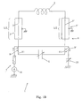
- FIGS. 1A, 1B, 2, 3A, 3B, 4, 5A, 5B and 5C show each a circuit 1 for feeding a coil 2, in particular a coil NMR or sample coil, comprising two portions of line supply or transmission 3 and 3 'each connected to one of the two ends of this coil 2, said line portions 3, 3 'forming with said coil 2 an oscillating circuit or first oscillating circuit 4 having a determined resonance frequency.
- this supply circuit 1 is characterized in that the two line portions 3 and 3 'each comprise at least two conductors 5, 5 '; 5 ", 5" ', one of which 5, 5' is connected to the spool 2, and have between them identical structures and lengths of identical connected conductors, this common length being substantially a multiple of half the resonance wavelength of said circuit oscillating 4, in that the conductors 5, 5 'connected to the coil 2 to one of their ends are connected to each other at their other end by a circuit or adjustable symmetrical tuning component 6 completing this oscillating circuit 4, and in that said oscillating circuit 4 with symmetrical structure is powered by a primary power supply circuit 7 via a transfer of energy by magnetic coupling, capacitive or magneto-capacitive said primary supply circuit 7 with at least one of the two conductors 5, 5 'connected to the coil 2 and to the circuit or tuning component 6.
- the feed circuit primary 7 may be partially confused with the first oscillating circuit 4, integrating a common circuit part 7 'with this first circuit oscillating, and include, on the one hand, a radio frequency generator 8 adjusted to the determined resonant frequency of the first oscillating circuit 4 and connected to said first oscillating circuit 4 at a terminal of the circuit or adjustable symmetrical tuning component 6 via a capacitance 8 'and on the other hand a circuit or matching component 10 connected at the other terminal of the circuit or tunable symmetric tuning component 6, the matching component 10 and symmetric tuning component adjustable 6 part of both circuits 4 and 7 consisting of capacities and the generator 8 operating continuously, intermittently or pulsed way.
- a radio frequency generator 8 adjusted to the determined resonant frequency of the first oscillating circuit 4 and connected to said first oscillating circuit 4 at a terminal of the circuit or adjustable symmetrical tuning component 6 via a capacitance 8 'and on the other hand a circuit or matching component 10 connected at the other terminal of the circuit or tunable symmetric tuning component 6,
- the feed circuit primary 7 consists of a separate circuit and includes, in addition to a radio frequency generator 8 adjusted to the determined resonant frequency and the element or elements 9, 9 'participating in the coupling with at least one of the two conductors 5, 5 'of one or more line portions 3, 3' connected to the coil 2 and the circuit or tuning component 6, also a circuit or component 10, designed to optimize the coupling and to limit certain effects at the primary power supply circuit 7, the generator 8 operating continuously, intermittently or pulsed.
- the coupling consists preferentially in a coupling essentially of magnetic nature and in that the matching circuit or component 10 is preferably a adjustable capacity to cancel the inductive reactance at the level of primary supply circuit 7.
- the energy transfer by coupling between the primary supply circuit 7 and the oscillating circuit 4 consists of a double coupling and affects symmetrically and equivalent the conductors 5 and 5 '; 5 ", 5" 'connected to the spool 2 of the two transmission line portions 3 and 3 '(see FIGS. 1B, 3A, 3B, 4, 5A, 5B and 5C).
- the or each of the two coupling (s) carrying out the energy transfer consists of a mainly magnetic coupling between, on the one hand, a segment 11 of a conductor 5, 5 'connected to the coil 2 of one of the line portions 3, 3' of the oscillating circuit 4 and, on the other hand, a segment 9, 9 'of the line connecting the generator 8 to the matching component 10 in the supply circuit 7, these two segments 11 and 9, 9 'of determined lengths being parallel and in close proximity to one another and forming lines of Lick.
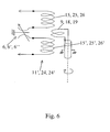
- the coupling the energy transfer consists of a magneto-capacitive, symmetrical coupling or asymmetric, between, on the one hand, a solenoid 9 connected in series in the primary power supply circuit 7 and, on the other hand, an assembly 11 ' capacitance / inductance (s) connected in series in the oscillating circuit 4, said capacity that can correspond to the tuning component 6 and the inductances to comprise two equivalent inductances 15, 15 'connected in series on and other of said capacity 6, possibly forming part each of a LC circuit.
- the supply circuit comprises at least one oscillating circuit 12, 12 'having a resonance frequency different from that of the first oscillating circuit 4 and formed, where appropriate each, by the coil 2, mutually equivalent portions of a conductor 5, 5 ', 5 “, 5 “'of the two line portions 3, 3' of the first oscillating circuit 4 and, optionally, two portions of additional transmission line 13, 13 '; 14, 14 'each connected by one end of their at least one conductor 13 ", 14" respectively to one of the leads 5, 5 "; 5 ', 5"' of one of the two portions of line 3, 3 'mentioned above and having between them identical structures and lengths.
- At least one or each additional oscillating circuit 12, 12 ' is powered by a corresponding primary power supply circuit 16, 16 ', via a magnetic coupling, capacitive energy transfer or magneto-capacitive of this primary supply circuit 16, 16 'respectively corresponding with at least one of the 13 "; 14" conductors connected to or forming part of the line portions 3, 3 'of the first oscillating circuit 4, from at least one of the two additional transmission line portions 13, 13 '; 14, 14 '( Figures 2, 3A, 3B, 4, 5A, 5B and 5C).
- spectrometric analyzes require the provision of three different excitation frequencies for the detection of three types of nuclei.
- These three frequency channels include usually a high frequency corresponding to the resonance of the nucleus H (proton - called H channel) and two other channels encompassing nuclei resonant in a lower frequency band.
- This band of lower frequencies is divided into two sub-bands, the Y sub-band corresponding to a low sub-band and the sub-band X corresponding to the high sub-band (called respectively Y-channel and X-channel).
- the primary power supply circuit 16, 16 'specific to each additional oscillating circuit 12, 12 ' is partially confused with the additional oscillating circuit associated by integrating a circuit part common with this additional oscillating circuit, and includes, on the one hand, a radio frequency generator adjusted to the determined resonant frequency said additional oscillating circuit concerned and connected thereto to the level of a circuit terminal or adjustable symmetrical tuning component of this additional oscillating circuit via a capacitance of coupling and, on the other hand, an adaptation circuit or component connected to the other terminal of the above-mentioned adjustable symmetric tuning circuit or component, the matching component and adjustable symmetric tuning component mentioned above being part of both circuits, consisting of capacities.
- the energy transfer coupling between the or each additional oscillating circuit 12; 12 'and its feed circuit own or respectively associated primary 16; 16 ' consists of a coupling essentially magnetic and the matching circuit or component 20; 20 ' is preferably an adjustable capacity for canceling the reactance inductive at the relevant primary power supply circuit 16; 16 '.
- the energy transfer by coupling between the own primary power supply circuit 16; 16 'associated with a circuit additional oscillating 12; 12 'and the latter consists of a coupling double, with possibly two coupling zones substantially identical and affecting drivers in a symmetrical and equivalent manner 13 "; 14" portions of additional transmission lines 13, 13 '; 14 14 ', connected to the transmission line portions 3, 3' of the first circuit oscillating 4.
- the each of the two coupling (s) realizing the transfer of energy between a circuit primary supply 16, 16 'suitable for additional oscillating circuit 12; 12 'and the latter consists of a magnetic coupling between, on the one hand, a segment 21; 21 'of a conductor 13 "; 14" of a portion of a line additional 13, 13 '; 14, 14 ', connected to one of the line portions 3, 3' of the first oscillating circuit 4, and, secondly, a segment 18, 18 '; 19, 19 'of the line connecting the generator 17; 17 'to the matching component 20; 20 'in the primary power supply circuit 16; 16 'own associated with the oscillating circuit additional 12; 12 'considered, these two segments 21; 21 'and 18, 18'; 19 19 'of specific lengths being arranged parallel and in close proximity from one another and forming lines of Lecher.
- the coupling realizing the transfer of energy between the circuit primary power supply 16; 16 'fit for an additional oscillating circuit 12; 12 'and it consists of a magneto-capacitive, symmetrical coupling or asymmetric, between, on the one hand, a solenoid 18; 19 mounted in series in said primary primary power supply circuit 16, 16 'and, on the other hand, a together 24; 24 'capacitance / inductance (s) connected in series in the circuit additional oscillating considered 12; 12 ', said capacity being correspond to the tuning component 6 '; 6 "and inductors can comprise two inductors 25, 25 '; 26, 26 'series mounted on each side and another of said capacity 6 '; 6 ", possibly forming part each of an LC circuit.
- the magneto capacitance couplings [9, 11 '] at the first oscillating circuit 4 and / or magneto-capacitive couplings [18, 24] and / or [19, 24 '] at the or additional oscillating circuit (s) 12, 12 ' may for example consist of a coil or a solenoid [9, 18, 19] whose position by to the respective sets [11 ', 24, 24'] of serial arrangements of capacitance [6, 6 ', 6 "] and inductances [15 and 15', 25 and 25 ', 26 and 26'] can be varied to vary the degree of coupling.
- This change of position can, for example, result from a rotational displacement of the solenoid [9, 18, 19], a displacement in translation or the like.
- both additional line portions 13 and 13 '; 14 and 14 'forming part of that at minus one or each additional oscillating circuit 12; 12 ' are connected, according to an advantageous characteristic, respectively to line portions 3 and 3 'forming part of the first oscillating circuit 4 at level of non-interfering cold spots 27, 27 'of the conductors 5, 5 of these last portions of line 3 and 3 '.
- the two portions of additional lines 13 and 13 '; 14 and 14 'forming part of said at least one additional oscillating circuit 12; 12 ' are respectively connected to the line portions 3 and 3 'forming part of the first oscillating circuit 4 at level of the circuit terminals or tuning component 6 of said first circuit oscillating 4 ( Figures 4 and 5A).
- each oscillating circuit presents electrically, and therefore also physically, a symmetrical structure relative to the center of the coil 2.
- Each oscillating circuit is looped, on the one hand, on this coil 2 and, on the other hand, on a circuit or component tunable symmetrical tuning specific to this circuit, by two branches identical.
- insulation filters can, for example, be presented under the form of pair (s) of filters 28 or 29, each filter of a given pair of filters 28, 29 being connected in series to or connected in series with one of the conductors 5, 5 'connected to the coil 2 of the first oscillating circuit 4 or to one conductors 13 "; 14" additional line portions 13, 13 '; 14 14 'of the additional oscillating circuit 12 or 12' considered, connected to a line transmission 3, 3 'of the first oscillating circuit 4.
- At least one of said circuits 4, 12, 12 ' integrates two pairs of insulation filters 28 and 29, each pair of filters 28, 29 being adjusted to the resonance frequency of the one 4, 12 or 12 'of the other two oscillating circuits 4, 12, 12', one of the pairs of At least one filter 29 being adjustable in frequency, preferably continuous way.
- the insulation filters 28, 29 consist of pairs of LC circuits, the pair (s) of filters 29 possibly adjustable in frequency integrating variable capacities so continues with a mutual mechanical control 31 of their setting.
- variable capacities 30 may for example consist of a mobile element integral with one of the terminals of the capacitor and a fixed element secured to the other terminal, the movable elements of the two capacitors 30 being physically and / or kinematically mutually connected so as to be moved simultaneously of the same range of motion.
- the Relative displacement of the moving elements with respect to the fixed elements varying the value of the capacitance of the variable capacities 30.
- Said displacement may consist of a movement of translation (Fig. 7), the mobile element thus forming a movable plunger the hollow cylinder formed by the fixed element and the two divers being connected mechanically by a rigid connection bar secured to a body of displacement (millimeter screw for example).
- the trip may also consist of a rotation (Fig. 8A, 8B and 9), the two elements moving then being mounted on rotating shafts with sprockets teeth, which are driven together by a drive gear a control rod.
- the transmission lines 3 and 3 'forming part of the first oscillating circuit 4 consist of lines coaxial, as well as preferably the transmission lines additional 13, 13 '; 14, 14 '.
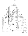
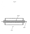
- the portions of transmission lines 3 and 3 'forming part of the first oscillating circuit consist of triaxial or three-conductor portions concentric 5, 5 ", 5" “; 5 ', 5' '', 5" “, at least the first oscillating circuit 4 integrating the conductors 5 and 5 'connected directly to the coil 2 of said triaxial lines 3 and 3 ', and at least one other of said oscillating circuits 12, 12 'integrating additional concentric conductors 5 "and 5"' said triaxial lines 3 and 3 ', a transfer of energy being effected between these 5 ", 5" and 5, 5 'respectively associated concentric conductors, due to the distributed linear capacitance of said triaxial lines 3 and 3 '.
- the connected conductors 5 and 5 ' directly to the coil 2 of the triaxial lines 3 and 3 ' are formed by the intermediate conductors of the latter at least one of the circuits additional oscillating 12, 12 'is connected to and integrates the conductors central 5 "and 5" 'not connected to the coil 2, the linear capacitance distributed between these central and intermediate conductors providing a connection through energy transfer enabling said additional oscillating circuit considered 12, 12 'to loop on the coil 2 via the intermediate conductors 5 and 5 '( Figure 4).
- the intermediate conductors 5 and 5 'each have a cut or physical discontinuity 34 at a non-interfering cold point 27, 27 ' respective portions and additional lines 13, 13 ', 14, 14' of one at least additional oscillating circuits 12, 12 'are connected to the level of said cold spots at the portions of the intermediate conductors 5, 5 ' connected to the coil 2, the parts of said conductors 5 and 5 'facing the level of said cut or discontinuity 34 being interconnected by frequency-selective energy transfer circuits 32, for example bandpass filters centered on the resonance frequency of the first circuit oscillating 4 and transmitting the maximum energy for this frequency.
- frequency-selective energy transfer circuits 32 for example bandpass filters centered on the resonance frequency of the first circuit oscillating 4 and transmitting the maximum energy for this frequency.
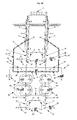
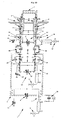
- the connected conductors 5 and 5 ' directly to the coil 2 of the triaxial lines 3 and 3 ' are formed by the central conductors thereof and at least one of the oscillating circuits additional 12 integrates the intermediate conductors 5 "and 5" 'no connected to the coil 2, the linear capacitance distributed between these conductors central and intermediate providing a connection by energy transfer allowing said additional oscillating circuit considered 12, 12 'to loop on the coil 2 via the central conductors 5 and 5 ' ( Figures 5A, 5B and 5C).
- the conductors 13 "; 14" of additional line portions 13, 13 '; 14, 14 ' of at least one additional oscillating circuit 12 ' are connected to the central conductors 5 and 5 'at non-interfering cold points 27, 27 'of these conductors, that rejecting filters 29 insulate between them the first oscillating circuit 4 and the oscillating circuit (s) additional 12 'whose conductors 13 ", 14" are connected to said central conductors 5 and 5 'and that the latter oscillating circuits 4 and 12' are also, together, isolated from said at least one oscillating circuit additional 12 integrating the intermediate conductors 5 "and 5" 'no connected to the coil 2 by rejecting filters 28.
- each triaxial line portion 3, 3 ' can be constituted for example by a cable coaxial mounted either in a metal tube (forming the outer conductor), in place of the central conductor of a larger coaxial cable diameter.
- an additional oscillating circuit (to symmetrical structure), associated with a resonance frequency corresponding, has substantially no influence on the oscillating circuits already part of the feeding circuit, and in particular does not no dissymmetry in these existing circuits.
- the transmission line portions 3 and 3 ' used by all oscillating circuits 4, 12, 12 '(and at least partly common to these), are not modified and are not the subject of any adjustment operation, even when adding a new oscillating circuit.
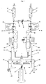
- the subject of the invention is also an NMR probe 33 multi-frequency device, characterized in that it comprises, at least in part, a supply circuit 1 of the sample coil having at least some of the features outlined above (see Figures 8A, 8B, 9, 10A, 10B and 10C).
- the invention also covers an NMR spectrometer, in particular for solid phase spectrometry, characterized in that comprises a supply circuit 1 of the sample coil 2 such that described above and a probe of the type mentioned above.
Landscapes
- Physics & Mathematics (AREA)
- Condensed Matter Physics & Semiconductors (AREA)
- General Physics & Mathematics (AREA)
- Magnetic Resonance Imaging Apparatus (AREA)
- Inductance-Capacitance Distribution Constants And Capacitance-Resistance Oscillators (AREA)
- Investigating Or Analyzing Materials By The Use Of Magnetic Means (AREA)
- Measuring Magnetic Variables (AREA)
- Burglar Alarm Systems (AREA)
- Electronic Switches (AREA)
- Details Of Television Scanning (AREA)
Abstract
Description
Claims (28)
- Circuit d'alimentation d'une bobine, notamment d'une bobine RMN ou bobine d'échantillon, comprenant deux portions de ligne d'alimentation ou de transmission reliées chacune à l'une des deux extrémités de cette bobine, lesdites portions de ligne formant avec ladite bobine un circuit oscillant ou premier circuit oscillant présentant une fréquence de résonance déterminée, caractérisé en ce que les deux portions de ligne (3, 3') comportent chacune au moins deux conducteurs (5, 5' ; 5", 5"'), dont l'un (5, 5') est relié à la bobine (2), et présentent entre elles des structures identiques et des longueurs de conducteurs reliés identiques, cette longueur commune étant sensiblement un multiple de la moitié de la longueur d'onde de résonance dudit circuit oscillant (4), en ce que les conducteurs (5, 5') reliés à la bobine (2) à l'une de leurs extrémités sont reliés entre eux à leur autre extrémité par un circuit ou composant d'accord symétrique réglable (6) complétant ce circuit oscillant (4), et en ce que ledit circuit oscillant (4) à structure symétrique est alimenté par un circuit d'alimentation primaire (7) par l'intermédiaire d'un transfert d'énergie par couplage magnétique, capacitif ou magnéto-capacitif dudit circuit d'alimentation primaire (7) avec l'un au moins des deux conducteurs (5, 5') reliés à la bobine (2) et au circuit ou composant d'accord (6).
- Circuit d'alimentation selon la revendication 1, caractérisé en ce que le circuit d'alimentation primaire (7) est partiellement confondu avec le premier circuit oscillant (4), en intégrant une partie de circuit (7') commune avec ce premier circuit oscillant, et en ce qu'il comprend, d'une part, un générateur radiofréquence (8) ajusté à la fréquence de résonance déterminée du premier circuit oscillant (4) et relié audit premier circuit oscillant (4) au niveau d'une borne du circuit ou composant d'accord symétrique réglable (6) par l'intermédiaire d'une capacité de couplage (8') et, d'autre part, un circuit ou composant d'adaptation (10) relié à l'autre borne du circuit ou composant d'accord symétrique réglable (6), le composant d'adaptation (10) et le composant d'accord symétrique réglable (6) faisant partie des deux circuits (4 et 7), consistant en des capacités et le générateur (8) fonctionnant de manière continue, par intermittence ou de manière pulsée.
- Circuit d'alimentation selon la revendication 1, caractérisé en ce que le circuit d'alimentation primaire (7) consiste en un circuit séparé et comprend, en plus d'un générateur radiofréquence (8) ajusté à la fréquence de résonance déterminée et du ou des éléments (9, 9') participant au couplage avec l'un au moins des deux conducteurs (5, 5') d'une ou des portions de ligne (3, 3') relié à la bobine (2) et au circuit ou composant d'accord (6), également un circuit ou composant d'adaptation (10), destiné à optimiser le couplage et à en limiter certains effets au niveau du circuit d'alimentation primaire (7), le générateur (8) fonctionnant de manière continue, par intermittence ou de manière pulsée.
- Circuit d'alimentation selon l'une quelconque des revendications 1 et 3, caractérisé en ce que le couplage est un couplage essentiellement de nature magnétique et en ce que le circuit ou composant d'adaptation (10) est une capacité réglable destinée à annuler la réactance inductive au niveau du circuit d'alimentation primaire (7).
- Circuit d'alimentation selon l'une quelconque des revendications 1, 3 et 4, caractérisé en ce que le transfert d'énergie par couplage entre le circuit d'alimentation primaire (7) et le circuit oscillant (4) consiste en un couplage double et affecte de manière symétrique et équivalente les conducteurs (5 et 5' ; 5", 5"') reliés à la bobine (2) des deux portions de ligne de transmission (3 et 3').
- Circuit d'alimentation selon l'une quelconque des revendications 4 et 5, pour autant qu'elles dépendent de la revendication 3, caractérisé en ce que le ou chacun des deux couplage(s) réalisant le transfert d'énergie consiste en un couplage principalement magnétique entre, d'une part, un segment (11) d'un conducteur (5, 5') relié à la bobine (2) d'une des portions de ligne (3, 3') du circuit oscillant (4) et, d'autre part, un segment (9, 9') de la ligne reliant le générateur (8) au composant d'adaptation (10) dans le circuit d'alimentation primaire (7), ces deux segments (11 et 9, 9') de longueurs déterminées étant disposés parallèlement et à proximité l'un de l'autre et formant des lignes de Lecher.
- Circuit d'alimentation selon l'une quelconque des revendications 4 et 5, pour autant qu'elles dépendent de la revendication 3, caractérisé en ce que le couplage réalisant le transfert d'énergie consiste en un couplage magnéto-capacitif, symétrique ou asymétrique, entre, d'une part, un solénoïde (9) monté en série dans le circuit d'alimentation primaire (7) et, d'autre part, un ensemble (11') capacité/inductance(s) monté en série dans le circuit oscillant (4), ladite capacité pouvant correspondre au composant d'accord (6) et les inductances comprendre deux inductances équivalentes (15, 15') montées en série de part et d'autre de ladite capacité (6), en faisant éventuellement partie chacune d'un circuit LC.
- Circuit d'alimentation selon l'une quelconque des revendications 1 à 7, caractérisé en ce qu'il comprend au moins un circuit oscillant supplémentaire (12, 12') présentant une fréquence de résonance différente de celle du premier circuit oscillant (4) et formé, le cas échéant chacun, par la bobine (2), des parties mutuellement équivalentes d'un conducteur (5, 5', 5", 5"') des deux portions de ligne (3, 3') du premier circuit oscillant (4) et, éventuellement, deux portions de ligne de transmission additionnelles (13, 13' ; 14, 14') reliées chacune par l'une des extrémités de leur au moins un conducteur (13", 14") respectif à l'un des conducteurs (5, 5" ; 5', 5"') de l'une des deux portions de ligne (3, 3') précitées et présentant entre elles des structures et des longueurs identiques, en ce que la somme de la longueur de chacune desdites deux portions de lignes de transmission additionnelles (13, 13' ; 14, 14') et de la longueur de la partie de conducteur (5, 5' ; 5", 5"') respectivement associée de l'une des deux portions de ligne (3, 3') est un multiple de la demi-longueur d'onde de résonance du circuit oscillant supplémentaire considéré (12, 12'), en ce que les lignes de transmission additionnelles (13, 13' ; 14, 14') sont reliées à leur autre extrémité à un circuit ou composant d'accord (6', 6") et en ce que ledit au moins un ou chaque circuit oscillant supplémentaire (12, 12') est alimenté par un circuit d'alimentation primaire (16, 16') propre correspondant, ce par l'intermédiaire d'un transfert d'énergie par couplage magnétique, capacitif ou magnéto-capacitif de ce circuit d'alimentation primaire (16, 16') respectif correspondant avec au moins un des conducteurs (13" ; 14") reliés aux ou faisant partie des portions de ligne (3, 3') du premier circuit oscillant (4), d'au moins une des deux portions de ligne de transmission additionnelles (13, 13' ; 14, 14').
- Circuit d'alimentation selon la revendication 8, caractérisé en ce que le circuit d'alimentation primaire (16, 16') propre à chaque circuit oscillant supplémentaire (12, 12') est partiellement confondu avec le circuit oscillant supplémentaire associé en intégrant une partie de circuit commune avec ce circuit oscillant supplémentaire, et en ce qu'il comprend, d'une part, un générateur radiofréquence ajusté à la fréquence de résonance déterminée dudit circuit oscillant supplémentaire concerné et relié à ce dernier au niveau d'une borne du circuit ou composant d'accord symétrique réglable de ce circuit oscillant supplémentaire par l'intermédiaire d'une capacité de couplage et, d'autre part, un circuit ou composant d'adaptation relié à l'autre borne du circuit ou composant d'accord symétrique réglable précité, le composant d'adaptation et le composant d'accord symétrique réglable précités faisant partie des deux circuits, consistant en des capacités.
- Circuit d'alimentation selon la revendication 8, caractérisé en ce que le circuit d'alimentation primaire (16 ; 16') propre à chaque circuit oscillant supplémentaire (12 ; 12') comprend, en plus d'un générateur radiofréquence (17 ; 17') ajusté à la fréquence de résonance déterminée et du ou des éléments (18, 18' ; 19, 19') participant au couplage avec l'un au moins des conducteurs (13" ; 14") des portions de ligne additionnelles (13', 13" ; 14', 14"), un circuit ou composant d'adaptation (20 ; 20'), destiné à optimiser le couplage et à en limiter certains effets au niveau dudit circuit d'alimentation primaire propre (16 ; 16'), le générateur (17, 17') fonctionnant de manière continue, par intermittence ou de manière pulsée.
- Circuit d'alimentation selon l'une quelconque des revendications 8 et 10, caractérisé en ce que le couplage à transfert d'énergie entre le ou chaque circuit oscillant supplémentaire (12 ; 12') et son circuit d'alimentation primaire propre ou respectivement associé (16 ; 16') consiste en un couplage essentiellement magnétique et en ce que le circuit ou composant d'adaptation (20 ; 20') est une capacité réglable destinée à annuler la réactance inductive au niveau du circuit d'alimentation primaire propre considéré (16 ; 16').
- Circuit d'alimentation selon l'une quelconque des revendications 8, 10 et 11, caractérisé en ce que le transfert d'énergie par couplage entre le circuit d'alimentation primaire propre (16 ; 16') associé à un circuit oscillant supplémentaire (12 ; 12') et ce dernier consiste en un couplage double, avec éventuellement deux zones de couplage sensiblement identiques et affectant de manière symétrique et équivalente les conducteurs (13" ; 14") des portions de lignes de transmission additionnelles (13, 13' ; 14, 14'), reliés aux portions de ligne de transmission (3, 3') du premier circuit oscillant (4).
- Circuit d'alimentation selon l'une quelconque des revendications 11 et 12, pour autant qu'elles se rattachent à la revendication 10, caractérisé en ce que le ou chacun des deux couplage(s) réalisant le transfert d'énergie entre un circuit d'alimentation primaire (16 ;16') propre à un circuit oscillant supplémentaire (12 ; 12') et ce dernier consiste en un couplage magnétique entre, d'une part, un segment (21 ; 21') d'un conducteur (13" ; 14") d'une portion de ligne additionnelle (13, 13' ; 14, 14'), relié à l'une des portions de ligne (3, 3') du premier circuit oscillant (4), et, d'autre part, un segment (18, 18' ; 19, 19') de la ligne reliant le générateur (17 ; 17') au composant d'adaptation (20 ; 20') dans le circuit d'alimentation primaire (16 ; 16') propre associé au circuit oscillant supplémentaire (12 ; 12') considéré, ces deux segments (21 ; 21' et 18, 18' ; 19, 19') de longueurs déterminées étant disposés parallèlement et à proximité l'un de l'autre et formant des lignes de Lecher.
- Circuit d'alimentation selon l'une quelconque des revendications 11 et 12, pour autant qu'elles se rattachent à la revendication 10, caractérisé en ce que le couplage réalisant le transfert d'énergie entre le circuit d'alimentation primaire (16 ; 16') propre à un circuit oscillant supplémentaire (12 ; 12') et ce dernier consiste en un couplage magnéto-capacitif, symétrique ou asymétrique, entre, d'une part, un solénoïde (18 ; 19) monté en série dans ledit circuit d'alimentation primaire propre (16 , 16') et, d'autre part, un ensemble (24 ; 24') capacité/inductance(s) monté en série dans le circuit oscillant supplémentaire considéré (12 ; 12'), ladite capacité pouvant correspondre au composant d'accord (6' ; 6") et les inductances pouvant comprendre deux inductances (25, 25' ; 26, 26') montées en série de part et d'autre de ladite capacité (6' ; 6"), en faisant éventuellement partie chacune d'un circuit LC.
- Circuit d'alimentation selon l'une quelconque des revendications 1 à 14, caractérisé en ce que les deux portions de ligne additionnelles (13 et 13' ; 14 et 14') faisant partie dudit au moins un ou de chaque circuit oscillant supplémentaire (12 ; 12') sont reliées respectivement aux portions de ligne (3 et 3') faisant partie du premier circuit oscillant (4) au niveau de points froids non interférants (27, 27') des conducteurs (5, 5') de ces dernières portions de ligne (3 et 3').
- Circuit d'alimentation selon l'une quelconque des revendications 8 à 14, caractérisé en ce que les deux portions de ligne additionnelles (13 et 13' ; 14 et 14') faisant partie dudit au moins un circuit oscillant supplémentaire (12 ; 12') sont reliées respectivement aux portions de ligne (3 et 3') faisant partie du premier circuit oscillant (4) au niveau des bornes du circuit ou composant d'accord (6) dudit premier circuit oscillant (4).
- Circuit d'alimentation selon l'une quelconque des revendications 8 à 16, caractérisé en ce que le premier circuit oscillant (4) et/ou le ou au moins l'un des circuit(s) oscillant(s) supplémentaire(s) (12 ; 12') intègre(nt) un ou des filtres d'isolation (28, 29) réjecteurs de bande ajusté(s), le cas échéant chacun, sur la fréquence de résonance de l'autre ou de l'un des autres circuit(s) oscillant(s) (4, 12 ou 12').
- Circuit d'isolation selon la revendication 17, caractérisé en ce que les filtres d'isolation (28, 29) se présentent sous la forme de paire(s) de filtres (28 ou 29), chaque filtre d'une paire donnée de filtres (28, 29) étant relié en série à ou monté en série avec l'un des conducteurs (5, 5') reliés à la bobine (2) du premier circuit oscillant (4) ou à l'un des conducteurs (13" ; 14") des portions de lignes additionnelles (13, 13' ; 14, 14') du circuit oscillant supplémentaire (12 ou 12') considéré, relié à une ligne de transmission (3, 3') du premier circuit oscillant (4).
- Circuit d'alimentation selon la revendication 17 ou 18, caractérisé en ce que en présence d'un premier circuit oscillant (4) et de deux circuits oscillants supplémentaires (12 et 12'), au moins l'un desdits circuits oscillants (4, 12, 12') intègre deux paires de filtres d'isolation (28 et 29), chaque paire de filtres (28, 29) étant ajustée sur la fréquence de résonance de l'un (4, 12 ou 12') des deux autres circuits oscillants (4, 12, 12'), l'une des paires de filtres (29) au moins étant réglable en fréquence, préférentiellement de manière continue.
- Circuit d'alimentation selon l'une quelconque des revendications 17 et 18, caractérisé en ce que les filtres d'isolation (28, 29) consistent en des paires de circuits LC, la ou les paire(s) de filtres (29) éventuellement réglable(s) en fréquence intégrant des capacités (30) variables de manière continue avec un asservissement mécanique mutuel (31) de leur réglage.
- Circuit d'alimentation selon l'une quelconque des revendications 8 à 20, caractérisé en ce que les lignes de transmission (3 et 3') faisant partie du premier circuit oscillant (4) consistent en des lignes coaxiales, ainsi que préférentiellement les lignes de transmission additionnelles (13, 13' ; 14, 14').
- Circuit d'alimentation selon l'une quelconque des revendications 8 à 20, caractérisé en ce que les portions de lignes de transmission (3 et 3') faisant partie du premier circuit oscillant consistent en des portions de lignes triaxiales ou à trois conducteurs concentriques (5, 5", 5"" ; 5', 5''', 5""), au moins le premier circuit oscillant (4) intégrant les conducteurs (5 et 5') reliés directement à la bobine (2) desdites lignes triaxiales (3 et 3'), et au moins un autre desdits circuits oscillants (12, 12') intégrant des conducteurs concentriques supplémentaires (5" et 5"') desdites lignes triaxiales (3 et 3'), un transfert d'énergie s'effectuant entre ces conducteurs (5", 5"' et 5, 5') concentriques respectivement associés, du fait de la capacité linéique répartie desdites lignes triaxiales (3 et 3').
- Circuit d'alimentation selon la revendication 22, caractérisé en ce que les conducteurs (5 et 5') reliés directement à la bobine (2) des lignes triaxiales (3 et 3') sont constitués par les conducteurs intermédiaires de ces dernières et en ce qu'au moins un des circuits oscillants supplémentaires (12, 12') est relié aux et intègre les conducteurs centraux (5" et 5"') non reliés à la bobine (2), la capacité linéique répartie entre ces conducteurs centraux et intermédiaires fournissant une connexion par transfert d'énergie permettant audit circuit oscillant supplémentaire considéré (12, 12') de se boucler sur la bobine (2) par l'intermédiaire des conducteurs intermédiaires (5 et 5').
- Circuit d'alimentation selon la revendication 23, caractérisé en ce que les conducteurs intermédiaires (5 et 5') présentent chacun une coupure ou discontinuité physique (34) au niveau d'un point froid non interférent (27, 27') respectif et en ce que les portions de lignes additionnelles (13, 13' ;14, 14') de l'un au moins des circuits oscillants supplémentaires (12, 12') sont reliées au niveau desdits points froids aux parties des conducteurs intermédiaires (5, 5') reliées à la bobine (2), les parties desdits conducteurs (5 et 5') en regard au niveau de ladite coupure ou discontinuité (34) étant reliées entre elles par des circuits de transfert d'énergie (32) sélectifs en fréquence, par exemple des filtres passe-bandes centrés sur la fréquence de résonance du premier circuit oscillant (4) et transmettant le maximum d'énergie pour cette fréquence.
- Circuit d'alimentation selon la revendication 22, caractérisé en ce que les conducteurs (5 et 5') reliés directement à la bobine (2) des lignes triaxiales (3 et 3') sont constitués par les conducteurs centraux de ces dernières et en ce qu'au moins un des circuits oscillants supplémentaires (12) intègre les conducteurs intermédiaires (5" et 5"') non reliés à la bobine (2), la capacité linéique répartie entre ces conducteurs centraux et intermédiaires fournissant une connexion par transfert d'énergie permettant audit circuit oscillant supplémentaire considéré (12, 12') de se boucler sur la bobine (2) par l'intermédiaire des conducteurs centraux (5 et 5').
- Circuit d'alimentation selon la revendication 25, caractérisé en ce que les conducteurs (13" ; 14") des portions de lignes additionnelles (13, 13' ; 14, 14') d'au moins un autre circuit oscillant supplémentaire (12') sont reliés aux conducteurs centraux (5 et 5') au niveau de points froids non interférents (27, 27') de ces conducteurs, en ce que des filtres réjecteurs (29) isolent entre eux le premier circuit oscillant (4) et le ou les circuit(s) oscillant(s) supplémentaire(s) (12') dont les conducteurs (13", 14") sont reliés auxdits conducteurs centraux (5 et 5') et en ce que ces derniers circuits oscillants (4 et 12') sont également, ensemble, isolés dudit au moins un circuit oscillant supplémentaire (12) intégrant les conducteurs intermédiaires (5" et 5"') non reliés à la bobine (2), par des filtres réjecteurs (28).
- Sonde RMN multifréquence, caractérisée en ce qu'elle est pourvue d'un circuit d'alimentation (1) de la bobine d'échantillon (2) selon l'une quelconque des revendications 1 à 26.
- Spectromètre RMN, en particulier pour spectrométrie en phase solide, caractérisé en ce qu'il comprend un circuit d'alimentation (1) de la bobine d'échantillon (2) selon l'une quelconque des revendications 1 à 26.
Applications Claiming Priority (2)
| Application Number | Priority Date | Filing Date | Title |
|---|---|---|---|
| FR0406663A FR2871892B1 (fr) | 2004-06-18 | 2004-06-18 | Circuit d'alimentation d'une bobine et sonde et spectrometre rmn comportant un tel circuit |
| FR0406663 | 2004-06-18 |
Publications (2)
| Publication Number | Publication Date |
|---|---|
| EP1607760A1 true EP1607760A1 (fr) | 2005-12-21 |
| EP1607760B1 EP1607760B1 (fr) | 2009-07-22 |
Family
ID=34949305
Family Applications (1)
| Application Number | Title | Priority Date | Filing Date |
|---|---|---|---|
| EP05360019A Expired - Lifetime EP1607760B1 (fr) | 2004-06-18 | 2005-05-27 | Circuit d'alimentation d'une bobine et sonde et spectomètre RMN comportant un tel circuit |
Country Status (7)
| Country | Link |
|---|---|
| US (1) | US7196522B2 (fr) |
| EP (1) | EP1607760B1 (fr) |
| JP (1) | JP4477551B2 (fr) |
| AT (1) | ATE437373T1 (fr) |
| DE (1) | DE602005015514D1 (fr) |
| ES (1) | ES2330234T3 (fr) |
| FR (1) | FR2871892B1 (fr) |
Families Citing this family (6)
| Publication number | Priority date | Publication date | Assignee | Title |
|---|---|---|---|---|
| DE10361347B4 (de) * | 2003-12-16 | 2012-01-19 | Bruker Biospin Gmbh | Probenkopf für Kernresonanzmessungen |
| JP5182742B2 (ja) * | 2007-08-14 | 2013-04-17 | 株式会社 Jeol Resonance | Nmr検出器 |
| JP5112001B2 (ja) * | 2007-10-16 | 2013-01-09 | 株式会社日立製作所 | Nmrプローブ |
| FR2924501B1 (fr) * | 2007-12-04 | 2010-02-05 | Commissariat Energie Atomique | Procede de reglage d'un circuit d'excitation et detection pour resonance magnetique nucleaire et circuit d'excitation et detection adapte a la mise en oeuvre d'un tel procede |
| DE102009047565A1 (de) * | 2009-12-07 | 2011-06-09 | Bruker Biospin Ag | Verfahren zur Regelung von HF-Signalen in einem NMR-System sowie Probenkopf zur Durchführung des Verfahrens |
| US20240364293A1 (en) * | 2023-04-25 | 2024-10-31 | Young In Ace Co., Ltd. | Impedance Matching Circuit Using Insulated Air Core Transformer and Mass Spectrometer Including the Same |
Citations (3)
| Publication number | Priority date | Publication date | Assignee | Title |
|---|---|---|---|---|
| EP0073614A2 (fr) * | 1981-08-24 | 1983-03-09 | Monsanto Company | Capteur à bobine simple à accord double pour un spectromètre à résonance magnétique nucléaire |
| EP0890848A1 (fr) * | 1997-07-10 | 1999-01-13 | Jacob Schaefer | Sonde pour un spectromètre de résonance magnétique nucléaire comprenant une bobine unique réglée sur plusieurs fréquences à l'aide d'un réseau de lignes de transmission |
| EP1249709A1 (fr) | 2001-04-10 | 2002-10-16 | Jeol Ltd. | Circuit à multiples résonances et sonde pour spectromètre RMN |
Family Cites Families (12)
| Publication number | Priority date | Publication date | Assignee | Title |
|---|---|---|---|---|
| US4594566A (en) * | 1984-08-30 | 1986-06-10 | Advanced Nmr Systems, Inc. | High frequency rf coil for NMR device |
| US4812764A (en) * | 1988-03-31 | 1989-03-14 | Varian Associates, Inc. | Calibrated decoupling of tightly coupled concentric surface coils |
| US4833412A (en) * | 1988-04-08 | 1989-05-23 | Varian Associates, Inc. | Double tuned circuit for distributed lumped capacitance observe coils |
| EP0389868B1 (fr) * | 1989-03-29 | 1995-09-13 | Siemens Aktiengesellschaft | Tomographe par spins nucléaires |
| DE4002160A1 (de) * | 1990-01-25 | 1991-08-08 | Bruker Analytische Messtechnik | Probenkopf fuer kernresonanzmessungen und verfahren zur messung von kernresonanzen |
| US5243289A (en) * | 1991-08-09 | 1993-09-07 | The Trustees Of The University Of Pennsylvania | Multiply-tuned probe for magnetic resonance imaging or spectroscopy |
| US5949311A (en) * | 1997-06-06 | 1999-09-07 | Massachusetts Institute Of Technology | Tunable resonators |
| DE19923294C1 (de) * | 1999-05-21 | 2001-02-15 | Bruker Analytik Gmbh | Probenkopf für Kernresonanzmessungen |
| US6980000B2 (en) * | 2003-04-29 | 2005-12-27 | Varian, Inc. | Coils for high frequency MRI |
| DE10361347B4 (de) * | 2003-12-16 | 2012-01-19 | Bruker Biospin Gmbh | Probenkopf für Kernresonanzmessungen |
| US6933725B2 (en) * | 2004-01-16 | 2005-08-23 | Bruker Biospin Corporation | NMR probe circuit for generating close frequency resonances |
| FR2871891B1 (fr) * | 2004-06-18 | 2006-09-01 | Bruker Biospin Sa Sa | Circuit d'alimentation multifrequencielle et sonde et spectrometre rmn comportant un tel circuit |
-
2004
- 2004-06-18 FR FR0406663A patent/FR2871892B1/fr not_active Expired - Fee Related
-
2005
- 2005-05-27 DE DE602005015514T patent/DE602005015514D1/de not_active Expired - Lifetime
- 2005-05-27 EP EP05360019A patent/EP1607760B1/fr not_active Expired - Lifetime
- 2005-05-27 AT AT05360019T patent/ATE437373T1/de not_active IP Right Cessation
- 2005-05-27 ES ES05360019T patent/ES2330234T3/es not_active Expired - Lifetime
- 2005-06-15 JP JP2005174662A patent/JP4477551B2/ja not_active Expired - Fee Related
- 2005-06-20 US US11/155,665 patent/US7196522B2/en not_active Expired - Lifetime
Patent Citations (3)
| Publication number | Priority date | Publication date | Assignee | Title |
|---|---|---|---|---|
| EP0073614A2 (fr) * | 1981-08-24 | 1983-03-09 | Monsanto Company | Capteur à bobine simple à accord double pour un spectromètre à résonance magnétique nucléaire |
| EP0890848A1 (fr) * | 1997-07-10 | 1999-01-13 | Jacob Schaefer | Sonde pour un spectromètre de résonance magnétique nucléaire comprenant une bobine unique réglée sur plusieurs fréquences à l'aide d'un réseau de lignes de transmission |
| EP1249709A1 (fr) | 2001-04-10 | 2002-10-16 | Jeol Ltd. | Circuit à multiples résonances et sonde pour spectromètre RMN |
Non-Patent Citations (1)
| Title |
|---|
| CROSS V.R. ET AL.: "Single coil probe with transmission-line tuning for nuclear magnetic double resonance", REVIEW OF SCIENTIFIC INSTRUMENTS, vol. 47, 1976, pages 1486 - 1488, XP008043907, ISSN: 0034-6748 * |
Also Published As
| Publication number | Publication date |
|---|---|
| DE602005015514D1 (de) | 2009-09-03 |
| FR2871892A1 (fr) | 2005-12-23 |
| FR2871892B1 (fr) | 2006-09-01 |
| EP1607760B1 (fr) | 2009-07-22 |
| ATE437373T1 (de) | 2009-08-15 |
| JP2006003359A (ja) | 2006-01-05 |
| US20050280418A1 (en) | 2005-12-22 |
| ES2330234T3 (es) | 2009-12-07 |
| JP4477551B2 (ja) | 2010-06-09 |
| US7196522B2 (en) | 2007-03-27 |
Similar Documents
| Publication | Publication Date | Title |
|---|---|---|
| EP0047203B1 (fr) | Filtre hyperfréquence à résonateur diélectrique, accordable dans une grande largeur de bande | |
| EP0109867B1 (fr) | Dispositif capteur de champ magnétique alternatif à haute sensibilité, et à large bande, et appareil de mesure l'utilisant | |
| FR2540294A1 (fr) | Filtre hyperfrequence a resonateurs lineaires | |
| FR2992102A1 (fr) | Rail collecteur guide d'onde | |
| FR2583597A1 (fr) | Filtre passe-bande hyperfrequences en mode evanescent | |
| FR2546340A1 (fr) | Filtre hyperfrequence coupe-bande accordable, de type coaxial, a resonateurs dielectriques | |
| FR2597266A1 (fr) | Antenne a large bande | |
| EP1607760B1 (fr) | Circuit d'alimentation d'une bobine et sonde et spectomètre RMN comportant un tel circuit | |
| EP1607761B1 (fr) | Circuit d'alimention multifréquencielle et sonde et spectromètre RMN comportant un tel circuit | |
| EP0445017A1 (fr) | Résonateur coaxial à capacité d'accord répartie | |
| EP0467818B1 (fr) | Elément de transition entre guides d'ondes électromagnétiques, notamment entre un guide d'ondes circulaire et un guide d'ondes coaxial | |
| FR2509536A1 (fr) | Filtre hyperfrequence comportant des couplages entre troncons de ligne et des moyens de reglage | |
| EP0281773A1 (fr) | Filtre hyperfréquence accordable | |
| EP1905120A1 (fr) | Adapteur d'impedance automatique coaxial | |
| FR2509535A1 (fr) | Filtre hyperfrequence comportant des troncons de lignes couples et des moyens de reglage | |
| EP0769213B1 (fr) | Transformateur d'impedance a haute frequence | |
| FR2589650A1 (fr) | Circuit a ligne microbande resonnante | |
| FR2886450A1 (fr) | Composant a capacite distribuee variable | |
| EP0487388B1 (fr) | Inductance, notamment pour ondes courtes | |
| EP0631150B1 (fr) | Sonde à RMN à oscillateur en boucle | |
| CA2182614A1 (fr) | Dispositif de couplage magnetique entre un conducteur principal d'une ligne tem et un guide d'ondes formant resonateur en lambdag/2" | |
| EP0594502A1 (fr) | Filtre agile passe-bande hyperfréquences à cavités bi-modes | |
| FR2496995A1 (fr) | Filtre a elimination de bande accordable mecaniquement et circuit comportant un tel filtre | |
| EP0053986A2 (fr) | Filtre passe-bande accordable sur un nombre prédéterminé de fréquences discrètes réparties dans une large bande de fréquence | |
| FR2646562A1 (fr) | Transition guide-coaxial pour guide d'ondes apte a propager deux ondes en mode te11 |
Legal Events
| Date | Code | Title | Description |
|---|---|---|---|
| PUAI | Public reference made under article 153(3) epc to a published international application that has entered the european phase |
Free format text: ORIGINAL CODE: 0009012 |
|
| AK | Designated contracting states |
Kind code of ref document: A1 Designated state(s): AT BE BG CH CY CZ DE DK EE ES FI FR GB GR HU IE IS IT LI LT LU MC NL PL PT RO SE SI SK TR |
|
| AX | Request for extension of the european patent |
Extension state: AL BA HR LV MK YU |
|
| 17P | Request for examination filed |
Effective date: 20051230 |
|
| AKX | Designation fees paid |
Designated state(s): AT BE BG CH CY CZ DE DK EE ES FI FR GB GR HU IE IS IT LI LT LU MC NL PL PT RO SE SI SK TR |
|
| 17Q | First examination report despatched |
Effective date: 20060814 |
|
| GRAP | Despatch of communication of intention to grant a patent |
Free format text: ORIGINAL CODE: EPIDOSNIGR1 |
|
| GRAS | Grant fee paid |
Free format text: ORIGINAL CODE: EPIDOSNIGR3 |
|
| GRAA | (expected) grant |
Free format text: ORIGINAL CODE: 0009210 |
|
| AK | Designated contracting states |
Kind code of ref document: B1 Designated state(s): AT BE BG CH CY CZ DE DK EE ES FI FR GB GR HU IE IS IT LI LT LU MC NL PL PT RO SE SI SK TR |
|
| REG | Reference to a national code |
Ref country code: GB Ref legal event code: FG4D Free format text: NOT ENGLISH |
|
| REG | Reference to a national code |
Ref country code: CH Ref legal event code: EP |
|
| REG | Reference to a national code |
Ref country code: IE Ref legal event code: FG4D |
|
| REF | Corresponds to: |
Ref document number: 602005015514 Country of ref document: DE Date of ref document: 20090903 Kind code of ref document: P |
|
| REG | Reference to a national code |
Ref country code: CH Ref legal event code: NV Representative=s name: SCHNEIDER FELDMANN AG PATENT- UND MARKENANWAELTE |
|
| REG | Reference to a national code |
Ref country code: ES Ref legal event code: FG2A Ref document number: 2330234 Country of ref document: ES Kind code of ref document: T3 |
|
| PG25 | Lapsed in a contracting state [announced via postgrant information from national office to epo] |
Ref country code: SE Free format text: LAPSE BECAUSE OF FAILURE TO SUBMIT A TRANSLATION OF THE DESCRIPTION OR TO PAY THE FEE WITHIN THE PRESCRIBED TIME-LIMIT Effective date: 20090722 Ref country code: LT Free format text: LAPSE BECAUSE OF FAILURE TO SUBMIT A TRANSLATION OF THE DESCRIPTION OR TO PAY THE FEE WITHIN THE PRESCRIBED TIME-LIMIT Effective date: 20090722 Ref country code: IS Free format text: LAPSE BECAUSE OF FAILURE TO SUBMIT A TRANSLATION OF THE DESCRIPTION OR TO PAY THE FEE WITHIN THE PRESCRIBED TIME-LIMIT Effective date: 20091122 Ref country code: AT Free format text: LAPSE BECAUSE OF FAILURE TO SUBMIT A TRANSLATION OF THE DESCRIPTION OR TO PAY THE FEE WITHIN THE PRESCRIBED TIME-LIMIT Effective date: 20090722 Ref country code: FI Free format text: LAPSE BECAUSE OF FAILURE TO SUBMIT A TRANSLATION OF THE DESCRIPTION OR TO PAY THE FEE WITHIN THE PRESCRIBED TIME-LIMIT Effective date: 20090722 |
|
| PG25 | Lapsed in a contracting state [announced via postgrant information from national office to epo] |
Ref country code: PL Free format text: LAPSE BECAUSE OF FAILURE TO SUBMIT A TRANSLATION OF THE DESCRIPTION OR TO PAY THE FEE WITHIN THE PRESCRIBED TIME-LIMIT Effective date: 20090722 Ref country code: SI Free format text: LAPSE BECAUSE OF FAILURE TO SUBMIT A TRANSLATION OF THE DESCRIPTION OR TO PAY THE FEE WITHIN THE PRESCRIBED TIME-LIMIT Effective date: 20090722 |
|
| REG | Reference to a national code |
Ref country code: IE Ref legal event code: FD4D |
|
| PG25 | Lapsed in a contracting state [announced via postgrant information from national office to epo] |
Ref country code: PT Free format text: LAPSE BECAUSE OF FAILURE TO SUBMIT A TRANSLATION OF THE DESCRIPTION OR TO PAY THE FEE WITHIN THE PRESCRIBED TIME-LIMIT Effective date: 20091122 Ref country code: BG Free format text: LAPSE BECAUSE OF FAILURE TO SUBMIT A TRANSLATION OF THE DESCRIPTION OR TO PAY THE FEE WITHIN THE PRESCRIBED TIME-LIMIT Effective date: 20091022 |
|
| PG25 | Lapsed in a contracting state [announced via postgrant information from national office to epo] |
Ref country code: DK Free format text: LAPSE BECAUSE OF FAILURE TO SUBMIT A TRANSLATION OF THE DESCRIPTION OR TO PAY THE FEE WITHIN THE PRESCRIBED TIME-LIMIT Effective date: 20090722 Ref country code: CZ Free format text: LAPSE BECAUSE OF FAILURE TO SUBMIT A TRANSLATION OF THE DESCRIPTION OR TO PAY THE FEE WITHIN THE PRESCRIBED TIME-LIMIT Effective date: 20090722 Ref country code: IE Free format text: LAPSE BECAUSE OF FAILURE TO SUBMIT A TRANSLATION OF THE DESCRIPTION OR TO PAY THE FEE WITHIN THE PRESCRIBED TIME-LIMIT Effective date: 20090722 Ref country code: EE Free format text: LAPSE BECAUSE OF FAILURE TO SUBMIT A TRANSLATION OF THE DESCRIPTION OR TO PAY THE FEE WITHIN THE PRESCRIBED TIME-LIMIT Effective date: 20090722 Ref country code: RO Free format text: LAPSE BECAUSE OF FAILURE TO SUBMIT A TRANSLATION OF THE DESCRIPTION OR TO PAY THE FEE WITHIN THE PRESCRIBED TIME-LIMIT Effective date: 20090722 |
|
| PLBE | No opposition filed within time limit |
Free format text: ORIGINAL CODE: 0009261 |
|
| STAA | Information on the status of an ep patent application or granted ep patent |
Free format text: STATUS: NO OPPOSITION FILED WITHIN TIME LIMIT |
|
| PG25 | Lapsed in a contracting state [announced via postgrant information from national office to epo] |
Ref country code: SK Free format text: LAPSE BECAUSE OF FAILURE TO SUBMIT A TRANSLATION OF THE DESCRIPTION OR TO PAY THE FEE WITHIN THE PRESCRIBED TIME-LIMIT Effective date: 20090722 |
|
| 26N | No opposition filed |
Effective date: 20100423 |
|
| PG25 | Lapsed in a contracting state [announced via postgrant information from national office to epo] |
Ref country code: GR Free format text: LAPSE BECAUSE OF FAILURE TO SUBMIT A TRANSLATION OF THE DESCRIPTION OR TO PAY THE FEE WITHIN THE PRESCRIBED TIME-LIMIT Effective date: 20091023 |
|
| PG25 | Lapsed in a contracting state [announced via postgrant information from national office to epo] |
Ref country code: MC Free format text: LAPSE BECAUSE OF NON-PAYMENT OF DUE FEES Effective date: 20100531 |
|
| PG25 | Lapsed in a contracting state [announced via postgrant information from national office to epo] |
Ref country code: IT Free format text: LAPSE BECAUSE OF FAILURE TO SUBMIT A TRANSLATION OF THE DESCRIPTION OR TO PAY THE FEE WITHIN THE PRESCRIBED TIME-LIMIT Effective date: 20090722 |
|
| PG25 | Lapsed in a contracting state [announced via postgrant information from national office to epo] |
Ref country code: CY Free format text: LAPSE BECAUSE OF FAILURE TO SUBMIT A TRANSLATION OF THE DESCRIPTION OR TO PAY THE FEE WITHIN THE PRESCRIBED TIME-LIMIT Effective date: 20090722 |
|
| PG25 | Lapsed in a contracting state [announced via postgrant information from national office to epo] |
Ref country code: HU Free format text: LAPSE BECAUSE OF FAILURE TO SUBMIT A TRANSLATION OF THE DESCRIPTION OR TO PAY THE FEE WITHIN THE PRESCRIBED TIME-LIMIT Effective date: 20100123 |
|
| PG25 | Lapsed in a contracting state [announced via postgrant information from national office to epo] |
Ref country code: TR Free format text: LAPSE BECAUSE OF FAILURE TO SUBMIT A TRANSLATION OF THE DESCRIPTION OR TO PAY THE FEE WITHIN THE PRESCRIBED TIME-LIMIT Effective date: 20090722 |
|
| PGFP | Annual fee paid to national office [announced via postgrant information from national office to epo] |
Ref country code: NL Payment date: 20140304 Year of fee payment: 10 |
|
| PGFP | Annual fee paid to national office [announced via postgrant information from national office to epo] |
Ref country code: LU Payment date: 20140502 Year of fee payment: 10 |
|
| PGFP | Annual fee paid to national office [announced via postgrant information from national office to epo] |
Ref country code: BE Payment date: 20140319 Year of fee payment: 10 |
|
| PGFP | Annual fee paid to national office [announced via postgrant information from national office to epo] |
Ref country code: ES Payment date: 20150507 Year of fee payment: 11 |
|
| PG25 | Lapsed in a contracting state [announced via postgrant information from national office to epo] |
Ref country code: LU Free format text: LAPSE BECAUSE OF NON-PAYMENT OF DUE FEES Effective date: 20150527 |
|
| REG | Reference to a national code |
Ref country code: NL Ref legal event code: MM Effective date: 20150601 |
|
| REG | Reference to a national code |
Ref country code: FR Ref legal event code: PLFP Year of fee payment: 12 |
|
| PG25 | Lapsed in a contracting state [announced via postgrant information from national office to epo] |
Ref country code: NL Free format text: LAPSE BECAUSE OF NON-PAYMENT OF DUE FEES Effective date: 20150601 |
|
| REG | Reference to a national code |
Ref country code: FR Ref legal event code: PLFP Year of fee payment: 13 |
|
| PG25 | Lapsed in a contracting state [announced via postgrant information from national office to epo] |
Ref country code: BE Free format text: LAPSE BECAUSE OF NON-PAYMENT OF DUE FEES Effective date: 20150531 |
|
| REG | Reference to a national code |
Ref country code: FR Ref legal event code: PLFP Year of fee payment: 14 |
|
| PG25 | Lapsed in a contracting state [announced via postgrant information from national office to epo] |
Ref country code: ES Free format text: LAPSE BECAUSE OF NON-PAYMENT OF DUE FEES Effective date: 20160528 |
|
| PGFP | Annual fee paid to national office [announced via postgrant information from national office to epo] |
Ref country code: DE Payment date: 20180524 Year of fee payment: 14 Ref country code: CH Payment date: 20180523 Year of fee payment: 14 |
|
| PGFP | Annual fee paid to national office [announced via postgrant information from national office to epo] |
Ref country code: FR Payment date: 20180523 Year of fee payment: 14 |
|
| PGFP | Annual fee paid to national office [announced via postgrant information from national office to epo] |
Ref country code: GB Payment date: 20180523 Year of fee payment: 14 |
|
| REG | Reference to a national code |
Ref country code: ES Ref legal event code: FD2A Effective date: 20181204 |
|
| REG | Reference to a national code |
Ref country code: DE Ref legal event code: R119 Ref document number: 602005015514 Country of ref document: DE |
|
| REG | Reference to a national code |
Ref country code: CH Ref legal event code: PL |
|
| GBPC | Gb: european patent ceased through non-payment of renewal fee |
Effective date: 20190527 |
|
| PG25 | Lapsed in a contracting state [announced via postgrant information from national office to epo] |
Ref country code: CH Free format text: LAPSE BECAUSE OF NON-PAYMENT OF DUE FEES Effective date: 20190531 Ref country code: LI Free format text: LAPSE BECAUSE OF NON-PAYMENT OF DUE FEES Effective date: 20190531 |
|
| PG25 | Lapsed in a contracting state [announced via postgrant information from national office to epo] |
Ref country code: DE Free format text: LAPSE BECAUSE OF NON-PAYMENT OF DUE FEES Effective date: 20191203 Ref country code: GB Free format text: LAPSE BECAUSE OF NON-PAYMENT OF DUE FEES Effective date: 20190527 |
|
| PG25 | Lapsed in a contracting state [announced via postgrant information from national office to epo] |
Ref country code: FR Free format text: LAPSE BECAUSE OF NON-PAYMENT OF DUE FEES Effective date: 20190531 |